EP2102890B1 - Differential-pressure dual ion trap mass analyzer and methods of use thereof - Google Patents
Differential-pressure dual ion trap mass analyzer and methods of use thereof Download PDFInfo
- Publication number
- EP2102890B1 EP2102890B1 EP07873672.5A EP07873672A EP2102890B1 EP 2102890 B1 EP2102890 B1 EP 2102890B1 EP 07873672 A EP07873672 A EP 07873672A EP 2102890 B1 EP2102890 B1 EP 2102890B1
- Authority
- EP
- European Patent Office
- Prior art keywords
- ions
- trap
- ion
- ion trap
- mass
- Prior art date
- Legal status (The legal status is an assumption and is not a legal conclusion. Google has not performed a legal analysis and makes no representation as to the accuracy of the status listed.)
- Active
Links
- 238000005040 ion trap Methods 0.000 title claims description 109
- 230000009977 dual effect Effects 0.000 title claims description 43
- 238000000034 method Methods 0.000 title description 33
- 150000002500 ions Chemical class 0.000 claims description 186
- 238000004458 analytical method Methods 0.000 claims description 29
- 239000002243 precursor Substances 0.000 claims description 25
- 238000013467 fragmentation Methods 0.000 claims description 24
- 238000006062 fragmentation reaction Methods 0.000 claims description 24
- 238000001360 collision-induced dissociation Methods 0.000 claims description 14
- 238000001819 mass spectrum Methods 0.000 claims description 13
- 238000012546 transfer Methods 0.000 claims description 10
- 238000005086 pumping Methods 0.000 claims description 6
- 239000012491 analyte Substances 0.000 claims description 5
- 239000012634 fragment Substances 0.000 claims description 5
- 238000006303 photolysis reaction Methods 0.000 claims description 5
- 239000000126 substance Substances 0.000 claims description 4
- 239000007789 gas Substances 0.000 description 30
- 238000002955 isolation Methods 0.000 description 18
- 239000001307 helium Substances 0.000 description 9
- 229910052734 helium Inorganic materials 0.000 description 9
- SWQJXJOGLNCZEY-UHFFFAOYSA-N helium atom Chemical compound [He] SWQJXJOGLNCZEY-UHFFFAOYSA-N 0.000 description 9
- 238000001816 cooling Methods 0.000 description 8
- 238000010494 dissociation reaction Methods 0.000 description 8
- 230000005593 dissociations Effects 0.000 description 8
- 230000005284 excitation Effects 0.000 description 7
- 230000006870 function Effects 0.000 description 7
- 238000004885 tandem mass spectrometry Methods 0.000 description 6
- 230000000694 effects Effects 0.000 description 5
- 230000008569 process Effects 0.000 description 5
- XKRFYHLGVUSROY-UHFFFAOYSA-N Argon Chemical compound [Ar] XKRFYHLGVUSROY-UHFFFAOYSA-N 0.000 description 4
- IJGRMHOSHXDMSA-UHFFFAOYSA-N Atomic nitrogen Chemical compound N#N IJGRMHOSHXDMSA-UHFFFAOYSA-N 0.000 description 4
- 230000008901 benefit Effects 0.000 description 4
- 238000001211 electron capture detection Methods 0.000 description 4
- 238000001077 electron transfer detection Methods 0.000 description 4
- 230000005405 multipole Effects 0.000 description 4
- 230000002829 reductive effect Effects 0.000 description 4
- 230000002411 adverse Effects 0.000 description 3
- 238000010276 construction Methods 0.000 description 3
- 230000001419 dependent effect Effects 0.000 description 3
- 238000013461 design Methods 0.000 description 3
- 238000002347 injection Methods 0.000 description 3
- 239000007924 injection Substances 0.000 description 3
- 238000004519 manufacturing process Methods 0.000 description 3
- 238000005036 potential barrier Methods 0.000 description 3
- 238000002360 preparation method Methods 0.000 description 3
- 238000009825 accumulation Methods 0.000 description 2
- 230000004913 activation Effects 0.000 description 2
- 229910052786 argon Inorganic materials 0.000 description 2
- 238000000065 atmospheric pressure chemical ionisation Methods 0.000 description 2
- 238000000451 chemical ionisation Methods 0.000 description 2
- 238000013016 damping Methods 0.000 description 2
- 230000001627 detrimental effect Effects 0.000 description 2
- 238000010586 diagram Methods 0.000 description 2
- 239000011261 inert gas Substances 0.000 description 2
- 230000000670 limiting effect Effects 0.000 description 2
- 238000004949 mass spectrometry Methods 0.000 description 2
- 238000005259 measurement Methods 0.000 description 2
- 229910052757 nitrogen Inorganic materials 0.000 description 2
- 238000012545 processing Methods 0.000 description 2
- 230000000717 retained effect Effects 0.000 description 2
- 230000035945 sensitivity Effects 0.000 description 2
- 230000003595 spectral effect Effects 0.000 description 2
- 230000009471 action Effects 0.000 description 1
- 230000006978 adaptation Effects 0.000 description 1
- 238000013459 approach Methods 0.000 description 1
- 230000005540 biological transmission Effects 0.000 description 1
- 230000008859 change Effects 0.000 description 1
- 238000006243 chemical reaction Methods 0.000 description 1
- 238000004891 communication Methods 0.000 description 1
- 150000001875 compounds Chemical class 0.000 description 1
- 239000012141 concentrate Substances 0.000 description 1
- 230000003247 decreasing effect Effects 0.000 description 1
- 238000003795 desorption Methods 0.000 description 1
- 238000011161 development Methods 0.000 description 1
- 239000007788 liquid Substances 0.000 description 1
- 239000000463 material Substances 0.000 description 1
- 239000011159 matrix material Substances 0.000 description 1
- 230000007246 mechanism Effects 0.000 description 1
- 238000012986 modification Methods 0.000 description 1
- 230000004048 modification Effects 0.000 description 1
- 230000003534 oscillatory effect Effects 0.000 description 1
- 238000005192 partition Methods 0.000 description 1
- 230000000750 progressive effect Effects 0.000 description 1
- 230000009467 reduction Effects 0.000 description 1
- 239000013557 residual solvent Substances 0.000 description 1
- 238000010561 standard procedure Methods 0.000 description 1
- 230000000153 supplemental effect Effects 0.000 description 1
- 238000006276 transfer reaction Methods 0.000 description 1
Images


Classifications
-
- H—ELECTRICITY
- H01—ELECTRIC ELEMENTS
- H01J—ELECTRIC DISCHARGE TUBES OR DISCHARGE LAMPS
- H01J49/00—Particle spectrometers or separator tubes
- H01J49/02—Details
- H01J49/04—Arrangements for introducing or extracting samples to be analysed, e.g. vacuum locks; Arrangements for external adjustment of electron- or ion-optical components
- H01J49/0409—Sample holders or containers
- H01J49/0418—Sample holders or containers for laser desorption, e.g. matrix-assisted laser desorption/ionisation [MALDI] plates or surface enhanced laser desorption/ionisation [SELDI] plates
-
- H—ELECTRICITY
- H01—ELECTRIC ELEMENTS
- H01J—ELECTRIC DISCHARGE TUBES OR DISCHARGE LAMPS
- H01J49/00—Particle spectrometers or separator tubes
- H01J49/004—Combinations of spectrometers, tandem spectrometers, e.g. MS/MS, MSn
- H01J49/0045—Combinations of spectrometers, tandem spectrometers, e.g. MS/MS, MSn characterised by the fragmentation or other specific reaction
-
- H—ELECTRICITY
- H01—ELECTRIC ELEMENTS
- H01J—ELECTRIC DISCHARGE TUBES OR DISCHARGE LAMPS
- H01J49/00—Particle spectrometers or separator tubes
- H01J49/02—Details
- H01J49/04—Arrangements for introducing or extracting samples to be analysed, e.g. vacuum locks; Arrangements for external adjustment of electron- or ion-optical components
- H01J49/0404—Capillaries used for transferring samples or ions
-
- H—ELECTRICITY
- H01—ELECTRIC ELEMENTS
- H01J—ELECTRIC DISCHARGE TUBES OR DISCHARGE LAMPS
- H01J49/00—Particle spectrometers or separator tubes
- H01J49/26—Mass spectrometers or separator tubes
- H01J49/34—Dynamic spectrometers
- H01J49/42—Stability-of-path spectrometers, e.g. monopole, quadrupole, multipole, farvitrons
- H01J49/4205—Device types
- H01J49/422—Two-dimensional RF ion traps
- H01J49/4225—Multipole linear ion traps, e.g. quadrupoles, hexapoles
Description
- The present invention relates generally to mass spectrometers, and more specifically to a differential-pressure, two-dimensional dual ion trap mass analyzer for use in a mass spectrometer system.
- The two-dimensional quadrupole ion trap mass analyzer (also referred to as the linear ion trap) is well known in the mass spectrometry art, and has become a valuable and widely-used tool for the analysis of a variety of compounds. Generally described, a two-dimensional ion trap consists of a set of four elongated electrodes to which a radio-frequency (RF) trapping voltage is applied in a prescribed phase relationship to radially confine ions to the trap interior. Axial confinement of the ions may be effected by application of a suitable direct current (DC) offset to end sections of the rod electrodes and/or electrodes located longitudinally outward of the rod electrodes. The mass spectrum of the trapped ions may be acquired by mass-sequentially ejecting the ions from the trap interior to an associated detector, either in a radial direction orthogonal to the central longitudinal axis of the ion trap, as described in
U.S. Patent No. 5,420,425 to Bier et al. , or in an axial direction parallel to the central longitudinal axis, as described inU.S. Patent No. 6,177,668 to Hager . The enlarged ion volume, greater trapping capacity, and higher trapping efficiency of the two-dimensional ion trap offers significant performance advantages (relative to the conventional three-dimensional ion trap), including enhanced sensitivity and the ability to perform an increased number of multiple stages of ion selection and fragmentation. - Successful operation of an ion trap mass analyzer requires the addition of a buffer gas (typically helium) to the trap interior. The buffer gas (also variously referred to in the art as damping or collision gas) serves two primary purposes. First, the buffer gas reduces the ions' kinetic energy via collisions. This reduction of kinetic energy is essential, not only for trapping ions injected into the trap, but also for kinetically cooling (damping) and spatially (both axially and radially) concentrating the ion cloud before mass analysis, resulting in useful mass spectral resolution and sensitivity. Second, the presence of the buffer gas enables efficient fragmentation of ions via collision activated dissociation (CAD) for tandem mass spectrometry (MS/MS or MSn) analysis.
- It is known, however, that collisions of ions with buffer gas during the ion isolation and mass-sequential ejection processes may be detrimental to mass spectral performance, both by reducing resolution and by contributing to chemical mass shifts that limit mass accuracy. Instrument designers have attempted to reduce these detrimental effects by selecting a buffer gas pressure (typically between 0.13-0.67Pa (1-5 milliTorr)) that provides adequate trapping/cooling and fragmentation action while minimizing the adverse influence on resolution and mass accuracy. While this "compromise pressure" approach has resulted in generally satisfactory instrument performance, there has been recent interest in modes of operation that favor lower pressures. It is known that higher resolution may be achieved by resonantly ejecting ions at values of the Mathieu parameter q which are somewhat lower than the stability limit value of .908. This gain in resolution may also be traded for more rapid scan rates, i.e., mass spectra having resolution equivalent to that obtained using standard techniques may be acquired more rapidly, thereby increasing sample throughput and/or increasing the numbers of MSn cycles that can be completed. Furthermore, ejection at reduced values of q offers other advantages, including expanded mass range scanning and the possibility of employing higher order resonances to increase ejection rates and/or provide higher mass-to-charge ratio (m/z) resolution. It is noted that the problem of chemically dependent mass shifts, which may increase significantly with lowered q ejection values in certain ion traps and under certain conditions, may present a potential obstacle to the use of reduced-q resonant ejection. Chemically dependent mass shift can be lessened by reducing the buffer gas pressure, but doing so has a substantial adverse effect on the ability to trap and cool ions, and to efficiently fragment ions via the CAD mechanism.
-
U.S. Patent No. 6,960,762 to Kawato et al. , while not specifically addressing reduced-q resonant ejection, describes an adaptation to a conventional three-dimensional ion trap that is designed to avoid the disadvantages arising from the presence of a buffer gas. In the Kawato et al. apparatus, the buffer gas is controllably added (via a pulsed valve) to the ion trap interior to raise the pressure to a value optimized for ion capture. After ions have been injected into the trap, the flow of the inert gas is reduced or terminated and the ion trap interior pressure is consequently lowered to a value optimized for the mass-sequential scan.
By switching between the two pressures, the Kawato et al. apparatus purportedly achieves both excellent capture efficiency and scan resolution. However, the time needed to repeatedly change and stabilize the ion trap pressure may significantly lengthen the overall mass analysis cycle time and reduce sample throughput, particularly where high-capacity ion traps are employed. - At least one prior art reference discloses a dual-trap mass spectrometer architecture in which pressures in the traps are separately optimized for different functions. Zerega et al. ("A Dual Quadrupole Ion Trap Mass Spectrometer", Int. J. Mass Spectrometry 190/191 (1999) 59-68) describes a dual ion trap mass spectrometer consisting of a first three-dimensional quadrupole ion trap (referred to as the "preparation cell") operated at a pressure of approximately 13.33mPa (10-4 Torr), which is coupled to a second three-dimensional quadrupole ion trap (referred to as the "mass analysis cell") operated at a pressure of about 13.33µPa (10-7 Torr). In this mass spectrometer, ions are internally generated within the preparation cell and cooled by collisions with inert gas atoms to reduce the volume occupied by the ion cloud. The ions are then ejected from the preparation cell (by turning off the confinement voltage and applying suitable DC voltages to the end caps) through a small aperture in one of the end caps and travel to the mass analysis cell, where they are admitted into the cell's interior volume through an inlet aperture. The mass-to-charge ratios of the ions trapped in the mass analysis cell are determined by a complex technique based on measurement of the secular frequencies of the trapped ions via trajectory analysis, in which ions are confined within the trap for a prescribed period and then ejected (through an exit aperture) to a detector for generation of an ion signal representative of the ions' time-of-flight between the trap interior and the detector. This technique requires analysis of the ion signal as a function of confinement time, so several mass analysis cycles must be performed to obtain a complete mass spectrum. The complexity of the mass analysis technique disclosed in the Zerega et al. paper, as well as the need to execute several mass analysis cycles to generate a mass spectrum, disfavor commercial use of this apparatus.
-
US-A-2002/0,121,594 describes a mass spectrometer having first and second ion traps separated by an analytical multipole. The mass spectrometer operates in a first, transmission only mode, in which ions pass through the first and second ion traps and through the analytical multipole without analysis or fragmentation. In a second MS/MS mode, ions are selected by the analytical multipole and may be fragmented in the second ion trap. However no analysis of ions takes place in either the first or the second ion trap. -
US-A-2004/079874 describes a mass spectrometer in which ions are ejected from a quadrupole ion trap into an ion trap. The ions are cooled in the ion trap and then pulsed out towards a Time of Flight mass analyser. - According to a first aspect of the present invention, there is provided a dual trap mass analyzer as set out in claim 1.
- Roughly described, a dual-trap mass analyzer according to an embodiment of the present invention includes adjacently disposed first and second two-dimensional quadrupole ion traps operating at different pressures. The first ion trap has an interior volume maintained at a relatively high pressure, for example in the range of 66.65mPa-1.33Pa (5.0x10⁻⁴ to 1.0x10⁻² Torr) of helium, to promote efficient ion trapping, kinetic/spatial cooling, and fragmentation via a CAD process. The cooled (and optionally fragmented) ions are transferred through at least one ion optic element to the interior of the second ion trap, which is maintained at a significantly lower buffer gas pressure (for example, in the range of 1.33Pa-26.66mPa (1.0x10⁻⁵ to 2.0x10⁻⁴ Torr) of helium) relative to the first ion trap pressure. The lower pressure in the second ion trap facilitates the acquisition of high-resolution mass spectra and/or use of higher scan rates while maintaining comparable m/z resolutions, and may also enable the utilization of reduced-q resonant ejection without incurring unacceptable levels of chemically dependant mass shift. In addition, the lower pressure region also allows the possibility of higher resolution ion isolation.
- In a particular implementation of the dual-trap mass analyzer, the first and second ion traps reside in a common vacuum chamber, with the pressure differential between the traps being maintained by a pumping restriction, which may take the form of the aperture of a inter-trap plate lens separating the two traps. A buffer gas, such as helium, may be added to the interior of the first ion trap via a conduit to provide the desired buffer gas pressure. Both the first and second ion traps may have a conventional sectioned hyperbolic rod structure, and the central sections of a rod electrode pair of the second ion trap may be adapted with slots to permit the ejection of ions therethrough to detectors for acquisition of a mass spectrum. A single shared radio-frequency (RF) controller may be employed to apply the RF voltages to electrodes of both ion traps. Axial confinement of ions within the ion traps and transfer of ions between the traps may be achieved by application of the appropriate DC voltages to the rod electrode sections and/or to the inter-trap lens and lenses positioned axially outwardly of the front end of the first ion trap and the back end of the second ion trap.
- The dual-trap mass analyzer of the foregoing description may be operated in a number of different modes. In one mode, ions are trapped and cooled in the first ion trap, and then transferred to the second ion trap for mass analysis (the term "mass analysis" is used herein to denote measurement of the mass-to-charge ratios of the trapped ions). In another mode, ions are trapped and cooled in the first trap, and precursor ions are selected (isolated) for fragmentation by ejecting from the first trap all ions outside of a mass-to-charge range of interest. In accordance with the CAD technique, the precursor ions are then kinetically excited and undergo energetic collisions with the buffer gas to produce product ions. The product ions are then transferred to the second ion trap for mass analysis. Yet another mode of operation makes use of the potential for high-resolution isolation in the second ion trap. In this mode, ions are trapped and cooled in the first ion trap and then transferred into the second ion trap. Precursor ions are then isolated in the second ion trap by ejecting all ions outside of a mass-to-charge range of interest. Due to the low pressure within the second ion trap, isolation may be effected at higher resolution and greater efficiency (less loss of precursor ions) than is attainable at higher pressures, so that precursor ion species may be selected with greater specificity. The precursor ions are then transferred back into the first ion trap and are thereafter fragmented by the aforementioned CAD technique. The resulting product ions are then transferred into the second ion trap for mass analysis. In a variant of this mode of operation, the precursor ions are accelerated to high velocities during transfer from the second ion trap to the first ion trap (by application of appropriate DC voltages to the rod electrodes and/or inter-trap lens) to produce a fragmentation pattern that approximates that occurring in the collision cell of conventional triple-stage quadrupole mass filter instruments. Other known dissociation or reaction techniques, including without limitation photodissociation, electron transfer dissociation (ETD), electron capture dissociation (ECD), and proton transfer reactions (PTR) may be used in place of or in addition to the CAD technique to yield product ions. The product ions may then be transferred back into the second ion trap for mass analysis.
- The foregoing and other embodiments of the present invention avoid or reduce the limitations of prior art ion trap mass analyzers by providing a mass analyzer with regions
of relatively high and low pressures, and by performing those functions favoring higher pressures (cooling and fragmentation) in the high-pressure region and others favoring low pressures (isolation and mass-sequential scans) in the low-pressure region. - In the accompanying drawings:
-
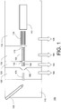
FIG. 1 is a symbolic diagram of a mass spectrometer that includes a differential-pressure dual ion trap mass analyzer, in accordance with an embodiment of the invention; -
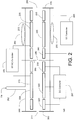
FIG. 2 is a symbolic diagram depicting components of the differential-pressure dual ion trap mass analyzer. -
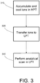
FIG. 3 is a flowchart depicting the steps of a first method for operating the differential-pressure dual ion trap mass analyzer ofFIG. 2 ; -
FIG. 4 is a flowchart depicting the steps of a second method for operating the differential-pressure dual ion trap mass analyzer ofFIG. 2 , whereby ions are isolated and fragmented in the first ion trap; and -
FIG. 5 is a flowchart depicting the steps of a third method for operating the differential-pressure dual ion trap mass analyzer ofFIG. 2 , whereby ions are isolated in the second ion trap and fragmented in the first ion trap. -
FIG. 1 depicts the components of amass spectrometer 100 in which a differential-pressure dual ion trap mass analyzer may be implemented, in accordance with an embodiment of the present invention. It will be understood that certain features and configurations ofmass spectrometer 100 are presented by way of illustrative examples, and should not be construed as limiting the differential-pressure dual ion trap mass analyzer to implementation in a specific environment. An ion source, which may take the form of anelectrospray ion source 105, generates ions from an analyte material, for example the eluate from a liquid chromatograph (not depicted). The ions are transported fromion source chamber 110, which for an electrospray source will typically be held at or near atmospheric pressure, through severalintermediate chambers vacuum chamber 135 in which differential-pressure dual iontrap mass analyzer 140 resides. Efficient transport of ions fromion source 105 tomass analyzer 140 is facilitated by a number of ion optic components, including quadrupole RF ion guides 145 and 150, octopoleRF ion guide 155,skimmer 160, andelectrostatic lenses ion source chamber 110 and firstintermediate chamber 120 through anion transfer tube 175 that is heated to evaporate residual solvent and break up solvent-analyte clusters.Intermediate chambers vacuum chamber 135 are evacuated by a suitable arrangement of pumps to maintain the pressures therein at the desired values. In one example,intermediate chamber 120 communicates with aport 180 of a mechanical pump, andintermediate chambers vacuum chamber 130 communicate withcorresponding ports - The operation of the various components of
mass spectrometer 100 is directed by a control and data system (not depicted), which will typically consist of a combination of general-purpose and specialized processors, application-specific circuitry, and software and firmware instructions. The control and data system also provides data acquisition and post-acquisition data processing services. - While
mass spectrometer 100 is depicted as being configured for an electrospray ion source, it should be noted that the dual iontrap mass analyzer 140 may be employed in connection with any number of pulsed or continuous ion sources (or combinations thereof), including without limitation a matrix assisted laser desorption/ionization (MALDI) source, an atmospheric pressure chemical ionization (APCI) source, an atmospheric pressure photo-ionization (APPI) source, an electron ionization (EI) source, or a chemical ionization (CI) ion source. -
FIG. 2 is a schematic depiction of the major components of a dual iontrap mass analyzer 140, according to an embodiment of the present invention. Dual iontrap mass analyzer 140 includes first and second quadrupole traps 205 and 210 positioned adjacent to one another. For reasons that will become evident in view of the discussion set forth below, firstquadrupole ion trap 205 will be referred to as the high-pressure trap (HPT), and secondquadrupole ion trap 210 will be referred to as the low-pressure trap (LPT). It is noted that the term "adjacent", as used herein to describe the relative positioning ofHPT 205 andLPT 210, is intended to denote thatHPT 205 andLPT 210 are positioned in close proximity, but does not exclude the placement of one or more ion optic elements between the two traps- in fact, the preferred embodiment requires such an ion optic element. - The geometry and positioning of rod electrodes in two-dimensional quadrupole ion traps has been discussed extensively in the literature (see, e.g., the aforementioned
U.S. Patent No. 5,420,425 , as well as Schwartz et al., "A Two-Dimensional Quadrupole Ion Trap Mass Spectrometer", J. Am. Soc. Mass Spectrom. 13:659 (2002)), and hence a detailed description of these aspects is not required and has been omitted. Generally described, a two-dimensional quadrupole ion trap may be constructed from four rod electrodes disposed about the trap interior. The rod electrodes are arranged into two pairs, each pair being opposed across the central longitudinal axis of the trap. In order to closely approximate a pure quadrupole field when the RF voltages are applied, each rod is formed with a truncated hyperbolic surface facing the trap interior. In other implementations, round (circular) or even planar (flat) electrodes can be substituted for the hyperbolic electrodes in order to reduce manufacturing complexity and cost, though such devices generally provide more limited performance. In a preferred implementation, each rod electrode is divided into three electrically isolated sections, consisting of front and back end sections flanking a central section. Sectioning of the rod electrodes allows the application of different DC potentials to each of the sections, such that ions may be primarily contained within a volume extending over a portion of the length of the trap. For example, positive ions may be concentrated within a central volume of the trap interior (which is roughly longitudinally co-extensive with the central sections of the rod electrodes) by raising the DC potential applied to the end sections relative to the central sections. - For the purpose of clarity, only a single electrode pair is depicted in
FIG. 2 forHPT 205 andLPT 210.HPT 205 includesrod electrodes 215 each divided intofront end section 220,central section 225, andback end section 230. Similarly,LPT 210 includesrod electrodes 235 each divided intofront end section 240,central section 245, andback end section 250.Central sections 245 ofrod electrodes 235 may be adapted with slots, in a manner known in the art, to permit radial ejection of ions through the slots todetectors 255 during an analytical scan. It is known that the presence of the slots in the rod electrodes introduces certain higher order field components in the trapping field, which may have undesirable effects on instrument performance. These effects may be avoided or minimized by stretching (increasing the inter-electrode spacing of) one of the electrode pairs, by modifying the surface geometry of the electrodes, or by unbalancing the RF voltages applied to the electrodes. Typically, only two of the rod electrodes will be adapted with slots (i.e., both electrodes of an opposed pair of electrodes), but certain implementations ofLPT 210 may utilize a design in which slots are formed in all four rod electrodes. Thecentral sections 225 ofelectrodes 215 do not need to be adapted with slots, sinceHPT 205 is not used for analytical scans, and soHPT 205 is capable of generating a substantially pure quadrupolar trapping field; however, it may be desirable to utilize electrode geometries and spacings inHPT 205 that result in a departure from a substantially pure quadrupolar field in order, for example, to introduce higher order fields that improve or preserve resonant activation efficiency, to improve isolation resolution via separate x and y isolation waveforms for lower and higher m/z ion ejection, and/or to reduce manufacturing costs (e.g., by substituting round rod electrodes for hyperbolic-shaped electrodes, which are more difficult and expensive to machine). The optimal electrode design forHPT 205 will thus depend on considerations of functionality, performance and cost. - While the preferred embodiment of
LPT 210 is configured for analytical scanning by radial (also referred to as orthogonal) ejection, other embodiments of the dual ion trap mass analyzer may configureLPT 210 for analytical scanning by axial scanning, in the manner taught byHager in U.S. Patent No. 6,177,668 . In such a configuration, the detector(s) are located axially outward of the LPT, rather than radially outward of the LPT as in the preferred embodiment. - Dual ion
trap mass analyzer 140 further includes afront lens 260,inter-trap lens 265, and backlens 270 respectively positioned in front ofHPT 205, betweenHPT 205 andLPT 210, and in back ofLPT 210. The lens structures are operable to perform various functions, including gating ions intoHPT 205, transferring ions betweenHPT 205 andLPT 210, and assisting to axially confine ions within the traps. Each lens may take the form of a conductive plate having an aperture to which a DC voltage of controllable magnitude is applied. As will be discussed in further detail below,aperture 275 offront lens 260 andaperture 280 ofinter-trap lens 265 have relatively small diameters (typically 1.5mm and 2mm (0.060" and 0.080"), respectively) to enable the pressure within the interior ofHPT 205 to be significantly elevated relative to the pressure withinLPT 210 and in locations ofvacuum chamber 135 outside ofmass analyzer 140.Aperture 285 ofback lens 270 will typically have a considerably larger diameter (e.g., 12.7mm (0.5")) relative to the other lens apertures to facilitate
maintaining the pressure withinLPT 210 at a value close to that in the region outside ofmass analyzer 140. Other suitable lens structures may be substituted for the plate lens structures depicted and described herein. More specifically,inter-trap lens 265 could include in other implementations an RF lens, a multi-element lens system, or a short multipole. It is further noted that one or more of the lenses may be combined with other physical structures to provide the desired degree of pumping restriction. - A generally
tubular enclosure 290 engages and seals tofront lens 260,inter-trap lens 265 and backlens 270 to form an enclosure forHPT 205 andLPT 210. This arrangement enables the development of the desired pressures withinHPT 205 andLPT 210 by restricting communication between the two traps and between each trap and the exterior region to flows occurring through the various apertures.Enclosure 290 may be adapted with elongated apertures to permit passage of ejected ions todetectors 255. Whileenclosure 290 is depicted as an integral structure extending around bothHPT 205 andLPT 210, other implementations of dualtrap mass analyzer 140 may utilize a construction in which the enclosure is formed in two or more parts (e.g., a firstpart enclosing HPT 205 and a secondpart enclosing LPT 210, or a first part enclosing bothHPT 205 andLPT 210 and a second part enclosing only HPT 205). Such a construction may facilitate further tailoring of the pumping conductances. A buffer gas, typically helium, is added to the interior ofHPT 205 via aconduit 292 that penetratessidewall 290. The pressures that are maintained withinHPT 205 andLPT 210 will depend on the buffer gas flow rate, the sizes oflens apertures vacuum chamber 135, the construction of enclosure 290 (including any apertures formed therein) and the associatedpumping speed 195 of the pumping port forvacuum chamber 135. In typical implementations of dualtrap mass analyzer 140, the pressure withinHPT 205 is maintained at a value in the range of 66.65mPa to 1.33Pa (5.0x10⁻⁴ to 1.0x10⁻² Torr) of helium, and the pressure withinLPT 210 is maintained at a value in the range of 1.33mPa to 400mPa (1.0x10⁻⁵ to 3.0x10⁻³ Torr) of helium. More preferably (as presently contemplated),HPT 205 pressure may be in the range of 133.3mPa to 400mPa (1.0x10⁻³ to 3.0x10⁻³ Torr) of helium, and LPT pressure may be in the range of 13.33mPa to 133.3mPa (1.0x10⁻⁴ to 1.0x10⁻³ Torr) of helium. In this manner, the pressures are separately optimized for the functions of cooling and fragmentation (in HPT trap 205) and for isolation and analytical scans (in LPT trap 210). - Oscillating voltages, including the main RF (trapping) voltage and supplemental AC voltages (for resonant ejection, isolation and CAD), are applied to the electrodes of
HPT 205 andLPT 210 by RF/AC controller 295. To reduce instrument complexity and manufacturing cost,HPT 205 andLPT 210 may be wired in parallel to a shared RF/AC controller, such that identical oscillating voltages are applied to both traps. There may, however, be certain applications where it is desirable to concurrently perform different functions in the traps. For example, one may wish to increase duty cycle by accumulating and cooling incoming ions inHPT 205 while LPT is executing an analytical scan of an earlier accumulated group of ions. These applications may require applying different RF/AC voltages toHPT 205 andLPT 210, which would necessitate use of separate RF/AC controllers for the two traps. DC voltages are respectively applied to the electrodes ofHPT 205 andLPT 210 byDC controllers - It should be recognized that other implementations of the dual trap mass analyzer may switch the positions of the LPT and HPT relative to the configuration depicted in
FIG. 1 . In such an implementation, ions arriving from the ion source would first pass through the LPT into the HPT, where they would be trapped and kinetically cooled (and optionally fragmented) before being returned to the LPT for mass analysis (or isolation), in the manner described below in connection withFIGS 3-5 . -
FIGS. 3-5 illustrate various methods of operating dual iontrap mass analyzer 140 for mass analysis of an analyte substance. It should be recognized that these methods are presented as examples of how a mass analyzer of the present invention may be advantageously employed, and should not be construed as limiting the invention to a particular mode of operation. Referring initially to step 310 ofFIG. 3 , ions produced inion source 105 and transported through the various ion optic components are accumulated in the interior volume ofHPT 205. Gating of ions intoHPT 205 may be accomplished by adjusting the DC voltage applied tofront lens 260. After a sufficient number of ions have been accumulated within HPT 205 (noting that the duration of the accumulation period may be determined by an appropriate automatic gain control technique), the DC voltage applied tofront lens 260 is changed to prevent entry of additional ions intoHPT 205. As known in the art, trapping of the accumulated ions withinHPT 205 is achieved by a combination of radial confinement using RF voltages applied to rod electrodes 215 (more specifically, by applying opposite phases of an oscillating voltage to the two rod pairs), and axial confinement using DC voltages applied to endsections central section 225,front lens 260 andinter-trap lens 265. DC voltages applied toback end section 230 and/orinter-trap lens 265 create a potential barrier that prevents movement of ions fromHPT 205 toLPT 210. The trapped ions are retained withinHPT 205 for a period sufficient to effect cooling of ions via collisions with the buffer gas, which will typically be on the order of 1-5 milliseconds. - It is noted that the differential-pressure configuration of dual ion
trap mass analyzer 140 offers substantial advantages over the prior art in terms of its ability to capture and trap fragile ions (e.g., ions of n-alkanes generated via electron ionization) without causing unintended fragmentation. Ions arriving at the entrance to an ion trap will typically have a kinetic energy spread that exceeds the amount of kinetic energy that is collisionally removed during one pass through the length of the linear trap and back when the trap is operated with normal buffer gas pressures. This results in a portion of the injected ions being "bounced" out of the interior of a conventional ion trap, thereby reducing injection efficiency and decreasing the number of ions available for mass analysis. Injection efficiency may be improved in a conventional ion trap by increasing the buffer gas pressure, but, as discussed above, operation at higher buffer gas pressure has an adverse effect on analytical scan and isolation resolutions. Injection efficiency may also be improved by accelerating the injected ions so that more energy is lost per collision. However, accelerating the ions to higher kinetic energies also produces more undesired fragmentation of fragile ions. The design of dual iontrap mass analyzer 140, which effectively partitions the ion capture and analytical scan functions inHPT 205 andLPT 210, respectively, allows the use of high buffer gas pressures inHPT 205 to facilitate good collisional energy removal and consequent capture efficiency without compromising analytical scan resolution or speed. - Following the accumulation and cooling step, the cooled ions are transferred into the interior volume of
LPT 210,step 320. Transfer of ions between the two traps is performed by changing the DC voltage applied to inter-trap lens 265 (and possibly to one or more sections ofrod electrodes 215 and/or rod electrodes 235) to remove the potential barrier between the two traps and create a potential well withinLPT 210. Ions then flow from the interior ofHPT 205 throughaperture 275 to the interior ofLPT 210. It is generally desirable to perform the transfer step in a manner that does not substantially increase the kinetic energy of the ions and/or cause them to undergo energetic collisions leading to fragmentation. Radial and axial confinement of ions withinLPT 210 are respectively effected by RF voltages applied torod electrodes 235 and by DC voltages applied to endsections central section 245,inter-trap lens 265 and backlens 270. - After the ions have been transferred to and are trapped within
LPT 210, an analytical scan is executed by mass-sequentially ejecting ions todetectors 255 in order to acquire a mass spectrum,step 330. Mass-sequential ejection is conventionally performed "in a two-dimensional quadrupole ion trap by applying an oscillatory resonance excitation voltage across the slotted rod electrode pair (e.g., rod electrodes 235) and ramping the amplitude of the main RF (trapping) voltage applied to the rod electrodes. The ions come into resonance with the associated excitation field in order of their mass-to-charge ratios. The resonantly excited ions experience a progressive increase in their trajectory amplitudes, which eventually exceeds the inner dimension ofLPT 210 and causes the ions to be ejected todetectors 255, which responsively generate a signal representative of the number of ions ejected. This signal is conveyed to the data system for further processing to generate a mass spectrum. - The value of the Mathieu parameter q at which ions are resonantly ejected will depend on the frequency of the resonance excitation voltage. As discussed above in the background section, there is current interest in resonantly ejecting ions at a relatively low value of q in order to obtain higher resolution while extending m/z scan ranges and/or to enable faster scan rates. Ions may be resonantly ejected at any operationally useful value of q below the mass instability limit (e.g., between 0.05 and 0.90), but reduced-q resonant ejection will more preferably take place in the range of 0.6≤q≤0.83. It is known (see, e.g.,
U.S. Patent Nos. 6,297,500 and6,831,275 to Franzen ) that further enhancements in resolution or increases in scan speed can be obtained by selecting a value of q for resonant ejection at which resonances exist, some of which are at frequencies which are integer fractions of the trapping RF voltage frequency (for example, at q=0.64, the resonance frequency is ¼ of the trapping RF voltage frequency). The dual ion trap mass analyzer of the present invention enables the practical use of reduced-q resonant ejection by executing the analytical scan within the low-pressure environment ofLPT 210, thereby avoiding multiple ion-buffer gas collisions during the scanning process that would lead to reduced resolution and possibly higher levels of chemical mass shift. - It should be recognized that although reference is made herein to executing the analytical scan at relatively low values of q, step 330 may also be performed in a more conventional fashion at higher values of q (e.g., q=0.88) without departing from the scope of the invention. Furthermore, some embodiments of the invention may mass-sequentially eject ions in an axial direction, rather than in the radial direction.
-
FIG. 4 is a flowchart depicting steps of a method for performing MS/MS analysis using dual iontrap mass analyzer 140. Instep 410, ions are accumulated and cooled withinHPT 205 in substantially the same manner discussed above in connection withstep 310 of theFIG. 3 flowchart. Next, instep 420, precursor ions having mass-to-charge ratios within a range of interest are isolated inHPT 205. The mass-to-charge ratio range of interest may be automatically determined, for example, via a data-dependent process by analyzing a previously-acquired mass spectrum using predefined criteria. Precursor ion isolation may be achieved, in a manner known in the art, by applying to rod electrodes 215 a broadband excitation signal having a frequency notch corresponding to the secular frequencies of the precursor ions. This causes substantially all of the ions having mass-to-charge ratios outside of the range of interest to be kinetically excited and removed from HPT 205 (either by ejection through gaps betweenrod electrodes 215, or by striking electrode surfaces), while the precursor ions are retained withinHPT 205. - In
step 430, the precursor ions previously selected instep 420 are fragmented to produce product ions. Fragmentation may be accomplished by the prior art CAD technique, whereby an excitation voltage having a frequency matching the secular frequency of the precursor ions is applied torod electrodes 215 to kinetically excite the precursor ions and causing them to undergo energetic collisions with the buffer gas. A variant of the CAD technique, referred to as pulsed-q dissociation (PQD) and described inU.S. Patent No. 6,949,743 to Schwartz , may be employed in place of conventional CAD. In the PQD technique, the RF trapping voltage is increased prior to or during the period of kinetic excitation to provide for more energetic collisional activation, and then reduced after a short delay period following termination of the excitation voltage in order to retain relatively low mass product ions in the trap. Other suitable dissociation techniques, including photodissociation, electron capture dissociation (ECD) and electron transfer dissociation (ETD) may be used to fragment ions instep 430. The product ions may be cooled for a predetermined period of time inHPT 205 to reduce kinetic energy and focus them to the trap centerline. It is noted thatsteps HPT 205 and fragmented to enable MS3 analysis. - Next, in
step 440, the product ions formed instep 430 are then transferred toLPT 210 in substantially the same manner described above in connection withstep 320 ofFIG. 3 . Instep 450,LPT 210 executes an analytical scan of the product ions, as described above in connection withstep 330, to generate a mass spectrum of the product ions. -
FIG. 5 is a flowchart depicting steps of another method for performing MS/MS analysis using dual iontrap mass analyzer 140. In contrast to the method ofFIG. 4 , isolation of the precursor ions is performed inLPT 210 rather than inHPT 205. Ions are first accumulated and cooled inHPT 205,step 510, in the same manner described above in connection withstep 310 ofFIG. 3 . The cooled ions are then transferred toHPT 210,step 520, as is described above in connection withstep 320. Instep 530, precursor ions are isolated inLPT 210. Precursor ion isolation inLPT 210 may be accomplished by application of a notched broadband signal torod electrodes 235, with the frequency notch corresponding to the secular frequencies of the mass-to-charge ratio range of interest. It is believed lower buffer gas pressures allow use of isolation waveforms wherein the width of the frequency notch can be relatively narrow while still retaining a useful number of ions, thereby providing greater precursor ion m/z selectivity. Hence higher isolation resolution may be achievable inLPT 210 due its lower buffer gas pressure. - Precursor ions isolated in
step 530 are thereafter transferred back intoHPT 205,step 540. Transfer of ions fromLPT 210 toHPT 205 may be effected by changing the DC voltage applied to inter-trap lens 265 (and possibly to one or more sections ofrod electrodes 215 and/or rod electrodes 235) to remove the potential barrier between the two traps and create a potential well withinHPT 205. Ions then flow from the interior ofLPT 210 throughaperture 280 to the interior ofHPT 205 and are trapped therein. - Next, in
step 550, the precursor ions trapped withinHPT 205 are fragmented by an appropriate dissociation technique to produce product ions, as is described above in connection withstep 430 ofFIG. 4 . It is noted that fragmentation is carried out inHPT 205 rather than inLPT 210 because the buffer gas pressure inLPT 210 is inadequate for efficient collision-based dissociation methods. For dissociation methods that do not rely on collisions with buffer gas atoms or molecules (such as photodissociation), fragmentation may be performed inLPT 210, obviating the need to transfer the isolated precursor ions back intoHPT 205. -
Steps 520 through 550 may be repeated one or more times to perform multiple stages of isolation and fragmentation, e.g., a product ion of interest may be transferred to and isolated inLPT 210, and then transferred back toHPT 205 and fragmented to enable MS3 analysis. - In a variant of the CAD technique outlined above, fragmentation may be accomplished in
step 550 by accelerating the ions to a high velocity during thetransfer step 540. This can be done for positive analyte ions by raising DC potentials applied tofront end section 240 ofLPT 210,inter-trap lens 265, andback end section 230 ofHPT 205 relative to the remaining electrodes of HPT 205 (and by raising the DC potential applied tofront lens 260 to ensure that ions remain axially confined within HPT 205). The accelerated ions collide at high velocity with buffer gas inHPT 205, producing fragmentation analogous to that occurring in a collision cell of a triple quadrupole mass spectrometer or similar instrument. For this fragmentation mode, it may be advantageous to use a more massive buffer gas such as nitrogen (28 amu) or argon (40 amu) inHPT 205, as this allows greater internal energy uptake per collision. It should be noted that high pressures of nitrogen and argon (typically above 2.66mPa (2x10⁻⁵ torr)) are disfavored in conventional ion traps, because such conditions compromise the performance of the m/z analysis process. The dual trap configuration of embodiments of the invention allow use of heaver buffer/target/collision gases for CAD without compromising performance in m/z scanning. - Again, product ions formed in
HPT 205 may be cooled for a predetermined period to reduce kinetic energy and focus them to the trap centerline. Instep 560, the product ions formed instep 550 are then transferred toLPT 210 in substantially the same manner described above in connection withstep 320 ofFIG. 3 . Instep 570,LPT 210 executes an analytical scan of the product ions, as described above in connection withstep 330, to generate a mass spectrum of the product ions. - While the MS/MS methods described above in connection with
FIGS. 4 and5 perform fragmentation inHPT 205, there are certain dissociation techniques, such as photodissociation, which are more efficiently implemented in a low-pressure environment. For dissociation techniques of this nature, it would be advantageous to perform the fragmentation step inLPT 210 rather thanHPT 205. - The foregoing description of an embodiment of the dual ion trap mass analyzer assumes that the LPT is provided with a set of detectors, and that ions are mass-sequentially ejected to the detectors during the analytical scan for acquisition of a mass spectrum.
- It is to be understood that while the invention has been described in conjunction with the detailed description thereof, the foregoing description is intended to illustrate and not limit the scope of the invention, which is defined by the scope of the appended claims. Other aspects, advantages, and modifications are within the scope of the following claims.
Claims (14)
- A dual trap mass analyzer (140) for a mass spectrometer (100), comprising:a first two-dimensional quadrupole ion trap (205) having an interior region maintained during operation of the mass spectrometer at a first pressure of between 66.66mPa and 1333.22mPa (5x10⁻⁴ and 1x10⁻² Torr), the first ion trap (205) being configured to receive, confine, and cool ions;a second two-dimensional quadrupole ion trap (210) positioned adjacently to the first ion trap (205) and having an interior region maintained during operation of the mass spectrometer (100) at a second pressure of between 1.33mPa and 26.66mPa (1x10⁻⁵ and 2x10⁻⁴ Torr), the second ion trap (210) being configured to receive and confine ions transferred from the first two-dimensional ion trap (205) and to mass sequentially eject the ions to a detector (255) during an analytical scan for acquisition of a mass spectrum whilst the second ion trap is maintained at the said second pressure; andat least one ion optic element 265) disposed between the first (205) and second (210) ion traps configured to control the transfer of ions therebetween.
- The dual trap mass analyzer (140) of claim 1, wherein the first ion trap (205) is further configured to fragment ions into product ions, and wherein the product ions are thereafter transferred to the second ion trap (210) for mass analysis.
- The dual trap mass analyzer (140) of claim 2, wherein precursor ions are isolated in the first ion trap (205) prior to fragmentation.
- The dual trap mass analyzer (140) of claim 2, wherein precursor ions are isolated in the second ion trap (210) and transferred back to the first ion trap (205) for fragmentation.
- The dual trap mass analyzer (140) of claim 4, wherein the precursor ions are accelerated to high velocities during transfer from the second ion trap (210) to the first ion trap (205) to cause the precursor ions to undergo energetic collisions with buffer gas molecules or atoms in the first ion trap (205).
- The dual trap mass analyzer (140) of any of claims 2-4, wherein the first ion trap (205) is configured to fragment ions by collision activated dissociation.
- The dual trap mass analyzer (140) of any of the preceding claims, wherein the first and second ion traps (205,210) reside in a common vacuum chamber (290).
- The dual trap mass analyzer (140) of any of the preceding claims, wherein the at least one ion optic element (265) includes an electrostatic plate lens having an aperture (280), the aperture (280) presenting a pumping restriction enabling the pressure differential between the first and second ion traps (205,210).
- The dual trap mass analyzer (140) of any of the preceding claims, wherein ions are mass-sequentially ejected from the second ion trap (210) in a radial direction.
- The dual trap mass analyzer (140) of any of the preceding claims, wherein ions are mass-sequentially ejected at a value of q between 0.6 and 0.83.
- The dual trap mass analyzer (140) of any of the preceding claims, wherein ions are mass-sequentially ejected at a value of q between 0.05 and 0.9.
- The dual trap mass analyzer (140) of any of the preceding claims, further comprising a front lens (260) positioned in front of the first ion trap (205), and a back lens (270) being positioned in back of the second ion trap (210).
- The dual trap mass analyzer (140) of claim 2, wherein the second ion trap (210) is configured to fragment ions by photodissociation.
- A mass spectrometer (100), comprising:an ion source (105) for generating ions from an analyte substance; andion optics (145,150,155,160,165,170,175) for transporting the ions to the dual trap mass analyzer (140) of any preceding claim.
Applications Claiming Priority (2)
| Application Number | Priority Date | Filing Date | Title |
|---|---|---|---|
| US11/639,273 US7692142B2 (en) | 2006-12-13 | 2006-12-13 | Differential-pressure dual ion trap mass analyzer and methods of use thereof |
| PCT/US2007/087286 WO2008118231A2 (en) | 2006-12-13 | 2007-12-12 | Differential-pressure dual ion trap mass analyzer and methods of use thereof |
Publications (2)
| Publication Number | Publication Date |
|---|---|
| EP2102890A2 EP2102890A2 (en) | 2009-09-23 |
| EP2102890B1 true EP2102890B1 (en) | 2019-05-29 |
Family
ID=39526014
Family Applications (1)
| Application Number | Title | Priority Date | Filing Date |
|---|---|---|---|
| EP07873672.5A Active EP2102890B1 (en) | 2006-12-13 | 2007-12-12 | Differential-pressure dual ion trap mass analyzer and methods of use thereof |
Country Status (6)
| Country | Link |
|---|---|
| US (2) | US7692142B2 (en) |
| EP (1) | EP2102890B1 (en) |
| JP (1) | JP2010514103A (en) |
| CN (2) | CN101641761B (en) |
| CA (1) | CA2670286C (en) |
| WO (1) | WO2008118231A2 (en) |
Families Citing this family (50)
| Publication number | Priority date | Publication date | Assignee | Title |
|---|---|---|---|---|
| JP5124293B2 (en) * | 2008-01-11 | 2013-01-23 | 株式会社日立ハイテクノロジーズ | Mass spectrometer and mass spectrometry method |
| JP5709742B2 (en) * | 2008-06-09 | 2015-04-30 | ディーエイチ テクノロジーズ デベロップメント プライベート リミテッド | Multipolar ion induction providing an axial electric field that increases in intensity with radial position |
| CA2720248C (en) * | 2008-06-09 | 2016-10-04 | Dh Technologies Development Pte. Ltd. | Method of operating tandem ion traps |
| US8822916B2 (en) | 2008-06-09 | 2014-09-02 | Dh Technologies Development Pte. Ltd. | Method of operating tandem ion traps |
| US7947948B2 (en) | 2008-09-05 | 2011-05-24 | Thermo Funnigan LLC | Two-dimensional radial-ejection ion trap operable as a quadrupole mass filter |
| US7804065B2 (en) * | 2008-09-05 | 2010-09-28 | Thermo Finnigan Llc | Methods of calibrating and operating an ion trap mass analyzer to optimize mass spectral peak characteristics |
| US9202678B2 (en) * | 2008-11-14 | 2015-12-01 | Board Of Trustees Of Michigan State University | Ultrafast laser system for biological mass spectrometry |
| CA2749364A1 (en) * | 2009-01-09 | 2010-07-15 | Mds Analytical Technologies | Mass spectrometer |
| WO2010095586A1 (en) * | 2009-02-19 | 2010-08-26 | 株式会社日立ハイテクノロジーズ | Mass spectrometric system |
| CA2754924C (en) * | 2009-03-17 | 2017-10-17 | Dh Technologies Development Pte. Ltd. | Ion optics drain for ion mobility |
| US20100237236A1 (en) * | 2009-03-20 | 2010-09-23 | Applera Corporation | Method Of Processing Multiple Precursor Ions In A Tandem Mass Spectrometer |
| US8101908B2 (en) * | 2009-04-29 | 2012-01-24 | Thermo Finnigan Llc | Multi-resolution scan |
| US8053723B2 (en) * | 2009-04-30 | 2011-11-08 | Thermo Finnigan Llc | Intrascan data dependency |
| JP5314603B2 (en) * | 2010-01-15 | 2013-10-16 | 日本電子株式会社 | Time-of-flight mass spectrometer |
| US8735807B2 (en) * | 2010-06-29 | 2014-05-27 | Thermo Finnigan Llc | Forward and reverse scanning for a beam instrument |
| DE102011053684B4 (en) | 2010-09-17 | 2019-03-28 | Wisconsin Alumni Research Foundation | Method for carrying out jet impact activated dissociation in the already existing ion injection path of a mass spectrometer |
| GB201109383D0 (en) * | 2011-06-03 | 2011-07-20 | Micromass Ltd | Aperture gas flow restriction |
| EP2724360B1 (en) * | 2011-06-24 | 2019-07-31 | Micromass UK Limited | Method and apparatus for generating spectral data |
| WO2013044232A1 (en) | 2011-09-22 | 2013-03-28 | Purdue Research Foundation | Differentially pumped dual linear quadrupole ion trap mass spectrometer |
| US8384022B1 (en) | 2011-10-31 | 2013-02-26 | Thermo Finnigan Llc | Methods and apparatus for calibrating ion trap mass spectrometers |
| EP2807669A2 (en) | 2012-01-24 | 2014-12-03 | Thermo Finnigan LLC | Multinotch isolation for ms3 mass analysis |
| US8759752B2 (en) | 2012-03-12 | 2014-06-24 | Thermo Finnigan Llc | Corrected mass analyte values in a mass spectrum |
| GB2506362B (en) | 2012-09-26 | 2015-09-23 | Thermo Fisher Scient Bremen | Improved ion guide |
| WO2014066284A1 (en) * | 2012-10-22 | 2014-05-01 | President And Fellows Of Harvard College | Accurate and interference-free multiplexed quantitative proteomics using mass spectrometry |
| CN104769425B (en) * | 2012-11-13 | 2017-08-25 | 株式会社岛津制作所 | Series connection quadrupole type quality analytical device |
| US9824871B2 (en) | 2013-03-15 | 2017-11-21 | Thermo Finnigan Llc | Hybrid mass spectrometer and methods of operating a mass spectrometer |
| CN104282525A (en) * | 2013-07-01 | 2015-01-14 | 中国科学院大连化学物理研究所 | Ion focusing transmission lens under atmosphere pressure |
| CN105684123B (en) * | 2013-07-31 | 2018-11-30 | 史密斯探测公司 | Intermittent mass spectrometer inlet device |
| WO2015023480A1 (en) * | 2013-08-13 | 2015-02-19 | Purdue Research Foundation | Sample quantitation with a miniature mass spectrometer |
| CN105849856B (en) * | 2013-12-31 | 2018-06-08 | Dh科技发展私人贸易有限公司 | Lens pulsing unit and method |
| GB201504817D0 (en) | 2015-03-23 | 2015-05-06 | Micromass Ltd | Pre-filter fragmentation |
| FR3035968A1 (en) * | 2015-05-07 | 2016-11-11 | Univ Aix Marseille | ION CHARACTERIZATION PROCESS |
| CN105185688B (en) * | 2015-08-26 | 2017-03-22 | 中国计量科学研究院 | Mass spectrograph for automatically regulating air pressure inside ion trap and operation method of mass spectrograph |
| JP6409987B2 (en) * | 2016-01-18 | 2018-10-24 | 株式会社島津製作所 | Ion trap mass spectrometer and mass spectrometry method using the apparatus |
| US9711340B1 (en) | 2016-05-26 | 2017-07-18 | Thermo Finnigan Llc | Photo-dissociation beam alignment method |
| WO2017210427A1 (en) | 2016-06-03 | 2017-12-07 | President And Fellows Of Harvard College | Techniques for high throughput targeted proteomic analysis and related systems and methods |
| US9991107B2 (en) * | 2016-06-21 | 2018-06-05 | Thermo Finnigan Llc | Methods of performing ion-ion reactions in mass spectrometry |
| EP3373324A1 (en) | 2017-03-10 | 2018-09-12 | Thermo Finnigan LLC | Methods and systems for quantitative mass analysis |
| US9911587B1 (en) | 2017-03-10 | 2018-03-06 | Thermo Finnigan Llc | Methods and systems for quantitative mass analysis |
| US9911588B1 (en) | 2017-03-10 | 2018-03-06 | Thermo Finnigan Llc | Methods and systems for quantitative mass analysis |
| US10347477B2 (en) | 2017-03-24 | 2019-07-09 | Thermo Finnigan Llc | Methods and systems for quantitative mass analysis |
| EP3410463B1 (en) | 2017-06-02 | 2021-07-28 | Thermo Fisher Scientific (Bremen) GmbH | Hybrid mass spectrometer |
| GB201715777D0 (en) * | 2017-09-29 | 2017-11-15 | Shimadzu Corp | ION Trap |
| GB201809018D0 (en) | 2018-06-01 | 2018-07-18 | Highchem S R O | Identification of chemical structures |
| CN109256321A (en) * | 2018-09-19 | 2019-01-22 | 清华大学 | It is a kind of to continue sample introduction atmospheric pressure interface secondary vacuum ion trap mass spectrometer |
| GB2584129B (en) * | 2019-05-22 | 2022-01-12 | Thermo Fisher Scient Bremen Gmbh | Ion trap with elongated electrodes |
| JP7127009B2 (en) * | 2019-12-04 | 2022-08-29 | 日本電子株式会社 | Mass spectrometer |
| EP3916755A1 (en) | 2020-05-26 | 2021-12-01 | Thermo Finnigan LLC | Methods and apparatus for high speed mass spectrometry |
| CN112117173B (en) * | 2020-09-07 | 2021-06-25 | 华东师范大学 | High-efficient cryogenic multipole cold-trap system |
| US11501962B1 (en) | 2021-06-17 | 2022-11-15 | Thermo Finnigan Llc | Device geometries for controlling mass spectrometer pressures |
Citations (5)
| Publication number | Priority date | Publication date | Assignee | Title |
|---|---|---|---|---|
| WO2001051625A2 (en) * | 2000-01-14 | 2001-07-19 | Mycoferm Technologies Inc. | Apparatus and method for enhanced biomass production with electrical waveform shaping |
| US6483109B1 (en) * | 1999-08-26 | 2002-11-19 | University Of New Hampshire | Multiple stage mass spectrometer |
| US20040079874A1 (en) * | 2002-08-08 | 2004-04-29 | Bateman Robert Harold | Mass spectrometer |
| US20050269504A1 (en) * | 2004-06-08 | 2005-12-08 | Hitachi High-Technologies Corporation | Mass spectrometer |
| WO2006103445A2 (en) * | 2005-03-29 | 2006-10-05 | Thermo Finnigan Llc | Method and apparatus of ion trapping |
Family Cites Families (23)
| Publication number | Priority date | Publication date | Assignee | Title |
|---|---|---|---|---|
| US5179278A (en) * | 1991-08-23 | 1993-01-12 | Mds Health Group Limited | Multipole inlet system for ion traps |
| US5420425A (en) * | 1994-05-27 | 1995-05-30 | Finnigan Corporation | Ion trap mass spectrometer system and method |
| US6177668B1 (en) * | 1996-06-06 | 2001-01-23 | Mds Inc. | Axial ejection in a multipole mass spectrometer |
| DE19751401B4 (en) * | 1997-11-20 | 2007-03-01 | Bruker Daltonik Gmbh | Quadrupole radio frequency ion traps for mass spectrometers |
| US6504148B1 (en) * | 1999-05-27 | 2003-01-07 | Mds Inc. | Quadrupole mass spectrometer with ION traps to enhance sensitivity |
| US6545268B1 (en) * | 2000-04-10 | 2003-04-08 | Perseptive Biosystems | Preparation of ion pulse for time-of-flight and for tandem time-of-flight mass analysis |
| WO2002048699A2 (en) * | 2000-12-14 | 2002-06-20 | Mds Inc. Doing Business As Mds Sciex | Apparatus and method for msnth in a tandem mass spectrometer system |
| US6627883B2 (en) * | 2001-03-02 | 2003-09-30 | Bruker Daltonics Inc. | Apparatus and method for analyzing samples in a dual ion trap mass spectrometer |
| GB0210930D0 (en) * | 2002-05-13 | 2002-06-19 | Thermo Electron Corp | Improved mass spectrometer and mass filters therefor |
| US6872939B2 (en) * | 2002-05-17 | 2005-03-29 | Micromass Uk Limited | Mass spectrometer |
| US6703607B2 (en) * | 2002-05-30 | 2004-03-09 | Mds Inc. | Axial ejection resolution in multipole mass spectrometers |
| US7034292B1 (en) * | 2002-05-31 | 2006-04-25 | Analytica Of Branford, Inc. | Mass spectrometry with segmented RF multiple ion guides in various pressure regions |
| DE10236346A1 (en) * | 2002-08-08 | 2004-02-19 | Bruker Daltonik Gmbh | Ion-analyzing method for ions in ion traps with four pole rods alternately fed by both phases of a high-frequency working voltage in an O-frequency ejects ions on-axis or radially by bulk selection |
| JP4267898B2 (en) * | 2002-11-06 | 2009-05-27 | 株式会社島津製作所 | Mass spectrometer |
| US6838666B2 (en) * | 2003-01-10 | 2005-01-04 | Purdue Research Foundation | Rectilinear ion trap and mass analyzer system and method |
| WO2004083805A2 (en) | 2003-03-19 | 2004-09-30 | Thermo Finnigan Llc | Obtaining tandem mass spectrometry data for multiple parent ions in an ion population |
| GB0312940D0 (en) * | 2003-06-05 | 2003-07-09 | Shimadzu Res Lab Europe Ltd | A method for obtaining high accuracy mass spectra using an ion trap mass analyser and a method for determining and/or reducing chemical shift in mass analysis |
| GB0404106D0 (en) | 2004-02-24 | 2004-03-31 | Shimadzu Res Lab Europe Ltd | An ion trap and a method for dissociating ions in an ion trap |
| JP4300154B2 (en) * | 2004-05-14 | 2009-07-22 | 株式会社日立ハイテクノロジーズ | Ion trap / time-of-flight mass spectrometer and accurate mass measurement method for ions |
| US6949743B1 (en) * | 2004-09-14 | 2005-09-27 | Thermo Finnigan Llc | High-Q pulsed fragmentation in ion traps |
| JP4644506B2 (en) * | 2005-03-28 | 2011-03-02 | 株式会社日立ハイテクノロジーズ | Mass spectrometer |
| GB0506288D0 (en) * | 2005-03-29 | 2005-05-04 | Thermo Finnigan Llc | Improvements relating to mass spectrometry |
| US7582864B2 (en) * | 2005-12-22 | 2009-09-01 | Leco Corporation | Linear ion trap with an imbalanced radio frequency field |
-
2006
- 2006-12-13 US US11/639,273 patent/US7692142B2/en active Active
-
2007
- 2007-12-12 WO PCT/US2007/087286 patent/WO2008118231A2/en active Application Filing
- 2007-12-12 CN CN2007800463980A patent/CN101641761B/en active Active
- 2007-12-12 CN CN201210245627.4A patent/CN102779716B/en active Active
- 2007-12-12 EP EP07873672.5A patent/EP2102890B1/en active Active
- 2007-12-12 JP JP2009541565A patent/JP2010514103A/en active Pending
- 2007-12-12 CA CA2670286A patent/CA2670286C/en active Active
-
2010
- 2010-02-22 US US12/710,245 patent/US8198580B2/en active Active
Patent Citations (5)
| Publication number | Priority date | Publication date | Assignee | Title |
|---|---|---|---|---|
| US6483109B1 (en) * | 1999-08-26 | 2002-11-19 | University Of New Hampshire | Multiple stage mass spectrometer |
| WO2001051625A2 (en) * | 2000-01-14 | 2001-07-19 | Mycoferm Technologies Inc. | Apparatus and method for enhanced biomass production with electrical waveform shaping |
| US20040079874A1 (en) * | 2002-08-08 | 2004-04-29 | Bateman Robert Harold | Mass spectrometer |
| US20050269504A1 (en) * | 2004-06-08 | 2005-12-08 | Hitachi High-Technologies Corporation | Mass spectrometer |
| WO2006103445A2 (en) * | 2005-03-29 | 2006-10-05 | Thermo Finnigan Llc | Method and apparatus of ion trapping |
Also Published As
| Publication number | Publication date |
|---|---|
| US20080142705A1 (en) | 2008-06-19 |
| US20100148063A1 (en) | 2010-06-17 |
| US7692142B2 (en) | 2010-04-06 |
| US8198580B2 (en) | 2012-06-12 |
| EP2102890A2 (en) | 2009-09-23 |
| CN102779716A (en) | 2012-11-14 |
| JP2010514103A (en) | 2010-04-30 |
| WO2008118231A3 (en) | 2009-10-15 |
| CN101641761B (en) | 2012-08-29 |
| WO2008118231A2 (en) | 2008-10-02 |
| CN102779716B (en) | 2015-08-05 |
| CN101641761A (en) | 2010-02-03 |
| CA2670286A1 (en) | 2008-10-02 |
| CA2670286C (en) | 2013-03-26 |
Similar Documents
| Publication | Publication Date | Title |
|---|---|---|
| EP2102890B1 (en) | Differential-pressure dual ion trap mass analyzer and methods of use thereof | |
| US8415617B2 (en) | Two-dimensional radial-ejection ion trap operable as a quadrupole mass filter | |
| US7932487B2 (en) | Mass spectrometer with looped ion path | |
| EP1886335B1 (en) | Method for introducing ions into an ion trap and an ion storage apparatus | |
| US9117646B2 (en) | Method and apparatus for a combined linear ion trap and quadrupole mass filter | |
| US20080210860A1 (en) | Segmented ion trap mass spectrometry | |
| US7405399B2 (en) | Field conditions for ion excitation in linear ion processing apparatus | |
| US7351965B2 (en) | Rotating excitation field in linear ion processing apparatus | |
| WO2013067090A2 (en) | Ion interface device having multiple confinement cells and methods of use thereof | |
| WO1999030350A1 (en) | Method of analyzing ions in an apparatus including a time of flight mass spectrometer and a linear ion trap | |
| WO2008098081A2 (en) | Tandem mass spectrometer | |
| US7405400B2 (en) | Adjusting field conditions in linear ion processing apparatus for different modes of operation | |
| US9911587B1 (en) | Methods and systems for quantitative mass analysis | |
| US9911588B1 (en) | Methods and systems for quantitative mass analysis | |
| WO2020157655A1 (en) | Auto gain control for optimum ion trap filling |
Legal Events
| Date | Code | Title | Description |
|---|---|---|---|
| PUAI | Public reference made under article 153(3) epc to a published international application that has entered the european phase |
Free format text: ORIGINAL CODE: 0009012 |
|
| 17P | Request for examination filed |
Effective date: 20090624 |
|
| AK | Designated contracting states |
Kind code of ref document: A2 Designated state(s): AT BE BG CH CY CZ DE DK EE ES FI FR GB GR HU IE IS IT LI LT LU LV MC MT NL PL PT RO SE SI SK TR |
|
| R17D | Deferred search report published (corrected) |
Effective date: 20091015 |
|
| RIC1 | Information provided on ipc code assigned before grant |
Ipc: H01J 49/42 20060101ALI20091103BHEP Ipc: H01J 49/00 20060101AFI20091103BHEP |
|
| DAX | Request for extension of the european patent (deleted) | ||
| 17Q | First examination report despatched |
Effective date: 20130614 |
|
| STAA | Information on the status of an ep patent application or granted ep patent |
Free format text: STATUS: EXAMINATION IS IN PROGRESS |
|
| GRAP | Despatch of communication of intention to grant a patent |
Free format text: ORIGINAL CODE: EPIDOSNIGR1 |
|
| STAA | Information on the status of an ep patent application or granted ep patent |
Free format text: STATUS: GRANT OF PATENT IS INTENDED |
|
| RIC1 | Information provided on ipc code assigned before grant |
Ipc: H01J 49/00 20060101AFI20181108BHEP Ipc: H01J 49/42 20060101ALI20181108BHEP Ipc: H01J 49/04 20060101ALI20181108BHEP |
|
| INTG | Intention to grant announced |
Effective date: 20181204 |
|
| GRAS | Grant fee paid |
Free format text: ORIGINAL CODE: EPIDOSNIGR3 |
|
| GRAA | (expected) grant |
Free format text: ORIGINAL CODE: 0009210 |
|
| STAA | Information on the status of an ep patent application or granted ep patent |
Free format text: STATUS: THE PATENT HAS BEEN GRANTED |
|
| AK | Designated contracting states |
Kind code of ref document: B1 Designated state(s): AT BE BG CH CY CZ DE DK EE ES FI FR GB GR HU IE IS IT LI LT LU LV MC MT NL PL PT RO SE SI SK TR |
|
| REG | Reference to a national code |
Ref country code: GB Ref legal event code: FG4D |
|
| REG | Reference to a national code |
Ref country code: CH Ref legal event code: EP |
|
| REG | Reference to a national code |
Ref country code: DE Ref legal event code: R096 Ref document number: 602007058494 Country of ref document: DE |
|
| REG | Reference to a national code |
Ref country code: AT Ref legal event code: REF Ref document number: 1138771 Country of ref document: AT Kind code of ref document: T Effective date: 20190615 |
|
| REG | Reference to a national code |
Ref country code: IE Ref legal event code: FG4D |
|
| REG | Reference to a national code |
Ref country code: NL Ref legal event code: MP Effective date: 20190529 |
|
| REG | Reference to a national code |
Ref country code: LT Ref legal event code: MG4D |
|
| PG25 | Lapsed in a contracting state [announced via postgrant information from national office to epo] |
Ref country code: LT Free format text: LAPSE BECAUSE OF FAILURE TO SUBMIT A TRANSLATION OF THE DESCRIPTION OR TO PAY THE FEE WITHIN THE PRESCRIBED TIME-LIMIT Effective date: 20190529 Ref country code: PT Free format text: LAPSE BECAUSE OF FAILURE TO SUBMIT A TRANSLATION OF THE DESCRIPTION OR TO PAY THE FEE WITHIN THE PRESCRIBED TIME-LIMIT Effective date: 20190930 Ref country code: ES Free format text: LAPSE BECAUSE OF FAILURE TO SUBMIT A TRANSLATION OF THE DESCRIPTION OR TO PAY THE FEE WITHIN THE PRESCRIBED TIME-LIMIT Effective date: 20190529 Ref country code: SE Free format text: LAPSE BECAUSE OF FAILURE TO SUBMIT A TRANSLATION OF THE DESCRIPTION OR TO PAY THE FEE WITHIN THE PRESCRIBED TIME-LIMIT Effective date: 20190529 Ref country code: FI Free format text: LAPSE BECAUSE OF FAILURE TO SUBMIT A TRANSLATION OF THE DESCRIPTION OR TO PAY THE FEE WITHIN THE PRESCRIBED TIME-LIMIT Effective date: 20190529 |
|
| PG25 | Lapsed in a contracting state [announced via postgrant information from national office to epo] |
Ref country code: GR Free format text: LAPSE BECAUSE OF FAILURE TO SUBMIT A TRANSLATION OF THE DESCRIPTION OR TO PAY THE FEE WITHIN THE PRESCRIBED TIME-LIMIT Effective date: 20190830 Ref country code: LV Free format text: LAPSE BECAUSE OF FAILURE TO SUBMIT A TRANSLATION OF THE DESCRIPTION OR TO PAY THE FEE WITHIN THE PRESCRIBED TIME-LIMIT Effective date: 20190529 Ref country code: BG Free format text: LAPSE BECAUSE OF FAILURE TO SUBMIT A TRANSLATION OF THE DESCRIPTION OR TO PAY THE FEE WITHIN THE PRESCRIBED TIME-LIMIT Effective date: 20190829 |
|
| REG | Reference to a national code |
Ref country code: AT Ref legal event code: MK05 Ref document number: 1138771 Country of ref document: AT Kind code of ref document: T Effective date: 20190529 |
|
| PG25 | Lapsed in a contracting state [announced via postgrant information from national office to epo] |
Ref country code: RO Free format text: LAPSE BECAUSE OF FAILURE TO SUBMIT A TRANSLATION OF THE DESCRIPTION OR TO PAY THE FEE WITHIN THE PRESCRIBED TIME-LIMIT Effective date: 20190529 Ref country code: CZ Free format text: LAPSE BECAUSE OF FAILURE TO SUBMIT A TRANSLATION OF THE DESCRIPTION OR TO PAY THE FEE WITHIN THE PRESCRIBED TIME-LIMIT Effective date: 20190529 Ref country code: SK Free format text: LAPSE BECAUSE OF FAILURE TO SUBMIT A TRANSLATION OF THE DESCRIPTION OR TO PAY THE FEE WITHIN THE PRESCRIBED TIME-LIMIT Effective date: 20190529 Ref country code: DK Free format text: LAPSE BECAUSE OF FAILURE TO SUBMIT A TRANSLATION OF THE DESCRIPTION OR TO PAY THE FEE WITHIN THE PRESCRIBED TIME-LIMIT Effective date: 20190529 Ref country code: NL Free format text: LAPSE BECAUSE OF FAILURE TO SUBMIT A TRANSLATION OF THE DESCRIPTION OR TO PAY THE FEE WITHIN THE PRESCRIBED TIME-LIMIT Effective date: 20190529 Ref country code: AT Free format text: LAPSE BECAUSE OF FAILURE TO SUBMIT A TRANSLATION OF THE DESCRIPTION OR TO PAY THE FEE WITHIN THE PRESCRIBED TIME-LIMIT Effective date: 20190529 Ref country code: EE Free format text: LAPSE BECAUSE OF FAILURE TO SUBMIT A TRANSLATION OF THE DESCRIPTION OR TO PAY THE FEE WITHIN THE PRESCRIBED TIME-LIMIT Effective date: 20190529 |
|
| PG25 | Lapsed in a contracting state [announced via postgrant information from national office to epo] |
Ref country code: IT Free format text: LAPSE BECAUSE OF FAILURE TO SUBMIT A TRANSLATION OF THE DESCRIPTION OR TO PAY THE FEE WITHIN THE PRESCRIBED TIME-LIMIT Effective date: 20190529 |
|
| REG | Reference to a national code |
Ref country code: DE Ref legal event code: R097 Ref document number: 602007058494 Country of ref document: DE |
|
| PG25 | Lapsed in a contracting state [announced via postgrant information from national office to epo] |
Ref country code: TR Free format text: LAPSE BECAUSE OF FAILURE TO SUBMIT A TRANSLATION OF THE DESCRIPTION OR TO PAY THE FEE WITHIN THE PRESCRIBED TIME-LIMIT Effective date: 20190529 |
|
| PLBE | No opposition filed within time limit |
Free format text: ORIGINAL CODE: 0009261 |
|
| STAA | Information on the status of an ep patent application or granted ep patent |
Free format text: STATUS: NO OPPOSITION FILED WITHIN TIME LIMIT |
|
| PG25 | Lapsed in a contracting state [announced via postgrant information from national office to epo] |
Ref country code: PL Free format text: LAPSE BECAUSE OF FAILURE TO SUBMIT A TRANSLATION OF THE DESCRIPTION OR TO PAY THE FEE WITHIN THE PRESCRIBED TIME-LIMIT Effective date: 20190529 |
|
| 26N | No opposition filed |
Effective date: 20200303 |
|
| PG25 | Lapsed in a contracting state [announced via postgrant information from national office to epo] |
Ref country code: SI Free format text: LAPSE BECAUSE OF FAILURE TO SUBMIT A TRANSLATION OF THE DESCRIPTION OR TO PAY THE FEE WITHIN THE PRESCRIBED TIME-LIMIT Effective date: 20190529 |
|
| REG | Reference to a national code |
Ref country code: CH Ref legal event code: PL |
|
| REG | Reference to a national code |
Ref country code: BE Ref legal event code: MM Effective date: 20191231 |
|
| PG25 | Lapsed in a contracting state [announced via postgrant information from national office to epo] |
Ref country code: MC Free format text: LAPSE BECAUSE OF FAILURE TO SUBMIT A TRANSLATION OF THE DESCRIPTION OR TO PAY THE FEE WITHIN THE PRESCRIBED TIME-LIMIT Effective date: 20190529 |
|
| PG25 | Lapsed in a contracting state [announced via postgrant information from national office to epo] |
Ref country code: FR Free format text: LAPSE BECAUSE OF NON-PAYMENT OF DUE FEES Effective date: 20191231 Ref country code: LU Free format text: LAPSE BECAUSE OF NON-PAYMENT OF DUE FEES Effective date: 20191212 Ref country code: IE Free format text: LAPSE BECAUSE OF NON-PAYMENT OF DUE FEES Effective date: 20191212 |
|
| PG25 | Lapsed in a contracting state [announced via postgrant information from national office to epo] |
Ref country code: BE Free format text: LAPSE BECAUSE OF NON-PAYMENT OF DUE FEES Effective date: 20191231 Ref country code: LI Free format text: LAPSE BECAUSE OF NON-PAYMENT OF DUE FEES Effective date: 20191231 Ref country code: CH Free format text: LAPSE BECAUSE OF NON-PAYMENT OF DUE FEES Effective date: 20191231 |
|
| PG25 | Lapsed in a contracting state [announced via postgrant information from national office to epo] |
Ref country code: CY Free format text: LAPSE BECAUSE OF FAILURE TO SUBMIT A TRANSLATION OF THE DESCRIPTION OR TO PAY THE FEE WITHIN THE PRESCRIBED TIME-LIMIT Effective date: 20190529 |
|
| PG25 | Lapsed in a contracting state [announced via postgrant information from national office to epo] |
Ref country code: IS Free format text: LAPSE BECAUSE OF FAILURE TO SUBMIT A TRANSLATION OF THE DESCRIPTION OR TO PAY THE FEE WITHIN THE PRESCRIBED TIME-LIMIT Effective date: 20190929 |
|
| PG25 | Lapsed in a contracting state [announced via postgrant information from national office to epo] |
Ref country code: HU Free format text: LAPSE BECAUSE OF FAILURE TO SUBMIT A TRANSLATION OF THE DESCRIPTION OR TO PAY THE FEE WITHIN THE PRESCRIBED TIME-LIMIT; INVALID AB INITIO Effective date: 20071212 Ref country code: MT Free format text: LAPSE BECAUSE OF FAILURE TO SUBMIT A TRANSLATION OF THE DESCRIPTION OR TO PAY THE FEE WITHIN THE PRESCRIBED TIME-LIMIT Effective date: 20190529 |
|
| P01 | Opt-out of the competence of the unified patent court (upc) registered |
Effective date: 20230520 |
|
| PGFP | Annual fee paid to national office [announced via postgrant information from national office to epo] |
Ref country code: GB Payment date: 20231220 Year of fee payment: 17 |
|
| PGFP | Annual fee paid to national office [announced via postgrant information from national office to epo] |
Ref country code: DE Payment date: 20231218 Year of fee payment: 17 |