EP2102815B1 - Verfahren zur verschärfung unter verwendung panchromatischer pixel - Google Patents
Verfahren zur verschärfung unter verwendung panchromatischer pixel Download PDFInfo
- Publication number
- EP2102815B1 EP2102815B1 EP07853342.9A EP07853342A EP2102815B1 EP 2102815 B1 EP2102815 B1 EP 2102815B1 EP 07853342 A EP07853342 A EP 07853342A EP 2102815 B1 EP2102815 B1 EP 2102815B1
- Authority
- EP
- European Patent Office
- Prior art keywords
- image
- panchromatic image
- frequency
- panchromatic
- color
- Prior art date
- Legal status (The legal status is an assumption and is not a legal conclusion. Google has not performed a legal analysis and makes no representation as to the accuracy of the status listed.)
- Active
Links
Images


Classifications
-
- G—PHYSICS
- G06—COMPUTING OR CALCULATING; COUNTING
- G06T—IMAGE DATA PROCESSING OR GENERATION, IN GENERAL
- G06T5/00—Image enhancement or restoration
- G06T5/73—Deblurring; Sharpening
-
- G—PHYSICS
- G06—COMPUTING OR CALCULATING; COUNTING
- G06T—IMAGE DATA PROCESSING OR GENERATION, IN GENERAL
- G06T5/00—Image enhancement or restoration
- G06T5/50—Image enhancement or restoration using two or more images, e.g. averaging or subtraction
-
- G—PHYSICS
- G06—COMPUTING OR CALCULATING; COUNTING
- G06T—IMAGE DATA PROCESSING OR GENERATION, IN GENERAL
- G06T2207/00—Indexing scheme for image analysis or image enhancement
- G06T2207/10—Image acquisition modality
- G06T2207/10024—Color image
Definitions
- the present invention relates to forming a color image having a desired sharpness from a panchromatic image and a color image having less than the desired sharpness.
- Video cameras and digital still cameras generally employ a single image sensor with a color filter array to record a scene.
- This approach begins with a sparsely populated single-channel image in which the color information is encoded by the color filter array pattern. Subsequent interpolation of the neighboring pixel values permits the reconstruction of a complete three-channel, full-color image.
- This full-color image in turn, can be sharpened to improve the appearance of sharp edges and fine detail.
- One popular approach is to either directly detect or synthesize a luminance color channel, e.g. "green”, and then to generate a high-frequency luminance image as an initial step. This high-frequency luminance channel is then modified in a variety of ways and then added to the full-color image to produce a sharpened full-color image.
- panchromatic pixels have the highest light sensitivity capability of the capture system.
- Employing panchromatic pixels represents a tradeoff in the capture system between light sensitivity and color spatial resolution.
- many four-color color filter array systems have been described.
- U.S. Pat. No. 6,529,239 (Dyck et al. ) teaches a green-cyan-yellow-white pattern that is arranged as a 2*2 block that is tessellated over the surface of the sensor.
- U.S. Pat. No. 6,757,012 (Hubina et al.
- U.S. patent application Publication No. 2003/0210332 (Frame ) describes a pixel array with most of the pixels being unfiltered. Relatively few pixels are devoted to capturing color information from the scene producing a system with low color spatial resolution capability. Additionally, Frame teaches using simple linear interpolation techniques that are not responsive to or protective of high frequency color spatial details in the image.
- Document US 2005/0047674 A1 describes an apparatus for sharpening an image.
- the apparatus comprises a processor, which is adapted to receive a data set including at least one color plane indicative of the image.
- the processor extracts an initial luminance channel from the data set, wherein the initial luminance channel is in a color space different to that of the at least one color plane.
- the processor sharpens the initial luminance channel to form a revised luminance channel and at the revised luminance channel to at least one of the color planes of the data set.
- images can be captured under low-light conditions with a sensor having panchromatic and color pixels and processing produces the desired sharpness in a digital color image produced from the panchromatic and colored pixels.
- the present invention makes use of a color filter array with an appropriate composition of panchromatic and color pixels in order to permit the above method to provide both improved low-light sensitivity and improved color spatial resolution fidelity.
- the above method preserves and enhances panchromatic and color spatial details and produce a sharpened full-color image.
- the computer program can be stored in a computer readable storage medium, which can include, for example; magnetic storage media such as a magnetic disk (such as a hard drive or a floppy disk) or magnetic tape; optical storage media such as an optical disc, optical tape, or machine readable bar code; solid state electronic storage devices such as random access memory (RAM), or read only memory (ROM); or any other physical device or medium employed to store a computer program.
- a computer readable storage medium can include, for example; magnetic storage media such as a magnetic disk (such as a hard drive or a floppy disk) or magnetic tape; optical storage media such as an optical disc, optical tape, or machine readable bar code; solid state electronic storage devices such as random access memory (RAM), or read only memory (ROM); or any other physical device or medium employed to store a computer program.
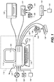
- the present invention is preferably utilized on any well-known computer system, such as a personal computer. Consequently, the computer system will not be discussed in detail herein. It is also instructive to note that the images are either directly input into the computer system (for example by a digital camera) or digitized before input into the computer system (for example by scanning an original, such as a silver halide film).
- the computer system 110 includes a microprocessor-based unit 112 for receiving and processing software programs and for performing other processing functions.
- a display 114 is electrically connected to the microprocessor-based unit 112 for displaying user-related information associated with the software, e.g., by a graphical user interface.
- a keyboard 116 is also connected to the microprocessor based unit 112 for permitting a user to input information to the software.
- a mouse 118 can be used for moving a selector 120 on the display 114 and for selecting an item on which the selector 120 overlays, as is well known in the art.
- a compact disk-read only memory (CD-ROM) 124 which typically includes software programs, is inserted into the microprocessor based unit for providing a way of inputting the software programs and other information to the microprocessor based unit 112.
- a floppy disk 126 can also include a software program, and is inserted into the microprocessor-based unit 112 for inputting the software program.
- the compact disk-read only memory (CD-ROM) 124 or the floppy disk 126 can alternatively be inserted into externally located disk drive unit 122 which is connected to the microprocessor-based unit 112.
- the microprocessor-based unit 112 can be programmed, as is well known in the art, for storing the software program internally.
- the microprocessor-based unit 112 can also have a network connection 127, such as a telephone line, to an external network, such as a local area network or the Internet.
- a printer 128 can also be connected to the microprocessor-based unit 112 for printing a hardcopy of the output from the computer system 110.
- Images can also be displayed on the display 114 via a personal computer card (PC card) 130, such as, as it was formerly known, a PCMCIA card (based on the specifications of the Personal Computer Memory Card International Association) which contains digitized images electronically embodied in the PC card 130.
- PC card 130 is ultimately inserted into the microprocessor based unit 112 for permitting visual display of the image on the display 114.
- the PC card 130 can be inserted into an externally located PC card reader 132 connected to the microprocessor-based unit 112.
- Images can also be input via the compact disk-read only memory (CD-ROM) 124, the floppy disk 126, or the network connection 127.
- CD-ROM compact disk-read only memory
- Any images stored in the PC card 130, the floppy disk 126 or the compact disk-read only memory (CD-ROM) 124, or input through the network connection 127, can have been obtained from a variety of sources, such as a digital camera (not shown) or a scanner (not shown). Images can also be input directly from a digital camera 134 via a camera docking port 136 connected to the microprocessor-based unit 112 or directly from the digital camera 134 via a cable connection 138 to the microprocessor-based unit 112 or via a wireless connection 140 to the microprocessor-based unit 112.
- the algorithm can be stored in any of the storage devices heretofore mentioned and applied to images in order to sharpen the images.
- FIG. 2 is a high-level diagram the first portion of a preferred embodiment of the present invention.
- the digital camera 134 is responsible for creating an original digital red-green-blue-panchromatic (RGBP) color filter array (CFA) image 200, also referred to as the digital RGBP CFA image or the RGBP CFA image.
- RGBBP red-green-blue-panchromatic
- CFA color filter array
- cyan-magenta-yellow-panchromatic can be used in place of red-green-blue-panchromatic in the following description.
- the key item is the inclusion of a panchromatic channel. This image is considered to be a sparsely sampled image because each pixel in the image contains only one pixel value of red, green, blue, or panchromatic data.
- a panchromatic image interpolation block 202 produces a reference panchromatic image 204 from the RGBP CFA image 200. At this point in the image processing chain, each color pixel location has an associated panchromatic value and either a red, green, or a blue value. From the RGBP CFA image 200 and the reference panchromatic image 204, an RGB CFA image interpolation block 206 subsequently produces a full-color image 208.
- the panchromatic image interpolation block 202 and the RGB CFA image interpolation block 206 can be performed in any appropriate ways known to those skilled in the art.
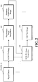
- FIG. 3 is a high-level diagram of the second portion of the preferred embodiment of the present invention.
- a high-frequency panchromatic image generation block 210 produces a high-frequency panchromatic image 212 from the reference panchromatic image 204 ( FIG. 2 ).
- the sharpened full-color image generation block 214 produces a sharpened full-color image 216 from the high-frequency panchromatic image 212 and the full-color image 208 ( FIG. 2 ).
- the high-frequency panchromatic image generation block 210 can be performed in any appropriate way known to those skilled in the art. Two examples are given. The first example is to perform a convolution of the reference panchromatic image 204 ( FIG. 2 ) with the following high-pass convolution kernel to produce the high-frequency panchromatic image 212: 1 16 ⁇ 1 ⁇ 2 ⁇ 1 ⁇ 2 12 ⁇ 2 ⁇ 1 ⁇ 2 ⁇ 1 The second example is to perform a convolution of the reference panchromatic image 204 ( FIG.
- the sharpened full-color image generation block 214 can be performed in any appropriate way known to those skilled in the art.
- the high-frequency panchromatic image 212 is added to the full-color image 208 ( FIG. 2 ) to produce a sharpened full-color image 216.
- FIG. 4 is a high-level diagram of an alternate embodiment of the present invention.
- a high-frequency panchromatic image generation block 218 produces a high-frequency panchromatic image 220 from the reference panchromatic image 204 ( FIG. 2 ).
- a high-frequency panchromatic image modification block 222 produces a modified-high-frequency panchromatic image 224 from a high-frequency panchromatic image 220.
- a sharpened full-color image generation block 226 produces a sharpened full-color image 228 from the modified high-frequency panchromatic image 224 and the full-color image 208 ( FIG. 2 ).
- the high-frequency panchromatic image generation block 218 can be performed in the same way as the high-frequency panchromatic image generation block 210 ( FIG. 3 ).
- the high-frequency panchromatic image modification block 222 can be performed in any appropriate way known to those skilled in the art. As an example, U.S. Patent No. 6,173,085 (Hamilton, Jr. et al. ) teaches the use of a coring function to modify a high-frequency image.
- the sharpened full-color image generation block 226 can be performed in the same way as the sharpened full-color image generation block 214 ( FIG. 3 ).
- FIG. 5 is a high-level diagram of an alternate embodiment of the present invention.
- a high-frequency panchromatic image generation block 230 produces a high-frequency panchromatic image 232 from the reference panchromatic image 204 ( FIG. 2 ).
- a high-frequency panchromatic image modification block 234 produces a modified high-frequency panchromatic image 236 from the high-frequency panchromatic image 232 and the reference panchromatic image 204 ( FIG. 2 ).
- a sharpened full-color image generation block 238 produces a sharpened full-color image 240 from the modified high-frequency panchromatic image 236 and the full-color image 208 ( FIG. 2 ).
- the high-frequency panchromatic image generation block 230 can be performed in the same way as the high-frequency panchromatic image generation block 210 ( FIG. 3 ).
- the high-frequency panchromatic image modification block 234 can be performed in any appropriate way known to those skilled in the art. Examples will be given in subsequent paragraphs.
- the sharpened full-color image generation block 238 can be performed in the same way as the sharpened full-color image generation block 214 ( FIG. 3 ).
- FIG. 6 is a detailed diagram of the high-frequency panchromatic image modification block 234 ( FIG. 5 ).
- An edge mask generation block 242 produces an edge mask 244 from the reference panchromatic image 204 ( FIG. 2 ).
- a high-frequency panchromatic image scaling block 246 produces the modified high-frequency panchromatic image 236 ( FIG. 5 ) from the edge mask 244 and the high-frequency panchromatic image 212 ( FIG. 5 ).
- the edge mask generation block 242 can be performed in any appropriate way known to those skilled in the art.
- the reference panchromatic image 204 ( FIG. 2 ) can be convolved with one or more edge detection convolution kernels and the results combined as a vector norm. Finally, a small bias value can be subtracted from the resulting vector norm to provide a noise-cleaning capability.
- M k
- M is the edge mask 244
- P is the reference panchromatic image 204 ( FIG.
- k is a scaling constant
- b is a predetermined bias constant.
- k is typically set to a value of one-eighth and can be adjusted from that point to increase or decrease the effects of the edge mask.
- To determine an appropriate value for b one typically computes the edge mask with b set to zero and then computes the standard deviation of the edge mask values in a region of P known to be free of scene detail, e.g., a clear sky or a flat wall. b is then set to one or two times the standard deviation.
- the high-frequency panchromatic image scaling block 246 can be performed in any appropriate way known to those skilled in the art. As an example, the edge mask 244 can be multiplied with the high-frequency panchromatic image 212 ( FIG. 5 ) to produce the modified high-frequency panchromatic image 236 ( FIG. 5 ).
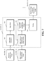
- FIG. 7 is a detailed diagram of an alternate embodiment of the high-frequency panchromatic image modification block 234 ( FIG. 5 ).
- An edge mask generation block 248 produces an edge mask 250 from the reference panchromatic image 204 ( FIG. 2 ).
- a high-frequency panchromatic image scaling block 252 produces a scaled high-frequency panchromatic image 254 from the edge mask 250 and the high-frequency panchromatic image 212 ( FIG. 5 ).
- a coring block 256 produces the modified high-frequency panchromatic image 236 ( FIG. 5 ) from the scaled high-frequency panchromatic image 254.
- the edge mask generation block 248 can be performed in the same way as the edge mask generation block 242 ( FIG. 6 ).
- the high-frequency panchromatic image scaling block 252 can be performed in the same way as the high-frequency panchromatic image scaling block 246 ( FIG. 6 ).
- the coring block 256 can be performed as in the aforementioned reference U.S. Patent No. 6,173,085 (Hamilton, Jr. et al. )
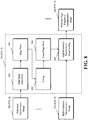
- FIG. 8 is a detailed diagram of an alternate embodiment of the high-frequency panchromatic image modification block 234 ( FIG. 5 ).
- An edge mask generation block 258 produces an edge mask 260 from the reference panchromatic image 204 ( FIG. 2 ).
- a coring block 262 produces a cored edge mask 264 from the edge mask 260.
- a high-frequency panchromatic image scaling block 266 produces the modified high-frequency panchromatic image 236 ( FIG. 5 ) from the cored edge mask 264 and the high-frequency panchromatic image 212 ( FIG. 5 ).
- the edge mask generation block 258 can be performed in the same way as the edge mask generation block 242 ( FIG. 6 ).
- the coring block 262 can be performed in the same way as the coring block 256 ( FIG. 7 ).
- the high-frequency panchromatic image scaling block 266 can be performed in the same way as the high-frequency panchromatic image scaling block 246 ( FIG. 6 ).
- FIG. 9 is a detailed diagram of an alternate embodiment of the high-frequency panchromatic image modification block 234 ( FIG. 5 ).
- An edge mask generation block 268 produces an edge mask 270 from the reference panchromatic image 204 ( FIG. 2 ).
- a coring block 274 produces a cored high-frequency panchromatic image 276 from the high-frequency panchromatic image 212 ( FIG. 5 ).
- a high-frequency panchromatic image scaling block 272 produces the modified high-frequency panchromatic image 236 ( FIG. 5 ) from the edge mask 270 and the cored high-frequency panchromatic image 276.
- the edge mask generation block 268 can be performed in the same way as the edge mask generation block 242 ( FIG. 6 ).
- the coring block 274 can be performed in the same way as the coring block 256 ( FIG. 7 ).
- the high-frequency panchromatic image scaling block 272 can be performed in the same way as the high-frequency panchromatic image scaling block 246 ( FIG. 6 ).
- FIG. 10A is a high-level diagram of an alternate embodiment of the present invention.
- a modify reference panchromatic image block 278 produces a modified reference panchromatic image 280 from the reference panchromatic image 204 ( FIG. 2 ). It will be clear to those skilled in the art that the modified reference panchromatic image 280 can be used in place of the reference panchromatic image 204 ( FIG. 2 ) in any of the previously or subsequently described embodiments of the present invention.
- FIG. 10B is a detailed diagram of the modify reference panchromatic image block 278 ( FIG. 10A ).
- a compute high-frequency panchromatic image block 282 produces a high-frequency panchromatic image 284 from the reference panchromatic image 204 ( FIG. 2 ).
- a coring block 286 produces a cored high-frequency panchromatic image 292 from the high-frequency panchromatic image 284.
- a compute low-frequency panchromatic image block 288 produces a low-frequency panchromatic image 290 from the reference panchromatic image 204 ( FIG. 2 ).
- the generate modified reference panchromatic image block 294 produces the modified reference panchromatic image 280 ( FIG. 10A ) from the cored high-frequency panchromatic image 292 and the low-frequency panchromatic image 290.
- the compute high-frequency panchromatic image block 282 can be performed in the same way as the high-frequency panchromatic image generation block 210 ( FIG. 3 ).
- the coring block 286 can be performed in the same way as the coring block 256 ( FIG. 7 ).
- the compute low-frequency panchromatic image block 288 can be performed in any appropriate way known to those skilled in the art.
- the high-frequency panchromatic image 284 can be subtracted from the reference panchromatic image 204 ( FIG. 2 ) to produce the low-frequency panchromatic image 290.
- a generate modified reference panchromatic image block 294 can be performed in any appropriate way known to those skilled in the art.
- the cored high-frequency panchromatic image 292 can be added to the low-frequency panchromatic image 290 to produce the modified reference panchromatic image 280 ( FIG. 10A ).
- FIG. 11A is a high-level diagram of an alternate embodiment of the present invention.
- a modify reference panchromatic image block 296 produces a modified reference panchromatic image 298 from the reference panchromatic image 204 ( FIG. 2 ). It will be clear to those skilled in the art that the modified reference panchromatic image 298 can be used in place of the reference panchromatic image 204 ( FIG. 2 ) in any of the previously or subsequently described embodiments of the present invention.
- FIG. 11B is a detailed diagram of the modify reference panchromatic image block 296 ( FIG. 11A ).
- a compute low-frequency panchromatic image block 300 produces a low-frequency panchromatic image 302 from the reference panchromatic image 204 ( FIG. 2 ) and a high-frequency panchromatic image 308.
- a compute high-frequency panchromatic image block 306 produces a high-frequency panchromatic image 308 from the reference panchromatic image 204 ( FIG. 2 ).
- a generate edge mask block 312 produces an edge mask 314 from the reference panchromatic image 204 ( FIG. 2 ).
- a mask high-frequency panchromatic image block 310 produces a masked high-frequency panchromatic image 316 from the high-frequency panchromatic image 308 and the edge mask 314.
- a generate modified reference panchromatic image block 304 produces the modified reference panchromatic image 298 ( FIG. 11A ) from the masked high-frequency panchromatic image 316 and the low-frequency panchromatic image 302.
- the compute low-frequency panchromatic image block 300 can be performed in the same way as the compute low-frequency panchromatic image block 288 ( FIG. 10B ).
- the compute high-frequency panchromatic image block 306 can be performed in the same way as the high-frequency panchromatic image generation block 210 ( FIG. 3 ).
- the generate edge mask block 312 can be performed in the same way as the edge mask generation block 242 ( FIG. 6 ).
- the mask high-frequency panchromatic image block 310 can be performed in the same way as the high-frequency panchromatic image scaling block 246 ( FIG. 6 ).
- the generate modified reference panchromatic image block 304 can be performed in the same way as the generate modified reference panchromatic image block 294 ( FIG. 10B ).
- FIG. 12A is a high-level diagram of an alternate embodiment of the present invention.
- a modify reference panchromatic image block 318 produces a modified reference panchromatic image 320 from the reference panchromatic image 204 ( FIG. 2 ). It will be clear to those skilled in the art that the modified reference panchromatic image 320 can be used in place of the reference panchromatic image 204 ( FIG. 2 ) in any of the previously or subsequently described embodiments of the present invention.
- FIG. 12B is a detailed diagram of the modify reference panchromatic image block 318 ( FIG. 12A ).
- a photometric space conversion block 322 produces a modified reference panchromatic image 320 ( FIG. 12A ) from the reference panchromatic image 204 ( FIG. 2 ).
- the photometric space conversion block 322 can be performed in any appropriate way known to those skilled in the art. As an example, U.S. Patent No. 5,708,729 (Adams et al. ) teaches the use of a logarithm and polynomial function to photometrically convert an image.
- FIG. 13 is a high-level diagram of an alternate embodiment of the present invention.
- the modify reference panchromatic image block 278 ( FIG. 10A ) produces a modified reference panchromatic image 324 from the reference panchromatic image 204 ( FIG. 2 ).
- the modify reference panchromatic image 296 ( FIG. 11A ) produces a modified reference panchromatic image 326 from the modified reference panchromatic image 324.
- the modify reference panchromatic image 318 FIG. 12A
- exemplary contexts and environments include, without limitation, wholesale digital photofinishing (which involves exemplary process steps or stages such as film in, digital processing, prints out), retail digital photofinishing (film in, digital processing, prints out), home printing (home scanned film or digital images, digital processing, prints out), desktop software (software that applies algorithms to digital prints to make them better or even just to change them), digital fulfillment (digital images in - from media or over the web, digital processing, with images out - in digital form on media, digital form over the web, or printed on hard-copy prints), kiosks (digital or scanned input, digital processing, digital or scanned output), mobile devices (e.g., PDA or cell phone that can be used as a processing unit, a display unit, or a unit to give processing instructions), and as a service offered via the World Wide Web.
- wholesale digital photofinishing which involves exemplary process steps or stages such as film in, digital processing, prints out
- retail digital photofinishing film in, digital processing, prints out
- home printing home scanned film or digital images, digital
- the sharpening algorithms can stand alone or can be a component of a larger system solution.
- the interfaces with the algorithm e.g., the scanning or input, the digital processing, the display to a user (if needed), the input of user requests or processing instructions (if needed), the output, can each be on the same or different devices and physical locations, and communication between the devices and locations can be via public or private network connections, or media based communication.
- the algorithms themselves can be fully automatic, can have user input (be fully or partially manual), can have user or operator review to accept/reject the result, or can be assisted by metadata (metadata that can be user supplied, supplied by a measuring device (e.g. in a camera), or determined by an algorithm).
- the algorithms can interface with a variety of workflow user interface schemes.
- the sharpening algorithms disclosed herein in accordance with the invention can have interior components that utilize various data detection and reduction techniques (e.g., face detection, eye detection, skin detection, flash detection).
- various data detection and reduction techniques e.g., face detection, eye detection, skin detection, flash detection.
Landscapes
- Physics & Mathematics (AREA)
- General Physics & Mathematics (AREA)
- Engineering & Computer Science (AREA)
- Theoretical Computer Science (AREA)
- Image Processing (AREA)
- Color Television Image Signal Generators (AREA)
Claims (11)
- Verfahren zum Scharfstellen eines Vollfarbbildes einer Szene, umfassend:(a) Erfassen eines Bildes (200) der Szene unter Anwendung einer zweidimensionalen Sensoranordnung, die sowohl Farb- als auch panchromatische Pixel aufweist, wobei das erfasste Bild (200) mit jedem Pixel in dem erfassten Bild spärlich abgetastet wird, das lediglich einen Pixelwert aufweist, der einem jeweiligen von drei Farbkanälen oder einem panchromatischen Kanal zugeordnet ist;(b1) Ausbilden des Vollfarbbildes (208) durch Interpolation der erfassten Farbpixel, wobei jedes Pixel in dem Vollfarbbild (208) drei Pixelwerte aufweist, wobei jeder der drei Pixelwerte einem jeweiligen der drei Farbkanäle zugeordnet ist; und(b2) Ausbilden eines panchromatischen Referenzbildes (204) durch Interpolation der erfassten panchromatischen Pixel, wobei jedes Pixel in dem panchromatischen Referenzbild (204) einen, dem panchromatischen Kanal zugeordneten Pixelwert aufweist;(c) Ausbilden eines panchromatischen Hochfrequenzbildes (212) aus dem panchromatischen Referenzbild (204); und(d) Bereitstellen eines scharfgestellten Vollfarbbildes (216) aus dem panchromatischen Hochfrequenzbild (212) und dem Vollfarbbild (208) durch Hinzufügen des panchromatischen Hochfrequenzbildes (212) zu dem Vollfarbbild (208).
- Verfahren nach Anspruch 1, ferner umfassend ein Modifizieren des panchromatischen Hochfrequenzbildes vor einem Verwenden eines derartigen panchromatischen Bildes in Schritt (d).
- Verfahren nach Anspruch 2, wobei die Modifizierung ferner ein Zentrieren des panchromatischen Hochfrequenzbildes umfasst.
- Verfahren nach Anspruch 2, wobei die Modifizierung ferner auf das panchromatische Referenzbild anspricht.
- Verfahren nach Anspruch 4, wobei die Modifizierung ferner ein Ausbilden einer Kantenmaske und ein Herstellen des modifizierten panchromatischen Hochfrequenzbildes als Reaktion auf die Kantenmaske umfasst.
- Verfahren nach Anspruch 4, wobei die Modifizierung ferner ein Ausbilden einer Kantenmaske und ein Zentrieren und Herstellen des modifizierten panchromatischen Hochfrequenzbildes als Reaktion auf die Kantenmaske und das Zentrieren umfasst.
- Verfahren nach Anspruch 1, ferner umfassend ein Modifizieren des panchromatischen Referenzbildes zur Herstellung eines modifizierten panchromatischen Referenzbildes.
- Verfahren nach Anspruch 7, wobei die Modifizierung des panchromatischen Referenzbildes ein Zentrieren umfasst.
- Verfahren nach Anspruch 7, wobei die Modifizierung des panchromatischen Referenzbildes ein Ausbilden einer Kantenmaske und ein Herstellen des modifizierten panchromatischen Referenzbildes als Reaktion auf die Kantenmaske umfasst.
- Verfahren nach Anspruch 7, wobei die Modifizierung des panchromatischen Referenzbildes eine photometrische Umwandlung umfasst.
- Verfahren nach Anspruch 7, wobei die Modifizierung des panchromatischen Referenzbildes ein Ausbilden einer Kantenmaske, ein Zentrieren und eine photometrische Umwandlung und ein Herstellen des modifizierten panchromatischen Referenzbildes als Reaktion auf die Kantenmaske, das Zentrieren und die photometrische Umwandlung umfasst.
Applications Claiming Priority (2)
| Application Number | Priority Date | Filing Date | Title |
|---|---|---|---|
| US11/621,139 US7769241B2 (en) | 2007-01-09 | 2007-01-09 | Method of sharpening using panchromatic pixels |
| PCT/US2007/025355 WO2008085248A2 (en) | 2007-01-09 | 2007-12-12 | Method of sharpening using panchromatic pixels |
Publications (2)
| Publication Number | Publication Date |
|---|---|
| EP2102815A2 EP2102815A2 (de) | 2009-09-23 |
| EP2102815B1 true EP2102815B1 (de) | 2018-10-24 |
Family
ID=39585115
Family Applications (1)
| Application Number | Title | Priority Date | Filing Date |
|---|---|---|---|
| EP07853342.9A Active EP2102815B1 (de) | 2007-01-09 | 2007-12-12 | Verfahren zur verschärfung unter verwendung panchromatischer pixel |
Country Status (5)
| Country | Link |
|---|---|
| US (1) | US7769241B2 (de) |
| EP (1) | EP2102815B1 (de) |
| JP (1) | JP5260552B2 (de) |
| TW (1) | TWI430202B (de) |
| WO (1) | WO2008085248A2 (de) |
Families Citing this family (24)
| Publication number | Priority date | Publication date | Assignee | Title |
|---|---|---|---|---|
| US7844127B2 (en) * | 2007-03-30 | 2010-11-30 | Eastman Kodak Company | Edge mapping using panchromatic pixels |
| US8594451B2 (en) * | 2007-03-30 | 2013-11-26 | Omnivision Technologies, Inc. | Edge mapping incorporating panchromatic pixels |
| US8896712B2 (en) * | 2007-07-20 | 2014-11-25 | Omnivision Technologies, Inc. | Determining and correcting for imaging device motion during an exposure |
| US8350952B2 (en) * | 2008-06-04 | 2013-01-08 | Omnivision Technologies, Inc. | Image sensors with improved angle response |
| US8130278B2 (en) * | 2008-08-01 | 2012-03-06 | Omnivision Technologies, Inc. | Method for forming an improved image using images with different resolutions |
| KR101574733B1 (ko) * | 2008-11-19 | 2015-12-04 | 삼성전자 주식회사 | 고화질 컬러 영상을 획득하기 위한 영상 처리 장치 및 방법 |
| US8224082B2 (en) * | 2009-03-10 | 2012-07-17 | Omnivision Technologies, Inc. | CFA image with synthetic panchromatic image |
| US8237831B2 (en) * | 2009-05-28 | 2012-08-07 | Omnivision Technologies, Inc. | Four-channel color filter array interpolation |
| US8253832B2 (en) * | 2009-06-09 | 2012-08-28 | Omnivision Technologies, Inc. | Interpolation for four-channel color filter array |
| US8737733B1 (en) * | 2011-04-22 | 2014-05-27 | Digitalglobe, Inc. | Hyperspherical pan sharpening |
| US8761506B1 (en) | 2011-04-22 | 2014-06-24 | DigitalGlobe, Incorporated | Pan sharpening digital imagery |
| WO2012148919A2 (en) | 2011-04-25 | 2012-11-01 | Skybox Imaging, Inc. | Systems and methods for overhead imaging and video |
| JP5900273B2 (ja) * | 2012-10-03 | 2016-04-06 | 株式会社ソシオネクスト | 合焦評価値生成装置、合焦評価値生成方法、及び、合焦評価値生成プログラム |
| CN103198463B (zh) * | 2013-04-07 | 2014-08-27 | 北京航空航天大学 | 基于整体结构和空间细节信息融合的光谱图像全色锐化方法 |
| US10230925B2 (en) | 2014-06-13 | 2019-03-12 | Urthecast Corp. | Systems and methods for processing and providing terrestrial and/or space-based earth observation video |
| KR101580585B1 (ko) * | 2014-12-02 | 2015-12-28 | 서울시립대학교 산학협력단 | 전정색영상과 적외선영상의 융합 방법 및 장치 |
| CA2980920C (en) | 2015-03-25 | 2023-09-26 | King Abdulaziz City Of Science And Technology | Apparatus and methods for synthetic aperture radar with digital beamforming |
| CA2990063A1 (en) | 2015-06-16 | 2017-03-16 | King Abdulaziz City Of Science And Technology | Efficient planar phased array antenna assembly |
| WO2017091747A1 (en) | 2015-11-25 | 2017-06-01 | Urthecast Corp. | Synthetic aperture radar imaging apparatus and methods |
| US11506778B2 (en) | 2017-05-23 | 2022-11-22 | Spacealpha Insights Corp. | Synthetic aperture radar imaging apparatus and methods |
| WO2018217902A1 (en) | 2017-05-23 | 2018-11-29 | King Abdullah City Of Science And Technology | Synthetic aperture radar imaging apparatus and methods for moving targets |
| US10572976B2 (en) | 2017-10-18 | 2020-02-25 | International Business Machines Corporation | Enhancing observation resolution using continuous learning |
| WO2019226194A2 (en) | 2017-11-22 | 2019-11-28 | Urthecast Corp. | Synthetic aperture radar apparatus and methods |
| CN116703769B (zh) * | 2023-06-08 | 2024-03-12 | 福建鼎旸信息科技股份有限公司 | 一种卫星遥感图像全色锐化系统 |
Family Cites Families (22)
| Publication number | Priority date | Publication date | Assignee | Title |
|---|---|---|---|---|
| JPS6339293A (ja) * | 1986-08-05 | 1988-02-19 | Fuji Photo Film Co Ltd | 映像信号形成装置 |
| US5038388A (en) | 1989-05-15 | 1991-08-06 | Polaroid Corporation | Method for adaptively sharpening electronic images |
| US5237402A (en) | 1991-07-30 | 1993-08-17 | Polaroid Corporation | Digital image processing circuitry |
| JP3112531B2 (ja) * | 1991-11-19 | 2000-11-27 | 株式会社日立製作所 | 撮像装置 |
| US5708729A (en) | 1995-04-12 | 1998-01-13 | Eastman Kodak Company | Method and system for the reduction of memory capacity required for digital representation of an image |
| US5949914A (en) * | 1997-03-17 | 1999-09-07 | Space Imaging Lp | Enhancing the resolution of multi-spectral image data with panchromatic image data using super resolution pan-sharpening |
| US6097835A (en) * | 1997-07-23 | 2000-08-01 | Lockheed Martin Corporation | Projective pan sharpening methods and apparatus |
| JP3540567B2 (ja) * | 1997-10-01 | 2004-07-07 | オリンパス株式会社 | 電子的撮像装置 |
| US6011875A (en) * | 1998-04-29 | 2000-01-04 | Eastman Kodak Company | Process for enhancing the spatial resolution of multispectral imagery using pan-sharpening |
| US6529239B1 (en) | 1998-06-01 | 2003-03-04 | Fairchild Imaging, Inc. | Image sensor with stripes of cyan filter material perpendicular to stripes of yellow filter material |
| US6173085B1 (en) | 1998-09-18 | 2001-01-09 | Eastman Kodak Company | Edge enhancement using modified edge boost function |
| AUPQ289099A0 (en) | 1999-09-16 | 1999-10-07 | Silverbrook Research Pty Ltd | Method and apparatus for manipulating a bayer image |
| US6757012B1 (en) | 2000-01-13 | 2004-06-29 | Biomorphic Vlsi, Inc. | Color selection for sparse color image reconstruction |
| US6937774B1 (en) * | 2000-10-24 | 2005-08-30 | Lockheed Martin Corporation | Apparatus and method for efficiently increasing the spatial resolution of images |
| US6813046B1 (en) * | 2000-11-07 | 2004-11-02 | Eastman Kodak Company | Method and apparatus for exposure control for a sparsely sampled extended dynamic range image sensing device |
| US20030222998A1 (en) | 2000-12-20 | 2003-12-04 | Satoru Yamauchi | Digital still camera system and method |
| US7012643B2 (en) | 2002-05-08 | 2006-03-14 | Ball Aerospace & Technologies Corp. | One chip, low light level color camera |
| US7340099B2 (en) * | 2003-01-17 | 2008-03-04 | University Of New Brunswick | System and method for image fusion |
| US7379590B2 (en) * | 2003-01-17 | 2008-05-27 | University Of New Brunswick | Method for generating natural colour satellite images |
| EP1594321A3 (de) | 2004-05-07 | 2006-01-25 | Dialog Semiconductor GmbH | Farbbildaufnahmevorrichtung mit erweitertem Dynamikbereich |
| US7298922B1 (en) * | 2004-07-07 | 2007-11-20 | Lockheed Martin Corporation | Synthetic panchromatic imagery method and system |
| US7667762B2 (en) * | 2006-08-01 | 2010-02-23 | Lifesize Communications, Inc. | Dual sensor video camera |
-
2007
- 2007-01-09 US US11/621,139 patent/US7769241B2/en active Active
- 2007-12-12 EP EP07853342.9A patent/EP2102815B1/de active Active
- 2007-12-12 JP JP2009545537A patent/JP5260552B2/ja active Active
- 2007-12-12 WO PCT/US2007/025355 patent/WO2008085248A2/en not_active Ceased
-
2008
- 2008-01-08 TW TW097100726A patent/TWI430202B/zh active
Non-Patent Citations (4)
| Title |
|---|
| ARMENAKIS C ET AL: "A Comparative Analysis of Image Fusion Methods", 1 June 2005, IEEE TRANSACTIONS ON GEOSCIENCE AND REMOTE SENSING, IEEE SERVICE CENTER, PISCATAWAY, NJ, US, PAGE(S) 1391 - 1402, ISSN: 0196-2892, XP011132522 * |
| MICHAEL E WINTER ET AL: "Physics-based resolution enhancement of hyperspectral data", OPTICAL SENSING II, vol. 4725, 1 August 2002 (2002-08-01), 1000 20th St. Bellingham WA 98225-6705 USA, XP055305654, ISSN: 0277-786X, ISBN: 978-1-62841-971-9, DOI: 10.1117/12.478792 * |
| TE-MING TU ET AL: "A new look at IHS-like image fusion methods", INFORMATION FUSION., vol. 2, no. 3, 1 September 2001 (2001-09-01), US, pages 177 - 186, XP055400550, ISSN: 1566-2535, DOI: 10.1016/S1566-2535(01)00036-7 * |
| TSAI V J D ED - INSTITUTE OF ELECTRICAL AND ELECTRONICS ENGINEERS: "Frequency-based fusion of multiresolution images", LEARNING FROM EARTH'S SHAPES AND SIZES : IGARSS 2003 ; 2003 IEEE INTERNATIONAL GEOSCIENCE AND REMOTE SYMPOSIUM ; CENTRE DE CONGRÈS PIERRE BAUDIS, TOULOUSE, FRANCE, 21 - 25 JULY 2003 ; PROCEEDINGS; [IEEE INTERNATIONAL GEOSCIENCE AND REMOTE SENSING SYM, vol. 6, 21 July 2003 (2003-07-21), pages 3665 - 3667, XP010703755, ISBN: 978-0-7803-7929-9, DOI: 10.1109/IGARSS.2003.1295231 * |
Also Published As
| Publication number | Publication date |
|---|---|
| JP5260552B2 (ja) | 2013-08-14 |
| US20080166062A1 (en) | 2008-07-10 |
| US7769241B2 (en) | 2010-08-03 |
| TWI430202B (zh) | 2014-03-11 |
| WO2008085248A2 (en) | 2008-07-17 |
| EP2102815A2 (de) | 2009-09-23 |
| TW200837658A (en) | 2008-09-16 |
| WO2008085248A3 (en) | 2008-11-13 |
| JP2010516176A (ja) | 2010-05-13 |
Similar Documents
| Publication | Publication Date | Title |
|---|---|---|
| EP2102815B1 (de) | Verfahren zur verschärfung unter verwendung panchromatischer pixel | |
| US7844127B2 (en) | Edge mapping using panchromatic pixels | |
| US8594451B2 (en) | Edge mapping incorporating panchromatic pixels | |
| US7889921B2 (en) | Noise reduced color image using panchromatic image | |
| EP1977613B1 (de) | Interpolation von panchromatischen und farbigen pixeln | |
| EP2089848B1 (de) | Rauschunterdrückung für schwarzweiss- und farbbilder | |
| EP2090092A2 (de) | Bereitstellung eines farbbildes in gewünschter auflösung | |
| WO2009038618A1 (en) | Pixel aspect ratio correction using panchromatic pixels | |
| US20060152596A1 (en) | Noise cleaning sparsely populated color digital images |
Legal Events
| Date | Code | Title | Description |
|---|---|---|---|
| PUAI | Public reference made under article 153(3) epc to a published international application that has entered the european phase |
Free format text: ORIGINAL CODE: 0009012 |
|
| 17P | Request for examination filed |
Effective date: 20090629 |
|
| AK | Designated contracting states |
Kind code of ref document: A2 Designated state(s): AT BE BG CH CY CZ DE DK EE ES FI FR GB GR HU IE IS IT LI LT LU LV MC MT NL PL PT RO SE SI SK TR |
|
| DAX | Request for extension of the european patent (deleted) | ||
| 17Q | First examination report despatched |
Effective date: 20110210 |
|
| RAP1 | Party data changed (applicant data changed or rights of an application transferred) |
Owner name: OMNIVISION TECHNOLOGIES, INC. |
|
| REG | Reference to a national code |
Ref country code: DE Ref legal event code: R079 Ref document number: 602007056626 Country of ref document: DE Free format text: PREVIOUS MAIN CLASS: G06T0005500000 Ipc: G06T0005000000 |
|
| GRAP | Despatch of communication of intention to grant a patent |
Free format text: ORIGINAL CODE: EPIDOSNIGR1 |
|
| RIC1 | Information provided on ipc code assigned before grant |
Ipc: G06T 5/20 20060101ALI20180412BHEP Ipc: G06T 5/50 20060101ALI20180412BHEP Ipc: G06T 5/00 20060101AFI20180412BHEP |
|
| INTG | Intention to grant announced |
Effective date: 20180508 |
|
| GRAS | Grant fee paid |
Free format text: ORIGINAL CODE: EPIDOSNIGR3 |
|
| GRAA | (expected) grant |
Free format text: ORIGINAL CODE: 0009210 |
|
| AK | Designated contracting states |
Kind code of ref document: B1 Designated state(s): AT BE BG CH CY CZ DE DK EE ES FI FR GB GR HU IE IS IT LI LT LU LV MC MT NL PL PT RO SE SI SK TR |
|
| REG | Reference to a national code |
Ref country code: GB Ref legal event code: FG4D |
|
| REG | Reference to a national code |
Ref country code: CH Ref legal event code: EP |
|
| REG | Reference to a national code |
Ref country code: IE Ref legal event code: FG4D |
|
| REG | Reference to a national code |
Ref country code: DE Ref legal event code: R096 Ref document number: 602007056626 Country of ref document: DE Ref country code: AT Ref legal event code: REF Ref document number: 1057569 Country of ref document: AT Kind code of ref document: T Effective date: 20181115 |
|
| REG | Reference to a national code |
Ref country code: NL Ref legal event code: MP Effective date: 20181024 |
|
| REG | Reference to a national code |
Ref country code: LT Ref legal event code: MG4D |
|
| REG | Reference to a national code |
Ref country code: AT Ref legal event code: MK05 Ref document number: 1057569 Country of ref document: AT Kind code of ref document: T Effective date: 20181024 |
|
| PG25 | Lapsed in a contracting state [announced via postgrant information from national office to epo] |
Ref country code: NL Free format text: LAPSE BECAUSE OF FAILURE TO SUBMIT A TRANSLATION OF THE DESCRIPTION OR TO PAY THE FEE WITHIN THE PRESCRIBED TIME-LIMIT Effective date: 20181024 |
|
| PG25 | Lapsed in a contracting state [announced via postgrant information from national office to epo] |
Ref country code: FI Free format text: LAPSE BECAUSE OF FAILURE TO SUBMIT A TRANSLATION OF THE DESCRIPTION OR TO PAY THE FEE WITHIN THE PRESCRIBED TIME-LIMIT Effective date: 20181024 Ref country code: LV Free format text: LAPSE BECAUSE OF FAILURE TO SUBMIT A TRANSLATION OF THE DESCRIPTION OR TO PAY THE FEE WITHIN THE PRESCRIBED TIME-LIMIT Effective date: 20181024 Ref country code: PL Free format text: LAPSE BECAUSE OF FAILURE TO SUBMIT A TRANSLATION OF THE DESCRIPTION OR TO PAY THE FEE WITHIN THE PRESCRIBED TIME-LIMIT Effective date: 20181024 Ref country code: AT Free format text: LAPSE BECAUSE OF FAILURE TO SUBMIT A TRANSLATION OF THE DESCRIPTION OR TO PAY THE FEE WITHIN THE PRESCRIBED TIME-LIMIT Effective date: 20181024 Ref country code: BG Free format text: LAPSE BECAUSE OF FAILURE TO SUBMIT A TRANSLATION OF THE DESCRIPTION OR TO PAY THE FEE WITHIN THE PRESCRIBED TIME-LIMIT Effective date: 20190124 Ref country code: LT Free format text: LAPSE BECAUSE OF FAILURE TO SUBMIT A TRANSLATION OF THE DESCRIPTION OR TO PAY THE FEE WITHIN THE PRESCRIBED TIME-LIMIT Effective date: 20181024 Ref country code: ES Free format text: LAPSE BECAUSE OF FAILURE TO SUBMIT A TRANSLATION OF THE DESCRIPTION OR TO PAY THE FEE WITHIN THE PRESCRIBED TIME-LIMIT Effective date: 20181024 Ref country code: IS Free format text: LAPSE BECAUSE OF FAILURE TO SUBMIT A TRANSLATION OF THE DESCRIPTION OR TO PAY THE FEE WITHIN THE PRESCRIBED TIME-LIMIT Effective date: 20190224 |
|
| PG25 | Lapsed in a contracting state [announced via postgrant information from national office to epo] |
Ref country code: PT Free format text: LAPSE BECAUSE OF FAILURE TO SUBMIT A TRANSLATION OF THE DESCRIPTION OR TO PAY THE FEE WITHIN THE PRESCRIBED TIME-LIMIT Effective date: 20190224 Ref country code: GR Free format text: LAPSE BECAUSE OF FAILURE TO SUBMIT A TRANSLATION OF THE DESCRIPTION OR TO PAY THE FEE WITHIN THE PRESCRIBED TIME-LIMIT Effective date: 20190125 Ref country code: SE Free format text: LAPSE BECAUSE OF FAILURE TO SUBMIT A TRANSLATION OF THE DESCRIPTION OR TO PAY THE FEE WITHIN THE PRESCRIBED TIME-LIMIT Effective date: 20181024 |
|
| REG | Reference to a national code |
Ref country code: DE Ref legal event code: R097 Ref document number: 602007056626 Country of ref document: DE |
|
| PG25 | Lapsed in a contracting state [announced via postgrant information from national office to epo] |
Ref country code: IT Free format text: LAPSE BECAUSE OF FAILURE TO SUBMIT A TRANSLATION OF THE DESCRIPTION OR TO PAY THE FEE WITHIN THE PRESCRIBED TIME-LIMIT Effective date: 20181024 Ref country code: CZ Free format text: LAPSE BECAUSE OF FAILURE TO SUBMIT A TRANSLATION OF THE DESCRIPTION OR TO PAY THE FEE WITHIN THE PRESCRIBED TIME-LIMIT Effective date: 20181024 Ref country code: DK Free format text: LAPSE BECAUSE OF FAILURE TO SUBMIT A TRANSLATION OF THE DESCRIPTION OR TO PAY THE FEE WITHIN THE PRESCRIBED TIME-LIMIT Effective date: 20181024 |
|
| PG25 | Lapsed in a contracting state [announced via postgrant information from national office to epo] |
Ref country code: LU Free format text: LAPSE BECAUSE OF NON-PAYMENT OF DUE FEES Effective date: 20181212 Ref country code: EE Free format text: LAPSE BECAUSE OF FAILURE TO SUBMIT A TRANSLATION OF THE DESCRIPTION OR TO PAY THE FEE WITHIN THE PRESCRIBED TIME-LIMIT Effective date: 20181024 Ref country code: MC Free format text: LAPSE BECAUSE OF FAILURE TO SUBMIT A TRANSLATION OF THE DESCRIPTION OR TO PAY THE FEE WITHIN THE PRESCRIBED TIME-LIMIT Effective date: 20181024 Ref country code: SK Free format text: LAPSE BECAUSE OF FAILURE TO SUBMIT A TRANSLATION OF THE DESCRIPTION OR TO PAY THE FEE WITHIN THE PRESCRIBED TIME-LIMIT Effective date: 20181024 Ref country code: RO Free format text: LAPSE BECAUSE OF FAILURE TO SUBMIT A TRANSLATION OF THE DESCRIPTION OR TO PAY THE FEE WITHIN THE PRESCRIBED TIME-LIMIT Effective date: 20181024 |
|
| PLBE | No opposition filed within time limit |
Free format text: ORIGINAL CODE: 0009261 |
|
| STAA | Information on the status of an ep patent application or granted ep patent |
Free format text: STATUS: NO OPPOSITION FILED WITHIN TIME LIMIT |
|
| REG | Reference to a national code |
Ref country code: IE Ref legal event code: MM4A |
|
| 26N | No opposition filed |
Effective date: 20190725 |
|
| REG | Reference to a national code |
Ref country code: BE Ref legal event code: MM Effective date: 20181231 |
|
| PG25 | Lapsed in a contracting state [announced via postgrant information from national office to epo] |
Ref country code: IE Free format text: LAPSE BECAUSE OF NON-PAYMENT OF DUE FEES Effective date: 20181212 Ref country code: SI Free format text: LAPSE BECAUSE OF FAILURE TO SUBMIT A TRANSLATION OF THE DESCRIPTION OR TO PAY THE FEE WITHIN THE PRESCRIBED TIME-LIMIT Effective date: 20181024 |
|
| PG25 | Lapsed in a contracting state [announced via postgrant information from national office to epo] |
Ref country code: BE Free format text: LAPSE BECAUSE OF NON-PAYMENT OF DUE FEES Effective date: 20181231 |
|
| PG25 | Lapsed in a contracting state [announced via postgrant information from national office to epo] |
Ref country code: MT Free format text: LAPSE BECAUSE OF NON-PAYMENT OF DUE FEES Effective date: 20181212 |
|
| PG25 | Lapsed in a contracting state [announced via postgrant information from national office to epo] |
Ref country code: TR Free format text: LAPSE BECAUSE OF FAILURE TO SUBMIT A TRANSLATION OF THE DESCRIPTION OR TO PAY THE FEE WITHIN THE PRESCRIBED TIME-LIMIT Effective date: 20181024 |
|
| PG25 | Lapsed in a contracting state [announced via postgrant information from national office to epo] |
Ref country code: HU Free format text: LAPSE BECAUSE OF FAILURE TO SUBMIT A TRANSLATION OF THE DESCRIPTION OR TO PAY THE FEE WITHIN THE PRESCRIBED TIME-LIMIT; INVALID AB INITIO Effective date: 20071212 Ref country code: CY Free format text: LAPSE BECAUSE OF FAILURE TO SUBMIT A TRANSLATION OF THE DESCRIPTION OR TO PAY THE FEE WITHIN THE PRESCRIBED TIME-LIMIT Effective date: 20181024 |
|
| PGFP | Annual fee paid to national office [announced via postgrant information from national office to epo] |
Ref country code: CH Payment date: 20250101 Year of fee payment: 18 |
|
| REG | Reference to a national code |
Ref country code: CH Ref legal event code: U11 Free format text: ST27 STATUS EVENT CODE: U-0-0-U10-U11 (AS PROVIDED BY THE NATIONAL OFFICE) Effective date: 20260101 |
|
| PGFP | Annual fee paid to national office [announced via postgrant information from national office to epo] |
Ref country code: DE Payment date: 20251118 Year of fee payment: 19 |
|
| PGFP | Annual fee paid to national office [announced via postgrant information from national office to epo] |
Ref country code: GB Payment date: 20251113 Year of fee payment: 19 |
|
| PGFP | Annual fee paid to national office [announced via postgrant information from national office to epo] |
Ref country code: FR Payment date: 20251111 Year of fee payment: 19 |