EP2102792B1 - Method for optimizing rfid deployment and rfid deployment optimizer of use thereof - Google Patents
Method for optimizing rfid deployment and rfid deployment optimizer of use thereof Download PDFInfo
- Publication number
- EP2102792B1 EP2102792B1 EP07855844.2A EP07855844A EP2102792B1 EP 2102792 B1 EP2102792 B1 EP 2102792B1 EP 07855844 A EP07855844 A EP 07855844A EP 2102792 B1 EP2102792 B1 EP 2102792B1
- Authority
- EP
- European Patent Office
- Prior art keywords
- rfid
- target object
- interrogation zone
- readability
- deployment
- Prior art date
- Legal status (The legal status is an assumption and is not a legal conclusion. Google has not performed a legal analysis and makes no representation as to the accuracy of the status listed.)
- Active
Links
Images





Classifications
-
- G—PHYSICS
- G06—COMPUTING OR CALCULATING; COUNTING
- G06K—GRAPHICAL DATA READING; PRESENTATION OF DATA; RECORD CARRIERS; HANDLING RECORD CARRIERS
- G06K19/00—Record carriers for use with machines and with at least a part designed to carry digital markings
-
- G—PHYSICS
- G01—MEASURING; TESTING
- G01S—RADIO DIRECTION-FINDING; RADIO NAVIGATION; DETERMINING DISTANCE OR VELOCITY BY USE OF RADIO WAVES; LOCATING OR PRESENCE-DETECTING BY USE OF THE REFLECTION OR RERADIATION OF RADIO WAVES; ANALOGOUS ARRANGEMENTS USING OTHER WAVES
- G01S13/00—Systems using the reflection or reradiation of radio waves, e.g. radar systems; Analogous systems using reflection or reradiation of waves whose nature or wavelength is irrelevant or unspecified
- G01S13/74—Systems using reradiation of radio waves, e.g. secondary radar systems; Analogous systems
- G01S13/82—Systems using reradiation of radio waves, e.g. secondary radar systems; Analogous systems wherein continuous-type signals are transmitted
- G01S13/825—Systems using reradiation of radio waves, e.g. secondary radar systems; Analogous systems wherein continuous-type signals are transmitted with exchange of information between interrogator and responder
-
- G—PHYSICS
- G01—MEASURING; TESTING
- G01R—MEASURING ELECTRIC VARIABLES; MEASURING MAGNETIC VARIABLES
- G01R33/00—Arrangements or instruments for measuring magnetic variables
- G01R33/20—Arrangements or instruments for measuring magnetic variables involving magnetic resonance
- G01R33/28—Details of apparatus provided for in groups G01R33/44 - G01R33/64
- G01R33/32—Excitation or detection systems, e.g. using radio frequency signals
-
- G—PHYSICS
- G01—MEASURING; TESTING
- G01S—RADIO DIRECTION-FINDING; RADIO NAVIGATION; DETERMINING DISTANCE OR VELOCITY BY USE OF RADIO WAVES; LOCATING OR PRESENCE-DETECTING BY USE OF THE REFLECTION OR RERADIATION OF RADIO WAVES; ANALOGOUS ARRANGEMENTS USING OTHER WAVES
- G01S7/00—Details of systems according to groups G01S13/00, G01S15/00, G01S17/00
- G01S7/02—Details of systems according to groups G01S13/00, G01S15/00, G01S17/00 of systems according to group G01S13/00
- G01S7/40—Means for monitoring or calibrating
- G01S7/4004—Means for monitoring or calibrating of parts of a radar system
-
- G—PHYSICS
- G06—COMPUTING OR CALCULATING; COUNTING
- G06V—IMAGE OR VIDEO RECOGNITION OR UNDERSTANDING
- G06V30/00—Character recognition; Recognising digital ink; Document-oriented image-based pattern recognition
- G06V30/10—Character recognition
- G06V30/22—Character recognition characterised by the type of writing
- G06V30/224—Character recognition characterised by the type of writing of printed characters having additional code marks or containing code marks
Definitions
- the present invention relates to RFID (Radio Frequency Identification) apparatus, especially to the deployment of RFID apparatus.
- RFID Radio Frequency Identification
- RFID Radio Frequency Identification
- the RFID-detect ranking system includes a matrix subsystem configured to construct a matrix of experiments based on product information, RFID reader information and RFID tag information.
- the RFID-detect ranking system also includes a data collection subsystem configured to facilitate an experiment and collect data to fill in results for each category of the matrix of experiments.
- the RFID-detect ranking system still further includes a ranking subsystem configured to assign an index based on the results for each category of the matrix of experiments, thereby providing a likelihood of success of reading an RFID tag located on a product with an RFID reader.
- the objective of the present invention is to provide a method for optimizing RFID deployment and a RFID deployment optimizer of use thereof.
- the said method and the said RFID deployment optimizer are capable of quickly collecting and analyzing large amount of useful data related to readability of RFID tag in various deployment alternatives so as to enable to optimize RFID deployment in the interrogation zone of the deployed RFID apparatus.
- the present invention provides a method as set out in claim 1.
- the plurality of RFID tags are simultaneously placed at a subset of n x m (n>1, m>1) spots which cover the interrogation zone equally.
- each set of placements for placing RFID tag comprises the position and the orientation of the RFID tag.
- three sets of position may be defined as the front of the target object, the side of the target object and the corner of the target object; at the same time two sets of orientation which could be applied in each position are defined as vertical and horizontal.
- the above method for deployment of RFID apparatus further includes the step of graphically displaying the readability of the at least one RFID tag associated with each set of placements. More preferably, the readability of RFID tag associated with each set of placement is displayed in a form of line chart against time.
- the present invention provides a RFID deployment optimizer as set out in claim 8 for use in the above method for deployment of RFID apparatus that includes RFID antenna and RFID tag.
- the visualizer of the above RFID deployment optimizer further displays the readability of RFID tag in a form of line chart for detailing the readability of RFID tag against time associated with one set of placement.
- the method provided by the present invention includes the following steps:
- the step A is necessary since it is framed with real line.
- the purpose of the step A is to collect testing RFID reading data of the interrogation zone around the gateway and analyze the performance of the interrogation zone based on the RFID reading data.
- the interrogation zone (or called read zone, read field, reader field etc,) is the area in which a RFID antenna can provide enough energy to request a RFID tag and receive response back from the RFID tag, while RFID tags outside the interrogation zone can not receive enough energy from the RFID antenna to reflect back a response.
- the step A further includes the following sub-steps:
- FIG.2 illustrates placement of the at least one RFID antenna in accordance with the step A-1
- FIG.3 illustrates placement of the at leat one RFID tag in accordance with the step A-2.
- a gateway mounting with three antennas is located at one side of the gateway and the height of antennas is 30cm, 100cm and 145cm representatively.
- a 7 ⁇ 15 matrix is defined to make out spots for placing RFID tag and the matrix cover the interrogation zone equally with 25cm separation of each spot.
- the present invention hereby speeds up the analysis by testing a line of fifteen spots simultaneously.
- the analysis is carried out by a line of fifteen RFID tags, and thereby the number of testing is reduced from 7 ⁇ 15 to 7.
- seven testing associated with different sets of placement are performed with different distance between the RFID tags and the RFID antennas starting from 25cm to 175cm with 25cm interval. Every testing have been tested by ten trials and each trial composes 100 interactions (involving requests and response) testing between each RFID antenna and each RFID tag.
- the readability of RFID tag at each particular spot is defined as the percentage of successful interactions (i.e. the number of responses over the number of requests) associated with the trial.
- the readability of RFID tag at each particular spot is determined by the average of the readability of RFID tag for the ten trials.
- the extreme values (involving the maximum and minimum readability of RFID tag) for the ten trials is eliminated, and then the readability of RFID tag at each particular spot is determined by the average of the readability of RFID tag for the reminding values.
- Table. 1 shows an analysis result of the interrogation zone in accordance with the step A illustrated in FIG.1 .
- the first rows of the Table.1 indicates the different position of the RFID tag alone the line of fifteen RFID tags; the first column of the Table.1 indicates the perpendicular distance between the RFID tag and the RFID antenna; and the readability of RFID tag at each spot within the defined interrogation zone is shown associated with particular spot location information. At the same time, the spots with readability of RFID tag over 90% are highlighted in grey color.
- step D visualizes the interrogation zone with detailed environmental information such as the size of the interrogation zone, the shape of the interrogation zone, the best deploying spot in the interrogation zone, the worst deploying spot in the interrogation zone, and etc.
- step D (framed with broken line as shown in FIG. 1 ) facilitates the detection of the best deployment alternatives relatively.
- the analysis result of the interrogation zone attained in the step A is displayed in a form of contour map.
- the readability of RFID tag at each spot within the defined interrogation zone is indicated by different grey scales.
- the size and shape of the interrogation zone can be easily read out from the FIG.4 , and the best or the worst deploying spot of RFID tag within the interrogation zone also can be detected out clearly.
- the analysis result of the interrogation zone attained in the step A is displayed in a form of surface diagram similarly.
- the step B is necessary since it is framed with real line.
- the purpose of the step B is to identify the readability of RFID tag associated with different sets of placement on the target object while the target object is presented inside the interrogation zone.
- the RFID tag is attached on the target object according to experience. If the RFID tag can be read by the RFID antenna associated with one set of placement, then the set of placement will be selected as the solution of the RFID deployment.
- the performance of the selected RFID deployment alternative is unstable due to diverse environmental factors of the interrogation zone and/or various material of the target object, and the RFID reading accuracy of the whole RFID-based system may be very poor ultimately.
- the present invention details the step B by the following sub-steps as shown in FIG.1 :
- FIG.6 illustrates placement of RFID antenna in accordance with the step B-1
- FIG.7-A to FIG7-F illustrates six sets of placement for placing RFID tag in accordance with the step B-2.
- a gateway mounting with three antennas is located at one side of the gateway and the height of antennas is 30cm, 100cm and 145cm representatively.
- the RFID tag is attached on the target object (a carton, a pallet, or etc.) associated with different sets of placement, and RFID reading data concerned with readability of RFID tag is captured in real time while the target object is dynamically passing through the gateway.
- each set of placement for placing RFID tag comprises the position and the orientation of the RFID tag. More detailed, three sets of position are defined as the front of the target object, the side of the target object and the corner of the target object; at the same time two sets of orientation which could be applied in each position are defined as vertical and horizontal.
- FIG.7-A the position is corner and the orientation is vertical for the first set; as shown in FIG.7-B , the position is corner and the orientation is horizontal for the first set; as shown in FIG.7-C , the position is side and the orientation is vertical for the first set; as shown in FIG.7-D , the position is side and the orientation is horizontal for the first set; as shown in FIG.7-E , the position is front and the orientation is vertical for the first set; and as shown in FIG.7-F , the position is front and the orientation is horizontal for the first set.
- a forklift truck with a pallet is passing through the gateway at 5km/hr in accordance with the step B-3.
- the best position and orientation for placing the RFID tag could be determined.
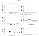
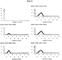
- the step E (framed with broken line) is preferable to graphically visualize the readability of RFID tag associated with each set of placement which is measured in the step B. And more preferably, the readability of RFID tag associated with each set of placement is displayed in a form of line chart against time as shown in FIG.8 to FIG. 12 .
- the x-axis represents the different interaction between the RFID antenna and the RFID tag while the y-axis represents the number of responses from the RFID tag detected by the antenna, hence the line chart indicating the readability of RFID tag against time.
- the shape of the curve indicates the readability of RFID tag while the RFID tag passes through the gateway.
- FIG.8 illustrates line charts of the readability of RFID tag associated with the fifth set of placements illustrated in FIG.7-E while the FIG.9 illustrates line charts of the readability of RFID tag associated with the sixth set of placements illustrated in FIG.7-F . And it is visible that the readability of RFID tag associate with horizontal orientation is better than vertical orientation by the above comparison.
- the FIG.10 illustrates line charts of the readability of RFID tag associated with the first set of placements illustrated in FIG.7-A
- the FIG. 11 illustrates line charts of the readability of RFID tag associated with the third set of placements illustrated in FIG.7-C
- the FIG.12 illustrates line charts of the readability of RFID tag associated with the fifth set of placements illustrated in FIG.7-E . And it is visible that the front position is poorest.
- an embodiment of the RFID deployment optimizer 100 provided by the present invention comprises a RFID middleware 110, a database 120, an analyzer 130, an optimizer 140 and a visualizer 150.
- the RFID middleware 110 communicates with the RFID apparatus 900 and sends RFID reading data to the database 120.
- the database 120 stores the RFID reading data associated with different RFID deployment alternatives.
- the analyzer 130 analyzes the RFID reading data stored in the database 120 to produce corresponding performance associated with different RFID deployment alternatives.
- the analyzer 130 comprises an interrogation zone analysis unit (IZA) 131 for analyzing the interrogation zone where the RFID apparatus are deployed, and a tag placement analysis unit (TPA) 132 for identifying the readability of RFID tag associated with different sets of placement in the interrogation zone.
- IZA interrogation zone analysis unit
- TPA tag placement analysis unit
- the optimizer 140 connects with the analyzer 130 for selecting the best RFID deployment alternative based on all the performances associated with different RFID deployment alternatives. And the optimizer 140 is mainly running for operating the step C illustrated in FIG.1 .
- the visualizer 150 connects with the analyzer 130 for displaying the analysis result outputted by the analyzer 130 graphically. And the visualizer 150 is mainly running for operating the step D and E illustrated in FIG. 1 .
- the described RFID deployment optimizer and method can also be applied to find out the best combinations of hardware such as different readers and tags of different vendors.
- the described RFID deployment optimizer and method can be applied immediately to on-site testing before RFID deployment.
- the present invention can help the companies to find the best deployment and avoid pitfalls quickly and automatically.
Landscapes
- Engineering & Computer Science (AREA)
- Radar, Positioning & Navigation (AREA)
- Remote Sensing (AREA)
- Physics & Mathematics (AREA)
- General Physics & Mathematics (AREA)
- Computer Networks & Wireless Communication (AREA)
- Theoretical Computer Science (AREA)
- Computer Vision & Pattern Recognition (AREA)
- Multimedia (AREA)
- Condensed Matter Physics & Semiconductors (AREA)
- Radar Systems Or Details Thereof (AREA)
- Near-Field Transmission Systems (AREA)
Description
- The present invention relates to RFID (Radio Frequency Identification) apparatus, especially to the deployment of RFID apparatus.
- Since the adoption of Radio Frequency Identification (RFID) by major retailers in US and Europe, many vendors and suppliers have been trying to integrate RFID into their production and distribution processes. However, because of different factors and uncertainties, RFID is usually implemented without 100% accuracy. There is not a systematical method to be used to find out a best solution for the RFID deployment in regard to the conformance and performance of the RFID deployment. Traditionally the deployment setup and configuration can only be evaluated and optimized by trial and error, and consequently the design of the RFID deployment is also carried out by trial and error.
- On the other hand, most companies may set up the RFID apparatus with neglect of the environmental factors and only reference to the specification of the RFID apparatus. For example, if an RFID system requires 3 meter read range as claimed in the specification, an RFID interrogators (or called RFID reader or controller, etc.) and antennas may be used and set up. However, due to different environment factors, the read range may be reduced or enhanced. If the deployment plan is set based on the specification and trial or error of RFID apparatus products, the performance of the deployment is difficult to be guaranteed and expected, and it may become the failure factor of RFID-based project.
-
US Patent Publication No. 2006/0212141 discloses a radio frequency identification (RFID)-detect ranking system and method of operating the same. In one embodiment, the RFID-detect ranking system includes a matrix subsystem configured to construct a matrix of experiments based on product information, RFID reader information and RFID tag information. The RFID-detect ranking system also includes a data collection subsystem configured to facilitate an experiment and collect data to fill in results for each category of the matrix of experiments. The RFID-detect ranking system still further includes a ranking subsystem configured to assign an index based on the results for each category of the matrix of experiments, thereby providing a likelihood of success of reading an RFID tag located on a product with an RFID reader. - In addition to understand the deployment site, companies should also consider the correct tagging placement to ensure the reading performance. Since different material of the target object and the nature of the contained matters affect the RFID performance, it is also difficult to search for an optimal position for different tagging placements on different target objects or product SKU.
- In view of the problem of the prior art, the objective of the present invention is to provide a method for optimizing RFID deployment and a RFID deployment optimizer of use thereof. The said method and the said RFID deployment optimizer are capable of quickly collecting and analyzing large amount of useful data related to readability of RFID tag in various deployment alternatives so as to enable to optimize RFID deployment in the interrogation zone of the deployed RFID apparatus.
- In order to attain the above objective, in one aspect, the present invention provides a method as set out in
claim 1. - Preferably, the plurality of RFID tags are simultaneously placed at a subset of n x m (n>1, m>1) spots which cover the interrogation zone equally.
- For the above method, preferably each set of placements for placing RFID tag comprises the position and the orientation of the RFID tag. In more detail, three sets of position may be defined as the front of the target object, the side of the target object and the corner of the target object; at the same time two sets of orientation which could be applied in each position are defined as vertical and horizontal.
- Preferably, the above method for deployment of RFID apparatus further includes the step of graphically displaying the readability of the at least one RFID tag associated with each set of placements. More preferably, the readability of RFID tag associated with each set of placement is displayed in a form of line chart against time.
- In another aspect, the present invention provides a RFID deployment optimizer as set out in
claim 8 for use in the above method for deployment of RFID apparatus that includes RFID antenna and RFID tag. - Preferably, the visualizer of the above RFID deployment optimizer further displays the readability of RFID tag in a form of line chart for detailing the readability of RFID tag against time associated with one set of placement.
- These and other features, aspects, and embodiments of the invention are described below in the section entitled "Detailed description of the invention."
-
-
FIG. 1 is a flow chart of a method for optimizing the deployment of RFID apparatus in accordance with an embodiment of the present invention; -
FIG.2 illustrates placement of RFID antenna in accordance with the step A-1 illustrated inFIG.1 ; -
FIG.3 illustrates placement of RFID tag in accordance with the step A-2 illustrated inFIG.1 ; -
FIG.4 illustrates the analysis result of the interrogation zone in a form of contour map in accordance with the step D illustrated inFIG.1 ; -
Fig.5 illustrates the analysis result of the interrogation zone in a form of surface diagram in accordance with the step D illustrated inFIG.1 ; -
FIG.6 illustrates placement of RFID antenna in accordance with the step B-1 illustrated inFIG.1 ; -
FIG.7-A illustrates the first set of placement for placing RFID tag in accordance with the step B-2 illustrated inFIG.1 ; -
FIG.7-B illustrates the second set of placement for placing RFID tag in accordance with the step B-2 illustrated inFIG.1 ; -
FIG.7-C illustrates the third set of placement for placing RFID tag in accordance with the step B-2 illustrated inFIG.1 ; -
FIG.7-D illustrates the fourth set of placement for placing RFID tag in accordance with the step B-2 illustrated inFIG.1 ; -
FIG.7-E illustrates the fifth set of placement for placing RFID tag in accordance with the step B-2 illustrated inFIG.1 ; -
FIG.7-F illustrates the sixth set of placement for placing RFID tag in accordance with the step B-2 illustrated inFIG.1 ; -
FIG.8 illustrates line charts of the readability of RFID tag associated with the fifth set of placements illustrated inFIG.7-E ; -
FIG.9 illustrates line charts of the readability of RFID tag associated with the sixth set of placements illustrated inFIG.7-F ; -
FIG.10 illustrates line charts of the readability of RFID tag associated with the first set of placements illustrated inFIG.7-A ; -
FIG. 11 illustrates line charts of the readability of RFID tag associated with the third set of placements illustrated inFIG.7-C ; -
FIG.12 illustrates line charts of the readability of RFID tag associated with the fifth set of placements illustrated inFIG.7-E ; -
FIG.13 illustrates a RFID deployment optimizer in accordance with an embodiment of the present invention. - As shown in
FIG.1 , the method provided by the present invention includes the following steps: - A. analyzing the interrogation zone (or called read zone, read field, and reader field, etc.) where the RFID apparatus are deployed;
- D. displaying the analysis result of the interrogation zone graphically in at least one dimension under different spots of view;
- B. identifying the readability of RFID tag associated with different sets of placement on a target object inside the interrogation zone;
- E. displaying the readability of RFID tag associated with each set of placement graphically; and
- C. selecting the best deployment alternative based on the analysis result of the interrogation zone attained in the step A and all the readabilities of RFID tag identified in the step B.
- Wherein, the step A is necessary since it is framed with real line. The purpose of the step A is to collect testing RFID reading data of the interrogation zone around the gateway and analyze the performance of the interrogation zone based on the RFID reading data. The interrogation zone (or called read zone, read field, reader field etc,) is the area in which a RFID antenna can provide enough energy to request a RFID tag and receive response back from the RFID tag, while RFID tags outside the interrogation zone can not receive enough energy from the RFID antenna to reflect back a response. As shown in
FIG.1 , the step A further includes the following sub-steps: - A-1. placing at least one RFID antenna around the gateway of the interrogation zone;
- A-2. placing at least one RFID tag in the interrogation zone associated with a set of placement;
- A-3. recording the percentage of successful interactions between each of the at least one RFID antenna and each of the at least one RFID tag associated with the set of placement;
and then repeating the step A-2 and A-3 associated with another set of placement. -
FIG.2 illustrates placement of the at least one RFID antenna in accordance with the step A-1, andFIG.3 illustrates placement of the at leat one RFID tag in accordance with the step A-2. - As shown in
FIG.2 , a gateway mounting with three antennas is located at one side of the gateway and the height of antennas is 30cm, 100cm and 145cm representatively. - As shown in
FIG.3 , in order to analyze the interrogation zone of a 2m gateway, a 7×15 matrix is defined to make out spots for placing RFID tag and the matrix cover the interrogation zone equally with 25cm separation of each spot. - In order to understand the performance of the whole interrogation zone, all the spots of the matrix have to be tested. Since the spots are tested one by one traditionally, the environmental factors of the interrogation zone may be inconsistent during the long testing time and as a result the accuracy of the analysis result would not be guaranteed. In order to guarantee the accuracy of the analysis result, the present invention hereby speeds up the analysis by testing a line of fifteen spots simultaneously.
- As shown in
FIG.3 , the analysis is carried out by a line of fifteen RFID tags, and thereby the number of testing is reduced from 7×15 to 7. In other words, seven testing associated with different sets of placement are performed with different distance between the RFID tags and the RFID antennas starting from 25cm to 175cm with 25cm interval. Every testing have been tested by ten trials and each trial composes 100 interactions (involving requests and response) testing between each RFID antenna and each RFID tag. - The number of requests and responses are recorded. For every trial, the readability of RFID tag at each particular spot is defined as the percentage of successful interactions (i.e. the number of responses over the number of requests) associated with the trial. And for the analysis of the interrogation zone, the readability of RFID tag at each particular spot is determined by the average of the readability of RFID tag for the ten trials.
- In addition, in order to further remove testing noise and smooth analysis result, the extreme values (involving the maximum and minimum readability of RFID tag) for the ten trials is eliminated, and then the readability of RFID tag at each particular spot is determined by the average of the readability of RFID tag for the reminding values.
- The following Table. 1 shows an analysis result of the interrogation zone in accordance with the step A illustrated in
FIG.1 . The first rows of the Table.1 indicates the different position of the RFID tag alone the line of fifteen RFID tags; the first column of the Table.1 indicates the perpendicular distance between the RFID tag and the RFID antenna; and the readability of RFID tag at each spot within the defined interrogation zone is shown associated with particular spot location information. At the same time, the spots with readability of RFID tag over 90% are highlighted in grey color.
- For showing the analysis result attained in the step A more vividly, as show in
FIG.1 , the step D visualizes the interrogation zone with detailed environmental information such as the size of the interrogation zone, the shape of the interrogation zone, the best deploying spot in the interrogation zone, the worst deploying spot in the interrogation zone, and etc. As a result, step D (framed with broken line as shown inFIG. 1 ) facilitates the detection of the best deployment alternatives relatively. - For example, as shown in
FIG.4 , the analysis result of the interrogation zone attained in the step A is displayed in a form of contour map. The readability of RFID tag at each spot within the defined interrogation zone is indicated by different grey scales. At the same time, the size and shape of the interrogation zone can be easily read out from theFIG.4 , and the best or the worst deploying spot of RFID tag within the interrogation zone also can be detected out clearly. While for another example, as shown inFIG.5 , the analysis result of the interrogation zone attained in the step A is displayed in a form of surface diagram similarly. - As shown in
FIG.1 , the step B is necessary since it is framed with real line. The purpose of the step B is to identify the readability of RFID tag associated with different sets of placement on the target object while the target object is presented inside the interrogation zone. - Typically, the RFID tag is attached on the target object according to experience. If the RFID tag can be read by the RFID antenna associated with one set of placement, then the set of placement will be selected as the solution of the RFID deployment. However, the performance of the selected RFID deployment alternative is unstable due to diverse environmental factors of the interrogation zone and/or various material of the target object, and the RFID reading accuracy of the whole RFID-based system may be very poor ultimately.
- In order to not only figure out which set of placement can be read within the interrogation zone, but also to provide a quantitative and qualitative measure on the readability of RFID tag within the interrogation zone, the present invention details the step B by the following sub-steps as shown in
FIG.1 : - B-1. placing at least one RFID antenna around the gateway of the interrogation zone;
- B-2. placing at least one RFID tag on the target object associated with one set of placement;
- B-3. capturing the RFID reading data while the target object is passing through the gateway of the interrogation zone, and identifying the readability of RFID tag associated with the set of placement based on the RFID reading data;
and then repeating the step B-2 and B-3 associated with another set of placement. -
FIG.6 illustrates placement of RFID antenna in accordance with the step B-1, andFIG.7-A to FIG7-F illustrates six sets of placement for placing RFID tag in accordance with the step B-2. - As shown in
FIG.6 , a gateway mounting with three antennas is located at one side of the gateway and the height of antennas is 30cm, 100cm and 145cm representatively. - The RFID tag is attached on the target object (a carton, a pallet, or etc.) associated with different sets of placement, and RFID reading data concerned with readability of RFID tag is captured in real time while the target object is dynamically passing through the gateway. And each set of placement for placing RFID tag comprises the position and the orientation of the RFID tag. More detailed, three sets of position are defined as the front of the target object, the side of the target object and the corner of the target object; at the same time two sets of orientation which could be applied in each position are defined as vertical and horizontal.
- As a result, there are six sets of placement for placing RFID tag totally: as shown in
FIG.7-A , the position is corner and the orientation is vertical for the first set; as shown inFIG.7-B , the position is corner and the orientation is horizontal for the first set; as shown inFIG.7-C , the position is side and the orientation is vertical for the first set; as shown inFIG.7-D , the position is side and the orientation is horizontal for the first set; as shown inFIG.7-E , the position is front and the orientation is vertical for the first set; and as shown inFIG.7-F , the position is front and the orientation is horizontal for the first set. - To measure the readability of RFID tag associated with each set of placement, a forklift truck with a pallet is passing through the gateway at 5km/hr in accordance with the step B-3. By comparing the readability of RFID tag associated with each sets of placement, the best position and orientation for placing the RFID tag could be determined.
- As shown in
FIG.1 , the step E (framed with broken line) is preferable to graphically visualize the readability of RFID tag associated with each set of placement which is measured in the step B. And more preferably, the readability of RFID tag associated with each set of placement is displayed in a form of line chart against time as shown inFIG.8 to FIG. 12 . Wherein the x-axis represents the different interaction between the RFID antenna and the RFID tag while the y-axis represents the number of responses from the RFID tag detected by the antenna, hence the line chart indicating the readability of RFID tag against time. Furthermore, the shape of the curve indicates the readability of RFID tag while the RFID tag passes through the gateway. - For comparing the readability of RFID tag associated with different orientations, the
FIG.8 illustrates line charts of the readability of RFID tag associated with the fifth set of placements illustrated inFIG.7-E while theFIG.9 illustrates line charts of the readability of RFID tag associated with the sixth set of placements illustrated inFIG.7-F . And it is visible that the readability of RFID tag associate with horizontal orientation is better than vertical orientation by the above comparison. - Similarly, for comparing the readability of RFID tag associated with different positions, the
FIG.10 illustrates line charts of the readability of RFID tag associated with the first set of placements illustrated inFIG.7-A , theFIG. 11 illustrates line charts of the readability of RFID tag associated with the third set of placements illustrated inFIG.7-C , while theFIG.12 illustrates line charts of the readability of RFID tag associated with the fifth set of placements illustrated inFIG.7-E . And it is visible that the front position is poorest. - As shown in
FIG.13 , an embodiment of theRFID deployment optimizer 100 provided by the present invention comprises aRFID middleware 110, adatabase 120, ananalyzer 130, anoptimizer 140 and avisualizer 150. - The
RFID middleware 110 communicates with theRFID apparatus 900 and sends RFID reading data to thedatabase 120. - The
database 120 stores the RFID reading data associated with different RFID deployment alternatives. - The
analyzer 130 analyzes the RFID reading data stored in thedatabase 120 to produce corresponding performance associated with different RFID deployment alternatives. Theanalyzer 130 comprises an interrogation zone analysis unit (IZA) 131 for analyzing the interrogation zone where the RFID apparatus are deployed, and a tag placement analysis unit (TPA) 132 for identifying the readability of RFID tag associated with different sets of placement in the interrogation zone. And theIZA 131 is mainly running during the operation of the step A-3 illustrated inFIG.1 , while theTPA 132 is mainly running during the operation of the step B-3 illustrated inFIG.1 . - The
optimizer 140 connects with theanalyzer 130 for selecting the best RFID deployment alternative based on all the performances associated with different RFID deployment alternatives. And theoptimizer 140 is mainly running for operating the step C illustrated inFIG.1 . - The
visualizer 150 connects with theanalyzer 130 for displaying the analysis result outputted by theanalyzer 130 graphically. And thevisualizer 150 is mainly running for operating the step D and E illustrated inFIG. 1 . - The main advantages of the RFID deployment optimizer provided by the present invention are:
- Firstly, the described RFID deployment optimizer and the method can quickly detect and collect large amount of useful data related to the environmental effect and deployment considerations. With these data, rich information about the RFID performance in different deployment alternatives will be analyzed and quantitative and qualitative measure will be provided. And thus deployment alternatives with poor performance will be avoided and overall RFID deployment performance and accuracy will be enhanced and guaranteed.
- Secondly, the described RFID deployment optimizer and method can also be applied to find out the best combinations of hardware such as different readers and tags of different vendors.
- Thirdly, the described RFID deployment optimizer and method can be applied immediately to on-site testing before RFID deployment. Particularly, when a deployment of RFID costs thousands to millions, the present invention can help the companies to find the best deployment and avoid pitfalls quickly and automatically.
- The embodiments and examples set forth herein were presented in order to best explain the present invention and its particular application so as enable those skilled in the art to make and use the invention. However, those skilled in the art will recognize that the foregoing description and examples have been presented for the purposes of illustration and example only. The description as set forth is not intended to be exhaustive or to limit the invention to the precise form disclosed. Many modifications and variations are possible in light of the above teaching. The extent of protection is determined by the following claims.
Claims (10)
- A method for deployment of RFID apparatus that comprises an RFID antenna and an RFID tag, the method comprising:analyzing (A) an interrogation zone where the RFID apparatus is deployed on the basis of interactions between at least one RFID antenna and a plurality of RFID tags by
placing at least one RFID antenna around a gateway of the interrogation zone,
placing a plurality of RFID tags in the interrogation zone at a set of placement locations,
simultaneously recording a readability defined as the percentage of successful interactions between each of the at least one RFID antenna and each of the plurality of RFID tags, and
repeating the placing and recording for one or more further sets of placement locations for the plurality of RFID tags;displaying (D) the result of the analysis of the interactions graphically as a contour map or surface diagram for detailing the size and shape of the interrogation zone and/or various deployment spots in the interrogation zone;identifying (B), while the target object is passing through the gateway, the readability of at least one RFID tag at different sets of placement locations on a target object; andselecting (C) a deployment alternative based on a result of the analysis of the interactions and on the readability of the at least one RFID tag on the target object. - The method as claimed in claim 1, wherein the plurality of RFID tags are placed at n x m spots which cover the interrogation zone equally, n>1 and m>1.
- The method as claimed in claim 2, wherein the set of placement locations comprises a line of m RFID tags in the interrogation zone.
- The method as claimed in claim 1, wherein identifying the readability of the at least one RFID tag on the target object comprises:placing at least one RFID antenna around the gateway of the interrogation zone;placing one or more RFID tags on the target object at respective one or more locations associated with one of the different sets of placement locations;capturing RFID reading data from the one or more RFID tags while the target object is passing through the gateway of the interrogation zone, and identifying the readability of one or more RFID tags; andrepeating the placing and capturing for one or more further sets of placement locations on the target object.
- The method as claimed in 4, wherein the set of placement locations on the target object and the further sets of placement locations on the target object include different positions and/or orientations of the one or more RFID tags on the target object.
- The method as claimed in either claim 4 or claim 5, further comprising, between identifying and selecting, displaying (E) the readability of the one or more RFID tags associated with each set of placement locations on the target object graphically.
- The method as claimed in claim 6, wherein the readability of the one or more RFID tags associated with each set of placement locations on the target object is displayed as
a line chart against time. - A RFID deployment optimizer for optimizing the deployment of RFID apparatus that includes an RFID antenna and an RFID tag, comprising
a RFID middleware (110) configured to communicate with the RFID apparatus and to send RFID reading data to the database;
a database (120) coupled to the middleware and configured to store the RFID reading data associated with different RFID deployment alternatives, where the RFID apparatus is deployed with at least one RFID antenna around a gateway of an interrogation zone and a plurality of RFID tags in the interrogation zone at a plurality of sets of placement locations;
an analyzer configured to analyze the RFID reading data to produce corresponding performance information associated with the different RFID deployment alternatives, the analyzer comprising
an interrogation zone analysis unit (131) configured to analyze (A) an interrogation zone where the RFID apparatus is deployed on the basis of a readability defined as the percentage of successful interactions between each of the at least one RFID antenna and each of the plurality of RFID tags simultaneously recorded for each set of placement locations in the interrogation zone, and
a tag placement analysis unit (132) configured to identify, while the target object is passing through the gateway, the readability of at least one RFID tag on a target object; and
an optimizer (140) coupled to the analyzer and configured to select an RFID deployment alternative based on the performance information associated with the different RFID deployment alternatives; and
a visualizer (150) configured to graphically display the performance information from the analyzer as a contour map or a surface diagram for detailing the size and shape of the interrogation zone and/or various deployment spots in the interrogation zone. - The RFID deployment optimizer as claimed in claim 8, wherein the tag placement analysis unit (132) is further configured to identify the readability of at least one RFID tag on the target object by analyzing reading data communicated from one or more RFID tags placed on the target object at respective one or more locations associated with a plurality of sets of placement locations, the reading data being captured from the one or more RFID tags while the target object is passing through the gateway of the interrogation zone.
- The RFID deployment optimizer as claimed in claim 9, wherein the visualizer (150) is configured to display the readability of that at least one RFID tag as a line chart for detailing the readability of the at least one RFID tag against time associated with a set of placement locations on the target object.
Applications Claiming Priority (2)
| Application Number | Priority Date | Filing Date | Title |
|---|---|---|---|
| HK06114212A HK1095702A2 (en) | 2006-12-28 | 2006-12-28 | Method for optimizing rfid deployment and rfid deployment optimizer of use thereof |
| PCT/CN2007/003843 WO2008086703A1 (en) | 2006-12-28 | 2007-12-27 | Method for optimizing rfid deployment and rfid deployment optimizer of use thereof |
Publications (3)
| Publication Number | Publication Date |
|---|---|
| EP2102792A1 EP2102792A1 (en) | 2009-09-23 |
| EP2102792A4 EP2102792A4 (en) | 2009-12-23 |
| EP2102792B1 true EP2102792B1 (en) | 2017-05-31 |
Family
ID=38047400
Family Applications (1)
| Application Number | Title | Priority Date | Filing Date |
|---|---|---|---|
| EP07855844.2A Active EP2102792B1 (en) | 2006-12-28 | 2007-12-27 | Method for optimizing rfid deployment and rfid deployment optimizer of use thereof |
Country Status (7)
| Country | Link |
|---|---|
| US (1) | US8325012B2 (en) |
| EP (1) | EP2102792B1 (en) |
| JP (2) | JP2010515132A (en) |
| KR (1) | KR101259669B1 (en) |
| CN (2) | CN101636746A (en) |
| HK (1) | HK1095702A2 (en) |
| WO (1) | WO2008086703A1 (en) |
Families Citing this family (3)
| Publication number | Priority date | Publication date | Assignee | Title |
|---|---|---|---|---|
| JP5708378B2 (en) * | 2011-08-30 | 2015-04-30 | 株式会社リコー | RFID evaluation system |
| CN116803012B (en) * | 2021-01-29 | 2026-01-20 | 华为技术有限公司 | A method and apparatus for wireless communication |
| CN115460615B (en) * | 2022-09-06 | 2024-07-23 | 广西大学 | A RFID antenna optimization deployment method based on brainstorming algorithm |
Family Cites Families (13)
| Publication number | Priority date | Publication date | Assignee | Title |
|---|---|---|---|---|
| JP4731060B2 (en) * | 2001-07-31 | 2011-07-20 | トッパン・フォームズ株式会社 | RF-ID inspection method and inspection system |
| US7084769B2 (en) * | 2002-01-09 | 2006-08-01 | Vue Technology, Inc. | Intelligent station using multiple RF antennae and inventory control system and method incorporating same |
| JP2005135354A (en) * | 2003-10-08 | 2005-05-26 | Toshiba Tec Corp | Radio tag reading apparatus, radio tag module used in the apparatus, article with radio tag, and storage box for storing the article |
| US7667575B2 (en) * | 2004-07-30 | 2010-02-23 | Reva Systems Corporation | Location virtualization in an RFID system |
| US7614555B2 (en) * | 2004-09-09 | 2009-11-10 | The Gillette Company | RFID sensor array |
| US20060082444A1 (en) * | 2004-10-19 | 2006-04-20 | Alysis Interactive Corporation | Management system for enhanced RFID system performance |
| US7164353B2 (en) | 2004-12-22 | 2007-01-16 | Avery Dennison Corporation | Method and system for testing RFID devices |
| JP4575434B2 (en) * | 2005-02-15 | 2010-11-04 | 三菱電機株式会社 | Reader control device and control program |
| US20060212141A1 (en) * | 2005-02-25 | 2006-09-21 | Abraham Thomas C Jr | Radio frequency identification-detect ranking system and method of operating the same |
| JP5002907B2 (en) * | 2005-04-15 | 2012-08-15 | オムロン株式会社 | Information processing apparatus and method |
| EP1724596B1 (en) | 2005-05-17 | 2011-02-23 | Electronics and Telecommunications Research Institute | Apparatus for measuring read range between RFID tag and reader |
| US7602288B2 (en) * | 2005-12-01 | 2009-10-13 | Frito-Lay North America, Inc. | Method for slap-and-ship RFID labeling |
| US7154283B1 (en) * | 2006-02-22 | 2006-12-26 | Avery Dennison Corporation | Method of determining performance of RFID devices |
-
2006
- 2006-12-28 HK HK06114212A patent/HK1095702A2/en not_active IP Right Cessation
-
2007
- 2007-12-27 JP JP2009543331A patent/JP2010515132A/en active Pending
- 2007-12-27 KR KR1020097012969A patent/KR101259669B1/en active Active
- 2007-12-27 CN CN200780048348A patent/CN101636746A/en active Pending
- 2007-12-27 CN CN201210192947.8A patent/CN102968603B/en not_active Expired - Fee Related
- 2007-12-27 EP EP07855844.2A patent/EP2102792B1/en active Active
- 2007-12-27 US US12/521,394 patent/US8325012B2/en active Active
- 2007-12-27 WO PCT/CN2007/003843 patent/WO2008086703A1/en not_active Ceased
-
2012
- 2012-12-06 JP JP2012267197A patent/JP5771592B2/en active Active
Also Published As
| Publication number | Publication date |
|---|---|
| US8325012B2 (en) | 2012-12-04 |
| KR20090098836A (en) | 2009-09-17 |
| JP5771592B2 (en) | 2015-09-02 |
| US20100289621A1 (en) | 2010-11-18 |
| CN102968603B (en) | 2016-03-16 |
| EP2102792A1 (en) | 2009-09-23 |
| JP2013054777A (en) | 2013-03-21 |
| CN102968603A (en) | 2013-03-13 |
| KR101259669B1 (en) | 2013-05-09 |
| EP2102792A4 (en) | 2009-12-23 |
| CN101636746A (en) | 2010-01-27 |
| HK1095702A2 (en) | 2007-05-11 |
| WO2008086703A1 (en) | 2008-07-24 |
| JP2010515132A (en) | 2010-05-06 |
Similar Documents
| Publication | Publication Date | Title |
|---|---|---|
| US8031070B2 (en) | Automated system for producing location-based inventories | |
| JP7662088B2 (en) | Information processing device, information processing method, and program | |
| Ergen et al. | Tracking and locating components in a precast storage yard utilizing radio frequency identification technology and GPS | |
| JP4900609B2 (en) | Method for assigning and estimating the position of an article detected by a multi-RFID antenna | |
| US20090219157A1 (en) | Apparatus and methods for placing radio frequency identification (rfid) antennas, tags, and/or interrogators | |
| CN102783157A (en) | Customer and vehicle dynamic grouping | |
| KR20130137071A (en) | Systems and methods for detecting patterns in spatio-temporal data collected using an rfid system | |
| US12062013B1 (en) | Automated planogram generation and usage | |
| JP7130945B2 (en) | Inventory detection program, inventory detection method and inventory detection device | |
| US8325012B2 (en) | Method for optimizing RFID deployment and RFID deployment optimizer of use thereof | |
| AU2025203776A1 (en) | Methods and apparatus for machine learning system for edge computer vision and active reality | |
| JPWO2007029321A1 (en) | Checkout system, checkout system control program, and checkout system control method | |
| KR101533360B1 (en) | Logistics management and order picking system for information visualization objects and method therefor | |
| CN110415464A (en) | The method and apparatus for identifying commodity by multiple force snesor | |
| US20250322352A1 (en) | Method for tracking and updating product data for slots in inventory structures within a store | |
| JP4747622B2 (en) | Information processing apparatus, information processing method, control program, recording medium recording control program, and information processing system | |
| CN114140776B (en) | Article distribution identification method, apparatus, electronic device and readable storage medium | |
| JP7564075B2 (en) | Work support device and work support method | |
| CN110109945A (en) | Applied to the AOI detection method of substrate, device, storage medium and AOI detection device | |
| CN117022963A (en) | A method, storage medium and equipment for sorting goods | |
| CN111797951A (en) | Point inspection method, point inspection device, computer readable storage medium and computer equipment | |
| JPH09179903A (en) | Article information analysis system for virtual store drawing | |
| JP2005092376A (en) | Product display shelf and its operation system | |
| JP2004078632A (en) | Customer trend survey system | |
| NAWOYA | IoT based monitoring system for authorized retail freezer contents for beverage companies |
Legal Events
| Date | Code | Title | Description |
|---|---|---|---|
| PUAI | Public reference made under article 153(3) epc to a published international application that has entered the european phase |
Free format text: ORIGINAL CODE: 0009012 |
|
| 17P | Request for examination filed |
Effective date: 20090626 |
|
| AK | Designated contracting states |
Kind code of ref document: A1 Designated state(s): AT BE BG CH CY CZ DE DK EE ES FI FR GB GR HU IE IS IT LI LT LU LV MC MT NL PL PT RO SE SI SK TR |
|
| RIN1 | Information on inventor provided before grant (corrected) |
Inventor name: NG, PUI HIM Inventor name: TAN, BURLY K. Inventor name: LEE, WING BUN Inventor name: CHEUNG, CHI FAI Inventor name: KWOK, SIU KEUNG Inventor name: HO, SZE KIT Inventor name: TSANG, HING CHOI |
|
| A4 | Supplementary search report drawn up and despatched |
Effective date: 20091125 |
|
| DAX | Request for extension of the european patent (deleted) | ||
| 17Q | First examination report despatched |
Effective date: 20101201 |
|
| REG | Reference to a national code |
Ref country code: DE Ref legal event code: R079 Ref document number: 602007051198 Country of ref document: DE Free format text: PREVIOUS MAIN CLASS: G06K0009180000 Ipc: G01S0007400000 |
|
| RIC1 | Information provided on ipc code assigned before grant |
Ipc: G01S 7/40 20060101AFI20161026BHEP Ipc: G01S 13/82 20060101ALI20161026BHEP |
|
| GRAP | Despatch of communication of intention to grant a patent |
Free format text: ORIGINAL CODE: EPIDOSNIGR1 |
|
| INTG | Intention to grant announced |
Effective date: 20161214 |
|
| RIN1 | Information on inventor provided before grant (corrected) |
Inventor name: TSANG, HING CHOI Inventor name: HO, SZE KIT Inventor name: NG, PUI HIM Inventor name: KWOK, SIU KEUNG Inventor name: TAN, BURLY K. Inventor name: LEE, WING BUN Inventor name: CHEUNG, CHI FAI |
|
| GRAS | Grant fee paid |
Free format text: ORIGINAL CODE: EPIDOSNIGR3 |
|
| GRAA | (expected) grant |
Free format text: ORIGINAL CODE: 0009210 |
|
| AK | Designated contracting states |
Kind code of ref document: B1 Designated state(s): AT BE BG CH CY CZ DE DK EE ES FI FR GB GR HU IE IS IT LI LT LU LV MC MT NL PL PT RO SE SI SK TR |
|
| REG | Reference to a national code |
Ref country code: CH Ref legal event code: EP Ref country code: GB Ref legal event code: FG4D |
|
| REG | Reference to a national code |
Ref country code: AT Ref legal event code: REF Ref document number: 897962 Country of ref document: AT Kind code of ref document: T Effective date: 20170615 |
|
| REG | Reference to a national code |
Ref country code: FR Ref legal event code: PLFP Year of fee payment: 11 |
|
| REG | Reference to a national code |
Ref country code: IE Ref legal event code: FG4D |
|
| REG | Reference to a national code |
Ref country code: DE Ref legal event code: R096 Ref document number: 602007051198 Country of ref document: DE |
|
| REG | Reference to a national code |
Ref country code: NL Ref legal event code: MP Effective date: 20170531 |
|
| REG | Reference to a national code |
Ref country code: LT Ref legal event code: MG4D |
|
| REG | Reference to a national code |
Ref country code: AT Ref legal event code: MK05 Ref document number: 897962 Country of ref document: AT Kind code of ref document: T Effective date: 20170531 |
|
| PG25 | Lapsed in a contracting state [announced via postgrant information from national office to epo] |
Ref country code: ES Free format text: LAPSE BECAUSE OF FAILURE TO SUBMIT A TRANSLATION OF THE DESCRIPTION OR TO PAY THE FEE WITHIN THE PRESCRIBED TIME-LIMIT Effective date: 20170531 Ref country code: AT Free format text: LAPSE BECAUSE OF FAILURE TO SUBMIT A TRANSLATION OF THE DESCRIPTION OR TO PAY THE FEE WITHIN THE PRESCRIBED TIME-LIMIT Effective date: 20170531 Ref country code: FI Free format text: LAPSE BECAUSE OF FAILURE TO SUBMIT A TRANSLATION OF THE DESCRIPTION OR TO PAY THE FEE WITHIN THE PRESCRIBED TIME-LIMIT Effective date: 20170531 Ref country code: LT Free format text: LAPSE BECAUSE OF FAILURE TO SUBMIT A TRANSLATION OF THE DESCRIPTION OR TO PAY THE FEE WITHIN THE PRESCRIBED TIME-LIMIT Effective date: 20170531 Ref country code: GR Free format text: LAPSE BECAUSE OF FAILURE TO SUBMIT A TRANSLATION OF THE DESCRIPTION OR TO PAY THE FEE WITHIN THE PRESCRIBED TIME-LIMIT Effective date: 20170901 |
|
| PG25 | Lapsed in a contracting state [announced via postgrant information from national office to epo] |
Ref country code: BG Free format text: LAPSE BECAUSE OF FAILURE TO SUBMIT A TRANSLATION OF THE DESCRIPTION OR TO PAY THE FEE WITHIN THE PRESCRIBED TIME-LIMIT Effective date: 20170831 Ref country code: IS Free format text: LAPSE BECAUSE OF FAILURE TO SUBMIT A TRANSLATION OF THE DESCRIPTION OR TO PAY THE FEE WITHIN THE PRESCRIBED TIME-LIMIT Effective date: 20170930 Ref country code: SE Free format text: LAPSE BECAUSE OF FAILURE TO SUBMIT A TRANSLATION OF THE DESCRIPTION OR TO PAY THE FEE WITHIN THE PRESCRIBED TIME-LIMIT Effective date: 20170531 Ref country code: LV Free format text: LAPSE BECAUSE OF FAILURE TO SUBMIT A TRANSLATION OF THE DESCRIPTION OR TO PAY THE FEE WITHIN THE PRESCRIBED TIME-LIMIT Effective date: 20170531 Ref country code: NL Free format text: LAPSE BECAUSE OF FAILURE TO SUBMIT A TRANSLATION OF THE DESCRIPTION OR TO PAY THE FEE WITHIN THE PRESCRIBED TIME-LIMIT Effective date: 20170531 |
|
| PG25 | Lapsed in a contracting state [announced via postgrant information from national office to epo] |
Ref country code: CZ Free format text: LAPSE BECAUSE OF FAILURE TO SUBMIT A TRANSLATION OF THE DESCRIPTION OR TO PAY THE FEE WITHIN THE PRESCRIBED TIME-LIMIT Effective date: 20170531 Ref country code: SK Free format text: LAPSE BECAUSE OF FAILURE TO SUBMIT A TRANSLATION OF THE DESCRIPTION OR TO PAY THE FEE WITHIN THE PRESCRIBED TIME-LIMIT Effective date: 20170531 Ref country code: EE Free format text: LAPSE BECAUSE OF FAILURE TO SUBMIT A TRANSLATION OF THE DESCRIPTION OR TO PAY THE FEE WITHIN THE PRESCRIBED TIME-LIMIT Effective date: 20170531 Ref country code: RO Free format text: LAPSE BECAUSE OF FAILURE TO SUBMIT A TRANSLATION OF THE DESCRIPTION OR TO PAY THE FEE WITHIN THE PRESCRIBED TIME-LIMIT Effective date: 20170531 Ref country code: DK Free format text: LAPSE BECAUSE OF FAILURE TO SUBMIT A TRANSLATION OF THE DESCRIPTION OR TO PAY THE FEE WITHIN THE PRESCRIBED TIME-LIMIT Effective date: 20170531 |
|
| PG25 | Lapsed in a contracting state [announced via postgrant information from national office to epo] |
Ref country code: IT Free format text: LAPSE BECAUSE OF FAILURE TO SUBMIT A TRANSLATION OF THE DESCRIPTION OR TO PAY THE FEE WITHIN THE PRESCRIBED TIME-LIMIT Effective date: 20170531 Ref country code: PL Free format text: LAPSE BECAUSE OF FAILURE TO SUBMIT A TRANSLATION OF THE DESCRIPTION OR TO PAY THE FEE WITHIN THE PRESCRIBED TIME-LIMIT Effective date: 20170531 |
|
| REG | Reference to a national code |
Ref country code: DE Ref legal event code: R097 Ref document number: 602007051198 Country of ref document: DE |
|
| PLBE | No opposition filed within time limit |
Free format text: ORIGINAL CODE: 0009261 |
|
| STAA | Information on the status of an ep patent application or granted ep patent |
Free format text: STATUS: NO OPPOSITION FILED WITHIN TIME LIMIT |
|
| 26N | No opposition filed |
Effective date: 20180301 |
|
| PG25 | Lapsed in a contracting state [announced via postgrant information from national office to epo] |
Ref country code: SI Free format text: LAPSE BECAUSE OF FAILURE TO SUBMIT A TRANSLATION OF THE DESCRIPTION OR TO PAY THE FEE WITHIN THE PRESCRIBED TIME-LIMIT Effective date: 20170531 |
|
| REG | Reference to a national code |
Ref country code: CH Ref legal event code: PL |
|
| REG | Reference to a national code |
Ref country code: IE Ref legal event code: MM4A |
|
| PG25 | Lapsed in a contracting state [announced via postgrant information from national office to epo] |
Ref country code: MT Free format text: LAPSE BECAUSE OF NON-PAYMENT OF DUE FEES Effective date: 20171227 Ref country code: LU Free format text: LAPSE BECAUSE OF NON-PAYMENT OF DUE FEES Effective date: 20171227 |
|
| REG | Reference to a national code |
Ref country code: BE Ref legal event code: MM Effective date: 20171231 |
|
| PG25 | Lapsed in a contracting state [announced via postgrant information from national office to epo] |
Ref country code: IE Free format text: LAPSE BECAUSE OF NON-PAYMENT OF DUE FEES Effective date: 20171227 |
|
| PG25 | Lapsed in a contracting state [announced via postgrant information from national office to epo] |
Ref country code: LI Free format text: LAPSE BECAUSE OF NON-PAYMENT OF DUE FEES Effective date: 20171231 Ref country code: CH Free format text: LAPSE BECAUSE OF NON-PAYMENT OF DUE FEES Effective date: 20171231 Ref country code: BE Free format text: LAPSE BECAUSE OF NON-PAYMENT OF DUE FEES Effective date: 20171231 |
|
| PG25 | Lapsed in a contracting state [announced via postgrant information from national office to epo] |
Ref country code: HU Free format text: LAPSE BECAUSE OF FAILURE TO SUBMIT A TRANSLATION OF THE DESCRIPTION OR TO PAY THE FEE WITHIN THE PRESCRIBED TIME-LIMIT; INVALID AB INITIO Effective date: 20071227 Ref country code: MC Free format text: LAPSE BECAUSE OF FAILURE TO SUBMIT A TRANSLATION OF THE DESCRIPTION OR TO PAY THE FEE WITHIN THE PRESCRIBED TIME-LIMIT Effective date: 20170531 |
|
| PG25 | Lapsed in a contracting state [announced via postgrant information from national office to epo] |
Ref country code: CY Free format text: LAPSE BECAUSE OF NON-PAYMENT OF DUE FEES Effective date: 20170531 |
|
| PG25 | Lapsed in a contracting state [announced via postgrant information from national office to epo] |
Ref country code: TR Free format text: LAPSE BECAUSE OF FAILURE TO SUBMIT A TRANSLATION OF THE DESCRIPTION OR TO PAY THE FEE WITHIN THE PRESCRIBED TIME-LIMIT Effective date: 20170531 |
|
| PG25 | Lapsed in a contracting state [announced via postgrant information from national office to epo] |
Ref country code: PT Free format text: LAPSE BECAUSE OF FAILURE TO SUBMIT A TRANSLATION OF THE DESCRIPTION OR TO PAY THE FEE WITHIN THE PRESCRIBED TIME-LIMIT Effective date: 20170531 |
|
| P01 | Opt-out of the competence of the unified patent court (upc) registered |
Effective date: 20230527 |
|
| PGFP | Annual fee paid to national office [announced via postgrant information from national office to epo] |
Ref country code: DE Payment date: 20251118 Year of fee payment: 19 |
|
| PGFP | Annual fee paid to national office [announced via postgrant information from national office to epo] |
Ref country code: GB Payment date: 20251113 Year of fee payment: 19 |
|
| PGFP | Annual fee paid to national office [announced via postgrant information from national office to epo] |
Ref country code: FR Payment date: 20251111 Year of fee payment: 19 |