EP2102501B1 - Apparatus for adjusting top clearance of reciprocating compressor - Google Patents
Apparatus for adjusting top clearance of reciprocating compressor Download PDFInfo
- Publication number
- EP2102501B1 EP2102501B1 EP06824169.4A EP06824169A EP2102501B1 EP 2102501 B1 EP2102501 B1 EP 2102501B1 EP 06824169 A EP06824169 A EP 06824169A EP 2102501 B1 EP2102501 B1 EP 2102501B1
- Authority
- EP
- European Patent Office
- Prior art keywords
- drive shaft
- top clearance
- conveyance
- pistons
- nut
- Prior art date
- Legal status (The legal status is an assumption and is not a legal conclusion. Google has not performed a legal analysis and makes no representation as to the accuracy of the status listed.)
- Not-in-force
Links
- 230000004044 response Effects 0.000 description 3
- 230000005540 biological transmission Effects 0.000 description 2
- 239000002826 coolant Substances 0.000 description 2
- 238000006073 displacement reaction Methods 0.000 description 2
- 230000008859 change Effects 0.000 description 1
- 230000006835 compression Effects 0.000 description 1
- 238000007906 compression Methods 0.000 description 1
- 238000012423 maintenance Methods 0.000 description 1
- 238000004519 manufacturing process Methods 0.000 description 1
- 230000007246 mechanism Effects 0.000 description 1
- 230000004048 modification Effects 0.000 description 1
- 238000012986 modification Methods 0.000 description 1
- 230000002459 sustained effect Effects 0.000 description 1
Images

Classifications
-
- F—MECHANICAL ENGINEERING; LIGHTING; HEATING; WEAPONS; BLASTING
- F04—POSITIVE - DISPLACEMENT MACHINES FOR LIQUIDS; PUMPS FOR LIQUIDS OR ELASTIC FLUIDS
- F04B—POSITIVE-DISPLACEMENT MACHINES FOR LIQUIDS; PUMPS
- F04B27/00—Multi-cylinder pumps specially adapted for elastic fluids and characterised by number or arrangement of cylinders
- F04B27/08—Multi-cylinder pumps specially adapted for elastic fluids and characterised by number or arrangement of cylinders having cylinders coaxial with, or parallel or inclined to, main shaft axis
- F04B27/10—Multi-cylinder pumps specially adapted for elastic fluids and characterised by number or arrangement of cylinders having cylinders coaxial with, or parallel or inclined to, main shaft axis having stationary cylinders
- F04B27/1036—Component parts, details, e.g. sealings, lubrication
- F04B27/1054—Actuating elements
- F04B27/1063—Actuating-element bearing means or driving-axis bearing means
-
- F—MECHANICAL ENGINEERING; LIGHTING; HEATING; WEAPONS; BLASTING
- F04—POSITIVE - DISPLACEMENT MACHINES FOR LIQUIDS; PUMPS FOR LIQUIDS OR ELASTIC FLUIDS
- F04B—POSITIVE-DISPLACEMENT MACHINES FOR LIQUIDS; PUMPS
- F04B27/00—Multi-cylinder pumps specially adapted for elastic fluids and characterised by number or arrangement of cylinders
- F04B27/08—Multi-cylinder pumps specially adapted for elastic fluids and characterised by number or arrangement of cylinders having cylinders coaxial with, or parallel or inclined to, main shaft axis
- F04B27/0873—Component parts, e.g. sealings; Manufacturing or assembly thereof
- F04B27/0878—Pistons
-
- F—MECHANICAL ENGINEERING; LIGHTING; HEATING; WEAPONS; BLASTING
- F04—POSITIVE - DISPLACEMENT MACHINES FOR LIQUIDS; PUMPS FOR LIQUIDS OR ELASTIC FLUIDS
- F04B—POSITIVE-DISPLACEMENT MACHINES FOR LIQUIDS; PUMPS
- F04B27/00—Multi-cylinder pumps specially adapted for elastic fluids and characterised by number or arrangement of cylinders
- F04B27/08—Multi-cylinder pumps specially adapted for elastic fluids and characterised by number or arrangement of cylinders having cylinders coaxial with, or parallel or inclined to, main shaft axis
- F04B27/10—Multi-cylinder pumps specially adapted for elastic fluids and characterised by number or arrangement of cylinders having cylinders coaxial with, or parallel or inclined to, main shaft axis having stationary cylinders
- F04B27/1036—Component parts, details, e.g. sealings, lubrication
- F04B27/1054—Actuating elements
- F04B27/1072—Pivot mechanisms
-
- F—MECHANICAL ENGINEERING; LIGHTING; HEATING; WEAPONS; BLASTING
- F04—POSITIVE - DISPLACEMENT MACHINES FOR LIQUIDS; PUMPS FOR LIQUIDS OR ELASTIC FLUIDS
- F04B—POSITIVE-DISPLACEMENT MACHINES FOR LIQUIDS; PUMPS
- F04B27/00—Multi-cylinder pumps specially adapted for elastic fluids and characterised by number or arrangement of cylinders
- F04B27/08—Multi-cylinder pumps specially adapted for elastic fluids and characterised by number or arrangement of cylinders having cylinders coaxial with, or parallel or inclined to, main shaft axis
- F04B27/14—Control
- F04B27/16—Control of pumps with stationary cylinders
- F04B27/18—Control of pumps with stationary cylinders by varying the relative positions of a swash plate and a cylinder block
-
- F—MECHANICAL ENGINEERING; LIGHTING; HEATING; WEAPONS; BLASTING
- F04—POSITIVE - DISPLACEMENT MACHINES FOR LIQUIDS; PUMPS FOR LIQUIDS OR ELASTIC FLUIDS
- F04B—POSITIVE-DISPLACEMENT MACHINES FOR LIQUIDS; PUMPS
- F04B49/00—Control, e.g. of pump delivery, or pump pressure of, or safety measures for, machines, pumps, or pumping installations, not otherwise provided for, or of interest apart from, groups F04B1/00 - F04B47/00
- F04B49/12—Control, e.g. of pump delivery, or pump pressure of, or safety measures for, machines, pumps, or pumping installations, not otherwise provided for, or of interest apart from, groups F04B1/00 - F04B47/00 by varying the length of stroke of the working members
-
- F—MECHANICAL ENGINEERING; LIGHTING; HEATING; WEAPONS; BLASTING
- F04—POSITIVE - DISPLACEMENT MACHINES FOR LIQUIDS; PUMPS FOR LIQUIDS OR ELASTIC FLUIDS
- F04B—POSITIVE-DISPLACEMENT MACHINES FOR LIQUIDS; PUMPS
- F04B49/00—Control, e.g. of pump delivery, or pump pressure of, or safety measures for, machines, pumps, or pumping installations, not otherwise provided for, or of interest apart from, groups F04B1/00 - F04B47/00
- F04B49/16—Control, e.g. of pump delivery, or pump pressure of, or safety measures for, machines, pumps, or pumping installations, not otherwise provided for, or of interest apart from, groups F04B1/00 - F04B47/00 by adjusting the capacity of dead spaces of working chambers
-
- F—MECHANICAL ENGINEERING; LIGHTING; HEATING; WEAPONS; BLASTING
- F04—POSITIVE - DISPLACEMENT MACHINES FOR LIQUIDS; PUMPS FOR LIQUIDS OR ELASTIC FLUIDS
- F04B—POSITIVE-DISPLACEMENT MACHINES FOR LIQUIDS; PUMPS
- F04B27/00—Multi-cylinder pumps specially adapted for elastic fluids and characterised by number or arrangement of cylinders
- F04B27/08—Multi-cylinder pumps specially adapted for elastic fluids and characterised by number or arrangement of cylinders having cylinders coaxial with, or parallel or inclined to, main shaft axis
- F04B27/14—Control
- F04B27/16—Control of pumps with stationary cylinders
- F04B27/18—Control of pumps with stationary cylinders by varying the relative positions of a swash plate and a cylinder block
- F04B27/1804—Controlled by crankcase pressure
- F04B2027/1822—Valve-controlled fluid connection
- F04B2027/1827—Valve-controlled fluid connection between crankcase and discharge chamber
Definitions
- the present invention relates to an apparatus for adjusting a top clearance of a reciprocating compressor, and more particularly, to an apparatus for adjusting a top clearance of a reciprocating compressor capable of readily adjusting a top clearance between a bottom surface of a piston and a valve, without the need to disassemble components.
- a reciprocating compressor is composed of a piston, a piston drive apparatus, a cylinder block, and a valve, and widely used in a compressor, a pump, or the like.
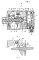
- FIGS. 1A and 1B illustrate a swash plate type compressor disclosed in Korean Patent Registration No. 0519744 , as an example of a reciprocating compressor.
- the conventional variable displacement swash plate type compressor 10 includes a cylinder block 11 having a plurality of cylinder bores 11a arranged in parallel in a longitudinal direction at its inner periphery, a front housing 12 sealed in the front of the cylinder block 11, and a rear housing 13 sealed in the rear of the cylinder block 11 with a valve plate 13a interposed therebetween.
- a crank chamber 14 is disposed inside the front housing 12.
- One end of a drive shaft 15 passing through the crank chamber 14 is rotatably installed at the center of the front housing 12 and the other end of the drive shaft 15 is supported by a bearing 11c at a center shaft hole 11b in the cylinder block 11.
- a lug plate 16 and a swash plate 17 are installed on the drive shaft 15, and a spring 27 is interposed between the lug plate 16 and the swash plate 17 to resiliently support the swash plate 17 against the lug plate 16.
- the lug plate 16 has a pair of power transmission projections 16a each having a straight hinge hole 16b and projecting from one surface thereof to be simultaneously rotated with the drive shaft 15.
- the swash plate 17 is inserted into the drive shaft 15 at a predetermined angle, and hinge pins 18 are inserted into the hinge holes 16b formed at the power transmission projections 16a of the lug plate 16, such that the swash plate 17 rotates with the lug plate 16, causing it to vary in inclination.
- shoes 20 are inserted into an outer periphery of the swash plate 17 to be slidably inserted into pistons 19 disposed in the cylinder bores 11a.
- the rear housing 13 has a suction chamber 21 and a discharge chamber 22.
- the valve plate 13a interposed between the rear housing 13 and the cylinder block 11 has suction ports 23 and discharge ports 24 corresponding to the cylinder bores 11a.
- Each of the suction ports 23 and the discharge ports 24 formed at the valve plate 13a has a suction lid 25 and a discharge lid 26, respectively, which open and close the suction port 23 and the discharge port 24 in response to pressure variation caused by reciprocation of the piston 19.
- the rear housing 13 has a control valve 28 for communicating the crank chamber 14 with the suction chamber 21 such that a difference between a coolant suction pressure in the cylinder bore 11a and a pressure in the crank chamber 14 is varied to adjust inclination of the swash plate 17.
- the conventional variable displacement swash plate type com pressor 10 adjusts inclination of the swash plate 17 in response to the pressure difference between a pressure in the crank chamber 14 and a suction pressure in the cylinder bore 11a, as shown in FIGS. 1A, 1B , and 2 , to adjust a stroke of the piston 19 connected to the swash plate 17 depending on inclination variation of the swash plate 17, thereby varying discharge capacity of the compressor.
- top clearance TC between the valve plate 13a and the piston 19.
- the top clearance TC is necessary to prevent a collision between the piston 19 and the valve plate 13a, it is practical to minimize the top clearance for increased compression efficiency.
- top clearance TC may be adjusted as necessary.
- a thrust bearing 31 having a predetermined width is installed between the cylinder block 11 and the drive shaft 15.
- FIG. 2 illustrates another swash plate type compressor disclosed in Korean Patent Registration No. 0529716 .
- a top clearance is obtained by a bearing 78 interposed between two laces 77.
- the top clearance can be adjusted by changing the thickness of any of the two laces 77.
- a compressor having an apparatus for adjusting as defined in the preamble of claim 1 is know e.g. from US Patent 5,063,829 .
- the above problems can be generated in various reciprocating compressors that are composed of a pump, a piston, a piston drive unit, a valve, a cylinder block, and so on, as well as the aforementioned compressor.
- An object of the present invention is to provide an apparatus for adjusting a top clearance capable of precisely and conveniently adjusting the top clearance on the basis of characteristics of a valve or piston of a reciprocating compressor.
- An aspect of the invention provides an apparatus for adjusting a top clearance of a reciprocating compressor including: a housing, a cylinder block having a plurality of cylinder bores, pistons reciprocally accommodated in the cylinder bores, a piston drive means for driving the pistons, a drive shaft connected to the pistons, suction/discharge valves installed opposite to bottoms of the pistons, and a suction chamber and a discharge chamber formed in the housing through the medium of the suction/discharge valves, characterized in that the drive shaft has a conveyance nut threadedly engaged therearound, and in that when seen in an axial direction of the piston connection shaft, the conveyance nut may have a fixing groove having a plurality of prominences and depressions formed at the center of the conveyance nut in a circumferential direction, a fixing washer having prominences and depressions formed therearound may be installed in the fixing groove, and the fixing washer may pass through the drive shaft.
- the fixing washer may be formed of a resilient thin plate, and may be resiliently inserted into the fixing groove of the conveyance nut.
- the fixing washer may be fastened to the drive shaft in a rotational direction.
- the drive shaft and the fixing washer coupled with the piston connection shaft may be formed in a polygonal shape having round corners or an oval shape.
- the fixing groove of the conveyance nut, with which the fixing washer is coupled, may have a step formed therearound.
- a thrust bearing may be installed in the front or rear of the conveyance nut.
- the drive shaft is a drive shaft rotatably supported by the cylinder block, a swash plate may be installed at the drive shaft to simultaneously rotate with the drive shaft and vary the inclination thereof, and the piston may be reciprocally accommodated in the cylinder bore and be slidable back and forth with respect to the swash plate.
- FIG. 1A is a longitudinal cross-sectional view of a conventional swash plate type compressor
- FIG. 1B is an enlarged view of a top clearance of FIG. 1A ;
- FIG. 2 is a longitudinal cross-sectional view of another conventional swash plate type compressor
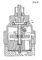
- FIG. 3 is a longitudinal cross-sectional view of a machine having an apparatus for adjusting a top clearance in accordance with an exemplary embodiment of the present invention
- FIG. 4 is an enlarged longitudinal cross-sectional view of the apparatus for adjusting a top clearance of FIG. 3 ;
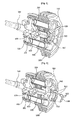
- FIG. 5 is a partial cross-sectional perspective view of FIG. 4 ;
- FIG. 6 is an exploded cross-sectional perspective view of FIG. 4 .
- a reciprocating compressor 1000 in accordance with the present invention includes a housing 100, a cylinder block 110 having a plurality of cylinder bores 110a, a drive shaft 140 rotatably supported by the cylinder block 110, a swash plate 150 connected to the drive shaft 140 and rotatably installed to vary its inclination, pistons 200 reciprocally accommodated in the cylinder bores 110a and capable of sliding back and forth with respect to the swash plate 150, a suction/discharge valve apparatus 300 installed opposite to a bottom surface of the piston 200, and a suction chamber 131 and a discharge chamber 132 formed at the housing 100 through the medium of the suction/discharge valve apparatus 300.
- the housing 100 comprises a front housing 120 and a rear housing 130, interposing the cylinder block 110 therebetween.
- the rear housing 130 has the suction chamber 131 and the discharge chamber 132.
- a valve plate 330 has suction ports 331 for communicating the cylinder bores 110a with the suction chamber 131, and discharge ports 332 for communicating the cylinder bores 110a with the discharge chamber 132.
- suction ports 331 and the discharge ports 332 formed at the valve plate 330 include suction valves and the discharge valves for opening and closing the suction ports 331 and the discharge ports 332 in response to pressure variation depending on reciprocation of the pistons 200, respectively.
- the cylinder block 110 has eight cylinder bores 110a. Coolant introduced from the suction chamber 131 by the pistons 200 reciprocating through the cylinder bores 110a is continuously compressed.
- the drive shaft 140 is rotatably supported by the front housing 120 and the cylinder block 110 via a bearing 400.
- swash plate 150 is slidably coupled with the pistons 200 by shoes 201.
- connection links 600 are interposed between the connection projections 155 and the drive shaft 140, which are connected to each other by hinge pins 610. Therefore, the connection links 600 and the connection projections 155, and the connection links 600 and the drive shaft 140 can be hinged to each other.
- a top clearance adjusting apparatus 500 for adjusting a top clearance between the pistons 200 and the suction/discharge valve apparatus 300 is installed to appropriately adjust the top clearance which varies according to a deviation between the length of the valve or piston, and the length of the cylinder.
- a conveyance nut 510 may be threadedly engaged with the drive shaft 140. Therefore, the drive shaft 140 axially moves depending on rotation of the conveyance nut 510. That is, the conveyance nut 510 becomes a rotating drive part which rotates at the original place, not moving in an axial direction, and the drive shaft 140 becomes a driven rotation part.
- a thrust bearing or an equivalent structure 530 is installed before or after the conveyance nut 510.
- the thrust bearing is selected there is no need to change its specification.
- a conveyance distance per revolution of the conveyance nut 510 should be precisely set. That is, when the top clearance is determined, using the conveyance distance a user can rotate the conveyance nut 510 to precisely adjust the top clearance.
- the conveyance nut 510 is threadedly engaged with the drive shaft 140. Therefore, in order to fix the top clearance, even though the drive shaft is rotated, the conveyance nut 510 should be rotated in a state in which the rotated position is fixed to the drive shaft 140.
- the drive shaft 140 and the conveyance nut 510 require an anti-rotation structure.
- the anti-rotation structure may be a fastening force of the threaded engagement itself which is between the drive shaft 140 and the conveyance nut 510.
- the threaded engagement may loosen due to vibration and load variation of the compressor, and the drive shaft 140 and the conveyance nut 510 may be worn out or damaged under high-speed rotation and heavy load.
- a fixing washer 520 is coupled with the conveyance nut 510 through the drive shaft 140 to be fixed thereto.
- the conveyance nut 510 when seen in an axial direction, includes a fixing groove 511 having a plurality of prominences and depressions 512 formed at the center thereof in a circumferential direction, and the fixing washer 520 has prominences and depressions 522 formed in a circumferential direction thereof to be coupled with the fixing groove 511.
- precision of the top clearance can be determined depending on the number of the prominences and depressions 512 and 522 (in FIG. 4 , fourteen). That is, under the condition that its strength can be sustained, the greater the number of prominences and depressions, the higher the precision of the top clearance.
- the top clearance can be adjusted to the micron unit.
- the fixing washer 520 is made of a resilient hollow thin plate, the fixing washer 520 is resiliently inserted into the fixing groove 511 of the conveyance nut 510 to securely fix the conveyance nut 510.
- the fixing washer 520 should be fixed to the drive shaft 140 without any relative rotation.
- the drive shaft 140 and the fixing washer 520 coupled with the drive shaft 140 have a triangular shape with round corners.
- various shapes of structures for example, a polygonal or oval shape may be employed.
- a step is circumferentially formed at the fixing groove 511 of the conveyance nut 510, with which the fixing washer 520 is coupled, to prevent the conveyance nut 510 from slipping in an axial direction during operation of the compressor.
- Reference symbol P designates a pulley for receiving power from an engine (not shown) through a belt (not shown) to rotate the drive shaft 140.
- the drive shaft 140 When the conveyance nut 510 is rotated counterclockwise along a male thread formed on a surface of the drive shaft 140, the drive shaft 140 is spaced apart from the conveyance nut 510, and the swash plate 150 connected to the drive shaft 140 by the connection links 600, simultaneously moves forward with the pistons 200 linked to the swash plate 150 to increase the top clearance.
- the above-described top clearance adjusting apparatus 500 may be adapted to various reciprocating compressors including a piston, a cylinder block, a valve, and a piston drive unit.
- Various swash plate type or crank-slide link drive type mechanisms using rotational force of an engine may be adapted as the piston drive unit.
- top clearance adjusting apparatus including the conveyance nut and the fixing washer is coupled with the piston connection shaft of the reciprocating compressor such as a pump, as well as the compressor shown in FIGS. 1 and 2 , thereby readily enabling top clearance adjustment.
- top clearance can be precisely adjusted, a dead volume caused by the top clearance can be minimized depending on characteristics of the valve and the piston.
Landscapes
- Engineering & Computer Science (AREA)
- Mechanical Engineering (AREA)
- General Engineering & Computer Science (AREA)
- Manufacturing & Machinery (AREA)
- Compressors, Vaccum Pumps And Other Relevant Systems (AREA)
- Compressor (AREA)
Description
- The present invention relates to an apparatus for adjusting a top clearance of a reciprocating compressor, and more particularly, to an apparatus for adjusting a top clearance of a reciprocating compressor capable of readily adjusting a top clearance between a bottom surface of a piston and a valve, without the need to disassemble components.
- A reciprocating compressor is composed of a piston, a piston drive apparatus, a cylinder block, and a valve, and widely used in a compressor, a pump, or the like.
-
FIGS. 1A and 1B illustrate a swash plate type compressor disclosed in Korean Patent Registration No.0519744 - As shown in
FIG. 1A , the conventional variable displacement swashplate type compressor 10 includes acylinder block 11 having a plurality ofcylinder bores 11a arranged in parallel in a longitudinal direction at its inner periphery, afront housing 12 sealed in the front of thecylinder block 11, and arear housing 13 sealed in the rear of thecylinder block 11 with avalve plate 13a interposed therebetween. - A
crank chamber 14 is disposed inside thefront housing 12. One end of adrive shaft 15 passing through thecrank chamber 14 is rotatably installed at the center of thefront housing 12 and the other end of thedrive shaft 15 is supported by a bearing 11c at acenter shaft hole 11b in thecylinder block 11. - In addition, a
lug plate 16 and aswash plate 17 are installed on thedrive shaft 15, and aspring 27 is interposed between thelug plate 16 and theswash plate 17 to resiliently support theswash plate 17 against thelug plate 16. - The
lug plate 16 has a pair ofpower transmission projections 16a each having astraight hinge hole 16b and projecting from one surface thereof to be simultaneously rotated with thedrive shaft 15. Theswash plate 17 is inserted into thedrive shaft 15 at a predetermined angle, andhinge pins 18 are inserted into thehinge holes 16b formed at thepower transmission projections 16a of thelug plate 16, such that theswash plate 17 rotates with thelug plate 16, causing it to vary in inclination. - Further,
shoes 20 are inserted into an outer periphery of theswash plate 17 to be slidably inserted intopistons 19 disposed in thecylinder bores 11a. - Therefore, as the
swash plate 17 rotates in a tilted state, thepistons 19 inserted into the outer periphery of theswash plate 17 via theshoes 20 reciprocate in thecylinder bores 11a of thecylinder block 11. - In addition, the
rear housing 13 has asuction chamber 21 and adischarge chamber 22. Thevalve plate 13a interposed between therear housing 13 and thecylinder block 11 hassuction ports 23 anddischarge ports 24 corresponding to thecylinder bores 11a. - Each of the
suction ports 23 and thedischarge ports 24 formed at thevalve plate 13a has asuction lid 25 and adischarge lid 26, respectively, which open and close thesuction port 23 and thedischarge port 24 in response to pressure variation caused by reciprocation of thepiston 19. - Further, the
rear housing 13 has acontrol valve 28 for communicating thecrank chamber 14 with thesuction chamber 21 such that a difference between a coolant suction pressure in thecylinder bore 11a and a pressure in thecrank chamber 14 is varied to adjust inclination of theswash plate 17. - As described above, the conventional variable displacement swash plate type com pressor 10 adjusts inclination of the
swash plate 17 in response to the pressure difference between a pressure in thecrank chamber 14 and a suction pressure in thecylinder bore 11a, as shown inFIGS. 1A, 1B , and2 , to adjust a stroke of thepiston 19 connected to theswash plate 17 depending on inclination variation of theswash plate 17, thereby varying discharge capacity of the compressor. - Meanwhile, as shown in
FIG. 1B , there is a top clearance TC between thevalve plate 13a and thepiston 19. Although the top clearance TC is necessary to prevent a collision between thepiston 19 and thevalve plate 13a, it is practical to minimize the top clearance for increased compression efficiency. - In addition, the top clearance TC may be adjusted as necessary.
- In this case, as shown in
FIG. 1A , a thrust bearing 31 having a predetermined width is installed between thecylinder block 11 and thedrive shaft 15. - Therefore, when the top clearance is modified depending on characteristics of the valve or piston, the only solution is to replace the thrust bearing 31. However, the replacement of the thrust bearing 31 requires disassembly of the entire set of components making the operation troublesome.
- Moreover, if there is no fitting thrust bearing to produce the required top clearance, additional costs are incurred to manufacture a separate thrust bearing.
- Meanwhile,
FIG. 2 illustrates another swash plate type compressor disclosed in Korean Patent Registration No.0529716 - In the conventional compressor, a top clearance is obtained by a
bearing 78 interposed between twolaces 77. In this case, the top clearance can be adjusted by changing the thickness of any of the twolaces 77. - However, to precisely adjust the top clearance according to the conventional art,
laces 77 of various thicknesses are needed, thereby causing storage and maintenance difficulties, and complicating assembly. - A compressor having an apparatus for adjusting as defined in the preamble of claim 1 is know e.g. from
US Patent 5,063,829 . The above problems can be generated in various reciprocating compressors that are composed of a pump, a piston, a piston drive unit, a valve, a cylinder block, and so on, as well as the aforementioned compressor. - An object of the present invention is to provide an apparatus for adjusting a top clearance capable of precisely and conveniently adjusting the top clearance on the basis of characteristics of a valve or piston of a reciprocating compressor.
- An aspect of the invention provides an apparatus for adjusting a top clearance of a reciprocating compressor including: a housing, a cylinder block having a plurality of cylinder bores, pistons reciprocally accommodated in the cylinder bores, a piston drive means for driving the pistons, a drive shaft connected to the pistons, suction/discharge valves installed opposite to bottoms of the pistons, and a suction chamber and a discharge chamber formed in the housing through the medium of the suction/discharge valves, characterized in that the drive shaft has a conveyance nut threadedly engaged therearound, and in that when seen in an axial direction of the piston connection shaft, the conveyance nut may have a fixing groove having a plurality of prominences and depressions formed at the center of the conveyance nut in a circumferential direction, a fixing washer having prominences and depressions formed therearound may be installed in the fixing groove, and the fixing washer may pass through the drive shaft.
- The fixing washer may be formed of a resilient thin plate, and may be resiliently inserted into the fixing groove of the conveyance nut.
- The fixing washer may be fastened to the drive shaft in a rotational direction.
- The drive shaft and the fixing washer coupled with the piston connection shaft may be formed in a polygonal shape having round corners or an oval shape.
- The fixing groove of the conveyance nut, with which the fixing washer is coupled, may have a step formed therearound.
- A thrust bearing may be installed in the front or rear of the conveyance nut.
- The drive shaft is a drive shaft rotatably supported by the cylinder block, a swash plate may be installed at the drive shaft to simultaneously rotate with the drive shaft and vary the inclination thereof, and the piston may be reciprocally accommodated in the cylinder bore and be slidable back and forth with respect to the swash plate.
- The above and other objects, features and advantages of the present invention will be more apparent from the following detailed description taken in conjunction with the accompanying drawings, in which:
-
FIG. 1A is a longitudinal cross-sectional view of a conventional swash plate type compressor; -
FIG. 1B is an enlarged view of a top clearance ofFIG. 1A ; -
FIG. 2 is a longitudinal cross-sectional view of another conventional swash plate type compressor; -
FIG. 3 is a longitudinal cross-sectional view of a machine having an apparatus for adjusting a top clearance in accordance with an exemplary embodiment of the present invention; -
FIG. 4 is an enlarged longitudinal cross-sectional view of the apparatus for adjusting a top clearance ofFIG. 3 ; -
FIG. 5 is a partial cross-sectional perspective view ofFIG. 4 ; and -
FIG. 6 is an exploded cross-sectional perspective view ofFIG. 4 . - Hereinafter, exemplary embodiments of the present invention will be described with reference to
FIGS 3 to 6 . - First, a reciprocating
compressor 1000 in accordance with the present invention includes ahousing 100, acylinder block 110 having a plurality ofcylinder bores 110a, adrive shaft 140 rotatably supported by thecylinder block 110, aswash plate 150 connected to thedrive shaft 140 and rotatably installed to vary its inclination,pistons 200 reciprocally accommodated in thecylinder bores 110a and capable of sliding back and forth with respect to theswash plate 150, a suction/discharge valve apparatus 300 installed opposite to a bottom surface of thepiston 200, and asuction chamber 131 and adischarge chamber 132 formed at thehousing 100 through the medium of the suction/discharge valve apparatus 300. - The
housing 100 comprises afront housing 120 and arear housing 130, interposing thecylinder block 110 therebetween. - In addition, the
rear housing 130 has thesuction chamber 131 and thedischarge chamber 132. Avalve plate 330 hassuction ports 331 for communicating thecylinder bores 110a with thesuction chamber 131, anddischarge ports 332 for communicating thecylinder bores 110a with thedischarge chamber 132. - Further, the
suction ports 331 and thedischarge ports 332 formed at thevalve plate 330 include suction valves and the discharge valves for opening and closing thesuction ports 331 and thedischarge ports 332 in response to pressure variation depending on reciprocation of thepistons 200, respectively. - The
cylinder block 110 has eightcylinder bores 110a. Coolant introduced from thesuction chamber 131 by thepistons 200 reciprocating through the cylinder bores 110a is continuously compressed. - The
drive shaft 140 is rotatably supported by thefront housing 120 and thecylinder block 110 via abearing 400. - Further, the
swash plate 150 is slidably coupled with thepistons 200 byshoes 201. - Furthermore, the
swash plate 150 hasconnection projections 155 formed at its front and rear parts. Connection links 600 are interposed between theconnection projections 155 and thedrive shaft 140, which are connected to each other by hinge pins 610. Therefore, the connection links 600 and theconnection projections 155, and the connection links 600 and thedrive shaft 140 can be hinged to each other. - Meanwhile, in accordance with the present invention, a top
clearance adjusting apparatus 500 for adjusting a top clearance between thepistons 200 and the suction/discharge valve apparatus 300 is installed to appropriately adjust the top clearance which varies according to a deviation between the length of the valve or piston, and the length of the cylinder. - Specifically, a
conveyance nut 510 may be threadedly engaged with thedrive shaft 140. Therefore, thedrive shaft 140 axially moves depending on rotation of theconveyance nut 510. That is, theconveyance nut 510 becomes a rotating drive part which rotates at the original place, not moving in an axial direction, and thedrive shaft 140 becomes a driven rotation part. Of course, in order to prevent axial movement of theconveyance nut 510, a thrust bearing or anequivalent structure 530 is installed before or after theconveyance nut 510. However, unlike in the conventional art, once the thrust bearing is selected there is no need to change its specification. - In order to precisely adjust the top clearance TC, a conveyance distance per revolution of the
conveyance nut 510 should be precisely set. That is, when the top clearance is determined, using the conveyance distance a user can rotate theconveyance nut 510 to precisely adjust the top clearance. - For this purpose, it is possible to set a circumferential scale indicator in the
conveyance nut 510 to adjust the rotation. - Eventually, in order to adjust the top clearance by rotating the
conveyance nut 510, theconveyance nut 510 is threadedly engaged with thedrive shaft 140. Therefore, in order to fix the top clearance, even though the drive shaft is rotated, theconveyance nut 510 should be rotated in a state in which the rotated position is fixed to thedrive shaft 140. For this purpose, thedrive shaft 140 and theconveyance nut 510 require an anti-rotation structure. - As described above, the anti-rotation structure may be a fastening force of the threaded engagement itself which is between the
drive shaft 140 and theconveyance nut 510. - However, in this case, the threaded engagement may loosen due to vibration and load variation of the compressor, and the
drive shaft 140 and theconveyance nut 510 may be worn out or damaged under high-speed rotation and heavy load. - In order to solve the problems, a fixing
washer 520 is coupled with theconveyance nut 510 through thedrive shaft 140 to be fixed thereto. - Specifically, when seen in an axial direction, the
conveyance nut 510 includes a fixinggroove 511 having a plurality of prominences anddepressions 512 formed at the center thereof in a circumferential direction, and the fixingwasher 520 has prominences anddepressions 522 formed in a circumferential direction thereof to be coupled with the fixinggroove 511. - Therefore, precision of the top clearance can be determined depending on the number of the prominences and
depressions 512 and 522 (inFIG. 4 , fourteen). That is, under the condition that its strength can be sustained, the greater the number of prominences and depressions, the higher the precision of the top clearance. - When an axial movement distance of the
drive shaft 140 moved by one revolution of theconveyance nut 510 is 1mm, the top clearance can be adjusted to the micron unit. - In addition, when the fixing
washer 520 is made of a resilient hollow thin plate, the fixingwasher 520 is resiliently inserted into the fixinggroove 511 of theconveyance nut 510 to securely fix theconveyance nut 510. - Of course, the fixing
washer 520 should be fixed to thedrive shaft 140 without any relative rotation. For this purpose, as shown, thedrive shaft 140 and the fixingwasher 520 coupled with thedrive shaft 140 have a triangular shape with round corners. However, when there is no relative rotation between the fixingwasher 520 and thedrive shaft 140, various shapes of structures (for example, a polygonal or oval shape) may be employed. - Eventually, when the
drive shaft 140 is rotated, the fixingwasher 520 fixed to thedrive shaft 140 is rotated, and theconveyance nut 510 inserted into the fixingwasher 520 is rotated therewith. - In addition, a step is circumferentially formed at the fixing
groove 511 of theconveyance nut 510, with which the fixingwasher 520 is coupled, to prevent theconveyance nut 510 from slipping in an axial direction during operation of the compressor. - Reference symbol P designates a pulley for receiving power from an engine (not shown) through a belt (not shown) to rotate the
drive shaft 140. - Hereinafter, an adjustment example of the top clearance will be described.
- When the
conveyance nut 510 is rotated counterclockwise along a male thread formed on a surface of thedrive shaft 140, thedrive shaft 140 is spaced apart from theconveyance nut 510, and theswash plate 150 connected to thedrive shaft 140 by the connection links 600, simultaneously moves forward with thepistons 200 linked to theswash plate 150 to increase the top clearance. - On the other hand, when the
conveyance nut 510 is rotated clockwise, the top clearance is reduced. - The above-described top
clearance adjusting apparatus 500 may be adapted to various reciprocating compressors including a piston, a cylinder block, a valve, and a piston drive unit. Various swash plate type or crank-slide link drive type mechanisms using rotational force of an engine may be adapted as the piston drive unit. - That is, the top clearance adjusting apparatus including the conveyance nut and the fixing washer is coupled with the piston connection shaft of the reciprocating compressor such as a pump, as well as the compressor shown in
FIGS. 1 and2 , thereby readily enabling top clearance adjustment. - As can be seen from the foregoing, it is possible to readily and precisely adjust a top clearance between a piston and a valve of a reciprocating compressor.
- In addition, since the top clearance can be precisely adjusted, a dead volume caused by the top clearance can be minimized depending on characteristics of the valve and the piston.
- Further, it is possible to mount a conveyance nut on a thrust bearing to support axial load.
- While this invention has been described with reference to exemplary embodiments thereof, it will be clear to those of ordinary skill in the art to which the invention pertains that various modifications may be made to the described embodiments without departing from the scope of the invention as defined in the appended claims .
Claims (7)
- An apparatus (500) for adjusting a top clearance of a reciprocating compressor (1000) comprising: a housing (100), a cylinder block (110) having a plurality of cylinder bores (110a), pistons (200) reciprocally accommodated in the cylinder bores (110a), a piston drive means for driving the pistons (200), a drive shaft (140) connected to the pistons (200), suction/discharge valves (300) installed opposite to bottoms of the pistons (200), and a suction chamber (131) and a discharge chamber (132) formed in the housing (100) through the medium of the suction/discharge valves (300), characterized in that- the drive shaft (140) has a conveyance nut (510) threadedly engaged therearound, and in that- when seen in an axial direction of the drive shaft (140), the conveyance nut (510) has a fixing groove (511) having a plurality of prominences and depressions (512) formed at a center of the conveyance nut (510) in a circumferential direction, a fixing washer (520) having prominences and depressions (522) formed therearound is installed in the fixing groove (511), and the fixing washer (520) passes through the drive shaft (140).
- The apparatus (500) according to claim 1, characterized in that the fixing washer (520) is formed of a resilient thin plate, and is resiliently inserted into the fixing groove (511) of the conveyance nut (510).
- The apparatus (500) according to claim 1, characterized in that the fixing washer (520) is fastened to the drive shaft (140) in a rotational direction.
- The apparatus (500) according to claim 3, characterized in that the drive shaft (140) and the fixing washer (520) coupled with the drive shaft (140) are formed in a polygonal shape having round corners or an oval shape.
- The apparatus (500) according to claim 2, characterized in that the fixing groove (511) of the conveyance nut (510), with which the fixing washer (520) is coupled, has a step formed therearound.
- The apparatus (500) according to claim 1, characterized in that a thrust bearing (530) is installed in the front or rear of the conveyance nut (510).
- The apparatus (500) according to any one of claims 1 to 6, characterized in that the drive shaft (140) is rotatably supported by the cylinder block (110), in that a swash plate (150) is installed at the drive shaft (140) to simultaneously rotate with the drive shaft (140) and vary the inclination thereof, and in that the piston (200) is reciprocally accommodated in the cylinder bore (110a) and is slidable back and forth with respect to the swash plate (150).
Applications Claiming Priority (1)
| Application Number | Priority Date | Filing Date | Title |
|---|---|---|---|
| PCT/KR2006/005467 WO2008072809A1 (en) | 2006-12-14 | 2006-12-14 | Apparatus for adjusting top clearance of reciprocating compressor |
Publications (3)
| Publication Number | Publication Date |
|---|---|
| EP2102501A1 EP2102501A1 (en) | 2009-09-23 |
| EP2102501A4 EP2102501A4 (en) | 2012-07-25 |
| EP2102501B1 true EP2102501B1 (en) | 2013-07-03 |
Family
ID=39511806
Family Applications (1)
| Application Number | Title | Priority Date | Filing Date |
|---|---|---|---|
| EP06824169.4A Not-in-force EP2102501B1 (en) | 2006-12-14 | 2006-12-14 | Apparatus for adjusting top clearance of reciprocating compressor |
Country Status (3)
| Country | Link |
|---|---|
| EP (1) | EP2102501B1 (en) |
| KR (1) | KR101089859B1 (en) |
| WO (1) | WO2008072809A1 (en) |
Families Citing this family (1)
| Publication number | Priority date | Publication date | Assignee | Title |
|---|---|---|---|---|
| KR102240115B1 (en) * | 2015-01-27 | 2021-04-15 | 학교법인 두원학원 | Reciprocating Compressor |
Family Cites Families (7)
| Publication number | Priority date | Publication date | Assignee | Title |
|---|---|---|---|---|
| JPS60135680A (en) * | 1983-12-23 | 1985-07-19 | Sanden Corp | Oscillation type compressor |
| JPS60175783A (en) * | 1984-02-21 | 1985-09-09 | Sanden Corp | Variable capacity swash plate compressor |
| JPH0341101Y2 (en) * | 1988-03-23 | 1991-08-29 | ||
| JPH0830464B2 (en) * | 1988-06-23 | 1996-03-27 | 株式会社豊田自動織機製作所 | Oscillating plate type variable displacement compressor |
| KR910004933A (en) * | 1989-08-09 | 1991-03-29 | 미다 가쓰시게 | Variable displacement swash plate compressor |
| JP4160669B2 (en) * | 1997-11-28 | 2008-10-01 | 株式会社不二工機 | Control valve for variable displacement compressor |
| JP2001012345A (en) * | 1999-06-28 | 2001-01-16 | Sanden Corp | Variable displacement compressor |
-
2006
- 2006-12-14 EP EP06824169.4A patent/EP2102501B1/en not_active Not-in-force
- 2006-12-14 WO PCT/KR2006/005467 patent/WO2008072809A1/en not_active Ceased
- 2006-12-14 KR KR1020097012417A patent/KR101089859B1/en not_active Expired - Fee Related
Also Published As
| Publication number | Publication date |
|---|---|
| WO2008072809A1 (en) | 2008-06-19 |
| KR101089859B1 (en) | 2011-12-05 |
| EP2102501A4 (en) | 2012-07-25 |
| EP2102501A1 (en) | 2009-09-23 |
| KR20100004916A (en) | 2010-01-13 |
Similar Documents
| Publication | Publication Date | Title |
|---|---|---|
| KR0138957Y1 (en) | Inclined Plate Compressor | |
| EP0809024B1 (en) | Reciprocating pistons of piston type compressor | |
| KR100352877B1 (en) | Structure for supporting swash plate to maximum slant degree in compressor | |
| JP2004293388A (en) | Swing swash plate type pump | |
| EP2102501A1 (en) | Apparatus for adjusting top clearance of reciprocating compressor | |
| KR101753403B1 (en) | Compressor | |
| KR101166291B1 (en) | Variable displacement swash plate type compressor | |
| KR100834767B1 (en) | Oil pump pressure holding device of reciprocating machine | |
| KR101793600B1 (en) | Compressor | |
| KR20090060180A (en) | Variable capacity compressor | |
| KR102125927B1 (en) | Apparatus for maintaining pressure for reciprocating compressor | |
| US6912948B2 (en) | Swash plate compressor | |
| KR102087676B1 (en) | Minimum swash plate angle holding device of variable swash plate compressor | |
| KR20150060199A (en) | Reciprocating compressor | |
| US11885319B2 (en) | Swash plate-type compressor | |
| EP1431602A1 (en) | Rotary machine | |
| KR100532133B1 (en) | Variable Swash Plate Type Compressor | |
| KR20130143398A (en) | Variable displacement swash plate type compressor | |
| KR102006341B1 (en) | Variable displacement swash plate type compressor | |
| KR101832707B1 (en) | Swash Plate Type Compressor | |
| JP2009150224A (en) | Variable displacement compressor | |
| KR20080055117A (en) | Variable displacement swash plate compressor | |
| JP2010024892A (en) | Variable displacement compressor | |
| KR20040014118A (en) | Variable capacity compressor of swash plate type | |
| KR100532137B1 (en) | Variable Swash Plate Type Compressor |
Legal Events
| Date | Code | Title | Description |
|---|---|---|---|
| PUAI | Public reference made under article 153(3) epc to a published international application that has entered the european phase |
Free format text: ORIGINAL CODE: 0009012 |
|
| 17P | Request for examination filed |
Effective date: 20090708 |
|
| AK | Designated contracting states |
Kind code of ref document: A1 Designated state(s): AT BE BG CH CY CZ DE DK EE ES FI FR GB GR HU IE IS IT LI LT LU LV MC NL PL PT RO SE SI SK TR |
|
| DAX | Request for extension of the european patent (deleted) | ||
| A4 | Supplementary search report drawn up and despatched |
Effective date: 20120625 |
|
| RIC1 | Information provided on ipc code assigned before grant |
Ipc: F04B 49/16 20060101ALI20120619BHEP Ipc: F04B 27/10 20060101ALI20120619BHEP Ipc: F04B 27/08 20060101AFI20120619BHEP Ipc: F04B 49/12 20060101ALI20120619BHEP Ipc: F04B 27/18 20060101ALI20120619BHEP |
|
| GRAP | Despatch of communication of intention to grant a patent |
Free format text: ORIGINAL CODE: EPIDOSNIGR1 |
|
| RIC1 | Information provided on ipc code assigned before grant |
Ipc: F04B 27/10 20060101ALI20130204BHEP Ipc: F04B 27/18 20060101ALI20130204BHEP Ipc: F04B 49/16 20060101ALI20130204BHEP Ipc: F04B 27/08 20060101AFI20130204BHEP Ipc: F04B 49/12 20060101ALI20130204BHEP |
|
| GRAS | Grant fee paid |
Free format text: ORIGINAL CODE: EPIDOSNIGR3 |
|
| GRAA | (expected) grant |
Free format text: ORIGINAL CODE: 0009210 |
|
| AK | Designated contracting states |
Kind code of ref document: B1 Designated state(s): AT BE BG CH CY CZ DE DK EE ES FI FR GB GR HU IE IS IT LI LT LU LV MC NL PL PT RO SE SI SK TR |
|
| REG | Reference to a national code |
Ref country code: GB Ref legal event code: FG4D |
|
| REG | Reference to a national code |
Ref country code: CH Ref legal event code: EP Ref country code: AT Ref legal event code: REF Ref document number: 619947 Country of ref document: AT Kind code of ref document: T Effective date: 20130715 |
|
| REG | Reference to a national code |
Ref country code: IE Ref legal event code: FG4D |
|
| REG | Reference to a national code |
Ref country code: DE Ref legal event code: R096 Ref document number: 602006037154 Country of ref document: DE Effective date: 20130829 |
|
| PG25 | Lapsed in a contracting state [announced via postgrant information from national office to epo] |
Ref country code: SI Free format text: LAPSE BECAUSE OF FAILURE TO SUBMIT A TRANSLATION OF THE DESCRIPTION OR TO PAY THE FEE WITHIN THE PRESCRIBED TIME-LIMIT Effective date: 20130703 |
|
| REG | Reference to a national code |
Ref country code: AT Ref legal event code: MK05 Ref document number: 619947 Country of ref document: AT Kind code of ref document: T Effective date: 20130703 |
|
| REG | Reference to a national code |
Ref country code: NL Ref legal event code: VDEP Effective date: 20130703 |
|
| REG | Reference to a national code |
Ref country code: LT Ref legal event code: MG4D |
|
| PG25 | Lapsed in a contracting state [announced via postgrant information from national office to epo] |
Ref country code: BE Free format text: LAPSE BECAUSE OF FAILURE TO SUBMIT A TRANSLATION OF THE DESCRIPTION OR TO PAY THE FEE WITHIN THE PRESCRIBED TIME-LIMIT Effective date: 20130703 Ref country code: IS Free format text: LAPSE BECAUSE OF FAILURE TO SUBMIT A TRANSLATION OF THE DESCRIPTION OR TO PAY THE FEE WITHIN THE PRESCRIBED TIME-LIMIT Effective date: 20131103 Ref country code: SE Free format text: LAPSE BECAUSE OF FAILURE TO SUBMIT A TRANSLATION OF THE DESCRIPTION OR TO PAY THE FEE WITHIN THE PRESCRIBED TIME-LIMIT Effective date: 20130703 Ref country code: LT Free format text: LAPSE BECAUSE OF FAILURE TO SUBMIT A TRANSLATION OF THE DESCRIPTION OR TO PAY THE FEE WITHIN THE PRESCRIBED TIME-LIMIT Effective date: 20130703 Ref country code: AT Free format text: LAPSE BECAUSE OF FAILURE TO SUBMIT A TRANSLATION OF THE DESCRIPTION OR TO PAY THE FEE WITHIN THE PRESCRIBED TIME-LIMIT Effective date: 20130703 Ref country code: CY Free format text: LAPSE BECAUSE OF FAILURE TO SUBMIT A TRANSLATION OF THE DESCRIPTION OR TO PAY THE FEE WITHIN THE PRESCRIBED TIME-LIMIT Effective date: 20130807 Ref country code: PT Free format text: LAPSE BECAUSE OF FAILURE TO SUBMIT A TRANSLATION OF THE DESCRIPTION OR TO PAY THE FEE WITHIN THE PRESCRIBED TIME-LIMIT Effective date: 20131104 |
|
| PG25 | Lapsed in a contracting state [announced via postgrant information from national office to epo] |
Ref country code: GR Free format text: LAPSE BECAUSE OF FAILURE TO SUBMIT A TRANSLATION OF THE DESCRIPTION OR TO PAY THE FEE WITHIN THE PRESCRIBED TIME-LIMIT Effective date: 20131004 Ref country code: FI Free format text: LAPSE BECAUSE OF FAILURE TO SUBMIT A TRANSLATION OF THE DESCRIPTION OR TO PAY THE FEE WITHIN THE PRESCRIBED TIME-LIMIT Effective date: 20130703 Ref country code: NL Free format text: LAPSE BECAUSE OF FAILURE TO SUBMIT A TRANSLATION OF THE DESCRIPTION OR TO PAY THE FEE WITHIN THE PRESCRIBED TIME-LIMIT Effective date: 20130703 Ref country code: ES Free format text: LAPSE BECAUSE OF FAILURE TO SUBMIT A TRANSLATION OF THE DESCRIPTION OR TO PAY THE FEE WITHIN THE PRESCRIBED TIME-LIMIT Effective date: 20131014 Ref country code: LV Free format text: LAPSE BECAUSE OF FAILURE TO SUBMIT A TRANSLATION OF THE DESCRIPTION OR TO PAY THE FEE WITHIN THE PRESCRIBED TIME-LIMIT Effective date: 20130703 Ref country code: PL Free format text: LAPSE BECAUSE OF FAILURE TO SUBMIT A TRANSLATION OF THE DESCRIPTION OR TO PAY THE FEE WITHIN THE PRESCRIBED TIME-LIMIT Effective date: 20130703 |
|
| PG25 | Lapsed in a contracting state [announced via postgrant information from national office to epo] |
Ref country code: CY Free format text: LAPSE BECAUSE OF FAILURE TO SUBMIT A TRANSLATION OF THE DESCRIPTION OR TO PAY THE FEE WITHIN THE PRESCRIBED TIME-LIMIT Effective date: 20130703 |
|
| PG25 | Lapsed in a contracting state [announced via postgrant information from national office to epo] |
Ref country code: CZ Free format text: LAPSE BECAUSE OF FAILURE TO SUBMIT A TRANSLATION OF THE DESCRIPTION OR TO PAY THE FEE WITHIN THE PRESCRIBED TIME-LIMIT Effective date: 20130703 Ref country code: EE Free format text: LAPSE BECAUSE OF FAILURE TO SUBMIT A TRANSLATION OF THE DESCRIPTION OR TO PAY THE FEE WITHIN THE PRESCRIBED TIME-LIMIT Effective date: 20130703 Ref country code: SK Free format text: LAPSE BECAUSE OF FAILURE TO SUBMIT A TRANSLATION OF THE DESCRIPTION OR TO PAY THE FEE WITHIN THE PRESCRIBED TIME-LIMIT Effective date: 20130703 Ref country code: DK Free format text: LAPSE BECAUSE OF FAILURE TO SUBMIT A TRANSLATION OF THE DESCRIPTION OR TO PAY THE FEE WITHIN THE PRESCRIBED TIME-LIMIT Effective date: 20130703 Ref country code: RO Free format text: LAPSE BECAUSE OF FAILURE TO SUBMIT A TRANSLATION OF THE DESCRIPTION OR TO PAY THE FEE WITHIN THE PRESCRIBED TIME-LIMIT Effective date: 20130703 |
|
| PLBE | No opposition filed within time limit |
Free format text: ORIGINAL CODE: 0009261 |
|
| STAA | Information on the status of an ep patent application or granted ep patent |
Free format text: STATUS: NO OPPOSITION FILED WITHIN TIME LIMIT |
|
| PG25 | Lapsed in a contracting state [announced via postgrant information from national office to epo] |
Ref country code: IT Free format text: LAPSE BECAUSE OF FAILURE TO SUBMIT A TRANSLATION OF THE DESCRIPTION OR TO PAY THE FEE WITHIN THE PRESCRIBED TIME-LIMIT Effective date: 20130703 |
|
| 26N | No opposition filed |
Effective date: 20140404 |
|
| REG | Reference to a national code |
Ref country code: DE Ref legal event code: R097 Ref document number: 602006037154 Country of ref document: DE Effective date: 20140404 |
|
| REG | Reference to a national code |
Ref country code: CH Ref legal event code: PL |
|
| GBPC | Gb: european patent ceased through non-payment of renewal fee |
Effective date: 20131214 |
|
| PG25 | Lapsed in a contracting state [announced via postgrant information from national office to epo] |
Ref country code: MC Free format text: LAPSE BECAUSE OF FAILURE TO SUBMIT A TRANSLATION OF THE DESCRIPTION OR TO PAY THE FEE WITHIN THE PRESCRIBED TIME-LIMIT Effective date: 20130703 Ref country code: LU Free format text: LAPSE BECAUSE OF FAILURE TO SUBMIT A TRANSLATION OF THE DESCRIPTION OR TO PAY THE FEE WITHIN THE PRESCRIBED TIME-LIMIT Effective date: 20131214 |
|
| REG | Reference to a national code |
Ref country code: IE Ref legal event code: MM4A |
|
| REG | Reference to a national code |
Ref country code: FR Ref legal event code: ST Effective date: 20140829 |
|
| PG25 | Lapsed in a contracting state [announced via postgrant information from national office to epo] |
Ref country code: IE Free format text: LAPSE BECAUSE OF NON-PAYMENT OF DUE FEES Effective date: 20131214 Ref country code: CH Free format text: LAPSE BECAUSE OF NON-PAYMENT OF DUE FEES Effective date: 20131231 Ref country code: LI Free format text: LAPSE BECAUSE OF NON-PAYMENT OF DUE FEES Effective date: 20131231 |
|
| PG25 | Lapsed in a contracting state [announced via postgrant information from national office to epo] |
Ref country code: GB Free format text: LAPSE BECAUSE OF NON-PAYMENT OF DUE FEES Effective date: 20131214 Ref country code: FR Free format text: LAPSE BECAUSE OF NON-PAYMENT OF DUE FEES Effective date: 20131231 |
|
| PG25 | Lapsed in a contracting state [announced via postgrant information from national office to epo] |
Ref country code: TR Free format text: LAPSE BECAUSE OF FAILURE TO SUBMIT A TRANSLATION OF THE DESCRIPTION OR TO PAY THE FEE WITHIN THE PRESCRIBED TIME-LIMIT Effective date: 20130703 |
|
| PG25 | Lapsed in a contracting state [announced via postgrant information from national office to epo] |
Ref country code: BG Free format text: LAPSE BECAUSE OF FAILURE TO SUBMIT A TRANSLATION OF THE DESCRIPTION OR TO PAY THE FEE WITHIN THE PRESCRIBED TIME-LIMIT Effective date: 20130703 Ref country code: HU Free format text: LAPSE BECAUSE OF FAILURE TO SUBMIT A TRANSLATION OF THE DESCRIPTION OR TO PAY THE FEE WITHIN THE PRESCRIBED TIME-LIMIT; INVALID AB INITIO Effective date: 20061214 |
|
| PGFP | Annual fee paid to national office [announced via postgrant information from national office to epo] |
Ref country code: DE Payment date: 20191230 Year of fee payment: 14 |
|
| REG | Reference to a national code |
Ref country code: DE Ref legal event code: R119 Ref document number: 602006037154 Country of ref document: DE |
|
| PG25 | Lapsed in a contracting state [announced via postgrant information from national office to epo] |
Ref country code: DE Free format text: LAPSE BECAUSE OF NON-PAYMENT OF DUE FEES Effective date: 20210701 |