EP2100795A2 - Locking mechanism for an adjustable steering column having impact teeth - Google Patents
Locking mechanism for an adjustable steering column having impact teeth Download PDFInfo
- Publication number
- EP2100795A2 EP2100795A2 EP09154344A EP09154344A EP2100795A2 EP 2100795 A2 EP2100795 A2 EP 2100795A2 EP 09154344 A EP09154344 A EP 09154344A EP 09154344 A EP09154344 A EP 09154344A EP 2100795 A2 EP2100795 A2 EP 2100795A2
- Authority
- EP
- European Patent Office
- Prior art keywords
- slot
- lock
- teeth
- rake
- telescope
- Prior art date
- Legal status (The legal status is an assumption and is not a legal conclusion. Google has not performed a legal analysis and makes no representation as to the accuracy of the status listed.)
- Granted
Links
- 230000007246 mechanism Effects 0.000 title claims description 30
- 230000006835 compression Effects 0.000 claims description 22
- 238000007906 compression Methods 0.000 claims description 22
- 230000000712 assembly Effects 0.000 description 4
- 238000000429 assembly Methods 0.000 description 4
- 230000001419 dependent effect Effects 0.000 description 1
- 238000012986 modification Methods 0.000 description 1
- 230000004048 modification Effects 0.000 description 1
Images


Classifications
-
- B—PERFORMING OPERATIONS; TRANSPORTING
- B62—LAND VEHICLES FOR TRAVELLING OTHERWISE THAN ON RAILS
- B62D—MOTOR VEHICLES; TRAILERS
- B62D1/00—Steering controls, i.e. means for initiating a change of direction of the vehicle
- B62D1/02—Steering controls, i.e. means for initiating a change of direction of the vehicle vehicle-mounted
- B62D1/16—Steering columns
- B62D1/18—Steering columns yieldable or adjustable, e.g. tiltable
- B62D1/184—Mechanisms for locking columns at selected positions
Definitions
- the subject invention generally relates to a steering column assembly, and more specifically to an adjustable steering column assembly.
- Steering column assemblies are often adjustable in a longitudinal direction, i.e., a telescopic adjustment, and/or adjustable in a vertical direction, i.e., a rake or pivot adjustment.
- the adjustable steering column assemblies include a mounting bracket configured for attachment to the vehicle, and a column jacket coupled to the mounting bracket.
- the column jacket extends along a longitudinal axis, and is moveable relative to the mounting bracket in at least one of a vertical direction, to adjust the rake adjustment, and a longitudinal direction, to adjust the telescopic adjustment.
- the steering column assemblies may utilize one or both of a frictional clamp and an interlocking toothed mechanism to secure the relative position of the column jacket relative to the mounting bracket.
- the frictional clamp compresses the mounting bracket against a compression bracket, attached to the column jacket, to generate a frictional force to secure the position of the column jacket.
- the frictional force may be insufficient to secure the position of the column jacket relative to the mounting bracket.
- many steering column assemblies alternatively utilize, or in combination with the frictional clamp, an interlocking toothed lock mechanism to mechanically lock the position of the column jacket relative to the mounting bracket.
- interlocking toothed lock mechanisms include one of the mounting bracket and the compression bracket defining a rake slot and a telescope slot respectively.
- the rake slot and/or the telescope slot define a plurality of slot teeth.
- a shaft i.e., a rake bolt, extends through the rake slot and/or the telescope slot.
- a lock i.e., a pawl, is disposed within the rake slot and/or the telescope slot, and includes a plurality of lock teeth.
- a lever is coupled to the shaft to rotate the shaft.
- Rotation of the shaft moves the lock into and out of a locked position, wherein the lock teeth are disposed in mechanical interlocking engagement with the slot teeth, and an unlocked position, wherein the lock teeth are disengaged from the slot teeth.
- the interlocking mechanical engagement between the lock teeth and the slot teeth prevent slippage of the column jacket relative to the mounting bracket, even in response to a collision event.
- the lock teeth When moving the lock into the locked position from the unlocked position, the lock teeth often engage the slot teeth in peak-to-peak engagement. When this happens, the column jacket must move relative to the mounting bracket to permit a complete or full meshing engagement between the lock teeth and the slot teeth. If the steering column assembly includes a frictional clamp, the frictional force generated and applied between the mounting bracket and the compression bracket at the time of the peak to peak engagement between the lock teeth and the slot teeth may be sufficiently high to prevent the movement of the column jacket relative to the mounting bracket to obtain the full meshing engagement. Failure to achieve the full meshing engagement provides a false sense that the steering column assembly has fully engaged both the frictional clamping mechanism and the interlocking toothed lock mechanism.
- the subject invention provides a steering column assembly for a vehicle.
- the steering column assembly comprises a mounting bracket.
- the mounting bracket is configured for attachment to the vehicle.
- a column jacket is coupled to the mounting bracket and includes a steering wheel supporting end.
- the column jacket extends along a longitudinal axis.
- the column jacket is moveable relative to the mounting bracket in at least one of a vertical direction and a longitudinal direction. Movement of the column jacket in the vertical direction adjusts a vertical position of the steering wheel supporting end. Movement of the column jacket in the longitudinal direction adjusts a longitudinal position of the steering wheel supporting end.
- At least one of the mounting bracket and the column jacket defines at least one of a rake slot and a telescope slot respectively.
- the at least one of the rake slot and the telescope slot includes a plurality of slot teeth.
- a shaft extends through the at least one of the rake slot and the telescope slot transverse to the longitudinal axis.
- a lock includes a plurality of lock teeth. The lock is disposed within the at least one of the rake slot and the telescope slot. The lock is moveable between a locked position and an unlocked position. When in the locked position, the lock teeth are disposed in interlocking engagement with the slot teeth to prevent movement of the column jacket relative to the mounting bracket. When in the unlocked position, the lock teeth are disengaged from the slot teeth to permit movement of the column jacket relative to the mounting bracket.
- the lock defines an aperture with the shaft extending through the aperture. The shaft rotatably supports the lock for unobstructed rotation about the shaft.
- the unobstructed rotation about the shaft permits rotation of the lock relative to the at least one of the rake slot and the telescope slot to align the lock teeth with the slot teeth in full meshing engagement in response to the lock moving into the locked position. Alignment of the lock teeth with the slot teeth limits peak-to-peak contact between the lock teeth and the slot teeth in response to the lock moving into the locked position.
- the steering column assembly of the subject invention permits the lock, and thereby the lock teeth, to pivot about the shaft relative to the slot teeth as the lock is moved into the locked position.
- the pivotal movement of the lock teeth relative to the slot teeth permits the lock teeth to move relative to the slot teeth in the event of peak to peak engagement between the lock teeth and the slot teeth when moving the lock into the locked position, thereby ensuring complete and full meshing engagement between the lock teeth and the slot teeth.
- a steering column assembly is shown generally at 20.
- the steering column assembly 20 is for a vehicle, and is adjustable in at least one of a tilt, i.e., rake, direction and a telescopic, i.e., longitudinal direction.
- the steering column assembly 20 shown and described herein is adjustable in both the rake direction and the longitudinal direction.
- the scope of the subject invention only requires that the steering column assembly 20 be adjustable in at least one of the rake direction and the longitudinal direction.
- the steering column assembly 20 includes a column jacket 22 having a steering wheel supporting end 24 for supporting a steering wheel (not shown).
- the column jacket 22 extends along a longitudinal axis 26.
- the column jacket 22 includes an upper jacket 28 and a lower jacket 30.
- the upper jacket 28 is telescopically engaged with and moveable relative to the lower jacket 30.
- the steering wheel is attached to the upper jacket 28 at the steering wheel supporting end 24. It should be appreciated that the longitudinal adjustment of the column jacket 22 adjusts the longitudinal position of the steering wheel, and is achieved through the telescopic movement between the upper jacket 28 and the lower jacket 30.
- the column jacket 22 includes a compression bracket 32.
- the compression bracket 32 is fixedly attached to the column jacket 22.
- the compression bracket 32 includes a first sidewall 34 and a second sidewall 36 disposed on opposing sides of the column jacket 22, and laterally offset from the column jacket 22.
- the first sidewall 34 and the second sidewall 36 are generally parallel to and spaced from each other, and extend along the longitudinal axis 26.
- the compression bracket 32 may be configured to include some other shape and/or configuration to meet the specific design considerations of the vehicle, and may vary from the shape and configuration shown and described herein.
- a mounting bracket 38 is coupled to the column jacket 22.
- the mounting bracket 38 is configured for attachment to the vehicle, and interconnects the column jacket 22 with the vehicle.
- the mounting bracket 38 may be configured to suit the specific design restraints and considerations of the vehicle, and attached to the vehicle in any suitable manner.
- a pair of fasteners such as bolts, connect the mounting bracket 38 to the vehicle.
- the scope of the claims is not dependent upon the manner in which the mounting bracket 38 is configured and attached to the vehicle.
- the mounting bracket 38 includes a bottom wall 40.
- a first side flange 42 and a second side flange 44 extend generally upwardly from the bottom wall 40.
- the first side flange 42 and the second side flange 44 are generally parallel to and in spaced relationship relative to each other.
- the first side flange 42 and the second side flange 44 extend generally along the longitudinal axis 26.
- the first sidewall 34 and the second sidewall 36 of the compression bracket 32 are disposed between and adjacent to the first side flange 42 and the second side flange 44 respectively, i.e., the first sidewall 34 is adjacent to the first side flange 42 and the second sidewall 36 is adjacent to the second side flange 44.
- the column jacket 22 is moveable relative to the mounting bracket 38 in at least one of a vertical direction and a longitudinal direction. Movement in the vertical direction, such as pivotal movement of the column jacket 22 relative to the mounting bracket 38, adjusts a vertical position of the steering wheel supporting end 24 of the column jacket 22 and thereby the vertical position of the steering wheel. Movement in the longitudinal direction, such as through telescopic movement between the upper jacket 28 and the lower jacket 30 relative to the mounting bracket 38, adjusts a longitudinal position of the steering wheel supporting end 24 of the column jacket 22 and thereby the longitudinal position of the steering wheel.
- At least one of the mounting bracket 38 and the column jacket 22 defines at least one of a rake slot 46 and a telescope slot 48 respectively.
- the at least one of the rake slot 46 and the telescope slot 48 include a plurality of slot teeth 50, 52.
- the mounting bracket 38 defines the rake slot 46 and the column jacket 22, and more specifically the compression bracket 32, defines the telescope slot 48.
- the rake slot 46 includes rake slot teeth 50 and the telescope slot 48 includes telescope slot teeth 52.
- Each of the first sidewall 34 and the second sidewall 36 may define a telescope slot 48, and each of the first side flange 42 and the second side flange 44 may define a rake slot 46.
- first side flange 42 and the first sidewall 34 may define the rake slot 46 and the telescope slot 48 respectively on one side of the column jacket 22, and the second side flange 44 and the second sidewall 36 define the other of the rake slot 46 and the telescope slot 48 respectively, on an opposite and opposing side of the column jacket 22.
- Each of the rake slot 46 and the telescope slot 48 include at least one slide edge 58 having a smooth surface.
- the slot teeth 50, 52 are disposed on one edge of the rake slot 46 and/or the telescope slot 48, with the slide edge 58 being disposed on an opposite opposing edge of the respective rake slot 46 and/or telescope slot 48.
- a lock 62, 64 is disposed within the at least one of the rake slot 46 and the telescope slot 48.
- the lock 62, 64 includes a plurality of lock teeth 54, 56.
- the lock 62, 64 is moveable between a locked position and an unlocked position. When in the locked position, the lock teeth 54, 56 are disposed in interlocking meshing engagement with the slot teeth 50, 52 to prevent movement of the column jacket 22 relative to the mounting bracket 38. When in the unlocked position, the lock teeth 54, 56 are disengaged from the slot teeth 50, 52 thereby permitting movement of the column jacket 22 relative to the mounting bracket 38.
- a shaft 60 i.e., a rake bolt, extends through the at least one of the rake slot 46 and the telescope slot 48.
- the shaft 60 extends along and is rotatable about a shaft axis.
- the shaft axis is generally transverse or perpendicular to the longitudinal axis 26.
- the shaft 60 is coupled to and extends through the lock 62, 64. As shown, the shaft 60 is coupled to and extends through both the rake lock 62 and the telescope lock 64.
- a handle 66 is attached to the shaft 60 for rotating the shaft 60.
- the lock 62, 64 defines an aperture 68, with the shaft 60 extending through the aperture 68.
- the shaft 60 rotatably supports the lock 62, 64 for unobstructed rotation about the shaft 60.
- the unobstructed rotation of the lock 62, 64 about the shaft 60 permits rotation of the lock 62, 64 relative to the at least one of the rake slot 46 and the telescope slot 48 to align the lock teeth 54, 56 with the slot teeth 50, 52 in full meshing engagement in response to the lock 62, 64 moving into the locked position.
- Alignment of the lock teeth 54, 56 with the slot teeth 50, 52 in response to movement of the lock 62, 64 into the locked position limits peak-to-peak contact between the lock teeth 54, 56 and the slot teeth 50, 52.
- the shaft 60 includes a cross section along the longitudinal axis 26.
- the cross section of the shaft 60 includes a circular shape that defines a shaft diameter 70.
- the aperture 68 includes a cross section along the longitudinal axis 26 having a circular shape that defines an aperture diameter 72.
- the aperture diameter 72 is larger than the shaft diameter 70. It should be appreciated that the aperture diameter 72 is sufficiently greater in size than the shaft diameter 70 to permit free and unrestrained rotation of the lock 62, 64 about the shaft 60.
- the lock 62, 64 includes a guide surface 74.
- the lock teeth 54, 56 of the lock 62, 64 are disposed within one of the rake slot 46 and the telescope slot 48.
- the guide surface 74 of the lock 62, 64 is disposed within another of the rake slot 46 and the telescope slot 48 disposed adjacent thereto.
- the guide surface 74 engages the slide edge 58 in sliding engagement when the lock 62, 64 is in the unlocked position.
- the guide surface 74 includes an undulating surface, such as a sinusoidal wave, that defines at least one crest 76 and at least one valley 78.
- the guide surface 74 engages the slide edge 58 on one of the at least one crests 76 for guided pivotal rotation about one of the at least one crests 76.
- the undulating guide surface 74 provides a point, i.e., one of the crests 76, about which the lock 62, 64 may pivot to align the lock teeth 54, 56 with the slot teeth 50, 52.
- the lock 62, 64 includes a rake lock 62 disposed within the rake slot 46, shown in Figures 5 and 6 , and a telescope lock 64 disposed within the telescope slot 48, shown in Figures 8 and 9 .
- the rake lock 62 includes rake lock teeth 54 for meshing with the rake slot teeth 50.
- the telescope lock 64 includes telescope lock teeth 56 for meshing with the telescope slot teeth 52.
- the rake lock 62 and the telescope lock 64 are disposed on opposite sides of the column jacket 22.
- the rake lock 62 and the telescope lock 64 may be integrally formed together, and include both the rake lock teeth 54 disposed within the rake slot 46, and the telescope lock teeth 56 disposed within the telescope slot 48.
- the rake slot 46 having the rake slot teeth 50 is disposed on one side of the column jacket 22, and that the telescope slot 48 adjacent to the rake slot 46 having the rake slot teeth 50 includes the slide edge 58 for which the guide surface 74 of the rake lock 62 abuts.
- the telescope slot 48 having the telescope slot teeth 52 is disposed on the opposite side of the column jacket 22 from the rake slot 46 having the rake slot teeth 50, and that the rake slot 46 adjacent to the telescope slot 48 having the telescope slot teeth 52 includes the slide edge 58 for which the guide surface 74 of the telescope lock 64 abuts.
- the steering column assembly 20 includes a locking mechanism 80.
- the locking mechanism 80 is coupled to the shaft 60. Rotation of the shaft 60 actuates the locking mechanism 80.
- the locking mechanism 80 moves the rake lock 62 and the telescope lock 64 between the respective locked positions and the unlocked positions.
- the locking mechanism 80 moves the shaft 60 within each of the rake slot 46 and the telescope slot 48 to move the rake lock 62 and the telescope lock 64 into and out of engagement with the rake slot teeth 50 and the telescope slot teeth 52.
- the rake lock 62 and the telescope lock 64 are free to rotate about the shaft 60. Therefore, as the shaft 60 is rotated to actuate the locking mechanism 80 to move the locks 62, 64, the locks 62, 64 remain free to rotate about the shaft 60. This permits the lock teeth 54, 56 to rotate relative to the slot teeth 50, 52 to permit alignment therebetween as the lock is moved into engagement with the slot teeth 50, 52.
- the locking mechanism 80 includes a first cam mechanism 82, shown best in Figure 4 , and a second cam mechanism 84, shown best in Figure 7 .
- the first cam mechanism 82 moves the rake lock 62.
- the second cam mechanism 84 moves the telescope lock 64.
- cam mechanism suitable for use with the steering column assembly 20 of the subject invention that are capable of linearly moving the shaft 60 in response to rotation of the shaft 60. Accordingly, the scope of the claims is not limited to the exact configuration and/or type of camming mechanism shown herein.
- the steering column assembly 20 may further include a compression camming mechanism 86.
- the compression camming mechanism 86 compresses the mounting bracket 38 against the compression bracket 32 to create a compressive frictional force between the mounting bracket 38 and the compression bracket 32.
- the compressive frictional force resists movement of the column jacket 22 relative to the mounting bracket 38.
- the compression camming mechanism 86 compresses the first side flange 42 and the second side flange 44 against the first sidewall 34 and the second sidewall 36 respectively, to secure the position of the column jacket 22 relative to the mounting bracket 38.
- the scope of the invention is not limited to the specific type, configuration and/or components of the compression camming mechanism 86.
- the compression camming mechanism 86 is coupled to and actuated by rotation of the shaft 60, and operates a cam that biases the first side flange 42 and the second side flange 44 of the mounting bracket 38 inward against eh first sidewall 34 and the second sidewall 36 of the compression bracket 32.
Landscapes
- Engineering & Computer Science (AREA)
- Chemical & Material Sciences (AREA)
- Combustion & Propulsion (AREA)
- Transportation (AREA)
- Mechanical Engineering (AREA)
- Steering Controls (AREA)
Abstract
Description
- The subject invention generally relates to a steering column assembly, and more specifically to an adjustable steering column assembly.
- Steering column assemblies are often adjustable in a longitudinal direction, i.e., a telescopic adjustment, and/or adjustable in a vertical direction, i.e., a rake or pivot adjustment. Typically, the adjustable steering column assemblies include a mounting bracket configured for attachment to the vehicle, and a column jacket coupled to the mounting bracket. The column jacket extends along a longitudinal axis, and is moveable relative to the mounting bracket in at least one of a vertical direction, to adjust the rake adjustment, and a longitudinal direction, to adjust the telescopic adjustment.
- The steering column assemblies may utilize one or both of a frictional clamp and an interlocking toothed mechanism to secure the relative position of the column jacket relative to the mounting bracket. The frictional clamp compresses the mounting bracket against a compression bracket, attached to the column jacket, to generate a frictional force to secure the position of the column jacket. However, in the event of an impact event, such as a vehicular collision, the frictional force may be insufficient to secure the position of the column jacket relative to the mounting bracket. Accordingly, many steering column assemblies alternatively utilize, or in combination with the frictional clamp, an interlocking toothed lock mechanism to mechanically lock the position of the column jacket relative to the mounting bracket.
- Typically, such interlocking toothed lock mechanisms include one of the mounting bracket and the compression bracket defining a rake slot and a telescope slot respectively. The rake slot and/or the telescope slot define a plurality of slot teeth. A shaft, i.e., a rake bolt, extends through the rake slot and/or the telescope slot. A lock, i.e., a pawl, is disposed within the rake slot and/or the telescope slot, and includes a plurality of lock teeth. A lever is coupled to the shaft to rotate the shaft. Rotation of the shaft moves the lock into and out of a locked position, wherein the lock teeth are disposed in mechanical interlocking engagement with the slot teeth, and an unlocked position, wherein the lock teeth are disengaged from the slot teeth. The interlocking mechanical engagement between the lock teeth and the slot teeth prevent slippage of the column jacket relative to the mounting bracket, even in response to a collision event.
- When moving the lock into the locked position from the unlocked position, the lock teeth often engage the slot teeth in peak-to-peak engagement. When this happens, the column jacket must move relative to the mounting bracket to permit a complete or full meshing engagement between the lock teeth and the slot teeth. If the steering column assembly includes a frictional clamp, the frictional force generated and applied between the mounting bracket and the compression bracket at the time of the peak to peak engagement between the lock teeth and the slot teeth may be sufficiently high to prevent the movement of the column jacket relative to the mounting bracket to obtain the full meshing engagement. Failure to achieve the full meshing engagement provides a false sense that the steering column assembly has fully engaged both the frictional clamping mechanism and the interlocking toothed lock mechanism.
- The subject invention provides a steering column assembly for a vehicle. The steering column assembly comprises a mounting bracket. The mounting bracket is configured for attachment to the vehicle. A column jacket is coupled to the mounting bracket and includes a steering wheel supporting end. The column jacket extends along a longitudinal axis. The column jacket is moveable relative to the mounting bracket in at least one of a vertical direction and a longitudinal direction. Movement of the column jacket in the vertical direction adjusts a vertical position of the steering wheel supporting end. Movement of the column jacket in the longitudinal direction adjusts a longitudinal position of the steering wheel supporting end. At least one of the mounting bracket and the column jacket defines at least one of a rake slot and a telescope slot respectively. The at least one of the rake slot and the telescope slot includes a plurality of slot teeth. A shaft extends through the at least one of the rake slot and the telescope slot transverse to the longitudinal axis. A lock includes a plurality of lock teeth. The lock is disposed within the at least one of the rake slot and the telescope slot. The lock is moveable between a locked position and an unlocked position. When in the locked position, the lock teeth are disposed in interlocking engagement with the slot teeth to prevent movement of the column jacket relative to the mounting bracket. When in the unlocked position, the lock teeth are disengaged from the slot teeth to permit movement of the column jacket relative to the mounting bracket. The lock defines an aperture with the shaft extending through the aperture. The shaft rotatably supports the lock for unobstructed rotation about the shaft. The unobstructed rotation about the shaft permits rotation of the lock relative to the at least one of the rake slot and the telescope slot to align the lock teeth with the slot teeth in full meshing engagement in response to the lock moving into the locked position. Alignment of the lock teeth with the slot teeth limits peak-to-peak contact between the lock teeth and the slot teeth in response to the lock moving into the locked position.
- Accordingly, the steering column assembly of the subject invention permits the lock, and thereby the lock teeth, to pivot about the shaft relative to the slot teeth as the lock is moved into the locked position. The pivotal movement of the lock teeth relative to the slot teeth permits the lock teeth to move relative to the slot teeth in the event of peak to peak engagement between the lock teeth and the slot teeth when moving the lock into the locked position, thereby ensuring complete and full meshing engagement between the lock teeth and the slot teeth.
- Other advantages of the present invention will be readily appreciated, as the same becomes better understood by reference to the following detailed description when considered in connection with the accompanying drawings.
-
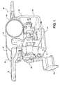
Figure 1 is a perspective view of a steering column assembly. -
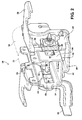
Figure 2 is a perspective view of the steering column assembly. -
Figure 3 is an exploded perspective view of the steering column assembly. -
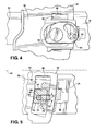
Figure 4 is a partial fragmentary side plan view of a rake cam of the steering column assembly. -
Figure 5 is a partial fragmentary side plan view of a rake lock in a locked position with a rake slot of the steering column assembly. -
Figure 6 is a partial fragmentary side plan view of the rake lock in an unlocked position with the rake slot. -
Figure 7 is a partial fragmentary side plane view of a telescope cam of the steering column assembly. -
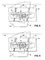
Figure 8 is a partial fragmentary side plan view of a telescope lock in a locked position with a telescope slot of the steering column assembly. -
Figure 9 is a partial fragmentary side plane view of the telescope lock in an unlocked position with the telescope slot. - Referring to the Figures, wherein like numerals indicate corresponding parts throughout the several views, a steering column assembly is shown generally at 20. The
steering column assembly 20 is for a vehicle, and is adjustable in at least one of a tilt, i.e., rake, direction and a telescopic, i.e., longitudinal direction. Thesteering column assembly 20 shown and described herein is adjustable in both the rake direction and the longitudinal direction. However, it should be appreciated that the scope of the subject invention only requires that thesteering column assembly 20 be adjustable in at least one of the rake direction and the longitudinal direction. - Referring to
Figures 1 through 3 , thesteering column assembly 20 includes acolumn jacket 22 having a steeringwheel supporting end 24 for supporting a steering wheel (not shown). Thecolumn jacket 22 extends along alongitudinal axis 26. Typically, thecolumn jacket 22 includes anupper jacket 28 and alower jacket 30. Theupper jacket 28 is telescopically engaged with and moveable relative to thelower jacket 30. The steering wheel is attached to theupper jacket 28 at the steeringwheel supporting end 24. It should be appreciated that the longitudinal adjustment of thecolumn jacket 22 adjusts the longitudinal position of the steering wheel, and is achieved through the telescopic movement between theupper jacket 28 and thelower jacket 30. - As shown, the
column jacket 22 includes acompression bracket 32. Thecompression bracket 32 is fixedly attached to thecolumn jacket 22. Thecompression bracket 32 includes afirst sidewall 34 and asecond sidewall 36 disposed on opposing sides of thecolumn jacket 22, and laterally offset from thecolumn jacket 22. Thefirst sidewall 34 and thesecond sidewall 36 are generally parallel to and spaced from each other, and extend along thelongitudinal axis 26. However, it should be appreciated that thecompression bracket 32 may be configured to include some other shape and/or configuration to meet the specific design considerations of the vehicle, and may vary from the shape and configuration shown and described herein. - A mounting
bracket 38 is coupled to thecolumn jacket 22. The mountingbracket 38 is configured for attachment to the vehicle, and interconnects thecolumn jacket 22 with the vehicle. The mountingbracket 38 may be configured to suit the specific design restraints and considerations of the vehicle, and attached to the vehicle in any suitable manner. Typically, a pair of fasteners, such as bolts, connect the mountingbracket 38 to the vehicle. However, it should be appreciated that the scope of the claims is not dependent upon the manner in which the mountingbracket 38 is configured and attached to the vehicle. - As shown, the mounting
bracket 38 includes abottom wall 40. Afirst side flange 42 and asecond side flange 44 extend generally upwardly from thebottom wall 40. Thefirst side flange 42 and thesecond side flange 44 are generally parallel to and in spaced relationship relative to each other. Thefirst side flange 42 and thesecond side flange 44 extend generally along thelongitudinal axis 26. Thefirst sidewall 34 and thesecond sidewall 36 of thecompression bracket 32 are disposed between and adjacent to thefirst side flange 42 and thesecond side flange 44 respectively, i.e., thefirst sidewall 34 is adjacent to thefirst side flange 42 and thesecond sidewall 36 is adjacent to thesecond side flange 44. - The
column jacket 22 is moveable relative to the mountingbracket 38 in at least one of a vertical direction and a longitudinal direction. Movement in the vertical direction, such as pivotal movement of thecolumn jacket 22 relative to the mountingbracket 38, adjusts a vertical position of the steeringwheel supporting end 24 of thecolumn jacket 22 and thereby the vertical position of the steering wheel. Movement in the longitudinal direction, such as through telescopic movement between theupper jacket 28 and thelower jacket 30 relative to the mountingbracket 38, adjusts a longitudinal position of the steeringwheel supporting end 24 of thecolumn jacket 22 and thereby the longitudinal position of the steering wheel. - At least one of the mounting
bracket 38 and thecolumn jacket 22 defines at least one of arake slot 46 and atelescope slot 48 respectively. The at least one of therake slot 46 and thetelescope slot 48 include a plurality ofslot teeth bracket 38 defines therake slot 46 and thecolumn jacket 22, and more specifically thecompression bracket 32, defines thetelescope slot 48. Therake slot 46 includesrake slot teeth 50 and thetelescope slot 48 includestelescope slot teeth 52. Each of thefirst sidewall 34 and thesecond sidewall 36 may define atelescope slot 48, and each of thefirst side flange 42 and thesecond side flange 44 may define arake slot 46. Accordingly, thefirst side flange 42 and thefirst sidewall 34 may define therake slot 46 and thetelescope slot 48 respectively on one side of thecolumn jacket 22, and thesecond side flange 44 and thesecond sidewall 36 define the other of therake slot 46 and thetelescope slot 48 respectively, on an opposite and opposing side of thecolumn jacket 22. - Each of the
rake slot 46 and thetelescope slot 48 include at least oneslide edge 58 having a smooth surface. Theslot teeth rake slot 46 and/or thetelescope slot 48, with theslide edge 58 being disposed on an opposite opposing edge of therespective rake slot 46 and/ortelescope slot 48. - A
lock rake slot 46 and thetelescope slot 48. Thelock lock teeth lock lock teeth slot teeth column jacket 22 relative to the mountingbracket 38. When in the unlocked position, thelock teeth slot teeth column jacket 22 relative to the mountingbracket 38. - A
shaft 60, i.e., a rake bolt, extends through the at least one of therake slot 46 and thetelescope slot 48. Theshaft 60 extends along and is rotatable about a shaft axis. The shaft axis is generally transverse or perpendicular to thelongitudinal axis 26. Theshaft 60 is coupled to and extends through thelock shaft 60 is coupled to and extends through both therake lock 62 and thetelescope lock 64. Ahandle 66 is attached to theshaft 60 for rotating theshaft 60. - Referring to
Figures 5 through 6 and8 through 9 , thelock aperture 68, with theshaft 60 extending through theaperture 68. Theshaft 60 rotatably supports thelock shaft 60. The unobstructed rotation of thelock shaft 60 permits rotation of thelock rake slot 46 and thetelescope slot 48 to align thelock teeth slot teeth lock lock teeth slot teeth lock lock teeth slot teeth - The
shaft 60 includes a cross section along thelongitudinal axis 26. The cross section of theshaft 60 includes a circular shape that defines ashaft diameter 70. Theaperture 68 includes a cross section along thelongitudinal axis 26 having a circular shape that defines anaperture diameter 72. Theaperture diameter 72 is larger than theshaft diameter 70. It should be appreciated that theaperture diameter 72 is sufficiently greater in size than theshaft diameter 70 to permit free and unrestrained rotation of thelock shaft 60. - The
lock guide surface 74. Thelock teeth lock rake slot 46 and thetelescope slot 48. Theguide surface 74 of thelock rake slot 46 and thetelescope slot 48 disposed adjacent thereto. Theguide surface 74 engages theslide edge 58 in sliding engagement when thelock guide surface 74 includes an undulating surface, such as a sinusoidal wave, that defines at least onecrest 76 and at least onevalley 78. Theguide surface 74 engages theslide edge 58 on one of the at least one crests 76 for guided pivotal rotation about one of the at least one crests 76. The undulatingguide surface 74 provides a point, i.e., one of thecrests 76, about which thelock lock teeth slot teeth - As shown and described herein, the
lock rake lock 62 disposed within therake slot 46, shown inFigures 5 and6 , and atelescope lock 64 disposed within thetelescope slot 48, shown inFigures 8 and 9 . Therake lock 62 includes rake lockteeth 54 for meshing with therake slot teeth 50. Thetelescope lock 64 includes telescope lockteeth 56 for meshing with thetelescope slot teeth 52. Preferably and as shown, therake lock 62 and thetelescope lock 64 are disposed on opposite sides of thecolumn jacket 22. However, it should be appreciated that therake lock 62 and thetelescope lock 64 may be integrally formed together, and include both therake lock teeth 54 disposed within therake slot 46, and the telescope lockteeth 56 disposed within thetelescope slot 48. - Accordingly, it should be appreciated that the
rake slot 46 having therake slot teeth 50 is disposed on one side of thecolumn jacket 22, and that thetelescope slot 48 adjacent to therake slot 46 having therake slot teeth 50 includes theslide edge 58 for which theguide surface 74 of therake lock 62 abuts. Similarly, thetelescope slot 48 having thetelescope slot teeth 52 is disposed on the opposite side of thecolumn jacket 22 from therake slot 46 having therake slot teeth 50, and that therake slot 46 adjacent to thetelescope slot 48 having thetelescope slot teeth 52 includes theslide edge 58 for which theguide surface 74 of thetelescope lock 64 abuts. - The
steering column assembly 20 includes alocking mechanism 80. Thelocking mechanism 80 is coupled to theshaft 60. Rotation of theshaft 60 actuates thelocking mechanism 80. Thelocking mechanism 80 moves therake lock 62 and thetelescope lock 64 between the respective locked positions and the unlocked positions. Thelocking mechanism 80 moves theshaft 60 within each of therake slot 46 and thetelescope slot 48 to move therake lock 62 and thetelescope lock 64 into and out of engagement with therake slot teeth 50 and thetelescope slot teeth 52. However, as described above, therake lock 62 and thetelescope lock 64 are free to rotate about theshaft 60. Therefore, as theshaft 60 is rotated to actuate thelocking mechanism 80 to move thelocks locks shaft 60. This permits thelock teeth slot teeth slot teeth - Preferably, the
locking mechanism 80 includes afirst cam mechanism 82, shown best inFigure 4 , and asecond cam mechanism 84, shown best inFigure 7 . Thefirst cam mechanism 82 moves therake lock 62. Thesecond cam mechanism 84 moves thetelescope lock 64. There are many different types and configurations of cam mechanism suitable for use with thesteering column assembly 20 of the subject invention that are capable of linearly moving theshaft 60 in response to rotation of theshaft 60. Accordingly, the scope of the claims is not limited to the exact configuration and/or type of camming mechanism shown herein. - As best shown in
Figure 3 , thesteering column assembly 20 may further include acompression camming mechanism 86. Thecompression camming mechanism 86 compresses the mountingbracket 38 against thecompression bracket 32 to create a compressive frictional force between the mountingbracket 38 and thecompression bracket 32. The compressive frictional force resists movement of thecolumn jacket 22 relative to the mountingbracket 38. More specifically, thecompression camming mechanism 86 compresses thefirst side flange 42 and thesecond side flange 44 against thefirst sidewall 34 and thesecond sidewall 36 respectively, to secure the position of thecolumn jacket 22 relative to the mountingbracket 38. There are many known types and configurations of thecompression camming mechanism 86 known that are suitable for use with thesteering column assembly 20 of the subject invention. Accordingly, it should be appreciated that the scope of the invention is not limited to the specific type, configuration and/or components of thecompression camming mechanism 86. Typically, thecompression camming mechanism 86 is coupled to and actuated by rotation of theshaft 60, and operates a cam that biases thefirst side flange 42 and thesecond side flange 44 of the mountingbracket 38 inward against ehfirst sidewall 34 and thesecond sidewall 36 of thecompression bracket 32. - The invention has been described in an illustrative manner, and it is to be understood that the terminology which has been used is intended to be in the nature of words of description rather than of limitation. As is now apparent to those skilled in the art, many modifications and variations of the present invention are possible in light of the above teachings. It is, therefore, to be understood that within the scope of the appended claims, wherein reference numerals are merely for convenience and are not to be in any way limiting, the invention may be practiced otherwise than as specifically described.
Claims (10)
- A steering column assembly (20) for a vehicle, said assembly (20) comprising:a mounting bracket (38) configured for attachment to the vehicle;a column jacket (22) coupled to said mounting bracket (38) and including a steering wheel supporting end (24) and extending along a longitudinal axis (26) and moveable relative to said mounting bracket (38) in at least one of a vertical direction and a longitudinal direction for adjusting at least one of a vertical position and a longitudinal position of said steering wheel supporting end (24);at least one of said mounting bracket (38) and said column jacket (22) defining at least one of a rake slot (46) and a telescope slot (48) respectively with said at least one of said rake slot (46) and said telescope slot (48) including a plurality of slot teeth (50, 52).a shaft (60) extending through said at least one of said rake slot (46) and said telescope slot (48) transverse to said longitudinal axis (26); anda lock (62, 64) including a plurality of lock teeth (54, 56) and disposed within said at least one of said rake slot (46) and said telescope slot (48) with said lock (62, 64) moveable between a locked position wherein said lock teeth (54, 56) are disposed in interlocking engagement with said slot teeth (50, 52) to prevent movement of said column jacket (22) relative to said mounting bracket (38) and an unlocked position wherein said lock teeth (54, 56) are disengaged from said slot teeth (50, 52) to permit movement of said column jacket (22) relative to said mounting bracket (38);said lock (62, 64) defining an aperture (68) with said shaft (60) extending through said aperture (68) and rotatably supporting said lock (62, 64) for unobstructed rotation about said shaft (60) to permit rotation of said lock (62, 64) relative to said at least one of said rake slot (46) and said telescope slot (48) to align said lock teeth (54, 56) with said slot teeth (50, 52) in full meshing engagement in response to said lock (62, 64) moving into said locked position and to limit peak-to-peak contact between said lock teeth (54, 56) and said slot teeth (50, 52).
- An assembly (20) as set forth in claim 1 wherein said shaft (60) includes a cross section along said longitudinal axis (26) having a circular shape defining a shaft diameter (70) and said aperture (68) includes a cross section along said longitudinal axis (26) having a circular shape defining an aperture diameter (72) with said aperture diameter (72) larger than said shaft diameter (70).
- An assembly (20) as set forth in any one of claims 1 and 2 wherein said mounting bracket (38) defines said rake slot (46) including rake slot teeth (50) and said column jacket (22) defines said telescope slot (48) including telescope slot teeth (52).
- An assembly (20) as set forth in any one of claims 1, 2 and 3 wherein said lock (62, 64) includes a guide surface (74) with said lock teeth (54, 56) disposed within one of said rake slot (46) and said telescope slot (48) and said guide surface (74) is disposed within another of said rake slot (46) and said telescope slot (48).
- An assembly (20) as set forth in claim 4 wherein each of said rake slot (46) and said telescope slot (48) include at least one slide edge (58) having a smooth surface and wherein said guide surface (74) includes an undulating surface defining at least one crest (76) and at least one valley (78) with said guide surface (74) engaging said slide edge (58) for guided pivotal rotation about one of said at least one crest (76).
- An assembly (20) as set forth in any one of claims 1, 2, 3, 4, 5 and 6 wherein said lock (62, 64) includes a rake lock (62) including rake lock teeth (54) for engaging said rake slot teeth (50) and further includes a telescope lock (64) including telescope lock teeth (56) for engaging said telescope slot teeth (52).
- An assembly (20) as set forth in claim 6 wherein said rake lock (62) and said telescope lock (64) are disposed on opposite sides of said column jacket (22).
- An assembly (20) as set forth in any one of claims 6 and 7 further including a locking mechanism (80) coupled to said shaft (60) for moving said rake lock (62) and said telescope lock (64) between said respective locked positions and said unlocked positions.
- An assembly (20) as set forth in claim 8 wherein said locking mechanism (80) includes a first cam mechanism (82) for moving said rake lock (62) and a second cam mechanism (84) for moving said telescope lock (64).
- An assembly (20) as set forth in any one of claims 1, 2, 3, 4, 5, 6, 7, 8 and 9 wherein said column jacket (22) includes a compression bracket (32) and wherein said assembly further comprises a compression camming mechanism (86) for compressing said mounting bracket (38) against said compression bracket (32) to create a compressive frictional force between said mounting bracket (38) and said compression bracket (32) to resist movement of said column jacket (22) relative to said mounting bracket (38).
Applications Claiming Priority (2)
| Application Number | Priority Date | Filing Date | Title |
|---|---|---|---|
| US6891408P | 2008-03-11 | 2008-03-11 | |
| US12/367,915 US8671795B2 (en) | 2008-03-11 | 2009-02-09 | Locking mechanism for an adjustable steering column having impact teeth |
Publications (3)
| Publication Number | Publication Date |
|---|---|
| EP2100795A2 true EP2100795A2 (en) | 2009-09-16 |
| EP2100795A3 EP2100795A3 (en) | 2010-03-03 |
| EP2100795B1 EP2100795B1 (en) | 2011-10-26 |
Family
ID=40751058
Family Applications (1)
| Application Number | Title | Priority Date | Filing Date |
|---|---|---|---|
| EP09154344A Expired - Fee Related EP2100795B1 (en) | 2008-03-11 | 2009-03-04 | Locking mechanism for an adjustable steering column having impact teeth |
Country Status (2)
| Country | Link |
|---|---|
| US (1) | US8671795B2 (en) |
| EP (1) | EP2100795B1 (en) |
Cited By (4)
| Publication number | Priority date | Publication date | Assignee | Title |
|---|---|---|---|---|
| CN102985308A (en) * | 2011-06-28 | 2013-03-20 | 日本精工株式会社 | Steering device |
| WO2013038079A1 (en) | 2011-09-14 | 2013-03-21 | Zf Systeme De Direction Nacam Sas | Steering column comprising an improved depth-blocking mechanism |
| WO2014108676A1 (en) * | 2013-01-08 | 2014-07-17 | Trw Limited | Clamp assembly for a steering column assembly |
| EP2796341A1 (en) * | 2013-04-24 | 2014-10-29 | Jtekt Corporation | Steering system |
Families Citing this family (24)
| Publication number | Priority date | Publication date | Assignee | Title |
|---|---|---|---|---|
| FR2915950B1 (en) * | 2007-05-11 | 2009-07-03 | Zf Systemes De Direction Nacam Sas | DEVICE FOR HOLDING IN THE ENERGY ABSORPTION POSITION OF A STEERING COLUMN OF A MOTOR VEHICLE |
| US8327733B2 (en) * | 2008-03-11 | 2012-12-11 | Steering Solutions Ip Holding Corporation | Pivoting locking device for an adjustable steering column |
| JP5328695B2 (en) * | 2010-02-26 | 2013-10-30 | 富士機工株式会社 | Steering column device |
| US8641094B2 (en) * | 2010-11-23 | 2014-02-04 | Steering Solutions Ip Holding Corporation | Steering column telescope adjustment stop |
| CN102905951B (en) * | 2011-03-31 | 2015-05-13 | 日本精工株式会社 | Steering column device |
| JP2013047060A (en) * | 2011-08-29 | 2013-03-07 | Jtekt Corp | Vehicle steering device |
| US8869645B2 (en) * | 2011-11-15 | 2014-10-28 | Steering Solutions Ip Holding Corporation | Linear travel adjustment assembly |
| US8888131B2 (en) * | 2012-06-29 | 2014-11-18 | Steering Solutions Ip Holding Corporation | Position lock for steering column |
| US9162701B2 (en) | 2013-03-13 | 2015-10-20 | Steering Solutions Ip Holding Corporation | Steering column energy absorbing rake lock |
| DE102014102661B3 (en) * | 2014-02-28 | 2015-04-02 | Thyssenkrupp Presta Ag | Steering column for a motor vehicle |
| US9764757B2 (en) * | 2014-06-27 | 2017-09-19 | Steering Solutions Ip Holding Corporation | Steering column energy absorbing rake lock |
| FR3029489B1 (en) * | 2014-12-09 | 2018-06-15 | Zf Systemes De Direction Nacam S.A.S. | ADJUSTABLE STEERING COLUMN MECHANISM IN DEPTH WITH RETRACTABLE ROD |
| KR101603020B1 (en) * | 2014-12-18 | 2016-03-21 | 주식회사 만도 | Steering Column Of Vehicle |
| US9393986B1 (en) * | 2015-01-29 | 2016-07-19 | Steering Solutions Ip Holding Corporation | Steering column clamp mechanism |
| CN107848557B (en) * | 2015-04-24 | 2020-03-13 | 罗伯特·博世汽车转向有限责任公司 | Adjustable steering column lock |
| US9849905B2 (en) * | 2016-03-09 | 2017-12-26 | Steering Solutions Ip Holding Corporation | Adjustable steering column assembly |
| JP6621359B2 (en) * | 2016-03-31 | 2019-12-18 | 富士機工株式会社 | Steering column device |
| EP3421326A4 (en) * | 2016-04-08 | 2019-04-24 | NSK Ltd. | Position adjustment device for steering wheel |
| JP6667106B2 (en) * | 2016-04-26 | 2020-03-18 | 株式会社ジェイテクト | Steering device |
| JP6742167B2 (en) * | 2016-06-21 | 2020-08-19 | 株式会社山田製作所 | Steering device |
| DE102018201029B4 (en) * | 2017-01-26 | 2024-10-31 | Hl Mando Corporation | TILT DEVICE FOR AUTOMOTIVE STEERING COLUMN |
| DE102017115276B4 (en) * | 2017-07-07 | 2025-01-09 | Zf Automotive Germany Gmbh | locking device and steering column assembly |
| US10717457B2 (en) * | 2018-06-18 | 2020-07-21 | Steering Solutions Ip Holding Corporation | Steering column positive lock mechanism |
| EP3976443B1 (en) * | 2019-05-31 | 2025-12-24 | NSK Ltd. | Steering column positive lock drive mechanism |
Citations (1)
| Publication number | Priority date | Publication date | Assignee | Title |
|---|---|---|---|---|
| GB2311839A (en) | 1996-04-02 | 1997-10-08 | Nastech Europ Ltd | A reach and rake adjustable steering column device |
Family Cites Families (15)
| Publication number | Priority date | Publication date | Assignee | Title |
|---|---|---|---|---|
| US5722299A (en) * | 1994-06-30 | 1998-03-03 | Fuji Kiko Co., Ltd. | Adjustable steering column assembly for a vehicle |
| JP3186445B2 (en) * | 1994-07-04 | 2001-07-11 | 日本精工株式会社 | Tilt type steering column device |
| US5823062A (en) * | 1996-12-12 | 1998-10-20 | Chrysler Corporation | Tilt steering column lock |
| US6139057A (en) * | 1999-02-04 | 2000-10-31 | Delphi Technologies, Inc. | Position control apparatus for steering column |
| US6419269B1 (en) * | 1999-09-20 | 2002-07-16 | Delphi Technologies | Locking system for adjustable position steering column |
| US6659504B2 (en) * | 2001-05-18 | 2003-12-09 | Delphi Technologies, Inc. | Steering column for a vehicle |
| US7331608B2 (en) * | 2002-06-27 | 2008-02-19 | Delphi Technologies, Inc. | Electrically actuated steering column mechanism |
| KR100599483B1 (en) * | 2004-11-03 | 2006-07-12 | 현대모비스 주식회사 | Pop-up protection structure of the steering column |
| US7827880B2 (en) * | 2005-03-21 | 2010-11-09 | Gm Global Technology Operations, Inc. | Steering column assembly with a quick release bolt |
| US7367589B2 (en) * | 2005-07-15 | 2008-05-06 | Chrysler Llc | Collapsible steering assembly with a stationary reaction surface |
| DE102005036582A1 (en) * | 2005-08-01 | 2007-02-08 | Thyssenkrupp Presta Ag | Adjustable steering column for a motor vehicle |
| US7574941B2 (en) * | 2007-02-20 | 2009-08-18 | Delphi Technologies, Inc. | Adjustable steering column assembly having a rake and telescope locking system |
| US7635149B2 (en) * | 2007-03-21 | 2009-12-22 | Gm Global Technology Operations, Inc. | Rocker-arm lock device of an adjustable steering column assembly |
| US7819426B2 (en) * | 2008-04-24 | 2010-10-26 | Gm Global Technology Operations, Inc. | Over-center locking mechanism for steering column assembly |
| US7685903B2 (en) * | 2008-05-19 | 2010-03-30 | Gm Global Technology Operations, Inc. | Dual on-center column lock mechanism |
-
2009
- 2009-02-09 US US12/367,915 patent/US8671795B2/en active Active
- 2009-03-04 EP EP09154344A patent/EP2100795B1/en not_active Expired - Fee Related
Patent Citations (1)
| Publication number | Priority date | Publication date | Assignee | Title |
|---|---|---|---|---|
| GB2311839A (en) | 1996-04-02 | 1997-10-08 | Nastech Europ Ltd | A reach and rake adjustable steering column device |
Cited By (8)
| Publication number | Priority date | Publication date | Assignee | Title |
|---|---|---|---|---|
| CN102985308A (en) * | 2011-06-28 | 2013-03-20 | 日本精工株式会社 | Steering device |
| CN102985308B (en) * | 2011-06-28 | 2015-07-08 | 日本精工株式会社 | Steering device |
| WO2013038079A1 (en) | 2011-09-14 | 2013-03-21 | Zf Systeme De Direction Nacam Sas | Steering column comprising an improved depth-blocking mechanism |
| US9168945B2 (en) | 2011-09-14 | 2015-10-27 | Robert Bosch Automotive Steering Vendome | Steering column comprising an improved depth-blocking mechanism |
| WO2014108676A1 (en) * | 2013-01-08 | 2014-07-17 | Trw Limited | Clamp assembly for a steering column assembly |
| US10293845B2 (en) | 2013-01-08 | 2019-05-21 | Trw Limited | Clamp assembly for a steering column assembly |
| EP2796341A1 (en) * | 2013-04-24 | 2014-10-29 | Jtekt Corporation | Steering system |
| US9073573B2 (en) | 2013-04-24 | 2015-07-07 | Jtekt Corporation | Steering system |
Also Published As
| Publication number | Publication date |
|---|---|
| US8671795B2 (en) | 2014-03-18 |
| EP2100795B1 (en) | 2011-10-26 |
| US20090229399A1 (en) | 2009-09-17 |
| EP2100795A3 (en) | 2010-03-03 |
Similar Documents
| Publication | Publication Date | Title |
|---|---|---|
| US8671795B2 (en) | Locking mechanism for an adjustable steering column having impact teeth | |
| US8327733B2 (en) | Pivoting locking device for an adjustable steering column | |
| US7685903B2 (en) | Dual on-center column lock mechanism | |
| US8783717B2 (en) | Steering column telescope lock | |
| US8438944B2 (en) | Telescope positive lock for steering column | |
| US9764757B2 (en) | Steering column energy absorbing rake lock | |
| US8881618B2 (en) | Adjustable steering column lock | |
| CN100364831C (en) | steering gear | |
| JP5230527B2 (en) | Steering column device | |
| US20050121578A1 (en) | Locking joint for support arm | |
| US7815220B2 (en) | Tilting and telescoping steering column assembly | |
| US7798037B2 (en) | Wedge arm positive rake lock | |
| EP2361816A2 (en) | Steering column device | |
| CN102523738A (en) | Steering device | |
| KR20160055862A (en) | Locking unit for a vehicle seat, and vehicle seat | |
| EP2607207A2 (en) | Steering device | |
| US11975756B2 (en) | Steering column telescope assembly and energy absorption device | |
| CN110636966B (en) | Locking device and steering column assembly | |
| JP2005138825A (en) | Steering column device | |
| US8794671B1 (en) | Anti-unlocking device for adjustable steering column | |
| US7503234B2 (en) | One lever tilt and telescope mechanism | |
| WO2015028803A1 (en) | A steering column assembly | |
| RU2734149C1 (en) | Steering shaft lock | |
| JP2008149969A (en) | Steering column device | |
| EP4017782B1 (en) | Steering column telescope positive lock and breakaway device |
Legal Events
| Date | Code | Title | Description |
|---|---|---|---|
| PUAI | Public reference made under article 153(3) epc to a published international application that has entered the european phase |
Free format text: ORIGINAL CODE: 0009012 |
|
| AK | Designated contracting states |
Kind code of ref document: A2 Designated state(s): AT BE BG CH CY CZ DE DK EE ES FI FR GB GR HR HU IE IS IT LI LT LU LV MC MK MT NL NO PL PT RO SE SI SK TR |
|
| AX | Request for extension of the european patent |
Extension state: AL BA RS |
|
| PUAL | Search report despatched |
Free format text: ORIGINAL CODE: 0009013 |
|
| AK | Designated contracting states |
Kind code of ref document: A3 Designated state(s): AT BE BG CH CY CZ DE DK EE ES FI FR GB GR HR HU IE IS IT LI LT LU LV MC MK MT NL NO PL PT RO SE SI SK TR |
|
| AX | Request for extension of the european patent |
Extension state: AL BA RS |
|
| 17P | Request for examination filed |
Effective date: 20100601 |
|
| 17Q | First examination report despatched |
Effective date: 20100702 |
|
| AKX | Designation fees paid |
Designated state(s): DE |
|
| RAP1 | Party data changed (applicant data changed or rights of an application transferred) |
Owner name: GM GLOBAL TECHNOLOGY OPERATIONS, INC. |
|
| GRAP | Despatch of communication of intention to grant a patent |
Free format text: ORIGINAL CODE: EPIDOSNIGR1 |
|
| RIC1 | Information provided on ipc code assigned before grant |
Ipc: B62D 1/184 20060101AFI20110330BHEP |
|
| RAP1 | Party data changed (applicant data changed or rights of an application transferred) |
Owner name: GM GLOBAL TECHNOLOGY OPERATIONS LLC |
|
| GRAS | Grant fee paid |
Free format text: ORIGINAL CODE: EPIDOSNIGR3 |
|
| GRAA | (expected) grant |
Free format text: ORIGINAL CODE: 0009210 |
|
| AK | Designated contracting states |
Kind code of ref document: B1 Designated state(s): DE |
|
| REG | Reference to a national code |
Ref country code: DE Ref legal event code: R096 Ref document number: 602009003244 Country of ref document: DE Effective date: 20111222 |
|
| PLBE | No opposition filed within time limit |
Free format text: ORIGINAL CODE: 0009261 |
|
| STAA | Information on the status of an ep patent application or granted ep patent |
Free format text: STATUS: NO OPPOSITION FILED WITHIN TIME LIMIT |
|
| 26N | No opposition filed |
Effective date: 20120727 |
|
| REG | Reference to a national code |
Ref country code: DE Ref legal event code: R097 Ref document number: 602009003244 Country of ref document: DE Effective date: 20120727 |
|
| REG | Reference to a national code |
Ref country code: DE Ref legal event code: R082 Ref document number: 602009003244 Country of ref document: DE Representative=s name: MANITZ, FINSTERWALD & PARTNER GBR, DE |
|
| PGFP | Annual fee paid to national office [announced via postgrant information from national office to epo] |
Ref country code: DE Payment date: 20130327 Year of fee payment: 5 |
|
| REG | Reference to a national code |
Ref country code: DE Ref legal event code: R081 Ref document number: 602009003244 Country of ref document: DE Owner name: GM GLOBAL TECHNOLOGY OPERATIONS LLC (N. D. GES, US Free format text: FORMER OWNER: GM GLOBAL TECHNOLOGY OPERATIONS LLC (N. D. GESETZEN DES STAATES DELAWARE), DETROIT, US Effective date: 20130325 Ref country code: DE Ref legal event code: R082 Ref document number: 602009003244 Country of ref document: DE Representative=s name: MANITZ, FINSTERWALD & PARTNER GBR, DE Effective date: 20130325 Ref country code: DE Ref legal event code: R081 Ref document number: 602009003244 Country of ref document: DE Owner name: STEERING SOLUTIONS IP HOLDING CORP., US Free format text: FORMER OWNER: GM GLOBAL TECHNOLOGY OPERATIONS LLC (N. D. GESETZEN DES STAATES DELAWARE), DETROIT, US Effective date: 20130325 Ref country code: DE Ref legal event code: R081 Ref document number: 602009003244 Country of ref document: DE Owner name: GM GLOBAL TECHNOLOGY OPERATIONS LLC (N. D. GES, US Free format text: FORMER OWNER: GM GLOBAL TECHNOLOGY OPERATIONS LLC (N. D. GESETZEN DES STAATES DELAWARE), DETROIT, MICH., US Effective date: 20130325 Ref country code: DE Ref legal event code: R081 Ref document number: 602009003244 Country of ref document: DE Owner name: STEERING SOLUTIONS IP HOLDING CORP., SAGINAW, US Free format text: FORMER OWNER: GM GLOBAL TECHNOLOGY OPERATIONS LLC (N. D. GESETZEN DES STAATES DELAWARE), DETROIT, MICH., US Effective date: 20130325 |
|
| REG | Reference to a national code |
Ref country code: DE Ref legal event code: R119 Ref document number: 602009003244 Country of ref document: DE |
|
| REG | Reference to a national code |
Ref country code: DE Ref legal event code: R119 Ref document number: 602009003244 Country of ref document: DE Effective date: 20141001 |
|
| PG25 | Lapsed in a contracting state [announced via postgrant information from national office to epo] |
Ref country code: DE Free format text: LAPSE BECAUSE OF NON-PAYMENT OF DUE FEES Effective date: 20141001 |