EP2100781A1 - Vehicle airbaig device and method for manufacturing the same - Google Patents
Vehicle airbaig device and method for manufacturing the same Download PDFInfo
- Publication number
- EP2100781A1 EP2100781A1 EP09154663A EP09154663A EP2100781A1 EP 2100781 A1 EP2100781 A1 EP 2100781A1 EP 09154663 A EP09154663 A EP 09154663A EP 09154663 A EP09154663 A EP 09154663A EP 2100781 A1 EP2100781 A1 EP 2100781A1
- Authority
- EP
- European Patent Office
- Prior art keywords
- opening
- base member
- tear
- airbag
- flap
- Prior art date
- Legal status (The legal status is an assumption and is not a legal conclusion. Google has not performed a legal analysis and makes no representation as to the accuracy of the status listed.)
- Granted
Links
- 238000004519 manufacturing process Methods 0.000 title claims description 18
- 238000000034 method Methods 0.000 title claims description 12
- 239000000853 adhesive Substances 0.000 claims description 28
- 230000001070 adhesive effect Effects 0.000 claims description 28
- 239000010985 leather Substances 0.000 description 45
- 239000012790 adhesive layer Substances 0.000 description 37
- 238000012986 modification Methods 0.000 description 13
- 230000004048 modification Effects 0.000 description 13
- 239000004744 fabric Substances 0.000 description 11
- 230000001788 irregular Effects 0.000 description 7
- 230000000694 effects Effects 0.000 description 5
- 230000002411 adverse Effects 0.000 description 2
- 239000000805 composite resin Substances 0.000 description 2
- 238000010586 diagram Methods 0.000 description 1
- 239000010410 layer Substances 0.000 description 1
- 239000000463 material Substances 0.000 description 1
- 239000011347 resin Substances 0.000 description 1
- 229920005989 resin Polymers 0.000 description 1
- 230000003763 resistance to breakage Effects 0.000 description 1
Images





Classifications
-
- B—PERFORMING OPERATIONS; TRANSPORTING
- B60—VEHICLES IN GENERAL
- B60R—VEHICLES, VEHICLE FITTINGS, OR VEHICLE PARTS, NOT OTHERWISE PROVIDED FOR
- B60R21/00—Arrangements or fittings on vehicles for protecting or preventing injuries to occupants or pedestrians in case of accidents or other traffic risks
- B60R21/02—Occupant safety arrangements or fittings, e.g. crash pads
- B60R21/16—Inflatable occupant restraints or confinements designed to inflate upon impact or impending impact, e.g. air bags
- B60R21/20—Arrangements for storing inflatable members in their non-use or deflated condition; Arrangement or mounting of air bag modules or components
- B60R21/215—Arrangements for storing inflatable members in their non-use or deflated condition; Arrangement or mounting of air bag modules or components characterised by the covers for the inflatable member
- B60R21/2165—Arrangements for storing inflatable members in their non-use or deflated condition; Arrangement or mounting of air bag modules or components characterised by the covers for the inflatable member characterised by a tear line for defining a deployment opening
-
- B—PERFORMING OPERATIONS; TRANSPORTING
- B60—VEHICLES IN GENERAL
- B60R—VEHICLES, VEHICLE FITTINGS, OR VEHICLE PARTS, NOT OTHERWISE PROVIDED FOR
- B60R21/00—Arrangements or fittings on vehicles for protecting or preventing injuries to occupants or pedestrians in case of accidents or other traffic risks
- B60R21/02—Occupant safety arrangements or fittings, e.g. crash pads
- B60R21/16—Inflatable occupant restraints or confinements designed to inflate upon impact or impending impact, e.g. air bags
- B60R21/20—Arrangements for storing inflatable members in their non-use or deflated condition; Arrangement or mounting of air bag modules or components
- B60R21/215—Arrangements for storing inflatable members in their non-use or deflated condition; Arrangement or mounting of air bag modules or components characterised by the covers for the inflatable member
- B60R2021/21531—Arrangements for storing inflatable members in their non-use or deflated condition; Arrangement or mounting of air bag modules or components characterised by the covers for the inflatable member using a strechable wall liner
-
- Y—GENERAL TAGGING OF NEW TECHNOLOGICAL DEVELOPMENTS; GENERAL TAGGING OF CROSS-SECTIONAL TECHNOLOGIES SPANNING OVER SEVERAL SECTIONS OF THE IPC; TECHNICAL SUBJECTS COVERED BY FORMER USPC CROSS-REFERENCE ART COLLECTIONS [XRACs] AND DIGESTS
- Y10—TECHNICAL SUBJECTS COVERED BY FORMER USPC
- Y10T—TECHNICAL SUBJECTS COVERED BY FORMER US CLASSIFICATION
- Y10T156/00—Adhesive bonding and miscellaneous chemical manufacture
- Y10T156/10—Methods of surface bonding and/or assembly therefor
Definitions
- the present invention relates to a vehicle airbag device and to a method for manufacturing the same.
- An airbag device is disclosed in Japanese Patent Application Laid-Open Publication No. 2004-276680 ( JP 2004-276680 A ), which airbag device is provided with an airbag and a leather-upholstered airbag cover in which leather is used, the airbag cover being provided in such a manner as to cover the folded airbag.
- the leather-upholstered airbag cover is formed by applying leather to a resin cover body.
- a weakened part having reduced tensile strength is formed on the back surface of the leather.
- the weakened part is comprised of numerous incisions. The weakened part causes the leather to smoothly break when the cover body is ruptured.
- the thickness of the leather must be 0.6 mm, and the incisions must be provided at a pitch of 4 mm in order to form the weakened part, and there is a risk of increased resistance to breakage of the weakened part when the parameters of 0.6 mm and 4 mm are exceeded.
- An object of the present invention is to provide a vehicle airbag device for imparting anisotropy to the opening resistance that acts on a first flap on one side of a lid part and a second flap on the other side of the lid part, and restricting the deployment direction of the airbag.
- a vehicle airbag device comprising: a base member having an airbag deployment opening and at least one flap being capable of opening the opening by pivoting about a hinge shaft provided at an edge of the opening; a skin member layered on the base member; a tear seam for breaking in correspondence with the flap by deployment of the airbag, the tear seam being formed in the skin member so as to extend toward an axis line of the hinge shaft in a region further to outside than the opening; and detaching parts formed so as to correspond to the tear seam and so as to be detached from the base member by the flap at which the skin member opens in the outside region of the opening.
- the tear seam can impart anisotropy to the necessary load for opening the skin member, and the deployment direction of the flap and the airbag can be adjusted.
- the flap comprises two sections, a pair of hinge shafts corresponding to each of the flaps is provided opposite each other at edges of the opening, and the tear seam is formed so as to extend toward the axis line of one hinge shaft of the pair of hinge shafts and away from the other hinge shaft. Consequently, the coming apart of the flaps is accompanied by smooth breakage of the tear seam.
- one flap of the two flaps is formed as an outward-curving door in which the width from both ends of a free end of the flap to the hinge shaft is minimized; and the other flap of the two flaps is formed as an inward-curving door having a shape in which a free end of the flap matches the free end of the one flap. Consequently, the two flaps fit together in a curve, and the flaps therefore come apart smoothly.
- the flaps are demarcated by a weakened part that is broken by deployment of the airbag, the weakened part being formed in the base member, and the tear part is provided along the weakened part.
- interference between the flaps and the broken tear part can be reduced by causing the weakened part and the tear part to substantially coincide with each other.
- the other hinge shaft is provided in a lower position than the one hinge shaft, and the opening is provided at an angle. Consequently, the tear seam reduces interference between the airbag and the one flap that opens widely, and the one flap and the other flap can guide the airbag so as to deploy toward the hinge shaft of the one flap. For example, when the opening or the one flap is tilted toward the inside of the passenger compartment, the airbag deploys toward the inside of the passenger compartment.
- the region further to the outside than the opening includes an adhesion-adjusted part that is adjusted so that the adhesion between the base member and the skin member is reduced. Opening of the flaps is facilitated by the detaching of the adhesion-adjusted part from the base member. Consequently, linear opening is obtained, the flaps can be stably opened, and adverse effects on the external appearance can be reduced by causing the skin on the surface of the flaps to detach without using special processing or significantly breaking the skin member.
- the adhesion-adjusted part is adjusted so that the surface area in which an adhesive is applied between the base member and the skin member is smaller than the surface area on which an adhesive is applied in the other outside region. Consequently, the skin member in the region further to the outside than the opening easily detaches, and the resistance to detachment of the skin member from the base member can be reduced. As a result, the opening resistance during opening of the leather by the airbag deployment can be reduced, and the airbag can deploy satisfactorily.
- the adhesion-adjusted part is adjusted by forming a patterned indented part in the base member so that the surface area of contact between the base member and the skin member is smaller than the surface area of contact of the other outside region.
- the skin member therefore easily detaches from the base member.
- a method for manufacturing a vehicle airbag device comprising the steps of: obtaining a base member having an airbag deployment opening and flaps provided at the opening in such a manner as to be capable of opening; layering on the base member a skin member having a stitch-formed tear part for breaking together with the flaps by deployment of the airbag; forming a tear seam by arranging the tear part to essentially coincide with free ends of the flaps and to extend to continue to a region outside the flaps; and bonding the skin member to the base member in a state in which an adhesion-adjusted part in which the adhesion is reduced to correspond to the tear seam is provided outside the opening.
- the operation of positioning the skin member relative to the flaps can be combined with bonding the skin member to the base member.
- the manufacturing method further comprises a step of placing together and positioning a holder formed in the skin member so as to accommodate the tear part, and a protrusion formed in the base member so as to engage with the holder.
- the skin member can thus be easily positioned with respect to the base member.
- the manufacturing method further comprises a step of forming a weakened part on a back surface of the base member on which the protrusion is formed, the weakened part being formed along the protrusion.
- the difference in the strength of the protrusion and the strength of the weakened part enables the flaps to reliably break from the weakened part, and the tear part to open at substantially the same time.
- the skin member comprises a surface member to which the tear part is provided, and a middle member layered with the surface member and provided with the holder in which the tear part is accommodated; and the manufacturing method further comprises a step of placing the tear part of the surface member inside the holder.
- the precision of the skin member positioning with respect to the flaps, and the breaking strength of the surface member can thus be set so as to depend on the middle member and the surface member, and the degree of freedom of design is enhanced.
- the airbag device 11 is used at the front passenger seat 13 of a vehicle 12.
- the vehicle 12 is provided with a vehicle body 21, a passenger compartment 22, a driver seat 23, a front passenger seat 13, a windshield 24, an instrument panel 25, and an airbag unit 27 that includes the airbag device 11 for the front passenger seat 13 and an airbag device 26 for the driver seat 23.
- a top part 31 on the side where the front passenger seat 13 is located curves outward in the shape of a gentle sphere with a large radius, and leather 32 is applied to the instrument panel 25.
- the airbag device 11 has an enclosure 36 that is provided in an opening 35 formed in an instrument panel main body (base member) 34 of the instrument panel 25; an airbag 38 accommodated within the enclosure 36; an inflator 37 for deploying the airbag 38; an openable lid part 41 provided at the top of the enclosure 36; a skin member 43 applied to the base member 34 of the lid part 41 and the instrument panel 25; outside regions 44 positioned further to the outside than the opening 35 of the base member 34; and adhesion-adjusted parts 45 formed in the outside regions 44.
- the lid part 41 is comprised of a first flap (one flap) 51 that is formed in the enclosure 36 via a first hinge 47; a second flap (other flap) 53 that is formed in the enclosure 36 via a second hinge 52; and a tear line 55 for demarcating the first flap 51 and the second flap 53.
- the second hinge 52 and the second flap 53 are positioned toward the windshield 24, and the first hinge 47 and the first flap 51 are positioned toward the rear of the vehicle 12 (in the direction of the arrow a1).
- the first hinge 47 has a first hinge shaft 56.
- the second hinge 52 has a second hinge shaft 57.
- the first hinge shaft 56 is positioned at a distance h lower than the second hinge shaft 57, and the opening 35 is provided at an angle (average tilt angle ⁇ ).
- first hinge shaft 56 refers to a part that is formed at the smallest thickness of the first hinge 47, and acts as the supporting point of the hinge. The same applies for the second hinge shaft 57.
- the tear line 55 has a central tear line 58 that is a weakened part cut as a V-shaped groove in the back of the lid part 41.
- the central tear line 58 is offset an average distance E from the center (W ⁇ 50%) of the width W of the lid part 41, and has a curved shape in which the center of the curve is set towards the first hinge 47.
- the lid part 41 is divided into the first flap 51 and the second flap 53 by the breaking of the central tear line 58, and forms a first free end 61 (see also FIG. 6 ) of the first flap 51, and a second free end 62 (see also FIG. 6 ) of the second flap 53.
- the reference numeral 64 refers to a first side tear line
- the reference numeral 65 refers to a second side tear line.
- a plurality of retaining protrusions 66 for engaging with the instrument panel 25 is formed in the enclosure 36.
- the first flap 51 is formed as an outward-curving door in which the width W1 from both ends (both end corners) 67 of the first free end 61 to the first hinge shaft 56 is minimized.
- the second flap 53 is formed as an inward-curving door provided with the second free end 62 that matches the first free end 61.
- the skin member 43 is applied to the outward-curving door (first flap) 51 and the inward-curving door 53 to enhance the design.
- the skin member 43 is comprised of a middle member (space fabric) 72 bonded on the lid part 41 by a skin member adhesive layer 71, and leather 32 bonded on the space fabric 72 by a leather adhesive layer 73.
- the space fabric 72 is a cloth or a cloth-resin composite, and a stitch holder 76 is formed therein so that a stitched part 75 of the leather 32 can be accommodated.
- the stitched part 75 is positioned so as to be disposed at a predetermined distance from the stitch holder 76 when the stitched part 75 is accommodated, and a gap is formed between the stitched part 75 and the stitch holder 76. A misalignment with respect to the space fabric 72 and the base member 34 is thereby allowed.
- the stitch holder 76 is provided in proximity to and along the central tear line 58 on the back of the lid part 41, and is provided on the surface of the lid part 41 and the surface of the base member 34.
- the leather 32 is artificial or natural leather
- the stitched part 75 is formed therein by stitching second leather 78 to first leather 77
- stitches 81 are provided close together along the stitched part 75
- the stitched part 75 is provided along the central tear line 58 on the back of the lid part 41, and above the central tear line 58.
- the stitched part 75 also acts as a tear part, and the tear part (stitched part) 75 is provided with a lid upper tear part 83 positioned at the top of the lid part 41, and a tear seam 84 that connects to the lid top tear part 83.
- the stitched part 75 is provided with the tear seam 84 that is formed so as to extend toward the axis line C 1 (in the direction of the arrow a2) of the first hinge shaft 56, in the outside regions 44 that extend to the lid upper tear part 83 positioned at the top of the lid part 41.
- the lid upper tear part 83 is provided along the weakened part (central tear line) 58.
- the stitched part 75 is formed in a curved shape, and the center of the curve is set toward the first hinge 47.
- a skin opening 91 is formed by the breakage of thread 86 of the stitched part 75 that is positioned at the top of the lid part 41, and the leather 32 has a first skin detaching part 93 that is connected to one side of the skin opening 91 and that detaches to a predetermined distance Ls, and a second skin detaching part 94 that is connected to the other side of the skin opening 91 and that detaches to a predetermined distance Ls.
- the “detaching of the skin member 43" refers to the two layers that include the leather 32 and the space fabric 72 detaching as a body from the base member 34.
- the distances Ls shown in FIG. 2 are also the lengths of the adhesion-adjusted parts 45, and are set to approximately 1.6 times the width W of the lid part 41.
- the adhesion-adjusted parts 45 are formed to the outside (in the direction of the arrow a3) of one end (the first side tear line 64) of the lid part 41, and to the outside (in the direction of the arrow a4) of the other end (the second side tear line 65) of the lid part 41.
- the adhesion-adjusted parts 45 are provided within triangular regions formed by line segments that pass through first endpoints 95, second endpoints 96, and third endpoints 97 in plan view, and weak adhesive layers 101 are formed in the triangular regions.
- the first endpoints 95 are endpoints intersected by lines S1 that are positioned at a distance E2 to the outside of the opening 35 (in the direction of the arrow a1) from the axis line C1 of the first hinge shaft 56.
- the second endpoints 96 are endpoints that are positioned at a distance L1 to the outside (in the direction of the arrow a5) from the second hinge 52.
- the third endpoints 97 are endpoints that are positioned at a distance E2 to the outside of the opening 35 (in the direction of the arrow a1) from the axis line C1 of the first hinge shaft 56.
- the same adhesive as in the skin member adhesive layer 71 is used in these triangular regions, but the weak adhesive layers 101 are formed with the adhesive applied in a different manner.
- the weak adhesive layers 101 are formed by arranging an adhesive in substantially parallel columns at a pitch P and width Ws on both ends (first side tear line 64) of the lid part 41, and since the surface area in which the adhesive is applied is reduced in comparison to that of the other adhesion region (skin member adhesive layer 71), the adhesion force per unit of surface area is small in comparison to the skin member adhesive layer 71.
- the length of the columns is within the aforementioned triangular regions, and the ends of the columns reach S1 and S2.
- the "other adhesion region” is the portion bonded by the skin member adhesive layer 71 outside the triangular regions.
- the pitch P and width Ws are approximations, and are within desired ranges (tolerances).
- the inflator 37 when an impact occurs at the front surface of the vehicle, the inflator 37 is activated based on front-surface impact information.
- the stress on the center 103 of the central tear line 58 is increased by the deployment force of the airbag 38, and the center 103 therefore begins to break at a starting point.
- the skin opening 91 begins to open.
- the stress increases at the center 104 of the stitched part 75, i.e., at the center 104 of the lid upper tear part 83, and breakage begins with the center 104 as the starting point.
- breakage can thus be reliably initiated from the center 103 of the central tear line 58 and the center 104 of the stitched part 75, and breakage begins and progresses smoothly.
- the skin member 43 begins to detach from the base member 34 provided with the adhesion-adjusted parts 45, and the threads of the stitched part 75 break in the first skin detaching part 93 and second skin detaching part 94, the first skin detaching part 93 and the second skin detaching part 94 begin to open as indicated by the arrows a6 and a7. In other words, detachment of the skin member 43 occurs in the adhesion-adjusted parts 45.
- the adhesion force is small, and the resistance to detachment/opening of the skin member 43 can be reduced. Consequently, the resistance when the first flap 51 opens is small, and the deployment direction of the airbag 38 can be restricted.
- first flap 51 and the inward-curving door second flap 53 pivot as indicated by the arrows a6 and a7 about the supporting axes of the first hinge 47 and the second hinge 52, respectively.
- the first flap 51 can open wide, and the deployment direction of the airbag (bag) 38 can be restricted to the opening direction (direction of the arrow a6) of the first flap 51.
- FIG. 7 is a flow diagram showing an overview of the method for manufacturing the airbag device.
- Step (hereinafter abbreviated as "ST") 01 The base member 34 is resin-molded.
- ST02 The surface member (leather) 32 is fabricated.
- the skin member 43 is fabricated by bonding the surface member (leather) 32 and the middle member 72.
- FIGS. 8A and 8B show the base member and surface member obtained by the airbag device manufacturing method. The description will also refer to FIGS. 1 through 6 .
- the base member 34 is first resin-molded, as shown in FIG. 8A .
- the airbag deployment opening 35, the lid part 41, the tear line 55, and a protrusion 121 are formed in the base member 34.
- the leather 32 as the surface member is prepared as shown in FIG. 8B .
- the leather is cut into the predetermined shapes of the first leather 77 and the second leather 78.
- FIGS. 9A and 9B show the surface member fabrication step (which includes a tear part positioning step).
- the leather 32 is stitched as shown in FIG. 9A .
- the tear part 75 is formed by stitching the first leather 77 and the second leather 78 with thread 86. Stitches 81 are also provided.
- the middle member 72 is then fabricated.
- the middle member 72 comprised of a fabric material is cut along the base member 34, and the stitch holder 76 is formed.
- the skin member fabrication step is started.
- the tear part positioning step is performed first.
- the leather adhesive layer 73 is formed by applying adhesive to the middle member 72, and the leather 32 is placed on the leather adhesive layer 73.
- the tear part 75 that is the stitched part is fitted into the stitch holder 76 of the middle member 72 as indicated by the arrow b1.
- the tear part 75 is fitted into the stitch holder 76, the tear part 75 is positioned in the middle member 72.
- the tear part positioning step it is sufficient merely to fit the tear part 75 into the stitch holder 76 as indicated by the arrow b1, and positioning of the leather 32 when the skin member 43 is formed is thus facilitated.
- FIGS. 10A and 10B show the skin member adhesion step.
- the skin member adhesive layer 71 is first formed by applying adhesive to the base member 34, and the skin member 43 is placed on the skin member adhesive layer 71 as shown in FIG. 10A .
- the stitch holder 76 provided integrally with the skin member 43 is fitted on the protrusion 121 of the base member 34 as indicated by the arrow b2.
- the skin member 43 is positioned on the base member 34 when the components are fit together. Specifically, fluctuation can be reduced in the distance J from the central tear line 58 that is the weakened part to the tear part 75. In other words, the tear part 75 is easily provided and affixed along the central tear line 58 while the distance J is maintained.
- the stitch holder 76 need only be fitted over the protrusion 121, as indicated by arrow b2, and the tear part 75 of the skin member 43 is easily positioned with respect to the lid part 41 (central tear line 58).
- FIG. 11 shows the airbag device 11B according to a first modification.
- the same reference numerals are used to refer to members that are the same as those of the first embodiment.
- the airbag device 11B of the first modification differs with respect to the configuration of the adhesion-adjusted parts 45 described in the first embodiment.
- Weak adhesive layers 101B are formed in the triangular regions in the adhesion-adjusted parts 45B of the first modification.
- An adhesive is arranged in numerous points at a pitch P in the weak adhesive layers 101B.
- the weak adhesive layers 101B are arranged in points, the same operation and effects are obtained as in the airbag device 11 of the first embodiment. In other words, the deployment direction of the airbag 38 shown in FIG. 3 can be restricted.
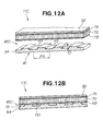
- FIGS. 12A and 12B show the airbag device 11C of a second modification that is provided with adhesion-adjusted parts 45C that differ from the adhesion-adjusted parts 45 of the first embodiment.
- the adhesion-adjusted parts 45C of the second modification are comprised of patterned irregular parts 111 that are formed on the surface of the base member 34 in the triangular regions.
- An adhesive layer 112 is formed in the same manner as the skin member adhesive layer 71 (see FIG. 4 ) of the first embodiment.
- the patterned irregular parts 111 are grooves 113 formed in straight lines substantially parallel to each other at a pitch P3 and depth D at both ends of the lid part 41, the lengths thereof are within the triangular regions, the same as in the first embodiment, and the ends thereof reach the line segments S1 and S2 shown in FIG. 2 .
- the airbag device 11C of the second modification has the same operation and effects as the airbag device 11 of the first embodiment. In other words, the deployment direction of the airbag 38 can be restricted.
- the same adhesive layer 112 as that of the skin member adhesive layer 71 of the first embodiment is thus formed on the entire surface of the middle member 72 in the second modification, the adhesive layer 112 can be affixed over the patterned irregular parts 111, and the adhesion operation is easier than in the first embodiment.
- FIGS. 13 through 18 show the airbag device 211 according to a second embodiment.
- the vehicle 212 is provided with a vehicle body 221, a passenger compartment 222, a driver seat 223, a front passenger seat 213, a windshield 224, an instrument panel 225, and an airbag unit 227 that includes the airbag device 211 for the front passenger seat 213 and an airbag device 226 for the driver seat 223.
- the airbag device 211 is provided with an enclosure 236 that is provided in an opening 235 formed in an instrument panel main body (base member) 234 of the instrument panel 225; an airbag 238 accommodated within the enclosure 236; an inflator 237 for deploying the airbag 238; an openable lid part 241 provided at the top of the enclosure 236; a skin member 243 applied to the base member 234 of the lid part 241 and the instrument panel 225; and adhesion-adjusted parts 245 formed in outside regions 244 positioned further to the outside than the opening 235 of the base member 234
- the lid part 241 is comprised of a first flap (one flap) 251 that is formed in the enclosure 236 via a first hinge 247; a second flap (other flap) 253 that is formed in the enclosure 236 via a second hinge 252; and a tear line 255 that is cut in a V shape in the back surface of the first flap 251 and the second flap 253.
- the tear line 255 is formed in the center (W ⁇ 50%) of the width W of the lid part 241, and is comprised of a central tear line 258 in a straight line that divides the first flap 251 and the second flap 253; a first side tear line 264 formed at one end in the longitudinal direction of the lid part 241, the lid part 241 having a total length L; and a second side tear line 265 formed at the other end.
- a first free end 261 (see FIG. 18 ) of the first flap 251, and a second free end 262 (see FIG. 18 ) of the second flap 253 are formed by the breaking of the central tear line 258.
- Retaining protrusions 266 for engaging with the instrument panel 225 is formed in the enclosure 236.
- the skin member 243 is comprised of a middle member (space fabric) 272 bonded on the lid part 241 by a skin member adhesive layer 271, and leather 232 bonded on the space fabric 272 by a leather adhesive layer 273.
- the space fabric 272 is a cloth or a cloth-resin composite, for example.
- a stitch-accommodating space 274 is formed so as to substantially coincide with the central tear line 258 in order to accommodate a stitched part (tear part) 275 of the leather 232.
- the leather 232 is artificial or natural leather, and the stitched part 275 is formed therein by stitching first leather 277 and second leather 278. Stitches 281 are provided close to the tear part 275 along both sides of the tear part 275.
- the tear part 275 is positioned above the central tear line 258 so as to correspond to the position of the central tear line 258 formed on the back surface of the lid part 241.
- a skin opening 291 is formed by the breakage of thread 286 of the stitched part (tear part) 275.
- a first skin detaching part 293 of the tear part 275 extends in the skin opening 291 a predetermined distance Ln from one endpoint (third endpoint) 297 of the lid part 241
- a second skin detaching part 294 of the tear part 275 extends in the skin opening 291 a predetermined distance Ln from the other endpoint (third endpoint) of the lid part 241.
- the distances Ln shown in FIG. 14 are also the lengths of the adhesion-adjusted parts 245, and are set to approximately 1.2 times the width W of the lid part 241.
- the adhesion-adjusted parts 245 are formed to the outside (in the direction of the arrow c1) of one end of the lid part 241, and to the outside (in the direction of the arrow c2) of the other end of the lid part 241, and are substantially symmetrical about the symmetry line M.
- the adhesion-adjusted parts 245 are provided within triangular regions formed by line segments that pass through first endpoints 295, second endpoints 296, and third endpoints 297 in plan view, and weak adhesive layers 301 are formed in the triangular regions.
- the first endpoints 295 are points at a distance Ln to the outside (in the direction of the arrow c1) from the first side tear line 264 of the lid part 241.
- the second endpoints 296 are a point at a distance L2 to the outside (in the direction of the arrow c3) from the first hinge 247, and a point at a distance L2 to the outside (in the direction of the arrow c4) from the second hinge 252.
- the third endpoints 297 are positioned at both corners of the first free end 261 or the second free end 262.
- the same adhesive as in the skin member adhesive layer 271 ( FIG. 16 ) is used in these triangular regions, but the weak adhesive layers 301 are formed with the adhesive applied in a different manner.
- Le is the length obtained by adding the total length L of the lid part 241, the length Ln of the first skin detaching part 293, and the length Ln of the second skin detaching part 294.
- Le is the length between the first endpoints 295, 295 of the adhesion-adjusted parts 245.
- the length Lm ( FIG. 1 ) of the stitched part 275 is greater than the length Le of the skin opening 291 (Lm > Le), and is the length from the vehicle-width center 224a of the instrument panel 225 to the left end 224b.
- the weak adhesive layers 301 are formed by arranging an adhesive in substantially parallel columns at a pitch P and width Ws at the first and second side tear lines 264, 265 on both ends of the lid part 241. Since the surface area in which the adhesive is applied is reduced in comparison to that of the other adhesion region (skin member adhesive layer 271), the adhesion force is small in comparison to the skin member adhesive layer 271.
- the lengths of the columns of adhesive in the weak adhesive layers 301 are between the line segments S 1 and S2 that form the triangular regions.
- the airbag device 211 is first fitted into the opening 235 formed in the base member 234, while the base member 234 is supported in a fixture.
- the skin member adhesive layer 271 is then formed by applying adhesive to the entire surface of the base member 234 except for the adhesion-adjusted parts 245.
- An application tool to which an adhesive is applied is then placed in the triangular regions of the base member 234 in which the adhesion-adjusted parts 245 are formed, and aligned weak adhesive layers 301 are formed by removing the application tool.
- the middle member 272 is applied to the base member 234 to which adhesive has been applied. At this time, the edges 279, 279 of the middle member 272 are separated to form a groove so that the stitch-accommodating space 274 is formed in a position corresponding to the central tear line 258 of the base member 234.
- Pre-stitched leather 232 is then applied to the middle member 272. Specifically, the adhesive is applied to the entire surface of the middle member 272, and the leather adhesive layer 273 is formed. The stitched part 275 is then positioned inside the stitch-accommodating space 274, and the leather 232 is applied to the middle member 272.
- the inflator 237 when an impact occurs at the front surface of the vehicle, the inflator 237 is activated based on front-surface impact information.
- Deployment of the airbag 238 is begun by the operation of the inflator 237. Deployment of the airbag 238 causes the central tear line 258 to break, and tearing progresses to both ends (the third endpoints 297, 297 in FIG. 14 ) of the central tear line 258. At substantially the same time, the threads 286 of the stitched part 275 that are positioned at the skin opening 291 also break, and the skin opening 291 begins to open.
- the central tear line 258 When tearing has progressed to both ends of the central tear line 258, the central tear line 258 is separated by the force of the airbag 238 deploying, and the first and second side tear lines 264, 265 begin to break.
- the first and second skin detaching parts 293, 294 begin to open as indicated by the arrow c6 ( FIG. 18 ).
- the adhesion force is small, and the resistance to detachment/opening of the skin member 243 is reduced. Consequently, adverse effects on the deploying properties of the airbag 238 can be reduced.
- first and second side tear lines 264, 265 are broken by the deploying force of the airbag 238, the first and second flaps 251, 253 pivot as indicated by the arrow c6 about the supporting axes of the first and second hinges 247, 252, respectively.
- FIG. 19 shows the airbag device 211B according to a modification of the airbag device 211 of the second embodiment.
- weak adhesive layers 301B are formed in the triangular regions, and the adhesive is arranged in numerous points at a pitch P1.
- the adhesive in the weak adhesive layers 301B is arranged in points, the same operation and effects are obtained as in the airbag device 211 of the second embodiment. In other words, the deployment direction of the airbag 238 shown in FIG. 15 can be restricted.
- patterned irregular parts are formed on the surface of the base member 234 in the triangular regions, and the patterned irregular parts may be used as adhesion-adjusted parts for application thereon via an adhesive layer, the same as in the second modification of the first embodiment.
- the length of the patterned irregular parts may also be divided to give a predetermined pitch.
- the airbag device of the present invention was adapted in the embodiments to leather used on an instrument panel, but the present invention may also be used in a location other than the instrument panel that is covered by leather.
- the adhesive of the adhesion-adjusted parts is arranged in substantially parallel lines with respect to both ends of the lid part, but the adhesive may also be arranged at a 90° angle so as to be substantially parallel to the longitudinal axis of the lid part, or the adhesive may be arranged at a 45° angle.
- An airbag device wherein a lid part (41) over an opening (35) formed in a base member (34) opens in a suitable opening direction when the airbag is deployed.
- a tear seam (84) is formed so as to extend along the axis line of a hinge shaft (57) of the lid part in a region (44) further to the outside than the opening.
- Detaching parts (93, 94) where a skin member (43) on the base member detaches from the base member are provided to the outside region.
Landscapes
- Engineering & Computer Science (AREA)
- Mechanical Engineering (AREA)
- Air Bags (AREA)
Abstract
Description
- The present invention relates to a vehicle airbag device and to a method for manufacturing the same.
- An airbag device is disclosed in Japanese Patent Application Laid-Open Publication No.
2004-276680 JP 2004-276680 A - However, it is a complex matter to manage leathers having different thicknesses, strengths, and other characteristics in order to enhance the ability of the airbag cover to deploy in the leather-upholstered airbag cover described above. In other words, the thickness of the leather must be 0.6 mm, and the incisions must be provided at a pitch of 4 mm in order to form the weakened part, and there is a risk of increased resistance to breakage of the weakened part when the parameters of 0.6 mm and 4 mm are exceeded.
- An object of the present invention is to provide a vehicle airbag device for imparting anisotropy to the opening resistance that acts on a first flap on one side of a lid part and a second flap on the other side of the lid part, and restricting the deployment direction of the airbag.
- In one aspect of the present invention, there is provided a vehicle airbag device comprising: a base member having an airbag deployment opening and at least one flap being capable of opening the opening by pivoting about a hinge shaft provided at an edge of the opening; a skin member layered on the base member; a tear seam for breaking in correspondence with the flap by deployment of the airbag, the tear seam being formed in the skin member so as to extend toward an axis line of the hinge shaft in a region further to outside than the opening; and detaching parts formed so as to correspond to the tear seam and so as to be detached from the base member by the flap at which the skin member opens in the outside region of the opening.
- With this arrangement, the tear seam can impart anisotropy to the necessary load for opening the skin member, and the deployment direction of the flap and the airbag can be adjusted.
- Preferably, the flap comprises two sections, a pair of hinge shafts corresponding to each of the flaps is provided opposite each other at edges of the opening, and the tear seam is formed so as to extend toward the axis line of one hinge shaft of the pair of hinge shafts and away from the other hinge shaft. Consequently, the coming apart of the flaps is accompanied by smooth breakage of the tear seam.
- Desirably, one flap of the two flaps is formed as an outward-curving door in which the width from both ends of a free end of the flap to the hinge shaft is minimized; and the other flap of the two flaps is formed as an inward-curving door having a shape in which a free end of the flap matches the free end of the one flap. Consequently, the two flaps fit together in a curve, and the flaps therefore come apart smoothly.
- In a preferred form, the flaps are demarcated by a weakened part that is broken by deployment of the airbag, the weakened part being formed in the base member, and the tear part is provided along the weakened part. In other words, interference between the flaps and the broken tear part can be reduced by causing the weakened part and the tear part to substantially coincide with each other.
- Preferably, the other hinge shaft is provided in a lower position than the one hinge shaft, and the opening is provided at an angle. Consequently, the tear seam reduces interference between the airbag and the one flap that opens widely, and the one flap and the other flap can guide the airbag so as to deploy toward the hinge shaft of the one flap. For example, when the opening or the one flap is tilted toward the inside of the passenger compartment, the airbag deploys toward the inside of the passenger compartment.
- Desirably, the region further to the outside than the opening includes an adhesion-adjusted part that is adjusted so that the adhesion between the base member and the skin member is reduced. Opening of the flaps is facilitated by the detaching of the adhesion-adjusted part from the base member. Consequently, linear opening is obtained, the flaps can be stably opened, and adverse effects on the external appearance can be reduced by causing the skin on the surface of the flaps to detach without using special processing or significantly breaking the skin member.
- Preferably, the adhesion-adjusted part is adjusted so that the surface area in which an adhesive is applied between the base member and the skin member is smaller than the surface area on which an adhesive is applied in the other outside region. Consequently, the skin member in the region further to the outside than the opening easily detaches, and the resistance to detachment of the skin member from the base member can be reduced. As a result, the opening resistance during opening of the leather by the airbag deployment can be reduced, and the airbag can deploy satisfactorily.
- Desirably, the adhesion-adjusted part is adjusted by forming a patterned indented part in the base member so that the surface area of contact between the base member and the skin member is smaller than the surface area of contact of the other outside region. The skin member therefore easily detaches from the base member.
- In another aspect of the present invention, there is provided a method for manufacturing a vehicle airbag device, comprising the steps of: obtaining a base member having an airbag deployment opening and flaps provided at the opening in such a manner as to be capable of opening; layering on the base member a skin member having a stitch-formed tear part for breaking together with the flaps by deployment of the airbag; forming a tear seam by arranging the tear part to essentially coincide with free ends of the flaps and to extend to continue to a region outside the flaps; and bonding the skin member to the base member in a state in which an adhesion-adjusted part in which the adhesion is reduced to correspond to the tear seam is provided outside the opening.
- Consequently, the operation of positioning the skin member relative to the flaps can be combined with bonding the skin member to the base member.
- Preferably, the manufacturing method further comprises a step of placing together and positioning a holder formed in the skin member so as to accommodate the tear part, and a protrusion formed in the base member so as to engage with the holder. The skin member can thus be easily positioned with respect to the base member.
- Desirably, the manufacturing method further comprises a step of forming a weakened part on a back surface of the base member on which the protrusion is formed, the weakened part being formed along the protrusion. The difference in the strength of the protrusion and the strength of the weakened part enables the flaps to reliably break from the weakened part, and the tear part to open at substantially the same time.
- In a preferred form, the skin member comprises a surface member to which the tear part is provided, and a middle member layered with the surface member and provided with the holder in which the tear part is accommodated; and the manufacturing method further comprises a step of placing the tear part of the surface member inside the holder. The precision of the skin member positioning with respect to the flaps, and the breaking strength of the surface member can thus be set so as to depend on the middle member and the surface member, and the degree of freedom of design is enhanced.
- Certain preferred embodiments of the present invention will be described in detail below, by way of example only, with reference to the accompanying drawings, in which:
-
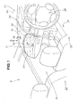
FIG. 1 is a perspective view showing a passenger compartment of a vehicle employing a vehicle airbag device according to a first embodiment of the present invention; -
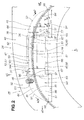
FIG. 2 is an enlarged view showing an area indicated byarrow 2 ofFIG. 1 ; -
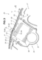
FIG. 3 is a cross-sectional view taken along line 3-3 ofFIG. 1 ; -
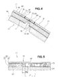
FIG. 4 is a detailed view showing a circledarea 4 ofFIG. 3 ; -
FIG. 5 is a cross-sectional view taken along line 5-5 ofFIG. 2 ; -
FIG. 6 is a view showing the airbag device ofFIG. 2 in an opened state; -
FIG. 7 is a flowchart showing a method for manufacturing the airbag device according to the first embodiment of the present invention; -
FIGS. 8A and 8B are views showing how the base member and the surface member are obtained in the process flow ofFIG. 7 ; -
FIGS. 9A and 9B are views showing how the skin member is fabricated in the process flow ofFIG. 7 ; -
FIGS. 10A and 10B are views showing how the skin member is bonded to the base member in the process flow ofFIG. 7 ; -
FIG. 11 is a schematic view showing a first modification of the airbag device according to the first embodiment of the present invention; -
FIGS. 12A and 12B are schematic views of a second modification of the airbag device according to the first embodiment of the present invention, showing the base member with a patterned irregular part formed on its surface; -
FIG. 13 is a perspective view showing a passenger compartment of a vehicle employing an airbag device according to a second embodiment of the present invention; -
FIG. 14 is a view showing an area indicated byarrow 14 inFIG. 13 ; -
FIG. 15 is a cross-sectional view taken along line 15-15 ofFIG. 13 ; -
FIG. 16 is an enlarged sectional view showing an area indicated byreference numeral 16 inFIG. 15 ; -
FIG. 17 is a cross-sectional view taken along line 17-17 ofFIG. 14 ; -
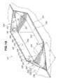
FIG. 18 is a view showing the airbag device according to the second embodiment ofFIG. 14 , in an open state; and -
FIG. 19 is a view showing a modification of the adhesion-adjusted part of the airbag device according to the second embodiment of the present invention. - Referring to
FIGS. 1 through 6 , discussion will now be made as to avehicle airbag device 11 according to a first embodiment of the present invention. Theairbag device 11 is used at thefront passenger seat 13 of avehicle 12. - As shown in
FIG. 1 , thevehicle 12 is provided with avehicle body 21, apassenger compartment 22, adriver seat 23, afront passenger seat 13, awindshield 24, aninstrument panel 25, and anairbag unit 27 that includes theairbag device 11 for thefront passenger seat 13 and anairbag device 26 for thedriver seat 23. - In the
instrument panel 25, atop part 31 on the side where thefront passenger seat 13 is located curves outward in the shape of a gentle sphere with a large radius, andleather 32 is applied to theinstrument panel 25. - As shown in
FIGS. 2 and3 , theairbag device 11 has anenclosure 36 that is provided in anopening 35 formed in an instrument panel main body (base member) 34 of theinstrument panel 25; anairbag 38 accommodated within theenclosure 36; aninflator 37 for deploying theairbag 38; anopenable lid part 41 provided at the top of theenclosure 36; askin member 43 applied to thebase member 34 of thelid part 41 and theinstrument panel 25;outside regions 44 positioned further to the outside than the opening 35 of thebase member 34; and adhesion-adjustedparts 45 formed in theoutside regions 44. - The
lid part 41 is comprised of a first flap (one flap) 51 that is formed in theenclosure 36 via afirst hinge 47; a second flap (other flap) 53 that is formed in theenclosure 36 via a second hinge 52; and a tear line 55 for demarcating thefirst flap 51 and thesecond flap 53. The second hinge 52 and thesecond flap 53 are positioned toward thewindshield 24, and thefirst hinge 47 and thefirst flap 51 are positioned toward the rear of the vehicle 12 (in the direction of the arrow a1). - The
first hinge 47 has afirst hinge shaft 56. The second hinge 52 has asecond hinge shaft 57. Thefirst hinge shaft 56 is positioned at a distance h lower than thesecond hinge shaft 57, and theopening 35 is provided at an angle (average tilt angle θ). - The term "
first hinge shaft 56" refers to a part that is formed at the smallest thickness of thefirst hinge 47, and acts as the supporting point of the hinge. The same applies for thesecond hinge shaft 57. - The tear line 55 has a central tear line 58 that is a weakened part cut as a V-shaped groove in the back of the
lid part 41. - The central tear line 58 is offset an average distance E from the center (W × 50%) of the width W of the
lid part 41, and has a curved shape in which the center of the curve is set towards thefirst hinge 47. Thelid part 41 is divided into thefirst flap 51 and thesecond flap 53 by the breaking of the central tear line 58, and forms a first free end 61 (see alsoFIG. 6 ) of thefirst flap 51, and a second free end 62 (see alsoFIG. 6 ) of thesecond flap 53. Thereference numeral 64 refers to a first side tear line, and thereference numeral 65 refers to a second side tear line. - A plurality of retaining
protrusions 66 for engaging with theinstrument panel 25 is formed in theenclosure 36. - The
first flap 51 is formed as an outward-curving door in which the width W1 from both ends (both end corners) 67 of the first free end 61 to thefirst hinge shaft 56 is minimized. - The
second flap 53 is formed as an inward-curving door provided with the secondfree end 62 that matches the first free end 61. - The
skin member 43 is applied to the outward-curving door (first flap) 51 and the inward-curvingdoor 53 to enhance the design. - In
FIGS. 2 ,3 , and4 , theskin member 43 is comprised of a middle member (space fabric) 72 bonded on thelid part 41 by a skinmember adhesive layer 71, andleather 32 bonded on thespace fabric 72 by aleather adhesive layer 73. - The
space fabric 72 is a cloth or a cloth-resin composite, and astitch holder 76 is formed therein so that a stitchedpart 75 of theleather 32 can be accommodated. The stitchedpart 75 is positioned so as to be disposed at a predetermined distance from thestitch holder 76 when the stitchedpart 75 is accommodated, and a gap is formed between the stitchedpart 75 and thestitch holder 76. A misalignment with respect to thespace fabric 72 and thebase member 34 is thereby allowed. - The
stitch holder 76 is provided in proximity to and along the central tear line 58 on the back of thelid part 41, and is provided on the surface of thelid part 41 and the surface of thebase member 34. - The
leather 32 is artificial or natural leather, the stitchedpart 75 is formed therein by stitchingsecond leather 78 tofirst leather 77, stitches 81 are provided close together along the stitchedpart 75, and the stitchedpart 75 is provided along the central tear line 58 on the back of thelid part 41, and above the central tear line 58. - The stitched
part 75 also acts as a tear part, and the tear part (stitched part) 75 is provided with a lidupper tear part 83 positioned at the top of thelid part 41, and atear seam 84 that connects to the lidtop tear part 83. Specifically, the stitchedpart 75 is provided with thetear seam 84 that is formed so as to extend toward the axis line C 1 (in the direction of the arrow a2) of thefirst hinge shaft 56, in theoutside regions 44 that extend to the lidupper tear part 83 positioned at the top of thelid part 41. - The lid
upper tear part 83 is provided along the weakened part (central tear line) 58. - The stitched
part 75 is formed in a curved shape, and the center of the curve is set toward thefirst hinge 47. - In the
leather 32, a skin opening 91 (seeFIG. 6 ) is formed by the breakage ofthread 86 of the stitchedpart 75 that is positioned at the top of thelid part 41, and theleather 32 has a firstskin detaching part 93 that is connected to one side of theskin opening 91 and that detaches to a predetermined distance Ls, and a secondskin detaching part 94 that is connected to the other side of theskin opening 91 and that detaches to a predetermined distance Ls. - The "detaching of the
skin member 43" refers to the two layers that include theleather 32 and thespace fabric 72 detaching as a body from thebase member 34. - The distances Ls shown in
FIG. 2 are also the lengths of the adhesion-adjustedparts 45, and are set to approximately 1.6 times the width W of thelid part 41. - The adhesion-adjusted
parts 45 are formed to the outside (in the direction of the arrow a3) of one end (the first side tear line 64) of thelid part 41, and to the outside (in the direction of the arrow a4) of the other end (the second side tear line 65) of thelid part 41. - The adhesion-adjusted
parts 45 are provided within triangular regions formed by line segments that pass throughfirst endpoints 95,second endpoints 96, andthird endpoints 97 in plan view, and weakadhesive layers 101 are formed in the triangular regions. - The
first endpoints 95 are endpoints intersected by lines S1 that are positioned at a distance E2 to the outside of the opening 35 (in the direction of the arrow a1) from the axis line C1 of thefirst hinge shaft 56. - The
second endpoints 96 are endpoints that are positioned at a distance L1 to the outside (in the direction of the arrow a5) from the second hinge 52. - The
third endpoints 97 are endpoints that are positioned at a distance E2 to the outside of the opening 35 (in the direction of the arrow a1) from the axis line C1 of thefirst hinge shaft 56. - The same adhesive as in the skin
member adhesive layer 71 is used in these triangular regions, but the weakadhesive layers 101 are formed with the adhesive applied in a different manner. - As shown in
FIGS. 2 and5 , the weakadhesive layers 101 are formed by arranging an adhesive in substantially parallel columns at a pitch P and width Ws on both ends (first side tear line 64) of thelid part 41, and since the surface area in which the adhesive is applied is reduced in comparison to that of the other adhesion region (skin member adhesive layer 71), the adhesion force per unit of surface area is small in comparison to the skinmember adhesive layer 71. The length of the columns is within the aforementioned triangular regions, and the ends of the columns reach S1 and S2. - The "other adhesion region" is the portion bonded by the skin
member adhesive layer 71 outside the triangular regions. - The pitch P and width Ws are approximations, and are within desired ranges (tolerances).
- The operation of the airbag device of the first embodiment will next be described.
- In the
airbag device 11 as shown inFIGS. 1 through 6 , when an impact occurs at the front surface of the vehicle, theinflator 37 is activated based on front-surface impact information. - When the
airbag 38 begins to be deployed by theinflator 37, the stress on thecenter 103 of the central tear line 58 is increased by the deployment force of theairbag 38, and thecenter 103 therefore begins to break at a starting point. - Since the stitched
part 75 also breaks at the same time, theskin opening 91 begins to open. At this time, the stress increases at thecenter 104 of the stitchedpart 75, i.e., at thecenter 104 of the lidupper tear part 83, and breakage begins with thecenter 104 as the starting point. - In the
airbag device 11, breakage can thus be reliably initiated from thecenter 103 of the central tear line 58 and thecenter 104 of the stitchedpart 75, and breakage begins and progresses smoothly. - When tearing has progressed to both ends (both end corners 67) of the central tear line 58, the first
side tear line 64 and the secondside tear line 65 begin to break. - At this time, since the
skin member 43 begins to detach from thebase member 34 provided with the adhesion-adjustedparts 45, and the threads of the stitchedpart 75 break in the firstskin detaching part 93 and secondskin detaching part 94, the firstskin detaching part 93 and the secondskin detaching part 94 begin to open as indicated by the arrows a6 and a7. In other words, detachment of theskin member 43 occurs in the adhesion-adjustedparts 45. - In the adhesion-adjusted
parts 45, since the adhesive is arranged in lines having a predetermined pitch P and width Ws, the adhesion force is small, and the resistance to detachment/opening of theskin member 43 can be reduced. Consequently, the resistance when thefirst flap 51 opens is small, and the deployment direction of theairbag 38 can be restricted. - Then, while the first
side tear line 64 and the secondside tear line 65 continue to be broken by the deploying force of theairbag 38, thefirst flap 51 and the inward-curving doorsecond flap 53 pivot as indicated by the arrows a6 and a7 about the supporting axes of thefirst hinge 47 and the second hinge 52, respectively. - At this time, detachment of the
skin member 43 continues in the adhesion-adjustedparts 45 as described above, but because the adhesive in the adhesion-adjustedparts 45 is arranged in columns at a predetermined pitch P and width Ws, the adhesion is low, and the resistance to detachment/opening of theskin member 43 can be reduced. Consequently, the resistance when thefirst flap 51 opens is small, and the deployment direction of the airbag (bag) 38 can be restricted. - In other words, the
first flap 51 can open wide, and the deployment direction of the airbag (bag) 38 can be restricted to the opening direction (direction of the arrow a6) of thefirst flap 51. - The method for manufacturing the airbag device of the first embodiment will next be described based on
FIGS. 7 through 10 . -
FIG. 7 is a flow diagram showing an overview of the method for manufacturing the airbag device. - Step (hereinafter abbreviated as "ST") 01: The
base member 34 is resin-molded. - ST02: The surface member (leather) 32 is fabricated.
- ST03: The
middle member 72 is fabricated. - ST04: The
skin member 43 is fabricated by bonding the surface member (leather) 32 and themiddle member 72. - ST05: The
skin member 43 is bonded to thebase member 34. - ST01 through ST05 will next be specifically described.
-
FIGS. 8A and 8B show the base member and surface member obtained by the airbag device manufacturing method. The description will also refer toFIGS. 1 through 6 . - The
base member 34 is first resin-molded, as shown inFIG. 8A . Theairbag deployment opening 35, thelid part 41, the tear line 55, and aprotrusion 121 are formed in thebase member 34. - The
leather 32 as the surface member is prepared as shown inFIG. 8B . The leather is cut into the predetermined shapes of thefirst leather 77 and thesecond leather 78. -
FIGS. 9A and 9B show the surface member fabrication step (which includes a tear part positioning step). - The
leather 32 is stitched as shown inFIG. 9A . Thetear part 75 is formed by stitching thefirst leather 77 and thesecond leather 78 withthread 86.Stitches 81 are also provided. - The
middle member 72 is then fabricated. Themiddle member 72 comprised of a fabric material is cut along thebase member 34, and thestitch holder 76 is formed. - The skin member fabrication step is started. The tear part positioning step is performed first. In order to fabricate the
skin member 43, theleather adhesive layer 73 is formed by applying adhesive to themiddle member 72, and theleather 32 is placed on theleather adhesive layer 73. At this time, thetear part 75 that is the stitched part is fitted into thestitch holder 76 of themiddle member 72 as indicated by the arrow b1. - As shown in
FIG. 9B , when thetear part 75 is fitted into thestitch holder 76, thetear part 75 is positioned in themiddle member 72. - In the tear part positioning step, it is sufficient merely to fit the
tear part 75 into thestitch holder 76 as indicated by the arrow b1, and positioning of theleather 32 when theskin member 43 is formed is thus facilitated. - In other words, the positioning of the
tear part 75 in a subsequent step (a downstream step) so as to correspond to the central tear line 58 is facilitated, and the precision of this positioning is easily increased. - Then, when the
leather 32 placed on theleather adhesive layer 73 has been pressed for a predetermined time, theskin member 43 is completed, and the skin member fabrication step is completed. -
FIGS. 10A and 10B show the skin member adhesion step. - The skin
member adhesive layer 71 is first formed by applying adhesive to thebase member 34, and theskin member 43 is placed on the skinmember adhesive layer 71 as shown inFIG. 10A . At this time, thestitch holder 76 provided integrally with theskin member 43 is fitted on theprotrusion 121 of thebase member 34 as indicated by the arrow b2. As shown inFIG. 10B , theskin member 43 is positioned on thebase member 34 when the components are fit together. Specifically, fluctuation can be reduced in the distance J from the central tear line 58 that is the weakened part to thetear part 75. In other words, thetear part 75 is easily provided and affixed along the central tear line 58 while the distance J is maintained. - In the skin member adhesion step, the
stitch holder 76 need only be fitted over theprotrusion 121, as indicated by arrow b2, and thetear part 75 of theskin member 43 is easily positioned with respect to the lid part 41 (central tear line 58). -
FIG. 11 shows theairbag device 11B according to a first modification. The same reference numerals are used to refer to members that are the same as those of the first embodiment. - The
airbag device 11B of the first modification differs with respect to the configuration of the adhesion-adjustedparts 45 described in the first embodiment. - Weak
adhesive layers 101B are formed in the triangular regions in the adhesion-adjustedparts 45B of the first modification. An adhesive is arranged in numerous points at a pitch P in the weakadhesive layers 101B. - Even though the weak
adhesive layers 101B are arranged in points, the same operation and effects are obtained as in theairbag device 11 of the first embodiment. In other words, the deployment direction of theairbag 38 shown inFIG. 3 can be restricted. -
FIGS. 12A and 12B show theairbag device 11C of a second modification that is provided with adhesion-adjustedparts 45C that differ from the adhesion-adjustedparts 45 of the first embodiment. - The adhesion-adjusted
parts 45C of the second modification are comprised of patterned irregular parts 111 that are formed on the surface of thebase member 34 in the triangular regions. Anadhesive layer 112 is formed in the same manner as the skin member adhesive layer 71 (seeFIG. 4 ) of the first embodiment. - The patterned irregular parts 111 are
grooves 113 formed in straight lines substantially parallel to each other at a pitch P3 and depth D at both ends of thelid part 41, the lengths thereof are within the triangular regions, the same as in the first embodiment, and the ends thereof reach the line segments S1 and S2 shown inFIG. 2 . - The
airbag device 11C of the second modification has the same operation and effects as theairbag device 11 of the first embodiment. In other words, the deployment direction of theairbag 38 can be restricted. - The same
adhesive layer 112 as that of the skinmember adhesive layer 71 of the first embodiment is thus formed on the entire surface of themiddle member 72 in the second modification, theadhesive layer 112 can be affixed over the patterned irregular parts 111, and the adhesion operation is easier than in the first embodiment. -
FIGS. 13 through 18 show theairbag device 211 according to a second embodiment. - As shown in
FIG. 13 , thevehicle 212 is provided with avehicle body 221, apassenger compartment 222, adriver seat 223, afront passenger seat 213, a windshield 224, aninstrument panel 225, and anairbag unit 227 that includes theairbag device 211 for thefront passenger seat 213 and anairbag device 226 for thedriver seat 223. -
Leather 232 is applied to theinstrument panel 225. - As shown in
FIGS. 14 and15 , theairbag device 211 is provided with anenclosure 236 that is provided in anopening 235 formed in an instrument panel main body (base member) 234 of theinstrument panel 225; anairbag 238 accommodated within theenclosure 236; aninflator 237 for deploying theairbag 238; anopenable lid part 241 provided at the top of theenclosure 236; askin member 243 applied to thebase member 234 of thelid part 241 and theinstrument panel 225; and adhesion-adjustedparts 245 formed inoutside regions 244 positioned further to the outside than theopening 235 of thebase member 234 - The
lid part 241 is comprised of a first flap (one flap) 251 that is formed in theenclosure 236 via afirst hinge 247; a second flap (other flap) 253 that is formed in theenclosure 236 via asecond hinge 252; and a tear line 255 that is cut in a V shape in the back surface of thefirst flap 251 and thesecond flap 253. - The tear line 255 is formed in the center (W × 50%) of the width W of the
lid part 241, and is comprised of acentral tear line 258 in a straight line that divides thefirst flap 251 and thesecond flap 253; a firstside tear line 264 formed at one end in the longitudinal direction of thelid part 241, thelid part 241 having a total length L; and a secondside tear line 265 formed at the other end. A first free end 261 (seeFIG. 18 ) of thefirst flap 251, and a second free end 262 (seeFIG. 18 ) of thesecond flap 253 are formed by the breaking of thecentral tear line 258. - Retaining
protrusions 266 for engaging with theinstrument panel 225 is formed in theenclosure 236. - In
FIGS. 14 ,15 , and16 , theskin member 243 is comprised of a middle member (space fabric) 272 bonded on thelid part 241 by a skinmember adhesive layer 271, andleather 232 bonded on thespace fabric 272 by a leatheradhesive layer 273. - The
space fabric 272 is a cloth or a cloth-resin composite, for example. A stitch-accommodatingspace 274 is formed so as to substantially coincide with thecentral tear line 258 in order to accommodate a stitched part (tear part) 275 of theleather 232. - The
leather 232 is artificial or natural leather, and the stitchedpart 275 is formed therein by stitchingfirst leather 277 andsecond leather 278.Stitches 281 are provided close to thetear part 275 along both sides of thetear part 275. Thetear part 275 is positioned above thecentral tear line 258 so as to correspond to the position of thecentral tear line 258 formed on the back surface of thelid part 241. - A skin opening 291 (see
FIG. 18 ) is formed by the breakage ofthread 286 of the stitched part (tear part) 275. As shown inFIG. 14 , a firstskin detaching part 293 of thetear part 275 extends in the skin opening 291 a predetermined distance Ln from one endpoint (third endpoint) 297 of thelid part 241, and a secondskin detaching part 294 of thetear part 275 extends in the skin opening 291 a predetermined distance Ln from the other endpoint (third endpoint) of thelid part 241. - The distances Ln shown in
FIG. 14 are also the lengths of the adhesion-adjustedparts 245, and are set to approximately 1.2 times the width W of thelid part 241. - The adhesion-adjusted
parts 245 are formed to the outside (in the direction of the arrow c1) of one end of thelid part 241, and to the outside (in the direction of the arrow c2) of the other end of thelid part 241, and are substantially symmetrical about the symmetry line M. - As shown in
FIG. 14 , the adhesion-adjustedparts 245 are provided within triangular regions formed by line segments that pass throughfirst endpoints 295,second endpoints 296, andthird endpoints 297 in plan view, and weakadhesive layers 301 are formed in the triangular regions. - The
first endpoints 295 are points at a distance Ln to the outside (in the direction of the arrow c1) from the firstside tear line 264 of thelid part 241. - The
second endpoints 296 are a point at a distance L2 to the outside (in the direction of the arrow c3) from thefirst hinge 247, and a point at a distance L2 to the outside (in the direction of the arrow c4) from thesecond hinge 252. - The
third endpoints 297 are positioned at both corners of the firstfree end 261 or the secondfree end 262. - The same adhesive as in the skin member adhesive layer 271 (
FIG. 16 ) is used in these triangular regions, but the weakadhesive layers 301 are formed with the adhesive applied in a different manner. - The length Le of the
skin opening 291 is Le = L + 2Ln. Specifically, Le is the length obtained by adding the total length L of thelid part 241, the length Ln of the firstskin detaching part 293, and the length Ln of the secondskin detaching part 294. In other words, Le is the length between thefirst endpoints parts 245. - The length Lm (
FIG. 1 ) of the stitchedpart 275 is greater than the length Le of the skin opening 291 (Lm > Le), and is the length from the vehicle-width center 224a of theinstrument panel 225 to theleft end 224b. - As shown in
FIGS. 14 and17 , the weakadhesive layers 301 are formed by arranging an adhesive in substantially parallel columns at a pitch P and width Ws at the first and secondside tear lines lid part 241. Since the surface area in which the adhesive is applied is reduced in comparison to that of the other adhesion region (skin member adhesive layer 271), the adhesion force is small in comparison to the skinmember adhesive layer 271. The lengths of the columns of adhesive in the weakadhesive layers 301 are between the line segments S 1 and S2 that form the triangular regions. - An example of the method for manufacturing the
airbag device 211 will next be described. Theairbag device 211 is first fitted into theopening 235 formed in thebase member 234, while thebase member 234 is supported in a fixture. - The skin
member adhesive layer 271 is then formed by applying adhesive to the entire surface of thebase member 234 except for the adhesion-adjustedparts 245. - An application tool to which an adhesive is applied is then placed in the triangular regions of the
base member 234 in which the adhesion-adjustedparts 245 are formed, and aligned weakadhesive layers 301 are formed by removing the application tool. - The
middle member 272 is applied to thebase member 234 to which adhesive has been applied. At this time, theedges middle member 272 are separated to form a groove so that the stitch-accommodatingspace 274 is formed in a position corresponding to thecentral tear line 258 of thebase member 234. -
Pre-stitched leather 232 is then applied to themiddle member 272. Specifically, the adhesive is applied to the entire surface of themiddle member 272, and the leatheradhesive layer 273 is formed. The stitchedpart 275 is then positioned inside the stitch-accommodatingspace 274, and theleather 232 is applied to themiddle member 272. - The operation of the
airbag device 211 of the second embodiment will next be described based onFIGS. 14 through 18 . - In the
airbag device 211, when an impact occurs at the front surface of the vehicle, theinflator 237 is activated based on front-surface impact information. - Deployment of the
airbag 238 is begun by the operation of theinflator 237. Deployment of theairbag 238 causes thecentral tear line 258 to break, and tearing progresses to both ends (thethird endpoints FIG. 14 ) of thecentral tear line 258. At substantially the same time, thethreads 286 of the stitchedpart 275 that are positioned at theskin opening 291 also break, and theskin opening 291 begins to open. - When tearing has progressed to both ends of the
central tear line 258, thecentral tear line 258 is separated by the force of theairbag 238 deploying, and the first and secondside tear lines - At this time, since the
skin member 243 begins to detach from thebase member 234 in the adhesion-adjustedparts 245, and the threads of the stitchedpart 275 break in the first and secondskin detaching parts skin detaching parts FIG. 18 ). - In the adhesion-adjusted
parts 245, since the adhesive is arranged in lines having a predetermined pitch P and width Ws, the adhesion force is small, and the resistance to detachment/opening of theskin member 243 is reduced. Consequently, adverse effects on the deploying properties of theairbag 238 can be reduced. - Then, while the first and second
side tear lines airbag 238, the first andsecond flaps second hinges - At this time, detachment of the
skin member 243 continues in the adhesion-adjustedparts 245 as described above, but the adhesion is low in the adhesion-adjustedparts 245, and theskin member 243 detaches easily. Theairbag 238 therefore deploys smoothly. -
FIG. 19 shows theairbag device 211B according to a modification of theairbag device 211 of the second embodiment. - In the adhesion-adjusted
parts 245B of the modification, weakadhesive layers 301B are formed in the triangular regions, and the adhesive is arranged in numerous points at a pitch P1. - Even though the adhesive in the weak
adhesive layers 301B is arranged in points, the same operation and effects are obtained as in theairbag device 211 of the second embodiment. In other words, the deployment direction of theairbag 238 shown inFIG. 15 can be restricted. - Furthermore, a configuration may be adopted in which patterned irregular parts are formed on the surface of the
base member 234 in the triangular regions, and the patterned irregular parts may be used as adhesion-adjusted parts for application thereon via an adhesive layer, the same as in the second modification of the first embodiment. The length of the patterned irregular parts may also be divided to give a predetermined pitch. - The airbag device of the present invention was adapted in the embodiments to leather used on an instrument panel, but the present invention may also be used in a location other than the instrument panel that is covered by leather.
- An example was described in which the adhesive of the adhesion-adjusted parts is arranged in substantially parallel lines with respect to both ends of the lid part, but the adhesive may also be arranged at a 90° angle so as to be substantially parallel to the longitudinal axis of the lid part, or the adhesive may be arranged at a 45° angle.
- An airbag device wherein a lid part (41) over an opening (35) formed in a base member (34) opens in a suitable opening direction when the airbag is deployed. A tear seam (84) is formed so as to extend along the axis line of a hinge shaft (57) of the lid part in a region (44) further to the outside than the opening. Detaching parts (93, 94) where a skin member (43) on the base member detaches from the base member are provided to the outside region.
Claims (12)
- A vehicle airbag device comprising:a base member (34, 234) having an airbag deployment opening (35, 235) and at least one flap (51, 53) being capable of opening the opening by pivoting about a hinge shaft (56, 57) provided at an edge of the opening;a skin member (43, 243) layered on the base member;a tear seam (84) for breaking in correspondence with the flap by deployment of the airbag (38), the tear seam (84) being formed in the skin member so as to extend toward an axis line of the hinge shaft in a region (44) further to outside than the opening; anddetaching parts (93, 94) formed so as to correspond to the tear seam and so as to be detached from the base member by the flap at which the skin member opens in the outside region of the opening.
- The airbag device of claim 1, wherein the flap comprises two sections; and a pair of hinge shafts corresponding to each of the flaps is provided opposite each other at edges of the opening, the tear seam being formed so as to extend toward the axis line of one hinge shaft (57) of the pair of hinge shafts and away from the other hinge shaft (56).
- The airbag device of claim 2, wherein one (51) of the two flaps is formed as an outward-curving door in which the width from both ends of a free end of the flap to the hinge shaft is minimized, and the other one (53) of the two flaps is formed as an inward-curving door having a shape in which a free end of the flap matches the free end of the one flap.
- The airbag device of claim 1, wherein the flaps are demarcated by a weakened part (58) that is broken by deployment of the airbag, the weakened part being formed in the base member, and the tear part is provided along the weakened part.
- The airbag device of claim 2, wherein the other hinge shaft (56) is provided in a lower position than the one hinge shaft (57), and the opening is provided at an angle.
- The airbag device of claim 1, wherein the region (44, 244) further to the outside than the opening includes an adhesion-adjusted part (45, 245) that is adjusted so that the adhesion between the base member and the skin member is reduced.
- The airbag device of claim 6, wherein the adhesion-adjusted part is adjusted so that a surface area in which an adhesive is applied between the base member and the skin member is smaller than a surface area on which an adhesive is applied in the other outside region.
- The airbag device of claim 6, wherein the adhesion-adjusted part (45) is adjusted by forming a patterned indented part (111) in the base member so that a surface area of contact between the base member and the skin member is smaller than a surface area of contact of the other outside region.
- A method for manufacturing a vehicle airbag device, comprising the steps of:obtaining a base member (34) having an airbag deployment opening (35) and flaps (51, 53) provided at the opening in such a manner as to be capable of opening;layering on the base member a skin member (43) having a stitch-formed tear part (75) for breaking together with the flaps by deployment of the airbag (38);forming a tear seam (84) by arranging the tear part to essentially coincide with free ends of the flaps and to extend to continue to a region outside the flaps; andbonding the skin member to the base member in a state in which an adhesion-adjusted part in which the adhesion is reduced to correspond to the tear seam is provided outside the opening.
- The manufacturing method of claim 9, further comprising the step of placing together and positioning a holder (76) formed in the skin member so as to accommodate the tear part, and a protrusion (121) formed in the base member so as to engage with the holder.
- The manufacturing method of claim 10, further comprising the step of forming a weakened part (58) on a back surface of the base member on which the protrusion is formed, the weakened part (58) being formed along the protrusion.
- The manufacturing method of claim 10, wherein the skin member (43) comprises a surface member (32) to which the tear part (75) is provided, and a middle member (72) layered with the surface member and provided with the holder (76) in which the tear part is accommodated, and the method further comprises the step of placing the tear part of the surface member inside the holder.
Applications Claiming Priority (3)
| Application Number | Priority Date | Filing Date | Title |
|---|---|---|---|
| JP2008064833A JP4580998B2 (en) | 2008-03-13 | 2008-03-13 | Cover body for vehicle airbag device |
| JP2008102543A JP4604108B2 (en) | 2008-04-10 | 2008-04-10 | Airbag device for vehicle |
| JP2008102611A JP4473920B2 (en) | 2008-04-10 | 2008-04-10 | VEHICLE AIRBAG DEVICE AND METHOD FOR MANUFACTURING THE SAME |
Publications (2)
| Publication Number | Publication Date |
|---|---|
| EP2100781A1 true EP2100781A1 (en) | 2009-09-16 |
| EP2100781B1 EP2100781B1 (en) | 2010-04-21 |
Family
ID=40578241
Family Applications (1)
| Application Number | Title | Priority Date | Filing Date |
|---|---|---|---|
| EP09154663A Expired - Fee Related EP2100781B1 (en) | 2008-03-13 | 2009-03-09 | Vehicle airbaig device and method for manufacturing the same |
Country Status (3)
| Country | Link |
|---|---|
| US (1) | US7918481B2 (en) |
| EP (1) | EP2100781B1 (en) |
| DE (1) | DE602009000016D1 (en) |
Cited By (2)
| Publication number | Priority date | Publication date | Assignee | Title |
|---|---|---|---|---|
| EP2716503A4 (en) * | 2011-05-24 | 2014-08-06 | Toyota Motor Co Ltd | INSTRUMENT PANEL HAVING, INTEGRATED, AN INFLATABLE SAFETY CUSHION DOOR |
| FR3072626A1 (en) * | 2017-10-24 | 2019-04-26 | Reydel Automotive B.V. | AIRBAG CHANNEL CLOSURE ASSEMBLY |
Families Citing this family (9)
| Publication number | Priority date | Publication date | Assignee | Title |
|---|---|---|---|---|
| WO2014069654A1 (en) | 2012-11-05 | 2014-05-08 | 豊田合成 株式会社 | Vehicle interior panel and vehicle airbag device |
| JP2014218188A (en) * | 2013-05-09 | 2014-11-20 | 豊田合成株式会社 | Air-bag door for vehicle |
| US9296354B1 (en) | 2015-02-11 | 2016-03-29 | Global Ip Holdings, Llc | Airbag cover assembly including layered, decorative cover pieces held together at a decorative seam |
| JP6628408B2 (en) * | 2016-03-29 | 2020-01-08 | 日本プラスト株式会社 | Cover body of airbag device |
| US9975517B2 (en) | 2016-04-22 | 2018-05-22 | Honda Motor Co., Ltd. | Vehicle restraint apparatus and methods of use and manufacture thereof |
| FR3051417B1 (en) * | 2016-05-17 | 2018-06-29 | Faurecia Interieur Industrie | VEHICLE CLUTCH PANEL PROVIDED FOR HAMING A SAFETY INFLATABLE CUSHION HOUSING |
| EP3814177B1 (en) * | 2018-06-28 | 2025-01-08 | Shanghai Yanfeng Jinqiao Automotive Trim Systems Co. Ltd | Vehicle trim component |
| US11840188B2 (en) * | 2018-06-28 | 2023-12-12 | Shanghai Yanfeng Jinqiao Automotive Trim Systems Co. Ltd. | Vehicle interior component |
| JP7159925B2 (en) * | 2019-03-12 | 2022-10-25 | トヨタ自動車株式会社 | air bag device |
Citations (4)
| Publication number | Priority date | Publication date | Assignee | Title |
|---|---|---|---|---|
| GB2298169A (en) | 1995-02-16 | 1996-08-28 | Daimler Benz Ag | Interior panel for a door with a side impact airbag having a decorative skin backed by a flexible foam and a foam moulding held in a frame. |
| DE19831462A1 (en) * | 1998-07-14 | 2000-01-27 | Johnson Contr Interiors Gmbh | Inner trim for private vehicle's side door equipped with airbag has sealing strip located on two sections of decorative skin covering foam layer and is in region of seam interconnecting the sections |
| EP1520754A1 (en) * | 2003-09-30 | 2005-04-06 | Nihon Plast Co., Ltd. | Airbag cover and its production process |
| DE102006016724A1 (en) * | 2006-04-04 | 2007-10-18 | Faurecia Innenraum Systeme Gmbh | Interior trim part for covering an airbag |
Family Cites Families (12)
| Publication number | Priority date | Publication date | Assignee | Title |
|---|---|---|---|---|
| US4991869A (en) * | 1989-10-02 | 1991-02-12 | General Motors Corporation | Cover assembly for occupant restraint system |
| US5458361A (en) * | 1993-08-25 | 1995-10-17 | Davidson Textron Inc. | Insert for air bag cover assembly |
| US5460402A (en) * | 1995-01-27 | 1995-10-24 | Davidson Textron Inc. | Air bag cover door having a predetermined opening characteristic |
| US5590903A (en) * | 1995-09-29 | 1997-01-07 | Trw Vehicle Safety Systems, Inc. | Deployment door assembly |
| US5775727A (en) * | 1996-01-17 | 1998-07-07 | Trw Vehicle Safety Systems Inc. | Deployment door assembly |
| US6203056B1 (en) * | 1997-06-09 | 2001-03-20 | Textron Automotive Company Inc. | Apparatus for deploying an airbag through a hard panel |
| JPH1159306A (en) | 1997-08-11 | 1999-03-02 | Toyo Tire & Rubber Co Ltd | Air bag device for front passenger seat |
| US6050595A (en) * | 1998-02-19 | 2000-04-18 | Textron Automotive Company Inc. | Peel back method and apparatus for deployably concealing an air bag behind an instrument panel |
| JP4093086B2 (en) | 2003-03-13 | 2008-05-28 | 豊田合成株式会社 | Leather air bag cover |
| JP4368186B2 (en) | 2003-12-03 | 2009-11-18 | 芦森工業株式会社 | Air grid |
| JP4811129B2 (en) | 2006-05-30 | 2011-11-09 | トヨタ自動車株式会社 | Skin-adhesive molded article having an airbag cover and method for producing the same |
| KR100767523B1 (en) * | 2006-08-24 | 2007-10-17 | 현대자동차주식회사 | Passenger airbag door structure |
-
2009
- 2009-03-04 US US12/380,838 patent/US7918481B2/en not_active Expired - Fee Related
- 2009-03-09 DE DE602009000016T patent/DE602009000016D1/en active Active
- 2009-03-09 EP EP09154663A patent/EP2100781B1/en not_active Expired - Fee Related
Patent Citations (4)
| Publication number | Priority date | Publication date | Assignee | Title |
|---|---|---|---|---|
| GB2298169A (en) | 1995-02-16 | 1996-08-28 | Daimler Benz Ag | Interior panel for a door with a side impact airbag having a decorative skin backed by a flexible foam and a foam moulding held in a frame. |
| DE19831462A1 (en) * | 1998-07-14 | 2000-01-27 | Johnson Contr Interiors Gmbh | Inner trim for private vehicle's side door equipped with airbag has sealing strip located on two sections of decorative skin covering foam layer and is in region of seam interconnecting the sections |
| EP1520754A1 (en) * | 2003-09-30 | 2005-04-06 | Nihon Plast Co., Ltd. | Airbag cover and its production process |
| DE102006016724A1 (en) * | 2006-04-04 | 2007-10-18 | Faurecia Innenraum Systeme Gmbh | Interior trim part for covering an airbag |
Cited By (4)
| Publication number | Priority date | Publication date | Assignee | Title |
|---|---|---|---|---|
| EP2716503A4 (en) * | 2011-05-24 | 2014-08-06 | Toyota Motor Co Ltd | INSTRUMENT PANEL HAVING, INTEGRATED, AN INFLATABLE SAFETY CUSHION DOOR |
| US8814207B2 (en) | 2011-05-24 | 2014-08-26 | Toyota Jidosha Kabushiki Kaisha | Instrument panel integrally including an airbag door |
| FR3072626A1 (en) * | 2017-10-24 | 2019-04-26 | Reydel Automotive B.V. | AIRBAG CHANNEL CLOSURE ASSEMBLY |
| WO2019081379A1 (en) * | 2017-10-24 | 2019-05-02 | Reydel Automotive B.V. | Assembly for closing an airbag channel |
Also Published As
| Publication number | Publication date |
|---|---|
| US7918481B2 (en) | 2011-04-05 |
| EP2100781B1 (en) | 2010-04-21 |
| DE602009000016D1 (en) | 2010-06-02 |
| US20090230660A1 (en) | 2009-09-17 |
Similar Documents
| Publication | Publication Date | Title |
|---|---|---|
| EP2100781B1 (en) | Vehicle airbaig device and method for manufacturing the same | |
| CN101531172B (en) | Vehicle airbag device and manufacturing method thereof | |
| KR101579065B1 (en) | Vehicular trim applications using film adhesive in lieu of stitching | |
| JP4473920B2 (en) | VEHICLE AIRBAG DEVICE AND METHOD FOR MANUFACTURING THE SAME | |
| JP3944245B2 (en) | Method for producing a finished part including a zone designed to generate a passage, and the finished part and assembly produced thereby | |
| KR100890774B1 (en) | Car airbag door | |
| JP4523940B2 (en) | Interior parts for covering airbags | |
| US8376395B2 (en) | Airbag flap arrangement hinged on a dashboard | |
| US9260074B2 (en) | Vehicle interior panel and vehicle airbag apparatus | |
| WO2014069654A1 (en) | Vehicle interior panel and vehicle airbag device | |
| US7025374B2 (en) | Airbag cover and tear seam | |
| US7384061B2 (en) | Trim panel and a method of manufacture | |
| US8100431B2 (en) | Front passenger seat airbag apparatus | |
| EP4520600B1 (en) | Vehicle interior panel for use over an airbag | |
| CN118238761A (en) | Decorative parts | |
| EP1946979A1 (en) | Airbag cover with controlled tear lines | |
| JP4604108B2 (en) | Airbag device for vehicle | |
| CN101423046B (en) | Vehicular instrument panel | |
| JP3937296B2 (en) | Airbag door opening structure | |
| US11932193B1 (en) | Vehicle interior panel for use over a deployable airbag and method of manufacturing | |
| US12257970B1 (en) | Vehicle interior panel with folded hinge layer | |
| EP4375148B1 (en) | Passenger air bag device | |
| JP4610998B2 (en) | Instrument panel with integrated airbag door | |
| JP2007030841A (en) | Airbag door | |
| JP2024039781A (en) | Vehicle interior panels |
Legal Events
| Date | Code | Title | Description |
|---|---|---|---|
| PUAI | Public reference made under article 153(3) epc to a published international application that has entered the european phase |
Free format text: ORIGINAL CODE: 0009012 |
|
| 17P | Request for examination filed |
Effective date: 20090309 |
|
| AK | Designated contracting states |
Kind code of ref document: A1 Designated state(s): AT BE BG CH CY CZ DE DK EE ES FI FR GB GR HR HU IE IS IT LI LT LU LV MC MK MT NL NO PL PT RO SE SI SK TR |
|
| AX | Request for extension of the european patent |
Extension state: AL BA RS |
|
| GRAP | Despatch of communication of intention to grant a patent |
Free format text: ORIGINAL CODE: EPIDOSNIGR1 |
|
| GRAS | Grant fee paid |
Free format text: ORIGINAL CODE: EPIDOSNIGR3 |
|
| GRAA | (expected) grant |
Free format text: ORIGINAL CODE: 0009210 |
|
| AK | Designated contracting states |
Kind code of ref document: B1 Designated state(s): DE FR GB |
|
| REG | Reference to a national code |
Ref country code: GB Ref legal event code: FG4D |
|
| AKX | Designation fees paid |
Designated state(s): DE FR GB |
|
| REF | Corresponds to: |
Ref document number: 602009000016 Country of ref document: DE Date of ref document: 20100602 Kind code of ref document: P |
|
| PLBE | No opposition filed within time limit |
Free format text: ORIGINAL CODE: 0009261 |
|
| STAA | Information on the status of an ep patent application or granted ep patent |
Free format text: STATUS: NO OPPOSITION FILED WITHIN TIME LIMIT |
|
| 26N | No opposition filed |
Effective date: 20110124 |
|
| REG | Reference to a national code |
Ref country code: GB Ref legal event code: 746 Effective date: 20131107 |
|
| REG | Reference to a national code |
Ref country code: DE Ref legal event code: R084 Ref document number: 602009000016 Country of ref document: DE Effective date: 20131113 |
|
| REG | Reference to a national code |
Ref country code: FR Ref legal event code: PLFP Year of fee payment: 7 |
|
| PGFP | Annual fee paid to national office [announced via postgrant information from national office to epo] |
Ref country code: DE Payment date: 20150305 Year of fee payment: 7 |
|
| PGFP | Annual fee paid to national office [announced via postgrant information from national office to epo] |
Ref country code: FR Payment date: 20150309 Year of fee payment: 7 Ref country code: GB Payment date: 20150304 Year of fee payment: 7 |
|
| REG | Reference to a national code |
Ref country code: DE Ref legal event code: R119 Ref document number: 602009000016 Country of ref document: DE |
|
| GBPC | Gb: european patent ceased through non-payment of renewal fee |
Effective date: 20160309 |
|
| REG | Reference to a national code |
Ref country code: FR Ref legal event code: ST Effective date: 20161130 |
|
| PG25 | Lapsed in a contracting state [announced via postgrant information from national office to epo] |
Ref country code: GB Free format text: LAPSE BECAUSE OF NON-PAYMENT OF DUE FEES Effective date: 20160309 Ref country code: FR Free format text: LAPSE BECAUSE OF NON-PAYMENT OF DUE FEES Effective date: 20160331 Ref country code: DE Free format text: LAPSE BECAUSE OF NON-PAYMENT OF DUE FEES Effective date: 20161001 |