EP2100532B1 - Reißverschluss und oberer Anschlag für einen Reißverschluss - Google Patents
Reißverschluss und oberer Anschlag für einen Reißverschluss Download PDFInfo
- Publication number
- EP2100532B1 EP2100532B1 EP08004703A EP08004703A EP2100532B1 EP 2100532 B1 EP2100532 B1 EP 2100532B1 EP 08004703 A EP08004703 A EP 08004703A EP 08004703 A EP08004703 A EP 08004703A EP 2100532 B1 EP2100532 B1 EP 2100532B1
- Authority
- EP
- European Patent Office
- Prior art keywords
- puller
- slider
- top stop
- slide fastener
- stop
- Prior art date
- Legal status (The legal status is an assumption and is not a legal conclusion. Google has not performed a legal analysis and makes no representation as to the accuracy of the status listed.)
- Not-in-force
Links
Images


Classifications
-
- A—HUMAN NECESSITIES
- A44—HABERDASHERY; JEWELLERY
- A44B—BUTTONS, PINS, BUCKLES, SLIDE FASTENERS, OR THE LIKE
- A44B19/00—Slide fasteners
- A44B19/24—Details
- A44B19/26—Sliders
- A44B19/30—Sliders with means for locking in position
- A44B19/301—Sliders with means for locking in position at the end of their upward travel with any suitable device, e.g. pull member combined with a press-button, a hook, a key-operated lock
-
- A—HUMAN NECESSITIES
- A44—HABERDASHERY; JEWELLERY
- A44B—BUTTONS, PINS, BUCKLES, SLIDE FASTENERS, OR THE LIKE
- A44B19/00—Slide fasteners
- A44B19/24—Details
- A44B19/32—Means for making slide fasteners gas or watertight
-
- Y—GENERAL TAGGING OF NEW TECHNOLOGICAL DEVELOPMENTS; GENERAL TAGGING OF CROSS-SECTIONAL TECHNOLOGIES SPANNING OVER SEVERAL SECTIONS OF THE IPC; TECHNICAL SUBJECTS COVERED BY FORMER USPC CROSS-REFERENCE ART COLLECTIONS [XRACs] AND DIGESTS
- Y10—TECHNICAL SUBJECTS COVERED BY FORMER USPC
- Y10T—TECHNICAL SUBJECTS COVERED BY FORMER US CLASSIFICATION
- Y10T24/00—Buckles, buttons, clasps, etc.
- Y10T24/25—Zipper or required component thereof
- Y10T24/2511—Zipper or required component thereof with distinct, stationary means for anchoring slider
- Y10T24/2513—Zipper or required component thereof with distinct, stationary means for anchoring slider and for aligning surfaces or obstructing slider movement
Definitions
- the present invention refers to a slide fastener and to a top stop of a slide fastener.
- the invention relates in particular to fluid-tight slide fasteners and top stops of fluid-tight slide fasteners.
- a slide fastener in essential terms, comprises a pair of tapes bearing respective rows of teeth, top and bottom stops, and a slider for opening and closing the fastener by engaging and disengaging the teeth.
- the slider is operated by a puller (or pull-tab) which is usually connected to the slider by a ring or a ring shaped end portion of the same puller.
- top and bottom stops are at opposite ends of the slide fastener, which is completely closed when the slider reaches the top-stop.
- Fluid-tight slide fasteners are used in sports and outdoor activity items, diving or sailing suits, camping tents and the like, and are required to securely prevent the passage of a liquid and/or gas, e.g. water and/or air.
- a fluid-tight fastener must ensure fluid-tightness even under a significant pressure difference between the interior and the exterior, for example up to about 2 bars.
- Fluid-tight slide fasteners are realized for example with layered tapes made of a textile core with a waterproof coating layer, and injection-molded teeth.
- the slider of a slide fastener comprises upper and lower blades, lateral flanges and a central portion, called diamond, connecting the upper and lower blades.
- the top stop is a substantially U-shaped element with leg portions defining a front opening for the diamond of the slider, and a seat for receiving said diamond when the slide fastener is fully closed. It is known technique to provide a suitable shape of the lateral flanges of the slider so that they act on the sides of said leg portions of the U-shaped top stop, in order to close said front opening in a fluid-tight manner when the slider reaches the full-closed position.
- the slider in order to guarantee the fluid-tightness of the closed slide fastener, during the use, the slider should be kept in position and prevented from moving away from the top stop. In fact, an accidental displacement of the slider, even of few tenths of a millimeter, may compromise the fluid-tightness of the fastener at the region of the top stop and/or between the teeth.
- GB 2 200 220 discloses a slide fastener where locking of the pull tab is effected by insertion of a protrusion of the top stop into an aperture of the pull tab, and reliable locking is obtained by inserting a locking pin into an engagement hole of said protrusion. This system however does not allow a quick and easy opening.
- the technical problem underlying the invention is to provide a reliable and safe closure of a slide fastener as defined above, avoiding the slider from leaving the position where the fastener is fully closed, allowing at the same time a quick and easy opening of the fastener itself.
- a slide fastener comprising a pair of tapes, carrying respective teeth, a top stop and a slider comprising a puller, said puller having a ring for connection to the slider, the slider being movable up to a closing position of the fastener where said slider is in contact with said top stop, the top stop comprising at least one retaining element adapted to retain the slider in said closing position, characterized in that said retaining element is disposed to act as a stop means for the slider when said puller is fitted on the top stop in a determined locking position, and in that the top stop comprises at least one locking element, adapted to a snap engagement with a suitable seat or portion of the puller, to retain the puller in said locking position, said at least one locking element being an elastically deformable element adapted to snap on said ring connecting the puller to the slider.
- said at least one retaining element is integrally formed with the top stop.
- Said retaining element is disposed to act as a stop means for the slider when the puller is fitted on the top stop in a determined locking position.
- said locking position is a position where the puller is lying on the top stop, substantially parallel to the sliding direction of the slider.
- a retaining element is integrally formed with the top stop, having a surface disposed to act as a stop means against a contact face of the puller, when the puller is fitted on the top stop in said locking position.
- the top stop comprises at least one locking element, adapted to a snap engagement with a suitable seat or portion of the puller, to retain the puller in said locking position, said seat or portion of the puller is a ring or a ring portion connecting the puller to the slider, said at least one locking element is an elastically deformable element adapted to snap on the ring connecting the puller to the slider.
- said locking element has an elastically deformable stem portion and a head portion projected from top of the stem portion, defining an undercut recess for receiving the ring of the puller.
- Said locking element(s), according to the invention are able to engage/disengage the ring of the slider by elastic deformation induced by contact with the ring itself when the puller is locked or unlocked on the top stop.
- the head portion of the locking elements has a suitably profiled surface to allow deformation of the element by contact with the ring of the slider, while the puller is pressed down to the locking position, or lifted from that position. Thanks to said profiled surface, contact with the ring of the puller results in a force directed to deform the locking element(s) in such a way to receive or, respectively, to free the ring of the puller, as will be clearer hereinbelow with the help of an example.
- said at least one retaining element of the top stop is formed as a wall of the top stop, comprising a base part with a surface adapted to act as a stop means against a contact face of the puller, and two locking elements formed as elastically deformable toothed elements projecting upwards from said base part and each defining an undercut recess for receiving the ring of the puller.
- the base part of the wall integrally formed with the top stop has a front surface facing the slider and a rear surface adapted to act as a stop means against a bottom face of the puller, to retain the slider when the puller is in the locking position.
- the top stop comprises at least one pin adapted to engage a corresponding hole of the puller, to retain the puller from lateral movement.
- An object of the invention is also a top stop for a slide fastener, according to claim 11.
- the invention provides a top stop for a slide fastener wherein said at least one retaining element is formed as a front wall of the top stop, the top stop being adapted to receive the puller of the slider in a locking position, said front wall comprising a surface adapted to act as a stop means against a contact face of the puller when the puller is fitted in said locking position.
- the invention has the advantage that the slider is securely kept in the closing position It should be noted that the snap-on engagement between the locking elements and the slider, namely the puller thereof, provides a quick and simple locking/unlocking action, so that the slider of the fastener is securely kept in the closing position and presented from accidental opening even under intensive use, but the user can open the fastener rapidly and easily at any time.
- the invention is particularly useful in a fluid-tight fastener, where a small deviation of the slider from the full-closing position may compromise the fluid-tightness.
- an item fitted with a slide fastener according to the invention such as a sports garment or the like, gives reliable fluid-tight performance with easy and safe use.
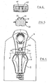
- Fig. 1 shows a top portion of a slide fastener 1, in accordance with a preferred embodiment of the invention, comprising a pair of tapes 2, equipped with teeth 3, a top stop 4, and a slider 5 with a puller 6.
- the puller 6 is connected to the slider 5 by a ring 7.
- the slider 5 is movable in a sliding direction, parallel to tapes 2, up to a closing position where the slide fastener 1 is fully closed, i.e. all teeth 3 are engaged and the slider 5 is in contact with the top stop 4. Said closing position is shown in Fig. 1 .
- tapes 2 an teeth 3 can be according to known art and are not discussed in detail.
- tapes 2 are made of a textile core layer fully coated on both sides by a suitable waterproof layer and teeth 3 are injection-molded on tapes 2.
- the top stop 4, in a fluid-tight slide fastener, can also be injection-molded on tapes 2.
- the slider 5 ( Fig. 2 ) substantially comprises upper and lower blades 8, 9 with lateral flanges 10, 11 on both sides, and a diamond connecting said upper and lower blades 8, 9.
- the puller 6 can be fitted from the position of normal use, as seen in Fig. 1 and 2 , to a locking position on the top stop 4, shown in Figs. 3 and 4 . In said locking position, the puller 6 is lying on the top stop 4, substantially parallel to the sliding direction of the slider 5.
- a front wall 20 is integrally formed in the top stop 4, acting as a stop means against a bottom contact face 30 of the puller 6.
- the wall 20 has a rear surface 32 ( Fig. 2 ) acting as a stop means against the contact face 30 of the puller 6, when in position of Figs. 3-4 .
- the wall 20 has a front surface 31 facing the slider; advantageously, there is a gap between said front surface 31 and the slider 5 for clearance recovery.
- the contact face 30 may be slightly curved and, in this case, the rear surface 32 of wall 20 is curved accordingly ( Fig. 4 ).
- Two toothed elements 22, 23 project upwards from the central portion of base part 21 of the wall 20, adapted to mechanically engage the ring 7 in order to "lock" the puller 6 in the position of Figs. 3-4 .
- Each of said elements 22 and 23 has an elastically deformable stem portion projecting upwards from the base 21, and a head portion defining an undercut recess 29 for receiving the ring 7 when the puller is in the locking position.
- each of elements 22, 23 has a stem portion 24 projecting upwards from base part 21 of the wall 20, and carrying a head portion 25 projecting laterally and outward from the top of the stem 24, defining inclined surfaces 26 and 27 converging to an edge 28, and the undercut recess 29 below said edge 28 and between the base 21 and the head 25 itself.
- Pressing the ring 7 against faces 26 or 27 has the effect of bending laterally and inwards the stem portion 24 of the toothed elements 22 and 23, thus engaging the ring 7 in the recess 29 or vice-versa disengaging the same ring 7 and puller 6 from the looking position.
- the top stop 4 also comprises a pin 40 which is received in a corresponding hole 41 of the puller 6, when the puller 6 is in said locking position. Said pin 40, received in the hole 41, retains the puller 6 from lateral movement.
- the pin 40 is elliptical and frusto-conical, with a cross action decreasing from base to top.
- the pin 40 may also be cylindrical in simpler embodiments.
- the puller 6 may also be shaped in a different manner, for example with a hole in the bottom part defining a ring portion connecting the puller with the slider 5.
- the retaining element rather than wall 20, may be realized in different ways, including a plastic or metal element not integrally formed with the top stop itself.
- the user lowers the pull-tab 6 from the position of use of Figs. 1-2 to the locked position of Figs. 3-4 .
- the ring 7 contacts the upper surfaces 26 of teeth 22, 23 ( Fig. 2 ), and due to inclination of said surfaces 26, the stems 24 are deformed until the ring 7 can overcome the edge 28, and reach the undercut recesses 29.
- the fastener is unlocked by lifting the puller 6, so that the ring 7 bends the elements 22, 23 pressing against the contact surfaces 27, until the ring 7 itself reaches the edge 28 and is freed to the use position of Figs. 1-2 again. Then, the user can open the slide fastener 1 as usual.
- the puller 6 is locked and unlocked manually and in a quick and immediate way by lowering or, respectively, lifting the puller. Notwithstanding this, when the puller 6 is locked the slider 5 is firmly secured on the top stop 4, and accidental opening of the fastener and/or loss of the fluid-tightness is prevented in a reliable way.
Landscapes
- Slide Fasteners (AREA)
- Portable Nailing Machines And Staplers (AREA)
- Vehicle Step Arrangements And Article Storage (AREA)
- Sheet Holders (AREA)
- Bag Frames (AREA)
Claims (11)
- Reißverschluss (1), der zwei Bänder (2), die jeweilige Zähne (3) tragen, einen oberseitigen Anschlag (4) und einen Schieber (5) mit einem Zugorgan (6) umfasst, wobei das Zugorgan (6) einen Ring (7) zur Verbindung mit dem Schieber (5) aufweist, und der Schieber (5) bis zu einer Schließposition des Reißverschlusses (1) bewegbar ist, in der der Schieber (5) in Kontakt mit dem oberseitigen Anschlag (4) steht, wobei der oberseitige Anschlag (4) mindestens ein Halteelement (20) aufweist, das dazu angepasst ist, den Schieber (5) in der Schließposition zu halten, dadurch gekennzeichnet, dass das Halteelement (20) vorgesehen ist, um als Anschlageinrichtung für den Schieber (5) zu wirken, wenn das Zugorgan (6) am oberseitigen Anschlag (4) in einer festgelegten Verriegelungsposition eingerastet ist, und der oberseitige Anschlag mindestens ein Verriegelungselement aufweist, das dazu angepasst ist, mit einer geeigneten Aufnahme oder einem geeigneten Abschnitt des Zugorgans (6) in Schnappeingriff zu gelangen, um das Zugorgan in der Verriegelungsposition zu halten, wobei es sich bei dem mindestens einen Verriegelungselement um ein elastisch verformbares Element (22, 23) handelt, das dazu angepasst ist, am Ring (7) einzuschnappen, der das Zugorgan mit dem Schieber verbindet.
- Reißverschluss nach Anspruch 1, wobei das mindestens eine Halteelement (20) einstückig mit dem oberseitigen Anschlag (4) ausgebildet ist.
- Reißverschluss nach Anspruch 1 oder 2, wobei die festgelegte Verriegelungsposition des Zugorgans (6) eine Position ist, in der das Zugorgan (6) am oberseitigen Anschlag (4) anliegt, und zwar im Wesentlichen parallel zur Schieberichtung des Schiebers (5) entlang des Reißverschlusses (1).
- Reißverschluss nach Anspruch 2 oder 3, wobei das Halteelement (20) eine Fläche (32) aufweist, die dazu angepasst ist, als Anschlageinrichtung für eine Kontaktfläche (30) des Zugorgans (6) zu wirken.
- Reißverschluss nach einem der Ansprüche 1 bis 4, wobei das mindestens eine Verriegelungselement als Zahnelement (22, 23) ausgebildet ist, das dazu angepasst ist, am Ring (7) einzuschnappen, der das Zugorgan (6) mit dem Schieber (5) verbindet.
- Reißverschluss nach Anspruch 5, wobei das Zahnelement (22, 23) mit einem elastisch verformbaren Basisabschnitt (24) und einem Kopfabschnitt (25) ausgebildet ist, wobei der Kopfabschnitt von der Oberseite des Basisabschnitts (24) vorsteht und eine hinterschnittene Aussparung (29) zur Aufnahme des Rings (7) des Zugorgans (6) bildet.
- Reißverschluss nach Anspruch 6, wobei das mindestens eine Halteelement des oberseitigen Anschlags als Vorderwand (20) des oberseitigen Anschlags (4) ausgebildet ist, mit einem Basisteil (21) mit einer Fläche (32), die dazu angepasst ist, als Anschlageinrichtung für eine Kontaktfläche (30) des Zugorgans (6) zu wirken, und zwei elastisch verformbaren Zahnelementen (22, 23) zum Arretieren des Zugorgans (6) in einer Verriegelungsposition, wobei die Elemente (22, 23) vom Basisteil (21) nach oben vorstehen und jeweils eine hinterschnittene Aussparung (29) zur Aufnahme des Rings (7) des Zugorgans (6) bilden.
- Reißverschluss nach einem der vorhergehenden Ansprüche, dadurch gekennzeichnet, dass der oberseitige Anschlag (4) mindestens einen Stift (40) aufweist, der dazu angepasst ist, in eine entsprechende Öffnung (41) des Zugorgans (6) einzugreifen.
- Reißverschluss nach einem der vorhergehenden Ansprüche, wobei der Reißverschluss (1) fluiddicht ist.
- Gegenstand wie zum Beispiel ein Sportanzug oder dergleichen, der einen Reißverschluss nach einem der Ansprüche 1 bis 9 aufweist.
- Oberseitiger Anschlag (4) für einen Reißverschluss (1), wobei der Reißverschluss einen Schieber (5) mit einem Zugorgan (6) umfasst, und der oberseitige Anschlag (4) mindestens ein Halteelement aufweist, das dazu angepasst ist, den Schieber (5) in einer Schließposition zu halten, wobei der oberseitige Anschlag dadurch gekennzeichnet ist, dass das mindestens eine Halteelement (20) vorgesehen ist, um als Anschlageinrichtung für den Schieber (5) des Reißverschlusses (1) zu wirken, wenn das Zugorgan (6) am oberseitigen Anschlag (4) in einer festgelegten Verriegelungsposition eingerastet ist, und der oberseitige Anschlag (4) mindestens ein Verriegelungselement aufweist, das dazu angepasst ist, mit einer geeigneten Aufnahme oder einem geeigneten Abschnitt des Zugorgans in Schnappeingriff zu gelangen, um das Zugorgan in der Verriegelungsposition zu halten, wobei es sich bei dem mindestens einen Verriegelungselement um ein elastisch verformbares Element (22, 23) handelt, das dazu angepasst ist, am Ring (7) einzuschnappen, der das Zugorgan (6) mit dem Schieber (5) verbindet.
Priority Applications (11)
| Application Number | Priority Date | Filing Date | Title |
|---|---|---|---|
| DE602008003971T DE602008003971D1 (de) | 2008-03-13 | 2008-03-13 | Reißverschluss und oberer Anschlag für einen Reißverschluss |
| AT08004703T ATE491360T1 (de) | 2008-03-13 | 2008-03-13 | REIßVERSCHLUSS UND OBERER ANSCHLAG FÜR EINEN REIßVERSCHLUSS |
| EP08004703A EP2100532B1 (de) | 2008-03-13 | 2008-03-13 | Reißverschluss und oberer Anschlag für einen Reißverschluss |
| ES08004703T ES2356862T3 (es) | 2008-03-13 | 2008-03-13 | Cierre deslizante y tope superior para cierre deslizante. |
| US12/402,070 US20090229090A1 (en) | 2008-03-13 | 2009-03-11 | Slide Fastener and a Top Stop for a Slide Fastener |
| AU2009200998A AU2009200998B2 (en) | 2008-03-13 | 2009-03-11 | A slide fastener and a top stop for a slide fastener |
| CA002657897A CA2657897A1 (en) | 2008-03-13 | 2009-03-11 | A slide fastener and a top stop for a slide fastener |
| NZ575523A NZ575523A (en) | 2008-03-13 | 2009-03-13 | A slide fastener where the puller interacts with the top stop to lock the slider when the fastener is fully closed |
| CN200910119416.4A CN101554258B (zh) | 2008-03-13 | 2009-03-13 | 拉链以及用于拉链的上止 |
| JP2009060857A JP2009219872A (ja) | 2008-03-13 | 2009-03-13 | スライドファスナおよびスライドファスナの上部ストッパ |
| HK09111747.4A HK1134227A1 (en) | 2008-03-13 | 2009-12-15 | A slide fastener and a top stop for a slide fastener |
Applications Claiming Priority (1)
| Application Number | Priority Date | Filing Date | Title |
|---|---|---|---|
| EP08004703A EP2100532B1 (de) | 2008-03-13 | 2008-03-13 | Reißverschluss und oberer Anschlag für einen Reißverschluss |
Publications (2)
| Publication Number | Publication Date |
|---|---|
| EP2100532A1 EP2100532A1 (de) | 2009-09-16 |
| EP2100532B1 true EP2100532B1 (de) | 2010-12-15 |
Family
ID=39638844
Family Applications (1)
| Application Number | Title | Priority Date | Filing Date |
|---|---|---|---|
| EP08004703A Not-in-force EP2100532B1 (de) | 2008-03-13 | 2008-03-13 | Reißverschluss und oberer Anschlag für einen Reißverschluss |
Country Status (11)
| Country | Link |
|---|---|
| US (1) | US20090229090A1 (de) |
| EP (1) | EP2100532B1 (de) |
| JP (1) | JP2009219872A (de) |
| CN (1) | CN101554258B (de) |
| AT (1) | ATE491360T1 (de) |
| AU (1) | AU2009200998B2 (de) |
| CA (1) | CA2657897A1 (de) |
| DE (1) | DE602008003971D1 (de) |
| ES (1) | ES2356862T3 (de) |
| HK (1) | HK1134227A1 (de) |
| NZ (1) | NZ575523A (de) |
Families Citing this family (12)
| Publication number | Priority date | Publication date | Assignee | Title |
|---|---|---|---|---|
| US8484764B2 (en) | 2010-08-18 | 2013-07-16 | Under Armour, Inc. | Zipper arrangement |
| US8341809B2 (en) | 2010-11-16 | 2013-01-01 | Under Armour, Inc. | Zipper arrangement with funnel grip |
| US8528115B2 (en) | 2010-11-16 | 2013-09-10 | Under Armour, Inc. | Zipper arrangement with foldable pull |
| US8484811B2 (en) | 2010-11-16 | 2013-07-16 | Under Armour, Inc. | Zipper arrangement with wheeled slider |
| ITMO20110335A1 (it) * | 2011-12-29 | 2013-06-30 | Micron Plast Societa A Responsab Ilita Limitat | Dispositivo di apertura e chiusura perfezionato per cerniere a pressione. |
| CN105682502B (zh) * | 2013-10-31 | 2019-03-12 | Ykk株式会社 | 拉链 |
| EP2959789B1 (de) | 2014-06-25 | 2019-05-15 | J&P Coats Limited | Reissverschluss |
| US10575601B2 (en) | 2015-10-02 | 2020-03-03 | Under Armour, Inc. | Stop for zipper arrangement |
| CN106723698A (zh) * | 2017-03-10 | 2017-05-31 | 惠安惠诚手袋有限公司 | 防水气密性拉链 |
| CN109229823B (zh) * | 2018-06-27 | 2020-02-07 | 浙江自由家居用品制造有限公司 | 一种能够灵活收纳的u型枕收纳袋 |
| CN208523931U (zh) * | 2018-07-16 | 2019-02-22 | 芊茂(浙江)拉链有限公司 | 可互锁的左右上止结构 |
| CN112741400B (zh) * | 2020-12-10 | 2022-03-25 | 福建浔兴拉链科技股份有限公司 | 一种防盗拉链及其应用 |
Family Cites Families (19)
| Publication number | Priority date | Publication date | Assignee | Title |
|---|---|---|---|---|
| US2193827A (en) * | 1937-07-27 | 1940-03-19 | Whitehall Patents Corp | Locking top stop for separable fasteners |
| US2836872A (en) * | 1956-01-30 | 1958-06-03 | Luglio Theodore Di | Retaining attachment for a slide fastener |
| JPS548884Y2 (de) * | 1972-03-21 | 1979-04-24 | ||
| GB1543380A (en) * | 1976-02-18 | 1979-04-04 | Versapak Ltd | Reusable envelope |
| US4081882A (en) * | 1976-11-01 | 1978-04-04 | Coats & Clark, Inc. | Locking zipper slider, and zipper incorporating said slider |
| GB2000220B (en) * | 1977-06-23 | 1982-03-31 | Yoshida Kogyo Kk | Device for locking a slider of a slide fastener |
| JPS5540704U (de) * | 1978-09-08 | 1980-03-15 | ||
| JPS6195314U (de) * | 1984-11-29 | 1986-06-19 | ||
| JP2512769Y2 (ja) * | 1989-06-16 | 1996-10-02 | ワイケイケイ株式会社 | スライドファスナ―用錠装置 |
| US5031286A (en) * | 1990-08-29 | 1991-07-16 | Talon, Inc. | Slider for a slide fastener |
| JP3396346B2 (ja) * | 1995-01-31 | 2003-04-14 | ワイケイケイ株式会社 | スライドファスナー用スライダー |
| US5681115A (en) * | 1996-01-02 | 1997-10-28 | Diederich; R. David | Child-resistant locking device for reclosable bag |
| JP2001072088A (ja) * | 1999-09-08 | 2001-03-21 | Axis:Kk | 封緘具および封緘方法 |
| US6237199B1 (en) * | 1999-11-26 | 2001-05-29 | Wallace Lien Chou Wang | Zipper slide with means for restraining pull tab thereof from swinging |
| CN2512295Y (zh) * | 2001-07-16 | 2002-09-25 | 洪建设 | 拉链 |
| JP3733309B2 (ja) * | 2001-09-25 | 2006-01-11 | Ykk株式会社 | スライドファスナー用スライダー |
| JP2005087705A (ja) * | 2003-09-19 | 2005-04-07 | Mamoru Okamoto | スナップボタン付きスライドファスナー用引手 |
| JP4149369B2 (ja) * | 2003-12-10 | 2008-09-10 | Ykk株式会社 | 自動停止装置付スライドファスナー用スライダー |
| TWM315517U (en) * | 2006-09-22 | 2007-07-21 | Swepo Co Ltd | Zipper head structure |
-
2008
- 2008-03-13 ES ES08004703T patent/ES2356862T3/es active Active
- 2008-03-13 DE DE602008003971T patent/DE602008003971D1/de active Active
- 2008-03-13 EP EP08004703A patent/EP2100532B1/de not_active Not-in-force
- 2008-03-13 AT AT08004703T patent/ATE491360T1/de not_active IP Right Cessation
-
2009
- 2009-03-11 AU AU2009200998A patent/AU2009200998B2/en not_active Ceased
- 2009-03-11 US US12/402,070 patent/US20090229090A1/en not_active Abandoned
- 2009-03-11 CA CA002657897A patent/CA2657897A1/en not_active Abandoned
- 2009-03-13 JP JP2009060857A patent/JP2009219872A/ja active Pending
- 2009-03-13 NZ NZ575523A patent/NZ575523A/en not_active IP Right Cessation
- 2009-03-13 CN CN200910119416.4A patent/CN101554258B/zh not_active Expired - Fee Related
- 2009-12-15 HK HK09111747.4A patent/HK1134227A1/xx not_active IP Right Cessation
Also Published As
| Publication number | Publication date |
|---|---|
| AU2009200998A1 (en) | 2009-10-01 |
| CN101554258A (zh) | 2009-10-14 |
| ES2356862T8 (es) | 2011-07-12 |
| NZ575523A (en) | 2010-07-30 |
| CA2657897A1 (en) | 2009-09-13 |
| ATE491360T1 (de) | 2011-01-15 |
| AU2009200998B2 (en) | 2012-12-20 |
| DE602008003971D1 (de) | 2011-01-27 |
| CN101554258B (zh) | 2012-04-18 |
| JP2009219872A (ja) | 2009-10-01 |
| ES2356862T3 (es) | 2011-04-13 |
| EP2100532A1 (de) | 2009-09-16 |
| HK1134227A1 (en) | 2010-04-23 |
| US20090229090A1 (en) | 2009-09-17 |
Similar Documents
| Publication | Publication Date | Title |
|---|---|---|
| EP2100532B1 (de) | Reißverschluss und oberer Anschlag für einen Reißverschluss | |
| US7073233B2 (en) | Slide fastener | |
| US8108975B2 (en) | Karabiner | |
| US9220323B2 (en) | Slider provided with handle at rear for slide fastener | |
| FI95646C (fi) | Laite vetoketjun avaamisen estämiseksi | |
| JP4906637B2 (ja) | 開離嵌挿具付隠しスライドファスナー用スライダー | |
| EP2959789B1 (de) | Reissverschluss | |
| KR101240755B1 (ko) | 방수 지퍼 조립체 | |
| US6088888A (en) | Separable bottom stop assembly of slide fastener | |
| EP1201147B1 (de) | Trennbarer unterer Endanschlag für Reissverschlüsse | |
| US7533451B2 (en) | Slide fastener | |
| EP2961293B1 (de) | Reissverschluss | |
| EP2904922B1 (de) | Reißverschluss | |
| CA1139655A (en) | Nipple for connecting the slats of a venetian blind | |
| EP0280071B1 (de) | Verriegelungsvorrichtung für Reissverschlussschieber | |
| USRE20795E (en) | Separable fastener | |
| KR100253096B1 (ko) | 슬라이드 파스너용 록크 슬라이더 | |
| US8376423B2 (en) | Mechanism for locking a door of an electric household appliance | |
| EP1300094A1 (de) | Reissverschluss | |
| US4129928A (en) | Slide fastener | |
| TW201304704A (zh) | 拉鏈用之滑件 | |
| TWI630882B (zh) | Zipper slider | |
| KR100404512B1 (ko) | 지퍼 | |
| EP1300093B1 (de) | Reißverschluss | |
| EP3556241B1 (de) | Gemeinsam verwendeter halbkreisförmiger reissverschluss und schieber |
Legal Events
| Date | Code | Title | Description |
|---|---|---|---|
| PUAI | Public reference made under article 153(3) epc to a published international application that has entered the european phase |
Free format text: ORIGINAL CODE: 0009012 |
|
| AK | Designated contracting states |
Kind code of ref document: A1 Designated state(s): AT BE BG CH CY CZ DE DK EE ES FI FR GB GR HR HU IE IS IT LI LT LU LV MC MT NL NO PL PT RO SE SI SK TR |
|
| AX | Request for extension of the european patent |
Extension state: AL BA MK RS |
|
| 17P | Request for examination filed |
Effective date: 20091005 |
|
| 17Q | First examination report despatched |
Effective date: 20091201 |
|
| AKX | Designation fees paid |
Designated state(s): AT BE BG CH CY CZ DE DK EE ES FI FR GB GR HR HU IE IS IT LI LT LU LV MC MT NL NO PL PT RO SE SI SK TR |
|
| GRAP | Despatch of communication of intention to grant a patent |
Free format text: ORIGINAL CODE: EPIDOSNIGR1 |
|
| GRAS | Grant fee paid |
Free format text: ORIGINAL CODE: EPIDOSNIGR3 |
|
| GRAA | (expected) grant |
Free format text: ORIGINAL CODE: 0009210 |
|
| RIN1 | Information on inventor provided before grant (corrected) |
Inventor name: COSSUTTI, LIVIO Inventor name: PEANO, ROBERTO |
|
| RAP1 | Party data changed (applicant data changed or rights of an application transferred) |
Owner name: RIRI S.A. |
|
| AK | Designated contracting states |
Kind code of ref document: B1 Designated state(s): AT BE BG CH CY CZ DE DK EE ES FI FR GB GR HR HU IE IS IT LI LT LU LV MC MT NL NO PL PT RO SE SI SK TR |
|
| REG | Reference to a national code |
Ref country code: CH Ref legal event code: EP Ref country code: GB Ref legal event code: FG4D |
|
| REG | Reference to a national code |
Ref country code: IE Ref legal event code: FG4D |
|
| REF | Corresponds to: |
Ref document number: 602008003971 Country of ref document: DE Date of ref document: 20110127 Kind code of ref document: P |
|
| REG | Reference to a national code |
Ref country code: CH Ref legal event code: NV Representative=s name: ING. MARCO ZARDI C/O M. ZARDI & CO. S.A. |
|
| REG | Reference to a national code |
Ref country code: NL Ref legal event code: VDEP Effective date: 20101215 |
|
| REG | Reference to a national code |
Ref country code: ES Ref legal event code: FG2A Ref document number: 2356862 Country of ref document: ES Kind code of ref document: T3 Effective date: 20110413 |
|
| PG25 | Lapsed in a contracting state [announced via postgrant information from national office to epo] |
Ref country code: LT Free format text: LAPSE BECAUSE OF FAILURE TO SUBMIT A TRANSLATION OF THE DESCRIPTION OR TO PAY THE FEE WITHIN THE PRESCRIBED TIME-LIMIT Effective date: 20101215 Ref country code: NO Free format text: LAPSE BECAUSE OF FAILURE TO SUBMIT A TRANSLATION OF THE DESCRIPTION OR TO PAY THE FEE WITHIN THE PRESCRIBED TIME-LIMIT Effective date: 20110315 |
|
| LTIE | Lt: invalidation of european patent or patent extension |
Effective date: 20101215 |
|
| PG25 | Lapsed in a contracting state [announced via postgrant information from national office to epo] |
Ref country code: SE Free format text: LAPSE BECAUSE OF FAILURE TO SUBMIT A TRANSLATION OF THE DESCRIPTION OR TO PAY THE FEE WITHIN THE PRESCRIBED TIME-LIMIT Effective date: 20101215 Ref country code: SI Free format text: LAPSE BECAUSE OF FAILURE TO SUBMIT A TRANSLATION OF THE DESCRIPTION OR TO PAY THE FEE WITHIN THE PRESCRIBED TIME-LIMIT Effective date: 20101215 Ref country code: FI Free format text: LAPSE BECAUSE OF FAILURE TO SUBMIT A TRANSLATION OF THE DESCRIPTION OR TO PAY THE FEE WITHIN THE PRESCRIBED TIME-LIMIT Effective date: 20101215 Ref country code: CY Free format text: LAPSE BECAUSE OF FAILURE TO SUBMIT A TRANSLATION OF THE DESCRIPTION OR TO PAY THE FEE WITHIN THE PRESCRIBED TIME-LIMIT Effective date: 20101215 Ref country code: LV Free format text: LAPSE BECAUSE OF FAILURE TO SUBMIT A TRANSLATION OF THE DESCRIPTION OR TO PAY THE FEE WITHIN THE PRESCRIBED TIME-LIMIT Effective date: 20101215 Ref country code: AT Free format text: LAPSE BECAUSE OF FAILURE TO SUBMIT A TRANSLATION OF THE DESCRIPTION OR TO PAY THE FEE WITHIN THE PRESCRIBED TIME-LIMIT Effective date: 20101215 Ref country code: NL Free format text: LAPSE BECAUSE OF FAILURE TO SUBMIT A TRANSLATION OF THE DESCRIPTION OR TO PAY THE FEE WITHIN THE PRESCRIBED TIME-LIMIT Effective date: 20101215 Ref country code: HR Free format text: LAPSE BECAUSE OF FAILURE TO SUBMIT A TRANSLATION OF THE DESCRIPTION OR TO PAY THE FEE WITHIN THE PRESCRIBED TIME-LIMIT Effective date: 20101215 Ref country code: BG Free format text: LAPSE BECAUSE OF FAILURE TO SUBMIT A TRANSLATION OF THE DESCRIPTION OR TO PAY THE FEE WITHIN THE PRESCRIBED TIME-LIMIT Effective date: 20110315 |
|
| PG25 | Lapsed in a contracting state [announced via postgrant information from national office to epo] |
Ref country code: BE Free format text: LAPSE BECAUSE OF FAILURE TO SUBMIT A TRANSLATION OF THE DESCRIPTION OR TO PAY THE FEE WITHIN THE PRESCRIBED TIME-LIMIT Effective date: 20101215 Ref country code: CZ Free format text: LAPSE BECAUSE OF FAILURE TO SUBMIT A TRANSLATION OF THE DESCRIPTION OR TO PAY THE FEE WITHIN THE PRESCRIBED TIME-LIMIT Effective date: 20101215 Ref country code: IS Free format text: LAPSE BECAUSE OF FAILURE TO SUBMIT A TRANSLATION OF THE DESCRIPTION OR TO PAY THE FEE WITHIN THE PRESCRIBED TIME-LIMIT Effective date: 20110415 Ref country code: PT Free format text: LAPSE BECAUSE OF FAILURE TO SUBMIT A TRANSLATION OF THE DESCRIPTION OR TO PAY THE FEE WITHIN THE PRESCRIBED TIME-LIMIT Effective date: 20110415 Ref country code: EE Free format text: LAPSE BECAUSE OF FAILURE TO SUBMIT A TRANSLATION OF THE DESCRIPTION OR TO PAY THE FEE WITHIN THE PRESCRIBED TIME-LIMIT Effective date: 20101215 Ref country code: GR Free format text: LAPSE BECAUSE OF FAILURE TO SUBMIT A TRANSLATION OF THE DESCRIPTION OR TO PAY THE FEE WITHIN THE PRESCRIBED TIME-LIMIT Effective date: 20110316 |
|
| PG25 | Lapsed in a contracting state [announced via postgrant information from national office to epo] |
Ref country code: RO Free format text: LAPSE BECAUSE OF FAILURE TO SUBMIT A TRANSLATION OF THE DESCRIPTION OR TO PAY THE FEE WITHIN THE PRESCRIBED TIME-LIMIT Effective date: 20101215 Ref country code: SK Free format text: LAPSE BECAUSE OF FAILURE TO SUBMIT A TRANSLATION OF THE DESCRIPTION OR TO PAY THE FEE WITHIN THE PRESCRIBED TIME-LIMIT Effective date: 20101215 Ref country code: PL Free format text: LAPSE BECAUSE OF FAILURE TO SUBMIT A TRANSLATION OF THE DESCRIPTION OR TO PAY THE FEE WITHIN THE PRESCRIBED TIME-LIMIT Effective date: 20101215 |
|
| PLBE | No opposition filed within time limit |
Free format text: ORIGINAL CODE: 0009261 |
|
| STAA | Information on the status of an ep patent application or granted ep patent |
Free format text: STATUS: NO OPPOSITION FILED WITHIN TIME LIMIT |
|
| PG25 | Lapsed in a contracting state [announced via postgrant information from national office to epo] |
Ref country code: MC Free format text: LAPSE BECAUSE OF NON-PAYMENT OF DUE FEES Effective date: 20110331 Ref country code: DK Free format text: LAPSE BECAUSE OF FAILURE TO SUBMIT A TRANSLATION OF THE DESCRIPTION OR TO PAY THE FEE WITHIN THE PRESCRIBED TIME-LIMIT Effective date: 20101215 |
|
| 26N | No opposition filed |
Effective date: 20110916 |
|
| PG25 | Lapsed in a contracting state [announced via postgrant information from national office to epo] |
Ref country code: MT Free format text: LAPSE BECAUSE OF FAILURE TO SUBMIT A TRANSLATION OF THE DESCRIPTION OR TO PAY THE FEE WITHIN THE PRESCRIBED TIME-LIMIT Effective date: 20101215 |
|
| REG | Reference to a national code |
Ref country code: IE Ref legal event code: MM4A |
|
| REG | Reference to a national code |
Ref country code: DE Ref legal event code: R097 Ref document number: 602008003971 Country of ref document: DE Effective date: 20110916 |
|
| PG25 | Lapsed in a contracting state [announced via postgrant information from national office to epo] |
Ref country code: IE Free format text: LAPSE BECAUSE OF NON-PAYMENT OF DUE FEES Effective date: 20110313 |
|
| PG25 | Lapsed in a contracting state [announced via postgrant information from national office to epo] |
Ref country code: LU Free format text: LAPSE BECAUSE OF NON-PAYMENT OF DUE FEES Effective date: 20110313 |
|
| PG25 | Lapsed in a contracting state [announced via postgrant information from national office to epo] |
Ref country code: TR Free format text: LAPSE BECAUSE OF NON-PAYMENT OF DUE FEES Effective date: 20120312 Ref country code: HU Free format text: LAPSE BECAUSE OF FAILURE TO SUBMIT A TRANSLATION OF THE DESCRIPTION OR TO PAY THE FEE WITHIN THE PRESCRIBED TIME-LIMIT Effective date: 20101215 |
|
| REG | Reference to a national code |
Ref country code: FR Ref legal event code: PLFP Year of fee payment: 8 |
|
| PGFP | Annual fee paid to national office [announced via postgrant information from national office to epo] |
Ref country code: CH Payment date: 20150324 Year of fee payment: 8 Ref country code: DE Payment date: 20150319 Year of fee payment: 8 Ref country code: IT Payment date: 20150323 Year of fee payment: 8 Ref country code: ES Payment date: 20150326 Year of fee payment: 8 |
|
| PGFP | Annual fee paid to national office [announced via postgrant information from national office to epo] |
Ref country code: FR Payment date: 20150319 Year of fee payment: 8 Ref country code: GB Payment date: 20150324 Year of fee payment: 8 |
|
| REG | Reference to a national code |
Ref country code: DE Ref legal event code: R119 Ref document number: 602008003971 Country of ref document: DE |
|
| REG | Reference to a national code |
Ref country code: CH Ref legal event code: PL |
|
| GBPC | Gb: european patent ceased through non-payment of renewal fee |
Effective date: 20160313 |
|
| REG | Reference to a national code |
Ref country code: FR Ref legal event code: ST Effective date: 20161130 |
|
| PG25 | Lapsed in a contracting state [announced via postgrant information from national office to epo] |
Ref country code: DE Free format text: LAPSE BECAUSE OF NON-PAYMENT OF DUE FEES Effective date: 20161001 Ref country code: FR Free format text: LAPSE BECAUSE OF NON-PAYMENT OF DUE FEES Effective date: 20160331 Ref country code: GB Free format text: LAPSE BECAUSE OF NON-PAYMENT OF DUE FEES Effective date: 20160313 Ref country code: CH Free format text: LAPSE BECAUSE OF NON-PAYMENT OF DUE FEES Effective date: 20160331 Ref country code: LI Free format text: LAPSE BECAUSE OF NON-PAYMENT OF DUE FEES Effective date: 20160331 |
|
| PG25 | Lapsed in a contracting state [announced via postgrant information from national office to epo] |
Ref country code: IT Free format text: LAPSE BECAUSE OF NON-PAYMENT OF DUE FEES Effective date: 20160313 |
|
| PG25 | Lapsed in a contracting state [announced via postgrant information from national office to epo] |
Ref country code: ES Free format text: LAPSE BECAUSE OF NON-PAYMENT OF DUE FEES Effective date: 20160314 |
|
| REG | Reference to a national code |
Ref country code: ES Ref legal event code: FD2A Effective date: 20181205 |