EP2100136B1 - Tank for suspending separation media slurry - Google Patents
Tank for suspending separation media slurry Download PDFInfo
- Publication number
- EP2100136B1 EP2100136B1 EP07852125A EP07852125A EP2100136B1 EP 2100136 B1 EP2100136 B1 EP 2100136B1 EP 07852125 A EP07852125 A EP 07852125A EP 07852125 A EP07852125 A EP 07852125A EP 2100136 B1 EP2100136 B1 EP 2100136B1
- Authority
- EP
- European Patent Office
- Prior art keywords
- tank
- media
- nozzle
- slurry
- liquid
- Prior art date
- Legal status (The legal status is an assumption and is not a legal conclusion. Google has not performed a legal analysis and makes no representation as to the accuracy of the status listed.)
- Active
Links
- 239000002002 slurry Substances 0.000 title claims abstract description 53
- 238000000926 separation method Methods 0.000 title claims abstract description 18
- 239000007788 liquid Substances 0.000 claims abstract description 23
- 239000007791 liquid phase Substances 0.000 claims abstract description 11
- 239000013049 sediment Substances 0.000 claims abstract description 9
- 238000000034 method Methods 0.000 claims description 10
- 238000003756 stirring Methods 0.000 claims description 4
- 238000005086 pumping Methods 0.000 claims 1
- 239000002245 particle Substances 0.000 description 8
- 238000005507 spraying Methods 0.000 description 5
- 238000004587 chromatography analysis Methods 0.000 description 4
- 239000008240 homogeneous mixture Substances 0.000 description 3
- 239000012585 homogenous medium Substances 0.000 description 2
- 241000331006 Euchaeta media Species 0.000 description 1
- 229920002678 cellulose Polymers 0.000 description 1
- 239000001913 cellulose Substances 0.000 description 1
- 238000013375 chromatographic separation Methods 0.000 description 1
- 239000012501 chromatography medium Substances 0.000 description 1
- 230000001427 coherent effect Effects 0.000 description 1
- 230000001419 dependent effect Effects 0.000 description 1
- 229910010272 inorganic material Inorganic materials 0.000 description 1
- 239000011147 inorganic material Substances 0.000 description 1
- 238000009434 installation Methods 0.000 description 1
- 239000000463 material Substances 0.000 description 1
- 239000000203 mixture Substances 0.000 description 1
- 229920005615 natural polymer Polymers 0.000 description 1
- 238000012856 packing Methods 0.000 description 1
- 229920005989 resin Polymers 0.000 description 1
- 239000011347 resin Substances 0.000 description 1
- 239000002904 solvent Substances 0.000 description 1
- 239000000725 suspension Substances 0.000 description 1
- 229920001059 synthetic polymer Polymers 0.000 description 1
- XLYOFNOQVPJJNP-UHFFFAOYSA-N water Substances O XLYOFNOQVPJJNP-UHFFFAOYSA-N 0.000 description 1
Images

Classifications
-
- G—PHYSICS
- G01—MEASURING; TESTING
- G01N—INVESTIGATING OR ANALYSING MATERIALS BY DETERMINING THEIR CHEMICAL OR PHYSICAL PROPERTIES
- G01N30/00—Investigating or analysing materials by separation into components using adsorption, absorption or similar phenomena or using ion-exchange, e.g. chromatography or field flow fractionation
- G01N30/02—Column chromatography
- G01N30/50—Conditioning of the sorbent material or stationary liquid
- G01N30/56—Packing methods or coating methods
-
- B—PERFORMING OPERATIONS; TRANSPORTING
- B01—PHYSICAL OR CHEMICAL PROCESSES OR APPARATUS IN GENERAL
- B01F—MIXING, e.g. DISSOLVING, EMULSIFYING OR DISPERSING
- B01F23/00—Mixing according to the phases to be mixed, e.g. dispersing or emulsifying
- B01F23/60—Mixing solids with solids
- B01F23/69—Mixing systems, i.e. flow charts or diagrams; Arrangements, e.g. comprising controlling means
-
- B—PERFORMING OPERATIONS; TRANSPORTING
- B01—PHYSICAL OR CHEMICAL PROCESSES OR APPARATUS IN GENERAL
- B01F—MIXING, e.g. DISSOLVING, EMULSIFYING OR DISPERSING
- B01F25/00—Flow mixers; Mixers for falling materials, e.g. solid particles
- B01F25/20—Jet mixers, i.e. mixers using high-speed fluid streams
- B01F25/21—Jet mixers, i.e. mixers using high-speed fluid streams with submerged injectors, e.g. nozzles, for injecting high-pressure jets into a large volume or into mixing chambers
-
- B—PERFORMING OPERATIONS; TRANSPORTING
- B01—PHYSICAL OR CHEMICAL PROCESSES OR APPARATUS IN GENERAL
- B01F—MIXING, e.g. DISSOLVING, EMULSIFYING OR DISPERSING
- B01F25/00—Flow mixers; Mixers for falling materials, e.g. solid particles
- B01F25/50—Circulation mixers, e.g. wherein at least part of the mixture is discharged from and reintroduced into a receptacle
-
- B—PERFORMING OPERATIONS; TRANSPORTING
- B01—PHYSICAL OR CHEMICAL PROCESSES OR APPARATUS IN GENERAL
- B01F—MIXING, e.g. DISSOLVING, EMULSIFYING OR DISPERSING
- B01F27/00—Mixers with rotary stirring devices in fixed receptacles; Kneaders
- B01F27/60—Mixers with rotary stirring devices in fixed receptacles; Kneaders with stirrers rotating about a horizontal or inclined axis
- B01F27/61—Mixers with rotary stirring devices in fixed receptacles; Kneaders with stirrers rotating about a horizontal or inclined axis about an inclined axis
-
- B—PERFORMING OPERATIONS; TRANSPORTING
- B01—PHYSICAL OR CHEMICAL PROCESSES OR APPARATUS IN GENERAL
- B01F—MIXING, e.g. DISSOLVING, EMULSIFYING OR DISPERSING
- B01F27/00—Mixers with rotary stirring devices in fixed receptacles; Kneaders
- B01F27/80—Mixers with rotary stirring devices in fixed receptacles; Kneaders with stirrers rotating about a substantially vertical axis
- B01F27/91—Mixers with rotary stirring devices in fixed receptacles; Kneaders with stirrers rotating about a substantially vertical axis with propellers
-
- B—PERFORMING OPERATIONS; TRANSPORTING
- B01—PHYSICAL OR CHEMICAL PROCESSES OR APPARATUS IN GENERAL
- B01J—CHEMICAL OR PHYSICAL PROCESSES, e.g. CATALYSIS OR COLLOID CHEMISTRY; THEIR RELEVANT APPARATUS
- B01J20/00—Solid sorbent compositions or filter aid compositions; Sorbents for chromatography; Processes for preparing, regenerating or reactivating thereof
- B01J20/30—Processes for preparing, regenerating, or reactivating
-
- B—PERFORMING OPERATIONS; TRANSPORTING
- B01—PHYSICAL OR CHEMICAL PROCESSES OR APPARATUS IN GENERAL
- B01J—CHEMICAL OR PHYSICAL PROCESSES, e.g. CATALYSIS OR COLLOID CHEMISTRY; THEIR RELEVANT APPARATUS
- B01J8/00—Chemical or physical processes in general, conducted in the presence of fluids and solid particles; Apparatus for such processes
- B01J8/005—Separating solid material from the gas/liquid stream
- B01J8/007—Separating solid material from the gas/liquid stream by sedimentation
-
- G—PHYSICS
- G01—MEASURING; TESTING
- G01N—INVESTIGATING OR ANALYSING MATERIALS BY DETERMINING THEIR CHEMICAL OR PHYSICAL PROPERTIES
- G01N30/00—Investigating or analysing materials by separation into components using adsorption, absorption or similar phenomena or using ion-exchange, e.g. chromatography or field flow fractionation
- G01N30/02—Column chromatography
- G01N30/50—Conditioning of the sorbent material or stationary liquid
-
- B—PERFORMING OPERATIONS; TRANSPORTING
- B01—PHYSICAL OR CHEMICAL PROCESSES OR APPARATUS IN GENERAL
- B01D—SEPARATION
- B01D15/00—Separating processes involving the treatment of liquids with solid sorbents; Apparatus therefor
- B01D15/08—Selective adsorption, e.g. chromatography
- B01D15/10—Selective adsorption, e.g. chromatography characterised by constructional or operational features
- B01D15/20—Selective adsorption, e.g. chromatography characterised by constructional or operational features relating to the conditioning of the sorbent material
- B01D15/206—Packing or coating
-
- B—PERFORMING OPERATIONS; TRANSPORTING
- B01—PHYSICAL OR CHEMICAL PROCESSES OR APPARATUS IN GENERAL
- B01F—MIXING, e.g. DISSOLVING, EMULSIFYING OR DISPERSING
- B01F23/00—Mixing according to the phases to be mixed, e.g. dispersing or emulsifying
- B01F23/02—Maintaining the aggregation state of the mixed materials
- B01F23/023—Preventing sedimentation, conglomeration or agglomeration of solid ingredients during or after mixing by maintaining mixed ingredients in movement
-
- G—PHYSICS
- G01—MEASURING; TESTING
- G01N—INVESTIGATING OR ANALYSING MATERIALS BY DETERMINING THEIR CHEMICAL OR PHYSICAL PROPERTIES
- G01N30/00—Investigating or analysing materials by separation into components using adsorption, absorption or similar phenomena or using ion-exchange, e.g. chromatography or field flow fractionation
- G01N30/02—Column chromatography
- G01N30/50—Conditioning of the sorbent material or stationary liquid
- G01N30/56—Packing methods or coating methods
- G01N2030/562—Packing methods or coating methods packing
- G01N2030/565—Packing methods or coating methods packing slurry packing
Definitions
- the present invention relates to a method and a tank for suspending separation media slurry according to the preambles of claim 1, 3 and 7.
- Separation media could be for example chromatography media and density gradient media.
- the media could be for example resins based on natural or synthetic polymer particles or inorganic material.
- For chromatography the separation media needs to be provided into a chromatography column.
- the separation media is normally suspended with a liquid, for example water, buffer or a solvent. This suspended media is usually called media slurry.
- an intermediate tank is used where the slurry is mixed into a homogenous mixture.
- the media slurry is often stirred manually in the tank and it is important that the media slurry becomes a homogenous mixture regarding the distribution of different sizes of particles in the media.
- Another way to mix the slurry that is sometimes used is to shake or tilt the tank back and forth. This could be advantageous for small tanks and small volumes of slurry but is hard to perform and not suitable for big, heavy tanks.
- DE10137613 discloses a further prior art solution in which a chromatographic separation column assembly contains a series of granular layers laid down by an assembly.
- the assembly comprises a column installation handling unit, a holding container, a charge container with closure, a pump and a pressure regulator.
- the column is in a fluidic connection with a charge tank and a chromatography separation media.
- the separation bed material forms a homogenous granular layer in the column above the coherent surface.
- WO02/10739 discloses another solution in which a packing pump is used to pack the column.
- W09313937 discloses a process for making cellulose chromatographic supports.
- the impeller does not need to start in a thick, sedimented media with the risk of damaging particles in the media and the impeller does not need to be running the whole time when the separation media is inside the tank.
- the spraying of liquid by the nozzle starts the re-suspension of the media from the bottom of the tank and the impeller can be started when the media has been sufficiently re-suspended.
- liquid from the liquid phase of the media slurry having started to sediment is used for the spraying by the nozzle and hereby no new liquid need to be added and hereby the slurry concentration can be kept constant.
- FIG. 1 is a schematic view of a separation media slurry tank 1 according to the invention. If media is to be fed to a column from a media storage container the media is first transferred from the storage container to a media tank according to the invention. This could be done by connecting a tube from the storage container to a pump 3 provided in connection with the media slurry tank. Said pump is further connected to an adjustable pipe 5 that has an open end 6 provided inside the tank 1. Said adjustable pipe 5 is further described below. Hereby the media slurry can be pumped from the media storage container to the tank. Alternatively the media could be transferred from the storage container to the tank using another pump and some other tubes or pipes.
- An impeller 7 that is provided inside the tank can be started from the beginning and keep on stirring the media slurry the whole time until the media has been transferred to a column where it should be used for, for example chromatography, but according to the invention, as will be further described below, the impeller does not need to be ongoing the whole time.
- the impeller 7 is preferably designed as a coil in the height direction of the tank, this kind of impeller is also called a helical ribbon.
- Other designs such as a two- or three-bladed propeller or an impeller formed as an anchor are however also possible. In Figure 1 a two-bladed propeller 7 is shown. Furthermore the impeller is suitably provided with its lowest end close to the bottom 8 of the tank.
- a nozzle 9 is furthermore provided protruding into the tank from the bottom 8 of the tank.
- This nozzle is connected to the pump 3, which in turn is connected to the adjustable pipe 5 as described above.
- the adjustable pipe 5 can be adjusted to have its open end 6 in a liquid phase provided above the sedimented media as soon as the media slurry is starting to sediment.
- the pump 3 pumps liquid from the liquid phase, through the adjustable pipe 5 and further to the nozzle 9.
- the pump applies a pressure to the liquid in the nozzle and the nozzle is designed such that the liquid is introduced with some speed, such as spraying, into the sedimented media from the bottom 8 of the tank. This has the advantage that the sedimented media in the tank will start to re-suspend.
- the impeller is not started until the sedimented media has been sufficiently re-suspended by the spraying from the nozzle.
- the impeller is easier to start the impeller than it would have been if the impeller would have to start inside thick, sedimented media and the risk for damaging particles of the media is minimized.
- the use of the liquid from the liquid phase of the sedimented media slurry for the spraying by the nozzle implies that no extra liquid need to be provided and the media slurry concentration can be kept constant.
- S1 Media slurry is first transferred from the storage container to the tank according to the invention. This could be done by using a pump and a tube or pipe. Possibly a pump 3 connected to the tank and the adjustable pipe 5 of the tank can be used for this transferring of media slurry from the storage container to the tank. As soon as the media slurry has entered the tank it starts to sediment - actually it is already sedimented to some degree since no stirring has been performed in the storage container, i.e. media will sediment at the bottom 8 of the tank and a liquid phase (possibly containing some particles also) will be built up over the sedimented media.
- the method steps S2-S11 need not to be performed immediately after transferring of the media slurry to the tank. But when it is time for the transferring of the media slurry to the column the media slurry needs to be mixed into an homogenous media slurry and then the steps 52-S l will be performed.
Abstract
Description
- The present invention relates to a method and a tank for suspending separation media slurry according to the preambles of
claim - Separation media could be for example chromatography media and density gradient media. The media could be for example resins based on natural or synthetic polymer particles or inorganic material. For chromatography the separation media needs to be provided into a chromatography column. For the transportation of the separation media into for example a column the media needs first to be suspended into an homogenous media slurry mixture. The separation media is normally suspended with a liquid, for example water, buffer or a solvent. This suspended media is usually called media slurry. When a column should be filled with media slurry from a storage container, an intermediate tank is used where the slurry is mixed into a homogenous mixture. The media slurry is often stirred manually in the tank and it is important that the media slurry becomes a homogenous mixture regarding the distribution of different sizes of particles in the media. Of course it is not convenient to stir manually especially when there is a large amount of media slurry to be stirred. It could also take quite a long time to fill the column with the media slurry and the media slurry needs to be stirred the whole time. Another way to mix the slurry that is sometimes used is to shake or tilt the tank back and forth. This could be advantageous for small tanks and small volumes of slurry but is hard to perform and not suitable for big, heavy tanks.
- Solutions have been proposed, for example in
EP0515955 orJP4323557 -
DE10137613 discloses a further prior art solution in which a chromatographic separation column assembly contains a series of granular layers laid down by an assembly. The assembly comprises a column installation handling unit, a holding container, a charge container with closure, a pump and a pressure regulator. The column is in a fluidic connection with a charge tank and a chromatography separation media. The separation bed material forms a homogenous granular layer in the column above the coherent surface.WO02/10739 W09313937 - An object of the present invention is to provide an improved method and tank for suspending separation media slurry before transportation of said media slurry into for example a column where particles in said media are not damaged.
- This is achieved in a method according to
claim 1 and in a tank according toclaim 3 and in a tank system according to claim 7. - Hereby the impeller does not need to start in a thick, sedimented media with the risk of damaging particles in the media and the impeller does not need to be running the whole time when the separation media is inside the tank. The spraying of liquid by the nozzle starts the re-suspension of the media from the bottom of the tank and the impeller can be started when the media has been sufficiently re-suspended. Furthermore liquid from the liquid phase of the media slurry having started to sediment is used for the spraying by the nozzle and hereby no new liquid need to be added and hereby the slurry concentration can be kept constant.
- Further suitable embodiments are described in the dependent claims.
-
-
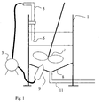
Figure 1 is a schematic view of a separation media slurry tank according to the invention. -
Figure 2 is a flow chart describing the steps of the method. -
Figure 1 is a schematic view of a separationmedia slurry tank 1 according to the invention. If media is to be fed to a column from a media storage container the media is first transferred from the storage container to a media tank according to the invention. This could be done by connecting a tube from the storage container to apump 3 provided in connection with the media slurry tank. Said pump is further connected to anadjustable pipe 5 that has anopen end 6 provided inside thetank 1. Saidadjustable pipe 5 is further described below. Hereby the media slurry can be pumped from the media storage container to the tank. Alternatively the media could be transferred from the storage container to the tank using another pump and some other tubes or pipes. - When the media has been transferred to the tank it immediately starts to sediment. An impeller 7 that is provided inside the tank can be started from the beginning and keep on stirring the media slurry the whole time until the media has been transferred to a column where it should be used for, for example chromatography, but according to the invention, as will be further described below, the impeller does not need to be ongoing the whole time. The impeller 7 is preferably designed as a coil in the height direction of the tank, this kind of impeller is also called a helical ribbon. Other designs such as a two- or three-bladed propeller or an impeller formed as an anchor are however also possible. In
Figure 1 a two-bladed propeller 7 is shown. Furthermore the impeller is suitably provided with its lowest end close to thebottom 8 of the tank. - According to the invention a
nozzle 9 is furthermore provided protruding into the tank from thebottom 8 of the tank. This nozzle is connected to thepump 3, which in turn is connected to theadjustable pipe 5 as described above. Theadjustable pipe 5 can be adjusted to have itsopen end 6 in a liquid phase provided above the sedimented media as soon as the media slurry is starting to sediment. According to the invention thepump 3 pumps liquid from the liquid phase, through theadjustable pipe 5 and further to thenozzle 9. The pump applies a pressure to the liquid in the nozzle and the nozzle is designed such that the liquid is introduced with some speed, such as spraying, into the sedimented media from thebottom 8 of the tank. This has the advantage that the sedimented media in the tank will start to re-suspend. Preferably the impeller is not started until the sedimented media has been sufficiently re-suspended by the spraying from the nozzle. Hereby it will be easier to start the impeller than it would have been if the impeller would have to start inside thick, sedimented media and the risk for damaging particles of the media is minimized. Furthermore the use of the liquid from the liquid phase of the sedimented media slurry for the spraying by the nozzle implies that no extra liquid need to be provided and the media slurry concentration can be kept constant. - When the media slurry has been stirred and mixed enough it can be transferred to a column through a
pipe 11 from the bottom of thetank 1. - The tank according to the invention can also be used when transferring media from a column to a storage container. It could be suitable to first transfer the media to the tank, suspend the media sufficiently according to what was previously described and then transfer the media slurry to the storage container.
- The method according to one embodiment of the invention where media slurry is transferred from a storage container to a column via the tank will now be further described with reference to the flowchart in
Figure 2 . The steps are described in order below. - S1: Media slurry is first transferred from the storage container to the tank according to the invention. This could be done by using a pump and a tube or pipe. Possibly a
pump 3 connected to the tank and theadjustable pipe 5 of the tank can be used for this transferring of media slurry from the storage container to the tank. As soon as the media slurry has entered the tank it starts to sediment - actually it is already sedimented to some degree since no stirring has been performed in the storage container, i.e. media will sediment at thebottom 8 of the tank and a liquid phase (possibly containing some particles also) will be built up over the sedimented media. - The method steps S2-S11 need not to be performed immediately after transferring of the media slurry to the tank. But when it is time for the transferring of the media slurry to the column the media slurry needs to be mixed into an homogenous media slurry and then the steps 52-S l will be performed.
- S2: The
adjustable pipe 5 is adjusted such that itsopen end 6 is in the liquid phase in the tank. - S3: The next step is to pump liquid from the liquid phase through the
adjustable pipe 5 by using thepump 3. - S5: The liquid is then transported through the
pump 3 to thenozzle 9. - S7: By applying a pressure to the
nozzle 9 from thepump 3 the liquid is sprayed out from thenozzle 9 from the bottom (8) of the tank into the sedimented media. - S9: When the sedimented media close to the
bottom 8 of the tank has been sufficiently re-suspended the impeller 7 is started. The impeller 7 is driven until a homogenous mixture of the media slurry is achieved. - S 11: When the media slurry is sufficiently mixed it is transferred to the column.
- If the method according to the invention should be applied for the invert transferring of media slurry, i.e. from column to storage container the same steps S1-S11 are followed with the only change that the storage container replaces the column and the column replaces the storage container.
Claims (7)
- A method for suspending separation media slurry in a tank, before transferring the separation media slurry to a column or a container, characterised by the steps of:- pumping liquid from an uppermost liquid phase being formed in the tank when the media slurry is sedimenting, said liquid possibly containing a small amount of media but is hereafter being called liquid;- transferring said liquid to a nozzle (9) protruding into said tank from the bottom (8) of the tank;- applying a pressure to said nozzle (9) such that said liquid is sprayed out from the nozzle (9) into the sedimented media in the tank and thereby the sedimented media starts to re-suspend;- starting an impeller (7) provided in the tank in order to stir said media slurry that already has started to re-suspend.
- A method according to claim 1, characterised by adjusting the height of an open end (6) of an adjustable pipe (5) provided inside the tank, the height being adjusted to the liquid phase of the media slurry having started to sediment, said adjustable pipe (5) being connected to said nozzle (9) through a pump (3).
- A tank adapted to be used for suspending separation media slurry before transferring the separation media slurry to a column or a container, said tank comprising:- an impeller (7) adapted to rotate in order to mix the media slurry,characterised in that said tank further comprises- a nozzle (9) provided protruding into the tank from the bottom (8) of the tank, and- an adjustable pipe (5) having an open end (6) positioned in the tank, said open end being possible to adjust in position, said nozzle (9) and said adjustable pipe (5) being adapted to be connected to a pump (3) which is adapted to pump liquid from the adjustable pipe (5) when said open end (6) of the adjustable pipe (5) has been positioned in an uppermost liquid phase provided in the tank when the media slurry has started to sediment and pump said liquid, possibly containing a small amount of media but hereafter being called liquid, through said nozzle (9) back into the tank from the bottom (8) of the tank in order to start to re-suspend media that has sedimented in the tank.
- A tank according to claim 3, characterised in that said impeller (7) is adapted to start after the sedimented media has started to re-suspend by the introducing of the liquid from the nozzle.
- A tank according to claim 3 or 4, characterised in that the impeller (7) is provided close to the bottom (8) of the tank.
- A tank according to any one of the claims 3-5, characterised in that the impeller (7) is designed as a coil in the height direction of the tank.
- A tank system comprising a tank according to any one of the claims 3-6 and a pump (3) connected to the adjustable pipe (5) and to the nozzle (9).
Applications Claiming Priority (2)
| Application Number | Priority Date | Filing Date | Title |
|---|---|---|---|
| SE0700014 | 2007-01-02 | ||
| PCT/SE2007/001125 WO2008082339A1 (en) | 2007-01-02 | 2007-12-18 | Separation media slurry tank |
Publications (3)
| Publication Number | Publication Date |
|---|---|
| EP2100136A1 EP2100136A1 (en) | 2009-09-16 |
| EP2100136A4 EP2100136A4 (en) | 2010-07-28 |
| EP2100136B1 true EP2100136B1 (en) | 2011-04-20 |
Family
ID=39588864
Family Applications (1)
| Application Number | Title | Priority Date | Filing Date |
|---|---|---|---|
| EP07852125A Active EP2100136B1 (en) | 2007-01-02 | 2007-12-18 | Tank for suspending separation media slurry |
Country Status (8)
| Country | Link |
|---|---|
| US (1) | US8092073B2 (en) |
| EP (1) | EP2100136B1 (en) |
| JP (1) | JP4975826B2 (en) |
| CN (1) | CN101573614B (en) |
| AT (1) | ATE506612T1 (en) |
| BR (1) | BRPI0719421B8 (en) |
| DE (1) | DE602007014099D1 (en) |
| WO (1) | WO2008082339A1 (en) |
Families Citing this family (11)
| Publication number | Priority date | Publication date | Assignee | Title |
|---|---|---|---|---|
| WO2009157853A1 (en) * | 2008-06-27 | 2009-12-30 | Ge Healthcare Bio-Sciences Ab | Separation media slurry tank |
| WO2010123594A2 (en) | 2009-01-15 | 2010-10-28 | Children's Medical Center Corporation | Device for filtration of fluids there through and accompanying method |
| US10252227B2 (en) | 2012-03-23 | 2019-04-09 | EKATO Ruehr- und Mischtecnik GmbH | System and method for starting up stirring machines in a sediment |
| JP6111330B2 (en) * | 2012-06-21 | 2017-04-05 | ジーイー・ヘルスケア・バイオサイエンス・アクチボラグ | Chromatography column nozzle |
| DK3052931T3 (en) * | 2013-09-30 | 2023-10-30 | Cytiva Sweden Ab | Slurry Transfer Procedure |
| CN103894285B (en) * | 2014-04-14 | 2016-03-16 | 何征徽 | A kind of magnetic iron ore dressing process |
| CN105148769A (en) * | 2015-10-19 | 2015-12-16 | 攀钢集团工程技术有限公司 | Mineral pulp stirring tank back-flushing device |
| US10881985B1 (en) * | 2016-12-08 | 2021-01-05 | Elemental Scientific, Inc. | System with reusable column with resin packing and unpacking procedures and sample analysis |
| US11253824B1 (en) * | 2018-03-29 | 2022-02-22 | Trusscore Inc. | Apparatus, methods, and systems for mixing and dispersing a dispersed phase in a medium |
| US10954929B2 (en) * | 2018-09-19 | 2021-03-23 | Mueller International, Llc | Material dispensing system with gas removal |
| CN112340256A (en) * | 2020-11-25 | 2021-02-09 | 大连海事大学 | Magnesium hydroxide slurry supply device and application thereof |
Family Cites Families (31)
| Publication number | Priority date | Publication date | Assignee | Title |
|---|---|---|---|---|
| US2365293A (en) * | 1941-04-25 | 1944-12-19 | Worthington Pump & Mach Corp | Water treating apparatus |
| US2516884A (en) * | 1948-12-08 | 1950-08-01 | George J Kyame | Method of and apparatus for preparation and distribution of sizing materials |
| US2900176A (en) * | 1957-04-10 | 1959-08-18 | Western Electric Co | Automatic fluid distribution system |
| DE1418567A1 (en) * | 1960-05-25 | 1968-10-10 | Ajinomoto Kk | Process for the continuous, optical separation of racemic mixtures of gultamic acid, glutamic acid hydrohalides and glutamates |
| US3202281A (en) * | 1964-10-01 | 1965-08-24 | Weston David | Method for the flotation of finely divided minerals |
| USRE27681E (en) * | 1970-09-24 | 1973-06-19 | Dry chemical feeder method and apparatus | |
| US3773302A (en) * | 1971-07-28 | 1973-11-20 | Eastman Kodak Co | Apparatus for making coupler dispersions |
| JPS54112379A (en) * | 1978-02-23 | 1979-09-03 | Mitsubishi Electric Corp | Liquid adsorber |
| CS212562B1 (en) * | 1979-09-11 | 1982-03-26 | Jiri Kratky | Reserve and homogenization container for the caoline suspensions |
| US4466082A (en) * | 1982-02-02 | 1984-08-14 | Foster Wheeler Energy Corporation | Apparatus for mixing and distributing solid particulate material |
| DE3342016C2 (en) * | 1983-11-22 | 1986-11-13 | VLT Gesellschaft für verfahrenstechnische Entwicklung mbH, 7000 Stuttgart | Device for mixing and settling liquids containing particles |
| JPS633260A (en) * | 1986-06-24 | 1988-01-08 | Kurita Water Ind Ltd | Chromatography device |
| US4732434A (en) * | 1986-09-29 | 1988-03-22 | Metalworks, Inc. | Horizontal file drawer interlock assembly |
| US4882098A (en) * | 1988-06-20 | 1989-11-21 | General Signal Corporation | Mass transfer mixing system especially for gas dispersion in liquids or liquid suspensions |
| IT1236950B (en) * | 1989-10-16 | 1993-05-07 | Minnesota Mining & Mfg | PROCEDURE FOR PRODUCING LIGHT-SENSITIVE SILVER HALIDE EMULSIONS. |
| JPH04323557A (en) | 1991-04-23 | 1992-11-12 | Hitachi Plant Eng & Constr Co Ltd | Device for filling column for chromatography |
| DE4117604A1 (en) * | 1991-05-29 | 1992-12-03 | Merck Patent Gmbh | METHOD AND DEVICE FOR FILLING CHROMATOGRAPHIC PILLARS |
| CA2102807C (en) * | 1992-01-10 | 2004-08-17 | Ioannis Scarpa | Cellulose chromatographic supports and method |
| US5334496A (en) * | 1992-09-17 | 1994-08-02 | Eastman Kodak Company | Process and apparatus for reproducible production of non-uniform product distributions |
| US5403088A (en) * | 1993-06-18 | 1995-04-04 | The Dow Chemical Company | Apparatus and method for the dispersion of minute bubbles in liquid materials for the production of polymer foams |
| JPH09143434A (en) * | 1995-11-27 | 1997-06-03 | Sekisui Chem Co Ltd | Applying method of hot melt adhesive |
| GB9812344D0 (en) | 1998-06-08 | 1998-08-05 | Euroflow Uk Ltd | Methods and apparatus for packing chromatography columns |
| GB2344543B (en) * | 1998-12-10 | 2002-11-27 | Millipore Corp | Chromatography column system and method of packing a chromatography system |
| JP2004505276A (en) * | 2000-07-28 | 2004-02-19 | ユーロフロー・(ユーケイ)・リミテッド | Method and apparatus for packing a chromatography column and chromatography column |
| US6443611B1 (en) * | 2000-12-15 | 2002-09-03 | Eastman Kodak Company | Apparatus for manufacturing photographic emulsions |
| DE10137613C2 (en) | 2001-08-01 | 2003-09-04 | Forschungszentrum Juelich Gmbh | Device and method for producing packed beds in a column |
| EP1348957A1 (en) * | 2002-03-27 | 2003-10-01 | Büchi Labortechnik AG | Device and process for filling a column with a filling material |
| DE10358400A1 (en) * | 2003-12-11 | 2005-07-07 | Linde-Kca-Dresden Gmbh | Biological treatment of suspension of, e.g. waste water, sewage sludge, in bioreactor by feeding horizontal jet(s) of fluid superimposing on vertical flow in bottom part of bioreactor |
| KR100571965B1 (en) * | 2004-09-25 | 2006-04-17 | 삼성전자주식회사 | Inkjet printing head and inkjet printer using the same |
| US7810674B2 (en) * | 2005-07-26 | 2010-10-12 | Millipore Corporation | Liquid dispensing system with enhanced mixing |
| US8931948B2 (en) * | 2008-10-01 | 2015-01-13 | Bp Corporation North America Inc. | Process and apparatus for mixing a fluid within a vessel |
-
2007
- 2007-12-18 JP JP2009543982A patent/JP4975826B2/en active Active
- 2007-12-18 DE DE602007014099T patent/DE602007014099D1/de active Active
- 2007-12-18 US US12/517,447 patent/US8092073B2/en active Active
- 2007-12-18 EP EP07852125A patent/EP2100136B1/en active Active
- 2007-12-18 WO PCT/SE2007/001125 patent/WO2008082339A1/en active Application Filing
- 2007-12-18 CN CN2007800491514A patent/CN101573614B/en active Active
- 2007-12-18 BR BRPI0719421A patent/BRPI0719421B8/en active IP Right Grant
- 2007-12-18 AT AT07852125T patent/ATE506612T1/en active
Also Published As
| Publication number | Publication date |
|---|---|
| BRPI0719421B8 (en) | 2022-07-05 |
| CN101573614A (en) | 2009-11-04 |
| ATE506612T1 (en) | 2011-05-15 |
| CN101573614B (en) | 2013-07-10 |
| EP2100136A1 (en) | 2009-09-16 |
| BRPI0719421B1 (en) | 2018-07-17 |
| BRPI0719421A2 (en) | 2014-02-11 |
| WO2008082339A1 (en) | 2008-07-10 |
| JP4975826B2 (en) | 2012-07-11 |
| DE602007014099D1 (en) | 2011-06-01 |
| US8092073B2 (en) | 2012-01-10 |
| EP2100136A4 (en) | 2010-07-28 |
| JP2010515049A (en) | 2010-05-06 |
| US20100044323A1 (en) | 2010-02-25 |
Similar Documents
| Publication | Publication Date | Title |
|---|---|---|
| EP2100136B1 (en) | Tank for suspending separation media slurry | |
| EP2297570B1 (en) | Separation media slurry tank | |
| US20080197605A1 (en) | Method for Constructing and Treating Subterranean Formations | |
| WO2000001981A1 (en) | Storage and transport of gas hydrates as a slurry suspension under metastable conditions | |
| CN106113268A (en) | A kind of pressure break ship sediment transport hybrid system and sediment transport method | |
| CN115319918A (en) | Structural gap grouting equipment for constructional engineering and grouting process thereof | |
| US20130233393A1 (en) | Method and Apparatus for Mixing, Transporting, Storing, and Transferring Thixotropic Fluids in One Container | |
| CN205330642U (en) | On --spot device that pours into into of microorganism displacement of reservoir oil solid activator | |
| CN107670579A (en) | Can the fracturing fluid of auto feed mix sizing device | |
| GB2566551A (en) | Subsea storage of crude oil | |
| EP1726356A1 (en) | Slurry discharging method | |
| EP3996834B1 (en) | Method and installation for homogenizing a shear thinning fluid contained in a cylindrical tank | |
| CN217676790U (en) | Glue split-charging pressure plate for 55 gallon barrel | |
| WO2023045033A1 (en) | Fracturing operation vessel | |
| RU2807855C1 (en) | Underwater reservoir for liquid storage and method for underwater liquid storage | |
| CN101354519A (en) | Processing method capable of making electric conduction roller obtain uniform coating and dip coating apparatus | |
| Weinstein et al. | Dry-polymer blending eliminates need for hydrocarbon carrier fluids | |
| CN105579363B (en) | Flexible container is used for the purposes for storing liquid | |
| CN115434682A (en) | Invariable sand carrying liquid and sand proportioning device for fracturing | |
| CN203316105U (en) | Feeding stabilizing device of ejection liquefying system | |
| NO20171505A1 (en) | Subsea storage of crude oil |
Legal Events
| Date | Code | Title | Description |
|---|---|---|---|
| PUAI | Public reference made under article 153(3) epc to a published international application that has entered the european phase |
Free format text: ORIGINAL CODE: 0009012 |
|
| 17P | Request for examination filed |
Effective date: 20090511 |
|
| AK | Designated contracting states |
Kind code of ref document: A1 Designated state(s): AT BE BG CH CY CZ DE DK EE ES FI FR GB GR HU IE IS IT LI LT LU LV MC MT NL PL PT RO SE SI SK TR |
|
| DAX | Request for extension of the european patent (deleted) | ||
| A4 | Supplementary search report drawn up and despatched |
Effective date: 20100630 |
|
| RIC1 | Information provided on ipc code assigned before grant |
Ipc: G01N 30/56 20060101AFI20080721BHEP Ipc: B01D 15/08 20060101ALI20100624BHEP Ipc: B01D 15/20 20060101ALI20100624BHEP Ipc: G01N 30/50 20060101ALI20100624BHEP |
|
| 17Q | First examination report despatched |
Effective date: 20100713 |
|
| GRAP | Despatch of communication of intention to grant a patent |
Free format text: ORIGINAL CODE: EPIDOSNIGR1 |
|
| RIC1 | Information provided on ipc code assigned before grant |
Ipc: B01D 15/20 20060101ALI20101117BHEP Ipc: G01N 30/56 20060101AFI20101117BHEP Ipc: B01D 15/08 20060101ALI20101117BHEP Ipc: G01N 30/50 20060101ALI20101117BHEP |
|
| RTI1 | Title (correction) |
Free format text: TANK FOR SUSPENDING SEPARATION MEDIA SLURRY |
|
| GRAS | Grant fee paid |
Free format text: ORIGINAL CODE: EPIDOSNIGR3 |
|
| GRAA | (expected) grant |
Free format text: ORIGINAL CODE: 0009210 |
|
| AK | Designated contracting states |
Kind code of ref document: B1 Designated state(s): AT BE BG CH CY CZ DE DK EE ES FI FR GB GR HU IE IS IT LI LT LU LV MC MT NL PL PT RO SE SI SK TR |
|
| REG | Reference to a national code |
Ref country code: GB Ref legal event code: FG4D |
|
| REG | Reference to a national code |
Ref country code: CH Ref legal event code: EP |
|
| REG | Reference to a national code |
Ref country code: IE Ref legal event code: FG4D |
|
| REF | Corresponds to: |
Ref document number: 602007014099 Country of ref document: DE Date of ref document: 20110601 Kind code of ref document: P |
|
| REG | Reference to a national code |
Ref country code: DE Ref legal event code: R096 Ref document number: 602007014099 Country of ref document: DE Effective date: 20110601 |
|
| REG | Reference to a national code |
Ref country code: CH Ref legal event code: NV Representative=s name: ISLER & PEDRAZZINI AG |
|
| REG | Reference to a national code |
Ref country code: NL Ref legal event code: T3 |
|
| REG | Reference to a national code |
Ref country code: SE Ref legal event code: TRGR |
|
| LTIE | Lt: invalidation of european patent or patent extension |
Effective date: 20110420 |
|
| PG25 | Lapsed in a contracting state [announced via postgrant information from national office to epo] |
Ref country code: PT Free format text: LAPSE BECAUSE OF FAILURE TO SUBMIT A TRANSLATION OF THE DESCRIPTION OR TO PAY THE FEE WITHIN THE PRESCRIBED TIME-LIMIT Effective date: 20110822 Ref country code: LT Free format text: LAPSE BECAUSE OF FAILURE TO SUBMIT A TRANSLATION OF THE DESCRIPTION OR TO PAY THE FEE WITHIN THE PRESCRIBED TIME-LIMIT Effective date: 20110420 |
|
| PG25 | Lapsed in a contracting state [announced via postgrant information from national office to epo] |
Ref country code: SI Free format text: LAPSE BECAUSE OF FAILURE TO SUBMIT A TRANSLATION OF THE DESCRIPTION OR TO PAY THE FEE WITHIN THE PRESCRIBED TIME-LIMIT Effective date: 20110420 Ref country code: FI Free format text: LAPSE BECAUSE OF FAILURE TO SUBMIT A TRANSLATION OF THE DESCRIPTION OR TO PAY THE FEE WITHIN THE PRESCRIBED TIME-LIMIT Effective date: 20110420 Ref country code: LV Free format text: LAPSE BECAUSE OF FAILURE TO SUBMIT A TRANSLATION OF THE DESCRIPTION OR TO PAY THE FEE WITHIN THE PRESCRIBED TIME-LIMIT Effective date: 20110420 Ref country code: ES Free format text: LAPSE BECAUSE OF FAILURE TO SUBMIT A TRANSLATION OF THE DESCRIPTION OR TO PAY THE FEE WITHIN THE PRESCRIBED TIME-LIMIT Effective date: 20110731 Ref country code: CY Free format text: LAPSE BECAUSE OF FAILURE TO SUBMIT A TRANSLATION OF THE DESCRIPTION OR TO PAY THE FEE WITHIN THE PRESCRIBED TIME-LIMIT Effective date: 20110420 Ref country code: IS Free format text: LAPSE BECAUSE OF FAILURE TO SUBMIT A TRANSLATION OF THE DESCRIPTION OR TO PAY THE FEE WITHIN THE PRESCRIBED TIME-LIMIT Effective date: 20110820 Ref country code: GR Free format text: LAPSE BECAUSE OF FAILURE TO SUBMIT A TRANSLATION OF THE DESCRIPTION OR TO PAY THE FEE WITHIN THE PRESCRIBED TIME-LIMIT Effective date: 20110721 |
|
| PG25 | Lapsed in a contracting state [announced via postgrant information from national office to epo] |
Ref country code: CZ Free format text: LAPSE BECAUSE OF FAILURE TO SUBMIT A TRANSLATION OF THE DESCRIPTION OR TO PAY THE FEE WITHIN THE PRESCRIBED TIME-LIMIT Effective date: 20110420 Ref country code: EE Free format text: LAPSE BECAUSE OF FAILURE TO SUBMIT A TRANSLATION OF THE DESCRIPTION OR TO PAY THE FEE WITHIN THE PRESCRIBED TIME-LIMIT Effective date: 20110420 |
|
| PGFP | Annual fee paid to national office [announced via postgrant information from national office to epo] |
Ref country code: SE Payment date: 20111229 Year of fee payment: 5 |
|
| PLBE | No opposition filed within time limit |
Free format text: ORIGINAL CODE: 0009261 |
|
| STAA | Information on the status of an ep patent application or granted ep patent |
Free format text: STATUS: NO OPPOSITION FILED WITHIN TIME LIMIT |
|
| PG25 | Lapsed in a contracting state [announced via postgrant information from national office to epo] |
Ref country code: SK Free format text: LAPSE BECAUSE OF FAILURE TO SUBMIT A TRANSLATION OF THE DESCRIPTION OR TO PAY THE FEE WITHIN THE PRESCRIBED TIME-LIMIT Effective date: 20110420 Ref country code: RO Free format text: LAPSE BECAUSE OF FAILURE TO SUBMIT A TRANSLATION OF THE DESCRIPTION OR TO PAY THE FEE WITHIN THE PRESCRIBED TIME-LIMIT Effective date: 20110420 Ref country code: PL Free format text: LAPSE BECAUSE OF FAILURE TO SUBMIT A TRANSLATION OF THE DESCRIPTION OR TO PAY THE FEE WITHIN THE PRESCRIBED TIME-LIMIT Effective date: 20110420 Ref country code: DK Free format text: LAPSE BECAUSE OF FAILURE TO SUBMIT A TRANSLATION OF THE DESCRIPTION OR TO PAY THE FEE WITHIN THE PRESCRIBED TIME-LIMIT Effective date: 20110420 |
|
| 26N | No opposition filed |
Effective date: 20120123 |
|
| PGFP | Annual fee paid to national office [announced via postgrant information from national office to epo] |
Ref country code: BE Payment date: 20111227 Year of fee payment: 5 |
|
| REG | Reference to a national code |
Ref country code: DE Ref legal event code: R097 Ref document number: 602007014099 Country of ref document: DE Effective date: 20120123 |
|
| PG25 | Lapsed in a contracting state [announced via postgrant information from national office to epo] |
Ref country code: MC Free format text: LAPSE BECAUSE OF NON-PAYMENT OF DUE FEES Effective date: 20111231 |
|
| PGFP | Annual fee paid to national office [announced via postgrant information from national office to epo] |
Ref country code: NL Payment date: 20120103 Year of fee payment: 5 |
|
| REG | Reference to a national code |
Ref country code: IE Ref legal event code: MM4A |
|
| PG25 | Lapsed in a contracting state [announced via postgrant information from national office to epo] |
Ref country code: IE Free format text: LAPSE BECAUSE OF NON-PAYMENT OF DUE FEES Effective date: 20111218 |
|
| PG25 | Lapsed in a contracting state [announced via postgrant information from national office to epo] |
Ref country code: MT Free format text: LAPSE BECAUSE OF FAILURE TO SUBMIT A TRANSLATION OF THE DESCRIPTION OR TO PAY THE FEE WITHIN THE PRESCRIBED TIME-LIMIT Effective date: 20110420 |
|
| PGFP | Annual fee paid to national office [announced via postgrant information from national office to epo] |
Ref country code: IT Payment date: 20121218 Year of fee payment: 6 |
|
| PGFP | Annual fee paid to national office [announced via postgrant information from national office to epo] |
Ref country code: AT Payment date: 20121204 Year of fee payment: 6 |
|
| PG25 | Lapsed in a contracting state [announced via postgrant information from national office to epo] |
Ref country code: LU Free format text: LAPSE BECAUSE OF NON-PAYMENT OF DUE FEES Effective date: 20111218 |
|
| PG25 | Lapsed in a contracting state [announced via postgrant information from national office to epo] |
Ref country code: BG Free format text: LAPSE BECAUSE OF FAILURE TO SUBMIT A TRANSLATION OF THE DESCRIPTION OR TO PAY THE FEE WITHIN THE PRESCRIBED TIME-LIMIT Effective date: 20110720 |
|
| BERE | Be: lapsed |
Owner name: GE HEALTHCARE BIO-SCIENCES A.B. Effective date: 20121231 |
|
| REG | Reference to a national code |
Ref country code: NL Ref legal event code: V1 Effective date: 20130701 |
|
| PG25 | Lapsed in a contracting state [announced via postgrant information from national office to epo] |
Ref country code: SE Free format text: LAPSE BECAUSE OF NON-PAYMENT OF DUE FEES Effective date: 20121219 |
|
| PG25 | Lapsed in a contracting state [announced via postgrant information from national office to epo] |
Ref country code: BE Free format text: LAPSE BECAUSE OF NON-PAYMENT OF DUE FEES Effective date: 20121231 Ref country code: TR Free format text: LAPSE BECAUSE OF FAILURE TO SUBMIT A TRANSLATION OF THE DESCRIPTION OR TO PAY THE FEE WITHIN THE PRESCRIBED TIME-LIMIT Effective date: 20110420 |
|
| PG25 | Lapsed in a contracting state [announced via postgrant information from national office to epo] |
Ref country code: NL Free format text: LAPSE BECAUSE OF NON-PAYMENT OF DUE FEES Effective date: 20130701 Ref country code: HU Free format text: LAPSE BECAUSE OF FAILURE TO SUBMIT A TRANSLATION OF THE DESCRIPTION OR TO PAY THE FEE WITHIN THE PRESCRIBED TIME-LIMIT Effective date: 20110420 |
|
| REG | Reference to a national code |
Ref country code: AT Ref legal event code: MM01 Ref document number: 506612 Country of ref document: AT Kind code of ref document: T Effective date: 20131218 |
|
| PG25 | Lapsed in a contracting state [announced via postgrant information from national office to epo] |
Ref country code: AT Free format text: LAPSE BECAUSE OF NON-PAYMENT OF DUE FEES Effective date: 20131218 |
|
| PG25 | Lapsed in a contracting state [announced via postgrant information from national office to epo] |
Ref country code: IT Free format text: LAPSE BECAUSE OF NON-PAYMENT OF DUE FEES Effective date: 20131231 |
|
| REG | Reference to a national code |
Ref country code: FR Ref legal event code: PLFP Year of fee payment: 9 |
|
| PG25 | Lapsed in a contracting state [announced via postgrant information from national office to epo] |
Ref country code: IT Free format text: LAPSE BECAUSE OF NON-PAYMENT OF DUE FEES Effective date: 20131218 |
|
| REG | Reference to a national code |
Ref country code: FR Ref legal event code: PLFP Year of fee payment: 10 |
|
| REG | Reference to a national code |
Ref country code: DE Ref legal event code: R082 Ref document number: 602007014099 Country of ref document: DE |
|
| REG | Reference to a national code |
Ref country code: FR Ref legal event code: PLFP Year of fee payment: 11 |
|
| REG | Reference to a national code |
Ref country code: DE Ref legal event code: R081 Ref document number: 602007014099 Country of ref document: DE Owner name: CYTIVA SWEDEN AB, SE Free format text: FORMER OWNER: GE HEALTHCARE BIO-SCIENCES AB, UPPSALA, SE |
|
| REG | Reference to a national code |
Ref country code: CH Ref legal event code: NV Representative=s name: BOVARD SA NEUCHATEL CONSEILS EN PROPRIETE INTE, CH Ref country code: CH Ref legal event code: PFA Owner name: CYTIVA SWEDEN AB, SE Free format text: FORMER OWNER: GE HEALTHCARE BIO-SCIENCES AB, SE |
|
| PGFP | Annual fee paid to national office [announced via postgrant information from national office to epo] |
Ref country code: CH Payment date: 20230101 Year of fee payment: 16 |
|
| P01 | Opt-out of the competence of the unified patent court (upc) registered |
Effective date: 20230526 |
|
| PGFP | Annual fee paid to national office [announced via postgrant information from national office to epo] |
Ref country code: GB Payment date: 20231026 Year of fee payment: 17 |
|
| PGFP | Annual fee paid to national office [announced via postgrant information from national office to epo] |
Ref country code: FR Payment date: 20231009 Year of fee payment: 17 Ref country code: DE Payment date: 20231024 Year of fee payment: 17 |