EP2099229A1 - Image processing method and apparatus - Google Patents
Image processing method and apparatus Download PDFInfo
- Publication number
- EP2099229A1 EP2099229A1 EP09154262A EP09154262A EP2099229A1 EP 2099229 A1 EP2099229 A1 EP 2099229A1 EP 09154262 A EP09154262 A EP 09154262A EP 09154262 A EP09154262 A EP 09154262A EP 2099229 A1 EP2099229 A1 EP 2099229A1
- Authority
- EP
- European Patent Office
- Prior art keywords
- chromatic aberration
- magnification chromatic
- image
- color
- applying
- Prior art date
- Legal status (The legal status is an assumption and is not a legal conclusion. Google has not performed a legal analysis and makes no representation as to the accuracy of the status listed.)
- Granted
Links
Images



Classifications
-
- H—ELECTRICITY
- H04—ELECTRIC COMMUNICATION TECHNIQUE
- H04N—PICTORIAL COMMUNICATION, e.g. TELEVISION
- H04N5/00—Details of television systems
- H04N5/14—Picture signal circuitry for video frequency region
- H04N5/20—Circuitry for controlling amplitude response
-
- H—ELECTRICITY
- H04—ELECTRIC COMMUNICATION TECHNIQUE
- H04N—PICTORIAL COMMUNICATION, e.g. TELEVISION
- H04N25/00—Circuitry of solid-state image sensors [SSIS]; Control thereof
- H04N25/60—Noise processing, e.g. detecting, correcting, reducing or removing noise
- H04N25/61—Noise processing, e.g. detecting, correcting, reducing or removing noise the noise originating only from the lens unit, e.g. flare, shading, vignetting or "cos4"
-
- H—ELECTRICITY
- H04—ELECTRIC COMMUNICATION TECHNIQUE
- H04N—PICTORIAL COMMUNICATION, e.g. TELEVISION
- H04N25/00—Circuitry of solid-state image sensors [SSIS]; Control thereof
- H04N25/60—Noise processing, e.g. detecting, correcting, reducing or removing noise
- H04N25/61—Noise processing, e.g. detecting, correcting, reducing or removing noise the noise originating only from the lens unit, e.g. flare, shading, vignetting or "cos4"
- H04N25/611—Correction of chromatic aberration
-
- H—ELECTRICITY
- H04—ELECTRIC COMMUNICATION TECHNIQUE
- H04N—PICTORIAL COMMUNICATION, e.g. TELEVISION
- H04N25/00—Circuitry of solid-state image sensors [SSIS]; Control thereof
- H04N25/60—Noise processing, e.g. detecting, correcting, reducing or removing noise
- H04N25/61—Noise processing, e.g. detecting, correcting, reducing or removing noise the noise originating only from the lens unit, e.g. flare, shading, vignetting or "cos4"
- H04N25/615—Noise processing, e.g. detecting, correcting, reducing or removing noise the noise originating only from the lens unit, e.g. flare, shading, vignetting or "cos4" involving a transfer function modelling the optical system, e.g. optical transfer function [OTF], phase transfer function [PhTF] or modulation transfer function [MTF]
- H04N25/6153—Noise processing, e.g. detecting, correcting, reducing or removing noise the noise originating only from the lens unit, e.g. flare, shading, vignetting or "cos4" involving a transfer function modelling the optical system, e.g. optical transfer function [OTF], phase transfer function [PhTF] or modulation transfer function [MTF] for colour signals
-
- H—ELECTRICITY
- H04—ELECTRIC COMMUNICATION TECHNIQUE
- H04N—PICTORIAL COMMUNICATION, e.g. TELEVISION
- H04N9/00—Details of colour television systems
- H04N9/64—Circuits for processing colour signals
- H04N9/646—Circuits for processing colour signals for image enhancement, e.g. vertical detail restoration, cross-colour elimination, contour correction, chrominance trapping filters
Definitions
- the present invention relates to an image processing method and an image processing apparatus, and in particular to an image processing method and an image processing apparatus capable of processing images obtained by a wide-angle optical system correcting a large magnification chromatic aberration.
- 2006-345054 describes a method of simultaneously correcting both of the magnification chromatic aberration and the distortion by independently converting a coordinate of each of RGB signals obtained by an imaging element, such as a CCD, a CMOS sensor, etc., per component color of RGB at a later step. Also described is a method of only correcting the distortion by collectively converting respective component colors of RGB at once neglecting the magnification chromatic aberration.
- a high band emphasis filter (e.g. MTF correction) is conventionally used for the purpose of correcting deterioration of resolution caused by an optical system, such as a lens, etc.
- the Japanese Patent Application Laid Open No. 2006-345054 discusses a method of applying high band emphasis filtering to each of RGB signals per RGB after correcting a magnification chromatic aberration and a distortion of RGB signals. Also discussed there is that RGB signals are separated into brightness and color signals and aberration correction is executed, and then high band emphasis filtering is applied to the brightness signal and the like.
- the former method introduces a large-scale circuit due to combination of a high band emphasis filter and an aberration correction circuit per each of RGB with poor image quality due to increase of color noise.
- the latter method can avoid increase of color noise indeed, but disables correction of the magnification chromatic aberration that is generally enabled by independently correcting an aberration per each of RGB for the purpose of coordinate conversion of brightness and color signals other than RGB signals.
- the present invention has been made in view of the above noted and another problems and one object of the present invention is to provide a new and noble image processing method.
- Such a new and noble image processing method comprises the steps of applying a magnification chromatic aberration correction processing to an image, applying a separation processing to the image for separating the image into a brightness signal and a color signal after the step of applying the magnification chromatic aberration correction, and applying a high band emphasis processing only to the brightness signal after the step of applying the separation processing.
- the method further comprises the step of combining the brightness signal subjected to the high band emphasis processing with the color signal.
- the method further comprises the step of smoothing the color signal in parallel to the step of applying the high band emphasis processing to the brightness signal. In yet another aspect, the method further comprises the step of changing an intensity of the smoothing the color signal in accordance with a luminance of a photographic subject. In yet another aspect, the step of smoothing the color signal is executed only when the luminance decreases to a prescribed dark level. In yet another aspect, the magnification chromatic aberration is corrected by partially converting coordinates of multi color components in the step of executing the magnification chromatic aberration correction processing.
- a coordinate conversion amount of a first color component is obtained with reference to a coordinate of a reference color component, and a coordinate conversion amount of a second color component is calculated in accordance with the coordinate conversion amount of the first color component.
- the distortion correction processing is executed separately from the magnification chromatic aberration correction processing.
- the distortion correction processing is executed in the later step of the high band emphasis processing.
- the distortion correction processing is executed simultaneously with the magnification chromatic aberration correction processing.
- an image processing method and apparatus capable of correcting magnification chromatic aberration and MTF can be provided downsizing a circuit while suppressing deterioration of image quality
- FIG. 1 an image processing apparatus is described, in which color components of either addition three primitive colors of Red, Green, and Blue or subtraction three primitive colors of Yellow, Magenta, and Cyan is employed.
- the image processing apparatus includes a magnification chromatic aberration correction device 100 and a MTF correction device 200.
- the MTF correction device 200 includes a color/brightness signal separation device 210, a high band emphasis filter (FIR filter) 220, and a color/brightness signal combination device 240.
- FIR filter high band emphasis filter
- the magnification chromatic aberration correction device 100 receives RGB image data having a magnification chromatic aberration, which is obtained by photographing with a wide angle optical system having a large magnification chromatic aberration and is read by an imaging element, such as a CCD, a CMOS sensor, etc.
- the magnification chromatic aberration correction device 100 then converts a coordinate of RGB image data separately using a prescribed polynomial or the like and outputs RGB image data having been subjected to the magnification chromatic aberration correction.
- the magnification chromatic aberration correction device 100 mentioned later in detail can employ a memory of a small capacity and low latency or a memory such as a SRAM having plural ports and low capacity.
- the MTF correction device 200 receives and separates RGB pixel data subjected to the magnification chromatic aberration correction to a brightness signal and a color signal using the color/brightness signal separation device 210.
- the MTF correction device 200 applies high band emphasis processing (e.g. MTF correction) to the brightness signal using the FIR filter 220 and combines the brightness signal subjected to the high band emphasis and the color signal in a color/brightness signal-combining device 240.
- the MTF correction device 200 then outputs RGB pixel data.
- the FIR filter 220 includes a (5x5) filter and receives and applies the MTF correction only to the brightness signal Y among the brightness signal Y and the color signals Cr and Cb. By only applying the high band emphasis filtering ((MTF correction) to the Y signal, a high quality image is obtained suppressing color noise.
- An exemplary coefficient of the FIR filter is illustrated in FIG. 2 .
- the magnification chromatic aberration correction of the RGB can be independently performed appropriately, and the MTF correction of the high band emphasis filtering can only be applied to the brightness signal. As a result, a circuit can be maintained compact while suppressing color noise.
- the MTF correction device 200 only includes the color brightness signal device 210 and the FIR filter 220 excluding the color brightness signal-combining device 240.
- the configuration of FIG. 3 is simply employed.
- the magnification chromatic aberration correction device 100 can be replaced with a magnification chromatic aberration/distortion correction device that independently converts coordinates of RGB image data per component color of RGB and simultaneously corrects the magnification chromatic aberration and distortion. Such replacement can be achieved only by changing parameter of a correction formula (e.g. a coordinate conversion formula).
- a FIR filter 230 is added to the configuration of FIG. 3 to apply smoothing filtering to a color signal in addition to MTF correction in order to reduce color noise.
- the magnification chromatic aberration correction device 100 can be replaced with a magnification chromatic aberration/distortion correction device.
- the FIR filter 230 for the color signal can be substituted by not only a filter that reduces noise but also that capable of improving color saturation by simply adjusting a gain. To improve sensitivity of an imaging element when used for a dark photographing subject or in dark environment, a gain of a signal read from the imaging element is raised. However, in such a situation, the noise increases.
- the FIR filter 230 for noise reduction use for color information is used when the gain is high, and accordingly lightness of the photographing subject decreases (i.e., dark). Otherwise, a coefficient of the FIR filter 230 is changed to change smoothing intensity in accordance with the gain (i.e., the lightness of the photographing subject).
- the lightness of the photographing subject can be directly read by a lightness sensor provided separately. Further, the coefficient of the FIR filter 230 can be changed by selectively employing one of separately equipped FIR filters having a different coefficient from each other in accordance with the gain (i.e., the lightness).
- FIG. 5 illustrates another modification in which a distortion correction device 300 is newly added to the configuration of FIG. 1 in the subsequent step of the MTF correction device 200.
- the distortion correction device 300 receives RGB image data subjected to magnification chromatic aberration and MTF corrections and commonly applies the coordinate conversion processing to RGB using a prescribed polynomial expression or the like, and outputs RGB image data subjected to the distortion correction.
- the magnification chromatic aberration of RGB is different from each other, but the distortion of those are the same.
- the distortion is significantly larger than the magnification chromatic aberration.
- a memory such as a SRAM of a small capacity and low latency, that of a low capacity and multi port, etc., can be used for converting a coordinate for magnification chromatic aberration correction.
- a large capacity and high latency memory such as a DRAM, etc., having a common single port can be used to convert a coordinate for distortion correction.
- the entire apparatus can be manufactured at low cost.
- an interpolation error created by the coordinate conversion executed for the distortion correction is amplified and thereby affecting image quality.
- the interpolation error can be reduced by an interpolator that executes interpolation for pixels during the coordinate conversion.
- affection of an interpolation error to image quality is small in the coordinate conversion for the magnification chromatic aberration correction.
- the interpolation error caused by the distortion correction is not amplified by the MTF correction. Beside, since the magnification chromatic aberration correction and the MTF correction can be executed in this order, the finest image quality can be obtained.
- FIG. 6 illustrates still another modification in which a distortion correction device 300 is newly provided in a subsequent stage of the MTF correction device 200 in addition to the configuration of FIG. 3 .
- the distortion correction device 300 executes distortion correction by coordinate conversion for each of a brightness signal and a color signal.
- FIG. 6 When brightness and color signals excluding RGB signal are preferably outputted to a subsequent stage, the configuration of FIG. 6 is simply preferably employed. Further, a distortion correction device 300 as shown in FIG. 6 can be employed in addition to the configuration of FIG. 4 .
- magnification chromatic aberration correction device 100 and the distortion correction device 300 are described in more detail starting with their principle.
- image data (pixel data) located at a position (pixel) 1 on the right upper screen deviates from an original position due to the distortion, and further differently deviates from each other therefrom due to the magnification chromatic aberration among the respective color components of RGB, thereby positioning at 2(R), 3(G), and 4(B), respectively.
- the magnification chromatic aberration and the distortion can be corrected by copying image data of RGB color components positioning at 2(R), 3(G), and 4(B), respectively, onto a position 1 (pixel) serving as an original position. That is, the correction is achieved by converting the coordinate.
- the positions 2, 3, and 4 serve as coordinate conversion coordinate origins
- the position 1 serves as a coordinate conversion destination.
- FIG. 8 typically illustrates a method of simultaneously correcting the distortion and the magnification chromatic aberration.
- the magnification chromatic aberration and the distortion can be simultaneously corrected by copying image data of RGB components positioning at 2(R), 3(G), and 4(B) (pixel), respectively, onto a position 1 (pixel) serving as an original position of those. That is, the correction is simultaneously executed by converting the coordinate.
- a method necessitates a large capacity memory of either low latency or a multi port per RGB color component. For example, a six line high-speed memory is needed to convert a coordinate per component color (RGB) in this example.
- FIG. 9 typically illustrates a method of independently correcting a distortion and a magnification chromatic aberration.
- the magnification chromatic aberration of the respective RGB color components is different from each other but is small. Whereas the distortion is large but is the same.
- a coordinate of image data of each of the respective RGB color components is initially converted (coordinates of color components of RB are converted and copied onto a position of G component in the later described embodiment) and the magnification chromatic aberration is corrected. Then, the coordinates of RGB image data subjected to the magnification chromatic aberration correction are converted at once so that the distortion is corrected.
- coordinate correction use memories can be divided into two.
- a small capacity and high-speed (low latency or multi port) memory is provided for RGB capable of correcting the magnification chromatic aberration, while a large capacity and low speed (high latency or single port) memory is provided and commonly used by RGB for correcting the distortion. Accordingly, the cost can be reduced as a whole.
- FIG. 9A typically illustrates correction of the magnification chromatic aberration. Coordinates of image data of the respective RB color components existing at the positions (pixel) 2(R) and 4(B) are converted and are copied onto a position (pixels) 3(G) of the G component, thereby the magnification chromatic aberration is corrected.
- FIG. 9B typically illustrates correction of the distortion. Coordinates of image data of the respective RGB color components existing at the position 3 (pixel) having been subjected to magnification chromatic aberration correction are converted in a block, and are copied onto the position (pixel) 1 serving as an original position, thereby the distortion is corrected.
- the high-speed memory for the magnification chromatic aberration correction use is preferably a three-line memory handling respective RGB.
- a five-line memory is needed for distortion correction and a low speed memory is employed while a one port is commonly used by the RGB.
- the cost can be reduced as a whole in comparison with FIG. 8 .
- the distortion represents deformation of a lens in relation to a projection system, in which a looked down image is obtained from above a camera or that is partially expanded and displayed.
- FIG. 10 An exemplary configuration of a magnification chromatic aberration correction device 100 is illustrated in FIG. 10 .
- 110 denotes a magnification chromatic aberration correction use coordinate conversion memory (a line buffer), and respective 110(R), 110(G), and 110(B) correspond to respective RGB color components.
- 120 denotes a magnification chromatic aberration correction coordinate conversion calculation section that calculates a conversion coordinate for magnification chromatic aberration correction per each of the RGB in accordance with a prescribed coordinate conversion formula.
- 130 denotes a coordinate conversion coefficient table that stores coefficients used by the prescribed coordinate conversion formula.
- each of the coordinate conversion memories 142(R) to 142(B) can include a SRAM having twenty lines.
- a size in the direction X is determined by resolution, and it is 640 dots when the resolution is VGA (640 x 480).
- Color depth is RGB eight bit, so that writing and reading operations to and from respective coordinate conversion memories 142(R) to 142(B) are executed in a unit of eight bits.
- each of the magnification chromatic aberration correction use coordinate conversion memories (line buffers) 110(R) to 110(B) has a small capacity
- a memory region having twenty lines is preferably maintained using the three port SRAM provided in an image-processing chip.
- a memory having one port can be used as a three-port memory by timesharing.
- Respective RGB image data subjected to magnification chromatic aberration correction are sequentially written into the coordinate conversion memories 110(R) to 110(B) from the leading line thereof in accordance with a coordinate value (x, y).
- the coordinate conversion memories 110(R) to 110(B) are sequentially stored with the RGB image data having maximum twenty lines needed for magnification chromatic aberration correction coordinate conversion, respectively.
- the coordinate value (x, y) represents a position for reading a photograph image of one frame.
- the coordinate conversion memories 110(R) to 110(B) are the twenty line buffers and a writing line varies in a cyclic, the coordinate value (x, y) cannot be used as is as a writing address of each of the coordinate conversion memories 110(R) to 110(B). For this reason, the coordinate value (x, y) needs to be converted into an actual address of each of the coordinate conversion memories 110(R) to 110(B).
- a configuration therefor is not shown in FIG. 10 . It is the same in a relation between a coordinate value (x, y) subjected to conversion in a reading operation as mentioned later and a reading address of each of the coordinate conversion memories 110(R) to 110(B).
- the magnification chromatic aberration correction coordinate conversion calculation section 120 receives the coordinate value (x, y) serving as a coordinate conversion destination coordinate and calculates a conversion coordinate for magnification chromatic aberration correction per each of the RGB.
- the aberration correction coordinate conversion calculation section 120 then outputs a coordinate (X, Y) serving as a coordinate conversion origin coordinate per each of the RGB.
- magnification chromatic aberration correction coordinate conversion calculation section 120 outputs the coordinate value (x, y) as is as the coordinate value (X, Y) for the G color component.
- the magnification chromatic aberration correction coordinate conversion calculation section 120 converts the coordinate value (x, y) into the coordinate value (X, Y) using a prescribed coordinate conversion formula and outputs the same for the RB color components.
- the magnification chromatic aberration correction coordinate conversion calculation section 120 repeats this per coordinate value (x, y).
- Such a coordinate conversion formula can be represented as follows premising that a center of the screen serves as a original point, wherein abs () represents an absolute value, and a(1) to a(4) and b(1) to b(4) represent coordinate conversion coefficients;
- X x + a 1 + a 2 ⁇ abs x + a 3 ⁇ abs y + a 4 ⁇ y 2 ⁇ x
- the coordinate conversion coefficients are previously stored in a coordinate conversion coefficient table 130.
- the coordinate conversion memories 110(R) to 110(B) each sequentially reads the respective RGB image data based on a coordinate value (X, Y) outputted from the magnification chromatic aberration correction coordinate conversion calculation section 120 (precisely, an address converted coordinate value (X, Y)) in parallel to a writing operation (precisely, with a prescribed delay).
- the G component image data are read from the same position as written.
- R and B color component image data are read from positions deviated from the writing position by a difference of a magnification chromatic aberration, respectively.
- the RGB image data subjected to the magnification chromatic aberration correction are outputted from the coordinate conversion memories 110R to 110B, respectively.
- the RGB image data of the coordinate conversion origin coordinate value (X, Y) are outputted as RGB image data of the coordinate conversion destination coordinate value (x, y).
- magnification chromatic aberration correction coordinate conversion calculation section 120 is described with reference to FIGS. 11A to 11C .
- a G color component is not subjected to coordinate conversion and a coordinate value (x, y) is outputted as is inputted as a G color use coordinate (X, Y).
- a coordinate value (x, y) of RB color components are subjected to coordinate conversion in coordinate conversion calculation sections 121 and 122 and are outputted as a R use coordinate value (X, Y) and a B use coordinate value (X, Y), respectively.
- the circuit of the coordinate conversion calculation section is compact because of only handling the R and B color components.
- FIGS. 11B and 11C pay attention to the fact that components of R and B colors symmetrically deviate from a component of G color serving as a deviation center (see FIG. 7 ).
- a correction value as to a coordinate value (x, y) is calculated by the coordinate conversion calculation section 123, and a B use coordinate value (X, Y) is obtained by subtracting the correction value from the coordinate value (x, y) in a subtraction section 124, while a R use coordinate value (X, Y) is obtained by adding the correction value to the coordinate value (x, y) in an addition section 125.
- a coordinate value (x, y) is outputted as is inputted to the G use coordinate value (X, Y).
- a gain circuit 126 is provided to adjust a R use correction amount as shown in FIG. 11C .
- the gain circuit 126 can be arranged on the B color component side. According to the examples of FIGS. 11B and 11C , only one coordinate conversion calculation section is needed thereby further downsizing the circuit.
- a look up table (LUT) storing a correspondence of an input coordinate value (x, y) to an output coordinate value (X, Y) is provided fro each of R and B, and a coordinate value (X, Y) of a coordinate conversion origin corresponding to a coordinate value (x, y) of coordinate conversion destination can directly be obtained using the LUT.
- a look up table (LUT) storing a correspondence of an input coordinate value (x, y) to a correction amount is provided, and a correction amount corresponding to the coordinate value (x, y) can directly be obtained using the LUT.
- 310 denotes a RGB combining section for combining three RGB image data into one.
- 320 denotes a distortion correction use coordinate conversion memory commonly used for RGB image data.
- 163 denotes a RGB separation section for separating combined RGB image data into respective original color components.
- 340 denotes a distortion correction coordinate conversion calculation section for calculating a conversion coordinate for distortion correction in accordance with a prescribed coordinate conversion formula.
- 350 denotes a coordinate conversion coefficient table storing coefficients used in the coordinate conversion formula.
- a buffer memory at most storing image data of one screen is needed for the distortion correction. Since a deviation amount is the same among the respective RGB color components, only one buffer memory having a bit width corresponding to the total of RGB image data is needed. For example, it is premised in this embodiment that resolution amounts to VGA(640 x 480), each of bit numbers (color depth) of RGB image data is eight, and the coordinate conversion memory 320 includes a DRAM having 640 x 480 dot capable of writing and reading in a unit of twenty-four bits.
- the RGB combining section 310 sequentially receives respective RGB image data (eight bit) already subjected to magnification chromatic aberration correction and combines them into image data (twenty-four bit) and outputs the same.
- the thus combined RGB image data are sequentially written into the coordinate conversion memory 320 starting from the leading line in accordance with the coordinate values (x, y) of the respective coordinate conversion destinations.
- the distortion correction coordinate conversion calculation section 340 receives the coordinate value (x, y) of the coordinate conversion destination, and calculates a conversion coordinate for distortion correction commonly used for the RGB, and outputs a coordinate value (X, Y) of the coordinate conversion origin.
- the coordinate conversion formula can be the formula 13 used in the magnification chromatic aberration correction as mentioned earlier. However, coordinate conversion coefficients used there are of course different from those in the formula. Such coordinate conversion coefficients can previously be stored in a coordinate conversion coefficient table 350.
- the RGB combination image data are sequentially read in accordance with the coordinate value (X, Y) outputted from the distortion correction coordinate conversion section 340.
- the RGB separation section 330 separates the RGB combination image data (24 bit) read from the coordinate conversion memory 320 into image data (8 bit) of the RGB original color components.
- the RGB separation section 330 outputs respective RGB image data subjected to the distortion correction. Specifically, the respective RGB image data are copied onto the original positions of the coordinate value (x, y).
- a look up table storing correspondence of an input coordinate value (x, y) to an output coordinate value (X, Y) is provided, and a coordinate value (X, Y) of a coordinate conversion origin corresponding to a coordinate value (x, y) of a coordinate conversion destination can directly be obtained using the LUT.
- LUT look up table
- FIG. 12 corresponds to that of FIG. 5 .
- the RGB combination section 310 nor the RGB separation section 330 is needed, and instead, the brightness and color signals are provided to the coordinate conversion memory 320.
- the imaging apparatus additionally includes an operation section, an image storage, and an image display (a monitor), not shown.
- the imaging apparatus is used as a camera mounted on a car but is not limited thereto.
- a control section 1000 provides each of sections with necessary control signals, such as a clock, a horizontally/vertically synchronizing signal, etc., and controls each of the sections in a pipe line manner.
- An imaging element 1100 includes a CCD or a CMOS sensor or the like for converting an optical image into an electric signal (image data), which is obtained using an optical system, not shown, having a wide angle and a large magnification chromatic aberration and distortion.
- the imaging element 1100 includes a color filter of Beyer arrangement, and thus RGB image data in the Beyer arrangement are sequentially outputted in accordance with coordinate values (x, y) provided by the control section 1000. Further, the control section 1000 deviates the coordinate values (x, y) provided to the imaging element 1100 by a prescribed time one after another and provides those to a subsequent step.
- coordinate values (x, y) can be generated in the imaging element 1100 based on an input of a clock and a horizontally or vertically synchronizing signal, and is outputted one by one to the subsequent steps.
- An A/D converter 1200 converts the RGB image data of Beyer arrangement outputted from the imaging element 1100 in a state of an analog signal into a digital signal and launches the same to a Beyer complement section 1300.
- the digital signal of each of the RGB includes 8 bit.
- an AGC circuit not shown, is arranged in a previous step of the A/D converter 1200. A lightness of the photographing subject can be detected by checking an amount of gain of the AGC circuit.
- a Beyer supplementing section 1300 receives the RGB image data of the Beyer arrangement of the digital signals, and generates image data of the entire coordinate positions by means of linear supplement per each of the RGB independently.
- the Beyer complement section 1300 then launches the image data to a magnification chromatic aberration correction section 1400.
- the imaging element having the color filer of the Beyer arrangement is employed as mentioned above, the present invention is also effective to that having the other color filter arrangement, such as a CMYG arrangement, a RGB + Ir (infrared) arrangement, etc.
- the imaging element having such a four color filter arrangement further necessitates a low latency memory or a four port RAM for magnification chromatic aberration correction as different from a three-color type, such as a RGB, etc.
- the magnification chromatic aberration correction section 1400 receives Beyer supplemented R, G and B image data and applies coordinate conversion (e.g. magnification chromatic aberration coordinate conversion) independently to each of the RGB color components using a prescribed polynomial formula, and outputs RGB image data subjected to magnification chromatic aberration correction.
- coordinate conversion e.g. magnification chromatic aberration coordinate conversion
- a memory of small capacity and low latency or a SRAM having a low capacity and plural ports can be utilized.
- a MTF correction section 1500 receives RGB image data subjected to the magnification chromatic aberration correction and applies MTF correction processing to a brightness signal using a FIR filter, and outputs RGB image data subjected to the MTF correction.
- MTF correction processing e.g. the MTF correction
- the MTF correction section 1500 can apply smoothing filtering to the color signal in parallel to the high band emphasis filtering to the brightness signal.
- a distortion correction section 1600 receives the RGB image data subjected to the magnification chromatic aberration and MTF corrections, and commonly applies coordinate conversion (distortion coordinate conversion) to respective RGB color components using a prescribed polynomial formula or the like, and outputs RGB image data subjected to the distortion correction.
- coordinate conversion disortion coordinate conversion
- a large capacity e.g. at most one screen amount
- high latency memory such as a DRAM, etc.
- a gamma correction section 1700 receives the RGB image data outputted from the distortion correction section, and applies prescribed gamma correction processing thereto using a LUT or the like prepared for each of RGB, and outputs RGB image data subjected to the gamma correction.
- the image data outputted from the gamma correction section 1700 is displayed on a display section, not shown.
- the magnification chromatic aberration correction section 1400 can be a magnification chromatic aberration/distortion correction section capable of simultaneously correcting the magnification chromatic aberration and distortion.
- the distortion correction section 1600 can be omitted.
- the gamma correction section 1700 can be arranged right after the Beyer correction section 1300.
- the above-mentioned processing function of the image processing apparatus shown in FIGS. 1 and 3-6 or the like can be established by computer program.
- the image processing method can be implemented by the computer that reads the program in the present invention. Otherwise, the above-mentioned operation procedure can be established by computer program.
- the image processing method of the present invention can be implemented by the computer that reads the program.
- Such program can be recorded in a computer readable medium, such as a FD, a MO, a ROM, a memory card, a CD, a DVD, a removable Disc, etc., to be preserved or offered. Further, the program can be distributed through a network such as an intra net, etc.
Landscapes
- Engineering & Computer Science (AREA)
- Multimedia (AREA)
- Signal Processing (AREA)
- Image Processing (AREA)
- Color Television Image Signal Generators (AREA)
- Studio Devices (AREA)
Abstract
Description
- The present invention relates to an image processing method and an image processing apparatus, and in particular to an image processing method and an image processing apparatus capable of processing images obtained by a wide-angle optical system correcting a large magnification chromatic aberration.
- Recently, a wide angle imaging apparatus is increasingly demanded as a rear monitor of cars. However, the wider the angle, the larger either a magnification chromatic aberration or a distortion. Thus, the optical system is hardly designed suppressing an aberration. Thus, a performance should be improved by additionally employing image processing. As a conventional technology of correcting an error in an imaging apparatus that employs an optical system having a magnification chromatic aberration and a distortion, the Japanese Patent Application Laid Open No.
2006-345054 - Further, a high band emphasis filter (e.g. MTF correction) is conventionally used for the purpose of correcting deterioration of resolution caused by an optical system, such as a lens, etc.
- For example, the Japanese Patent Application Laid Open No.
2006-345054 - However, the former method introduces a large-scale circuit due to combination of a high band emphasis filter and an aberration correction circuit per each of RGB with poor image quality due to increase of color noise.
- The latter method can avoid increase of color noise indeed, but disables correction of the magnification chromatic aberration that is generally enabled by independently correcting an aberration per each of RGB for the purpose of coordinate conversion of brightness and color signals other than RGB signals.
- The present invention has been made in view of the above noted and another problems and one object of the present invention is to provide a new and noble image processing method.
- Such a new and noble image processing method comprises the steps of applying a magnification chromatic aberration correction processing to an image, applying a separation processing to the image for separating the image into a brightness signal and a color signal after the step of applying the magnification chromatic aberration correction, and applying a high band emphasis processing only to the brightness signal after the step of applying the separation processing.
- In another aspect, the method further comprises the step of combining the brightness signal subjected to the high band emphasis processing with the color signal.
- In yet another aspect, the method further comprises the step of smoothing the color signal in parallel to the step of applying the high band emphasis processing to the brightness signal.
In yet another aspect, the method further comprises the step of changing an intensity of the smoothing the color signal in accordance with a luminance of a photographic subject.
In yet another aspect, the step of smoothing the color signal is executed only when the luminance decreases to a prescribed dark level.
In yet another aspect, the magnification chromatic aberration is corrected by partially converting coordinates of multi color components in the step of executing the magnification chromatic aberration correction processing.
In yet another aspect, a coordinate conversion amount of a first color component is obtained with reference to a coordinate of a reference color component, and a coordinate conversion amount of a second color component is calculated in accordance with the coordinate conversion amount of the first color component.
In yet another aspect, the distortion correction processing is executed separately from the magnification chromatic aberration correction processing.
In yet another aspect, the distortion correction processing is executed in the later step of the high band emphasis processing. - In yet another aspect, the distortion correction processing is executed simultaneously with the magnification chromatic aberration correction processing.
- According to one embodiment of the present invention, an image processing method and apparatus capable of correcting magnification chromatic aberration and MTF can be provided downsizing a circuit while suppressing deterioration of image quality
- A more complete appreciation of the present invention and many of the attendant advantages thereof will be readily obtained as the same becomes better understood by reference to the following detailed description when considered in connection with the accompanying drawings, wherein:
-
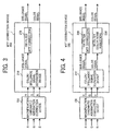
FIG. 1 is a block chart illustrating an exemplary function of an image processing apparatus according to the first embodiment of the present invention; -
FIG. 2 illustrates an exemplary FIR filter; -
FIG. 3 is a block chart illustrating an exemplary function of an image processing apparatus according to the second embodiment of the present invention; -
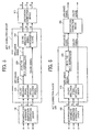
FIG. 4 is a block chart illustrating an exemplary function of an image processing apparatus according to the third embodiment of the present invention; -
FIG. 5 is a block chart illustrating an exemplary function of an image processing apparatus according to the fourth embodiment of the present invention; -
FIG. 6 is a block chart illustrating an exemplary function of an image processing apparatus according to the fifth embodiment of the present invention; -
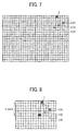
FIG. 7 illustrates an exemplary magnification chromatic aberration and a distortion; -
FIG. 8 illustrates exemplary simultaneous corrections of the magnification chromatic aberration and the distortion; -
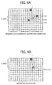
FIGS. 9A and 9B collectively illustrates exemplary independent corrections of the magnification chromatic aberration and the distortion; -
FIG. 10 illustrates an exemplary magnification chromatic aberration correction device; -
FIGS. 11A to 11C collectively illustrates an exemplary magnification chromatic aberration correction coordinate conversion calculation section employed in each of the embodiments; -
FIG. 12 illustrates an exemplary distortion correction device; and -
FIG. 13 is a block chart entirely illustrating an exemplary image forming apparatus, which the present invention is applied to - Referring now to the drawings, wherein like reference numerals and marks designate identical or corresponding parts throughout several figures, in particular in
FIG. 1 , an image processing apparatus is described, in which color components of either addition three primitive colors of Red, Green, and Blue or subtraction three primitive colors of Yellow, Magenta, and Cyan is employed. - As shown, the image processing apparatus includes a magnification chromatic
aberration correction device 100 and aMTF correction device 200. TheMTF correction device 200 includes a color/brightnesssignal separation device 210, a high band emphasis filter (FIR filter) 220, and a color/brightnesssignal combination device 240. - The magnification chromatic
aberration correction device 100 receives RGB image data having a magnification chromatic aberration, which is obtained by photographing with a wide angle optical system having a large magnification chromatic aberration and is read by an imaging element, such as a CCD, a CMOS sensor, etc. The magnification chromaticaberration correction device 100 then converts a coordinate of RGB image data separately using a prescribed polynomial or the like and outputs RGB image data having been subjected to the magnification chromatic aberration correction. The magnification chromaticaberration correction device 100 mentioned later in detail can employ a memory of a small capacity and low latency or a memory such as a SRAM having plural ports and low capacity. - The
MTF correction device 200 receives and separates RGB pixel data subjected to the magnification chromatic aberration correction to a brightness signal and a color signal using the color/brightnesssignal separation device 210. TheMTF correction device 200 applies high band emphasis processing (e.g. MTF correction) to the brightness signal using theFIR filter 220 and combines the brightness signal subjected to the high band emphasis and the color signal in a color/brightness signal-combiningdevice 240. TheMTF correction device 200 then outputs RGB pixel data. - For example, the color/brightness
signal separation device 210 separates the RGB pixel data into a brightness signal Y and color signals Cr and Cb using the following formulas:


- The
FIR filter 220 includes a (5x5) filter and receives and applies the MTF correction only to the brightness signal Y among the brightness signal Y and the color signals Cr and Cb. By only applying the high band emphasis filtering ((MTF correction) to the Y signal, a high quality image is obtained suppressing color noise. An exemplary coefficient of the FIR filter is illustrated inFIG. 2 . - The color/brightness
signal combining device 240 receives and combines the high band emphasized brightness signal Y and the color signals Cr and Cb using the following formulas and outputs RGB pixel data:


- With the construction of
FIG. 1 , the magnification chromatic aberration correction of the RGB can be independently performed appropriately, and the MTF correction of the high band emphasis filtering can only be applied to the brightness signal. As a result, a circuit can be maintained compact while suppressing color noise. - Now, various modifications and improvements of the above-mentioned image processing apparatus are described with reference to
FIGS. 3 to 6 . - As shown in
FIG. 3 , theMTF correction device 200 only includes the colorbrightness signal device 210 and theFIR filter 220 excluding the color brightness signal-combiningdevice 240. When brightness and color signals excluding RGB signals are preferably outputted to a subsequent stage, the configuration ofFIG. 3 is simply employed. The magnification chromaticaberration correction device 100 can be replaced with a magnification chromatic aberration/distortion correction device that independently converts coordinates of RGB image data per component color of RGB and simultaneously corrects the magnification chromatic aberration and distortion. Such replacement can be achieved only by changing parameter of a correction formula (e.g. a coordinate conversion formula). - As shown in
FIG. 4 , aFIR filter 230 is added to the configuration ofFIG. 3 to apply smoothing filtering to a color signal in addition to MTF correction in order to reduce color noise. Also, the magnification chromaticaberration correction device 100 can be replaced with a magnification chromatic aberration/distortion correction device. TheFIR filter 230 for the color signal can be substituted by not only a filter that reduces noise but also that capable of improving color saturation by simply adjusting a gain. To improve sensitivity of an imaging element when used for a dark photographing subject or in dark environment, a gain of a signal read from the imaging element is raised. However, in such a situation, the noise increases. Thus, theFIR filter 230 for noise reduction use for color information is used when the gain is high, and accordingly lightness of the photographing subject decreases (i.e., dark). Otherwise, a coefficient of theFIR filter 230 is changed to change smoothing intensity in accordance with the gain (i.e., the lightness of the photographing subject). The lightness of the photographing subject can be directly read by a lightness sensor provided separately. Further, the coefficient of theFIR filter 230 can be changed by selectively employing one of separately equipped FIR filters having a different coefficient from each other in accordance with the gain (i.e., the lightness). -
FIG. 5 illustrates another modification in which adistortion correction device 300 is newly added to the configuration ofFIG. 1 in the subsequent step of theMTF correction device 200. Thedistortion correction device 300, mentioned later in detail, receives RGB image data subjected to magnification chromatic aberration and MTF corrections and commonly applies the coordinate conversion processing to RGB using a prescribed polynomial expression or the like, and outputs RGB image data subjected to the distortion correction. - The magnification chromatic aberration of RGB is different from each other, but the distortion of those are the same. The distortion is significantly larger than the magnification chromatic aberration. By employing the configuration of
FIG. 5 , a memory, such as a SRAM of a small capacity and low latency, that of a low capacity and multi port, etc., can be used for converting a coordinate for magnification chromatic aberration correction. Whereas a large capacity and high latency memory, such as a DRAM, etc., having a common single port can be used to convert a coordinate for distortion correction. As a result, the entire apparatus can be manufactured at low cost. - Further, when the MTF correction is executed after the distortion correction, an interpolation error created by the coordinate conversion executed for the distortion correction is amplified and thereby affecting image quality. The interpolation error can be reduced by an interpolator that executes interpolation for pixels during the coordinate conversion. However, since the magnification chromatic aberration is relatively smaller than the distortion, affection of an interpolation error to image quality is small in the coordinate conversion for the magnification chromatic aberration correction. Thus, when the magnification chromatic aberration correction, the MTF correction, and the distortion correction are executed in this order as shown in
FIG. 5 , the interpolation error caused by the distortion correction is not amplified by the MTF correction. Beside, since the magnification chromatic aberration correction and the MTF correction can be executed in this order, the finest image quality can be obtained. -
FIG. 6 illustrates still another modification in which adistortion correction device 300 is newly provided in a subsequent stage of theMTF correction device 200 in addition to the configuration ofFIG. 3 . Thedistortion correction device 300 executes distortion correction by coordinate conversion for each of a brightness signal and a color signal. - When brightness and color signals excluding RGB signal are preferably outputted to a subsequent stage, the configuration of
FIG. 6 is simply preferably employed. Further, adistortion correction device 300 as shown inFIG. 6 can be employed in addition to the configuration ofFIG. 4 . - Now, the magnification chromatic
aberration correction device 100 and thedistortion correction device 300 are described in more detail starting with their principle. - As typically shown in
FIG. 7 , when an optical system having a magnification chromatic aberration and distortion executes photographing, image data (pixel data) located at a position (pixel) 1 on the right upper screen deviates from an original position due to the distortion, and further differently deviates from each other therefrom due to the magnification chromatic aberration among the respective color components of RGB, thereby positioning at 2(R), 3(G), and 4(B), respectively. The magnification chromatic aberration and the distortion can be corrected by copying image data of RGB color components positioning at 2(R), 3(G), and 4(B), respectively, onto a position 1 (pixel) serving as an original position. That is, the correction is achieved by converting the coordinate. Thus, thepositions position 1 serves as a coordinate conversion destination. - Since levels of the distortion and the magnification chromatic aberration can be known from design data of an optical system, positions where RGB color components deviate from the origins can be calculated.
-
FIG. 8 typically illustrates a method of simultaneously correcting the distortion and the magnification chromatic aberration. As shown, the magnification chromatic aberration and the distortion can be simultaneously corrected by copying image data of RGB components positioning at 2(R), 3(G), and 4(B) (pixel), respectively, onto a position 1 (pixel) serving as an original position of those. That is, the correction is simultaneously executed by converting the coordinate. However, such a method necessitates a large capacity memory of either low latency or a multi port per RGB color component. For example, a six line high-speed memory is needed to convert a coordinate per component color (RGB) in this example. -
FIG. 9 typically illustrates a method of independently correcting a distortion and a magnification chromatic aberration. The magnification chromatic aberration of the respective RGB color components is different from each other but is small. Whereas the distortion is large but is the same. In view of this, a coordinate of image data of each of the respective RGB color components is initially converted (coordinates of color components of RB are converted and copied onto a position of G component in the later described embodiment) and the magnification chromatic aberration is corrected. Then, the coordinates of RGB image data subjected to the magnification chromatic aberration correction are converted at once so that the distortion is corrected. As a result, coordinate correction use memories can be divided into two. That is, a small capacity and high-speed (low latency or multi port) memory is provided for RGB capable of correcting the magnification chromatic aberration, while a large capacity and low speed (high latency or single port) memory is provided and commonly used by RGB for correcting the distortion. Accordingly, the cost can be reduced as a whole. -
FIG. 9A typically illustrates correction of the magnification chromatic aberration. Coordinates of image data of the respective RB color components existing at the positions (pixel) 2(R) and 4(B) are converted and are copied onto a position (pixels) 3(G) of the G component, thereby the magnification chromatic aberration is corrected.FIG. 9B typically illustrates correction of the distortion. Coordinates of image data of the respective RGB color components existing at the position 3 (pixel) having been subjected to magnification chromatic aberration correction are converted in a block, and are copied onto the position (pixel) 1 serving as an original position, thereby the distortion is corrected. - In
FIG. 9 , the high-speed memory for the magnification chromatic aberration correction use is preferably a three-line memory handling respective RGB. A five-line memory is needed for distortion correction and a low speed memory is employed while a one port is commonly used by the RGB. As a result, the cost can be reduced as a whole in comparison withFIG. 8 . - The distortion represents deformation of a lens in relation to a projection system, in which a looked down image is obtained from above a camera or that is partially expanded and displayed.
- An exemplary configuration of a magnification chromatic
aberration correction device 100 is illustrated inFIG. 10 . 110 denotes a magnification chromatic aberration correction use coordinate conversion memory (a line buffer), and respective 110(R), 110(G), and 110(B) correspond to respective RGB color components. 120 denotes a magnification chromatic aberration correction coordinate conversion calculation section that calculates a conversion coordinate for magnification chromatic aberration correction per each of the RGB in accordance with a prescribed coordinate conversion formula. 130 denotes a coordinate conversion coefficient table that stores coefficients used by the prescribed coordinate conversion formula. - To execute the magnification chromatic aberration correction, a small capacity memory having a RGB three ports or that having a low latency is needed as a line buffer. Supposing that the maximum deviation amount of magnification chromatic aberration amounts to twenty lines in the direction Y, each of the coordinate conversion memories 142(R) to 142(B) can include a SRAM having twenty lines.
A size in the direction X is determined by resolution, and it is 640 dots when the resolution is VGA (640 x 480). Color depth is RGB eight bit, so that writing and reading operations to and from respective coordinate conversion memories 142(R) to 142(B) are executed in a unit of eight bits. - Since each of the magnification chromatic aberration correction use coordinate conversion memories (line buffers) 110(R) to 110(B) has a small capacity, a memory region having twenty lines is preferably maintained using the three port SRAM provided in an image-processing chip. When a low latency memory such as a SRAM is used, a memory having one port can be used as a three-port memory by timesharing.
- Respective RGB image data subjected to magnification chromatic aberration correction are sequentially written into the coordinate conversion memories 110(R) to 110(B) from the leading line thereof in accordance with a coordinate value (x, y). When each of the image data of the twenty lines are written, the image data are sequentially disposed from the leading line and image data of subsequent lines are newly written. In this way, the coordinate conversion memories 110(R) to 110(B) are sequentially stored with the RGB image data having maximum twenty lines needed for magnification chromatic aberration correction coordinate conversion, respectively.
- The coordinate value (x, y) represents a position for reading a photograph image of one frame. Where as since the coordinate conversion memories 110(R) to 110(B) are the twenty line buffers and a writing line varies in a cyclic, the coordinate value (x, y) cannot be used as is as a writing address of each of the coordinate conversion memories 110(R) to 110(B). For this reason, the coordinate value (x, y) needs to be converted into an actual address of each of the coordinate conversion memories 110(R) to 110(B). However, a configuration therefor is not shown in
FIG. 10 . It is the same in a relation between a coordinate value (x, y) subjected to conversion in a reading operation as mentioned later and a reading address of each of the coordinate conversion memories 110(R) to 110(B). - The magnification chromatic aberration correction coordinate
conversion calculation section 120 receives the coordinate value (x, y) serving as a coordinate conversion destination coordinate and calculates a conversion coordinate for magnification chromatic aberration correction per each of the RGB. The aberration correction coordinateconversion calculation section 120 then outputs a coordinate (X, Y) serving as a coordinate conversion origin coordinate per each of the RGB. - As shown in
FIG. 9A , coordinates of color components RB are converted and copied onto a position of a G component. Thus, the magnification chromatic aberration correction coordinateconversion calculation section 120 outputs the coordinate value (x, y) as is as the coordinate value (X, Y) for the G color component. Whereas the magnification chromatic aberration correction coordinateconversion calculation section 120 converts the coordinate value (x, y) into the coordinate value (X, Y) using a prescribed coordinate conversion formula and outputs the same for the RB color components. The magnification chromatic aberration correction coordinateconversion calculation section 120 repeats this per coordinate value (x, y). - Such a coordinate conversion formula can be represented as follows premising that a center of the screen serves as a original point, wherein abs () represents an absolute value, and a(1) to a(4) and b(1) to b(4) represent coordinate conversion coefficients;

- The coordinate conversion coefficients are previously stored in a coordinate conversion coefficient table 130.
- The coordinate conversion memories 110(R) to 110(B) each sequentially reads the respective RGB image data based on a coordinate value (X, Y) outputted from the magnification chromatic aberration correction coordinate conversion calculation section 120 (precisely, an address converted coordinate value (X, Y)) in parallel to a writing operation (precisely, with a prescribed delay). In such a situation, in the coordinate conversion memory 110G, the G component image data are read from the same position as written. In the coordinate conversion memories 110R and 110B, R and B color component image data are read from positions deviated from the writing position by a difference of a magnification chromatic aberration, respectively.
- Hence, the RGB image data subjected to the magnification chromatic aberration correction are outputted from the coordinate conversion memories 110R to 110B, respectively. Specifically, the RGB image data of the coordinate conversion origin coordinate value (X, Y) are outputted as RGB image data of the coordinate conversion destination coordinate value (x, y).
- Now, several examples of the magnification chromatic aberration correction coordinate
conversion calculation section 120 are described with reference toFIGS. 11A to 11C . In an example ofFIG. 11A , a G color component is not subjected to coordinate conversion and a coordinate value (x, y) is outputted as is inputted as a G color use coordinate (X, Y). Whereas only coordinate values (x, y) of RB color components are subjected to coordinate conversion in coordinateconversion calculation sections - Examples of
FIGS. 11B and 11C pay attention to the fact that components of R and B colors symmetrically deviate from a component of G color serving as a deviation center (seeFIG. 7 ). As shown inFIG. 11B , a correction value as to a coordinate value (x, y) is calculated by the coordinateconversion calculation section 123, and a B use coordinate value (X, Y) is obtained by subtracting the correction value from the coordinate value (x, y) in asubtraction section 124, while a R use coordinate value (X, Y) is obtained by adding the correction value to the coordinate value (x, y) in anaddition section 125. As in the example ofFIG. 11A , a coordinate value (x, y) is outputted as is inputted to the G use coordinate value (X, Y). - Considering deviation at a symmetrical position, a
gain circuit 126 is provided to adjust a R use correction amount as shown inFIG. 11C . Thegain circuit 126 can be arranged on the B color component side.
According to the examples ofFIGS. 11B and 11C , only one coordinate conversion calculation section is needed thereby further downsizing the circuit. - In place of the coordinate
conversion calculation sections FIG. 11A , a look up table (LUT) storing a correspondence of an input coordinate value (x, y) to an output coordinate value (X, Y) is provided fro each of R and B, and a coordinate value (X, Y) of a coordinate conversion origin corresponding to a coordinate value (x, y) of coordinate conversion destination can directly be obtained using the LUT. Similarly, in place of the coordinateconversion calculation section 123 ofFIGS. 11B and 11C , a look up table (LUT) storing a correspondence of an input coordinate value (x, y) to a correction amount is provided, and a correction amount corresponding to the coordinate value (x, y) can directly be obtained using the LUT. Thus, calculation for coordinate conversion can be omitted, so that magnification chromatic aberration correction can essentially be achieved only by a memory chip. - Now, an exemplary distortion correction section 300 (
FIG. 5 ) is described with reference toFIG. 12 . 310 denotes a RGB combining section for combining three RGB image data into one. 320 denotes a distortion correction use coordinate conversion memory commonly used for RGB image data. 163 denotes a RGB separation section for separating combined RGB image data into respective original color components. 340 denotes a distortion correction coordinate conversion calculation section for calculating a conversion coordinate for distortion correction in accordance with a prescribed coordinate conversion formula. 350 denotes a coordinate conversion coefficient table storing coefficients used in the coordinate conversion formula. - Since a distortion largely deviates a pixel, a buffer memory at most storing image data of one screen is needed for the distortion correction. Since a deviation amount is the same among the respective RGB color components, only one buffer memory having a bit width corresponding to the total of RGB image data is needed. For example, it is premised in this embodiment that resolution amounts to VGA(640 x 480), each of bit numbers (color depth) of RGB image data is eight, and the coordinate
conversion memory 320 includes a DRAM having 640 x 480 dot capable of writing and reading in a unit of twenty-four bits. - In this way, since the distortion correction use coordinate
conversion memory 320 necessitates an extraordinary large capacity, such a SRAM is hardly provided in an image-processing chip in view of cost.
In addition, since only one port memory is needed for handling the RGB, a DRAM provided outside the image-processing chip is preferably used. - The
RGB combining section 310 sequentially receives respective RGB image data (eight bit) already subjected to magnification chromatic aberration correction and combines them into image data (twenty-four bit) and outputs the same. The thus combined RGB image data are sequentially written into the coordinateconversion memory 320 starting from the leading line in accordance with the coordinate values (x, y) of the respective coordinate conversion destinations. - The distortion correction coordinate
conversion calculation section 340 receives the coordinate value (x, y) of the coordinate conversion destination, and calculates a conversion coordinate for distortion correction commonly used for the RGB, and outputs a coordinate value (X, Y) of the coordinate conversion origin.
The coordinate conversion formula can be the formula 13 used in the magnification chromatic aberration correction as mentioned earlier. However, coordinate conversion coefficients used there are of course different from those in the formula. Such coordinate conversion coefficients can previously be stored in a coordinate conversion coefficient table 350. - In parallel to the writing operation of the earlier mentioned RGB combination image data (twenty four bit) (precisely with a prescribed delay), the RGB combination image data are sequentially read in accordance with the coordinate value (X, Y) outputted from the distortion correction coordinate
conversion section 340. TheRGB separation section 330 separates the RGB combination image data (24 bit) read from the coordinateconversion memory 320 into image data (8 bit) of the RGB original color components. - Hence, the
RGB separation section 330 outputs respective RGB image data subjected to the distortion correction. Specifically, the respective RGB image data are copied onto the original positions of the coordinate value (x, y). - Also in the distortion correction processing, a look up table (LUT) storing correspondence of an input coordinate value (x, y) to an output coordinate value (X, Y) is provided, and a coordinate value (X, Y) of a coordinate conversion origin corresponding to a coordinate value (x, y) of a coordinate conversion destination can directly be obtained using the LUT. Thus, calculation for the coordinate conversion can be omitted, and the distortion correction can essentially be achieved only by a memory chip.
- As shown the configuration of
FIG. 12 corresponds to that ofFIG. 5 . In case of corresponding to the configuration ofFIG. 6 , neither theRGB combination section 310 nor theRGB separation section 330 is needed, and instead, the brightness and color signals are provided to the coordinateconversion memory 320. - Now, exemplary functional blocks of an imaging apparatus, to which one embodiment of the present invention is applied, are described with reference to
FIG. 13 . The imaging apparatus additionally includes an operation section, an image storage, and an image display (a monitor), not shown. The imaging apparatus is used as a camera mounted on a car but is not limited thereto. - In
FIG. 13 , acontrol section 1000 provides each of sections with necessary control signals, such as a clock, a horizontally/vertically synchronizing signal, etc., and controls each of the sections in a pipe line manner. - An
imaging element 1100 includes a CCD or a CMOS sensor or the like for converting an optical image into an electric signal (image data), which is obtained using an optical system, not shown, having a wide angle and a large magnification chromatic aberration and distortion.
Theimaging element 1100 includes a color filter of Beyer arrangement, and thus RGB image data in the Beyer arrangement are sequentially outputted in accordance with coordinate values (x, y) provided by thecontrol section 1000. Further, thecontrol section 1000 deviates the coordinate values (x, y) provided to theimaging element 1100 by a prescribed time one after another and provides those to a subsequent step. Such coordinate values (x, y) can be generated in theimaging element 1100 based on an input of a clock and a horizontally or vertically synchronizing signal, and is outputted one by one to the subsequent steps. - An A/
D converter 1200 converts the RGB image data of Beyer arrangement outputted from theimaging element 1100 in a state of an analog signal into a digital signal and launches the same to aBeyer complement section 1300. The digital signal of each of the RGB includes 8 bit.
In general, an AGC circuit, not shown, is arranged in a previous step of the A/D converter 1200. A lightness of the photographing subject can be detected by checking an amount of gain of the AGC circuit. - A
Beyer supplementing section 1300 receives the RGB image data of the Beyer arrangement of the digital signals, and generates image data of the entire coordinate positions by means of linear supplement per each of the RGB independently. TheBeyer complement section 1300 then launches the image data to a magnification chromaticaberration correction section 1400. - Although the imaging element having the color filer of the Beyer arrangement is employed as mentioned above, the present invention is also effective to that having the other color filter arrangement, such as a CMYG arrangement, a RGB + Ir (infrared) arrangement, etc. The imaging element having such a four color filter arrangement further necessitates a low latency memory or a four port RAM for magnification chromatic aberration correction as different from a three-color type, such as a RGB, etc.
- The magnification chromatic
aberration correction section 1400 receives Beyer supplemented R, G and B image data and applies coordinate conversion (e.g. magnification chromatic aberration coordinate conversion) independently to each of the RGB color components using a prescribed polynomial formula, and outputs RGB image data subjected to magnification chromatic aberration correction. As mentioned earlier, to execute coordinate conversion for the magnification chromatic aberration correction, a memory of small capacity and low latency or a SRAM having a low capacity and plural ports can be utilized. - A
MTF correction section 1500 receives RGB image data subjected to the magnification chromatic aberration correction and applies MTF correction processing to a brightness signal using a FIR filter, and outputs RGB image data subjected to the MTF correction. As mentioned earlier, by only applying high band emphasis filtering (e.g. the MTF correction) to the brightness signal, a high quality image suppressing color noise can be obtained. TheMTF correction section 1500 can apply smoothing filtering to the color signal in parallel to the high band emphasis filtering to the brightness signal. - A
distortion correction section 1600 receives the RGB image data subjected to the magnification chromatic aberration and MTF corrections, and commonly applies coordinate conversion (distortion coordinate conversion) to respective RGB color components using a prescribed polynomial formula or the like, and outputs RGB image data subjected to the distortion correction. As mentioned earlier, to execute the coordinate conversion for the distortion correction, a large capacity (e.g. at most one screen amount) but high latency memory, such as a DRAM, etc., can be used. Because, only one port is needed as different from a memory for magnification chromatic aberration correction use. - A
gamma correction section 1700 receives the RGB image data outputted from the distortion correction section, and applies prescribed gamma correction processing thereto using a LUT or the like prepared for each of RGB, and outputs RGB image data subjected to the gamma correction. The image data outputted from thegamma correction section 1700 is displayed on a display section, not shown. - Owing to the configuration of
FIG. 13 , a high quality compact circuit and low cost imaging system can be provided to the optical system having the magnification chromatic aberration and the distortion. The magnification chromaticaberration correction section 1400 can be a magnification chromatic aberration/distortion correction section capable of simultaneously correcting the magnification chromatic aberration and distortion. In such a situation, thedistortion correction section 1600 can be omitted. Further, thegamma correction section 1700 can be arranged right after theBeyer correction section 1300. - Further, the above-mentioned processing function of the image processing apparatus shown in
FIGS. 1 and3-6 or the like can be established by computer program. Also, the image processing method can be implemented by the computer that reads the program in the present invention. Otherwise, the above-mentioned operation procedure can be established by computer program. Also, the image processing method of the present invention can be implemented by the computer that reads the program. Such program can be recorded in a computer readable medium, such as a FD, a MO, a ROM, a memory card, a CD, a DVD, a removable Disc, etc., to be preserved or offered. Further, the program can be distributed through a network such as an intra net, etc.
Obviously, numerous additional modifications and variations of the present invention are possible in light of the above teachings. It is therefore to be understood that within the scope of the appended claims, the present invention may be practiced otherwise than as specifically described herein.
Claims (14)
- An image processing method of processing an image obtained using an optical system having a wide field angle and a large magnification chromatic aberration, said method comprising the steps of:applying magnification chromatic aberration correction processing to the image;applying separation processing to the image after the step of applying the magnification chromatic aberration correction for separating the image into a brightness signal and a color signal; andapplying a high band emphasis processing only to the brightness signal after the step of applying the separation processing.
- The image processing method as claimed in claim 1, further comprising the step of combining the brightness signal subjected to the high band emphasis processing and the color signal.
- The image processing method as claimed in claim 2, further comprising the step of smoothing the color signal in parallel to the high band emphasis processing of the brightness signal.
- The image processing method as claimed in claim 3, further comprising the step of changing an intensity of the smoothing in accordance with a luminance of a photographic subject.
- The image processing method as claimed in claim 3, wherein said step of smoothing the color signal is executed only when the luminance decreases to a prescribed dark level.
- The image processing method as claimed in claim 1, wherein said magnification chromatic aberration correction is executed by partially converting coordinates of multi color components in the step of executing the magnification chromatic aberration correction processing.
- The image processing method as claimed in claim 6, and wherein a coordinate conversion amount of a first color component is calculated with reference to a coordinate of a reference color component, and wherein a coordinate conversion amount of a second color component is calculated in accordance with the coordinate conversion amount of the first color component.
- The image processing method as claimed in claim 7, further comprising a step of applying distortion correction processing to the image separately from the step of applying magnification chromatic aberration correction processing.
- The image processing method as claimed in claim 8, wherein said step of applying distortion correction processing is executed after the step of applying the high band emphasis processing.
- The image processing method as claimed in claim 7, wherein further comprising a step of applying distortion correction processing to the image is executed simultaneously with the step of applying magnification chromatic aberration correction processing.
- An image processing apparatus for processing an image obtained by an optical system having a wide field angle and a large magnification chromatic aberration, comprising:a magnification chromatic aberration correction device configured to correct magnification chromatic aberration per color component by converting a coordinate of the image;a separation device configured to separate the image subjected to the magnification chromatic aberration correction into brightness and color signals; anda MTF correction device including a filter configured to emphasize a high band of the brightness signal.
- The image processing apparatus as claimed in claim 11, further comprising a combining device configured to combine the brightness signal subjected to the high band emphasis and the color signal.
- The image processing apparatus as claimed in claim 12, wherein said MTF correction device further comprising a filter configured to smooth the color signal.
- The image processing apparatus as claimed in claim 13, wherein an intensity of smoothing by the filter is changed in accordance with the lightness of a photographic subject.
Applications Claiming Priority (1)
| Application Number | Priority Date | Filing Date | Title |
|---|---|---|---|
| JP2008053718A JP5078147B2 (en) | 2008-03-04 | 2008-03-04 | Image processing apparatus and image pickup apparatus |
Publications (2)
| Publication Number | Publication Date |
|---|---|
| EP2099229A1 true EP2099229A1 (en) | 2009-09-09 |
| EP2099229B1 EP2099229B1 (en) | 2011-06-22 |
Family
ID=40785413
Family Applications (1)
| Application Number | Title | Priority Date | Filing Date |
|---|---|---|---|
| EP09154262A Ceased EP2099229B1 (en) | 2008-03-04 | 2009-03-04 | Image processing method and apparatus |
Country Status (4)
| Country | Link |
|---|---|
| US (1) | US8417031B2 (en) |
| EP (1) | EP2099229B1 (en) |
| JP (1) | JP5078147B2 (en) |
| CN (1) | CN101527858B (en) |
Cited By (2)
| Publication number | Priority date | Publication date | Assignee | Title |
|---|---|---|---|---|
| EP2566162A3 (en) * | 2011-08-31 | 2013-04-10 | Canon Kabushiki Kaisha | Image processing apparatus and method |
| US8971622B2 (en) | 2011-08-31 | 2015-03-03 | Canon Kabushiki Kaisha | Image processing apparatus, image capture apparatus, and image processing method |
Families Citing this family (17)
| Publication number | Priority date | Publication date | Assignee | Title |
|---|---|---|---|---|
| JP5273371B2 (en) | 2008-12-24 | 2013-08-28 | 株式会社リコー | Image processing apparatus and method, and in-vehicle camera apparatus |
| JP5267794B2 (en) | 2008-12-26 | 2013-08-21 | 株式会社リコー | Image processing apparatus and in-vehicle camera apparatus |
| JP5607911B2 (en) * | 2009-10-21 | 2014-10-15 | オリンパスイメージング株式会社 | Image processing apparatus, imaging apparatus, image processing method, and image processing program |
| US8624999B2 (en) | 2009-12-01 | 2014-01-07 | Ricoh Company, Ltd. | Imaging apparatus |
| JP2011215707A (en) | 2010-03-31 | 2011-10-27 | Canon Inc | Image processing apparatus, imaging apparatus, image processing method, and program |
| JP5585885B2 (en) | 2011-03-18 | 2014-09-10 | 株式会社リコー | Image processing apparatus and image processing method |
| JP2013017142A (en) * | 2011-07-06 | 2013-01-24 | Sony Corp | Image processing apparatus, imaging apparatus, image processing method, and program |
| JP6417666B2 (en) | 2013-05-15 | 2018-11-07 | 株式会社リコー | Image processing system |
| JP2015231052A (en) * | 2014-06-03 | 2015-12-21 | ソニー株式会社 | Imaging apparatus and method, and program |
| JPWO2016207990A1 (en) * | 2015-06-24 | 2018-04-05 | オリンパス株式会社 | Image processing apparatus, imaging apparatus, image processing method, image processing program, and storage medium |
| JP6876941B2 (en) | 2016-10-14 | 2021-05-26 | パナソニックIpマネジメント株式会社 | Virtual make-up device, virtual make-up method and virtual make-up program |
| JP2018085008A (en) | 2016-11-25 | 2018-05-31 | 株式会社ジャパンディスプレイ | Image processing apparatus and image processing method of image processing apparatus |
| CN107566747B (en) * | 2017-09-22 | 2020-02-14 | 浙江大华技术股份有限公司 | Image brightness enhancement method and device |
| US10559276B2 (en) | 2018-02-03 | 2020-02-11 | Facebook Technologies, Llc | Apparatus, system, and method for mitigating motion-to-photon latency in head-mounted displays |
| US10706813B1 (en) | 2018-02-03 | 2020-07-07 | Facebook Technologies, Llc | Apparatus, system, and method for mitigating motion-to-photon latency in head-mounted displays |
| KR102057602B1 (en) * | 2018-04-26 | 2019-12-20 | 주식회사 텐앤투 | Wide angle image providing method and system |
| US10678325B2 (en) | 2018-05-22 | 2020-06-09 | Facebook Technologies, Llc | Apparatus, system, and method for accelerating positional tracking of head-mounted displays |
Citations (7)
| Publication number | Priority date | Publication date | Assignee | Title |
|---|---|---|---|---|
| WO1985005526A1 (en) * | 1984-05-19 | 1985-12-05 | Robert Bosch Gmbh | Method for enhancing the resolution of colour television cameras |
| US6587224B1 (en) * | 1998-09-14 | 2003-07-01 | Minolta Co., Ltd. | Image reading apparatus that can correct chromatic aberration caused by optical system and chromatic aberration correction method |
| US20030184659A1 (en) * | 2002-04-02 | 2003-10-02 | Michael Skow | Digital color image pre-processing |
| US20040227978A1 (en) * | 2001-09-27 | 2004-11-18 | Fuji Photo Film Co., Ltd. | Image processor |
| US20040247201A1 (en) * | 2003-03-05 | 2004-12-09 | Shinichi Arazaki | Chromatic aberration correction apparatus, chromatic aberration correction method, and chromatic aberration correction program |
| EP1523172A2 (en) * | 2003-10-07 | 2005-04-13 | Sony Corporation | Image pick-up apparatus, image processing apparatus and method of correcting chromatic aberration of lens |
| JP2006345054A (en) | 2005-06-07 | 2006-12-21 | Olympus Corp | Imaging device |
Family Cites Families (27)
| Publication number | Priority date | Publication date | Assignee | Title |
|---|---|---|---|---|
| US5398124A (en) * | 1991-06-29 | 1995-03-14 | Minolta Camera Kabushiki Kaisha | Image processor |
| JPH06335006A (en) * | 1993-05-19 | 1994-12-02 | Matsushita Electric Ind Co Ltd | Solid-state image pickup device |
| JP3399486B2 (en) * | 1993-06-30 | 2003-04-21 | 富士ゼロックス株式会社 | Color image processing apparatus and method |
| JP3267200B2 (en) * | 1997-07-11 | 2002-03-18 | 松下電器産業株式会社 | Image processing device |
| US6603885B1 (en) * | 1998-04-30 | 2003-08-05 | Fuji Photo Film Co., Ltd. | Image processing method and apparatus |
| US6853400B1 (en) * | 1998-06-16 | 2005-02-08 | Fuji Photo Film Co., Ltd. | System and method for correcting aberration of lenses through which images are projected |
| US6870564B1 (en) * | 1998-10-02 | 2005-03-22 | Eastman Kodak Company | Image processing for improvement of color registration in digital images |
| JP3861498B2 (en) * | 1999-03-19 | 2006-12-20 | コニカミノルタビジネステクノロジーズ株式会社 | Black edge discrimination device and image processing device |
| JP2001275029A (en) * | 2000-03-28 | 2001-10-05 | Minolta Co Ltd | Digital camera, image signal processing method thereof, and recording medium |
| US6584287B2 (en) * | 2000-10-18 | 2003-06-24 | Fuji Photo Film Co., Ltd. | Camera and image forming system using the camera |
| JP4150844B2 (en) * | 2001-07-05 | 2008-09-17 | コニカミノルタビジネステクノロジーズ株式会社 | Image processing apparatus and image processing program |
| JP2003235050A (en) * | 2002-02-12 | 2003-08-22 | Nikon Corp | Image processing apparatus, image processing program, and image processing method |
| US20040085459A1 (en) * | 2002-02-12 | 2004-05-06 | Nikon Corporation | Image processing device, image processing program, and image processing method |
| JP2004241991A (en) * | 2003-02-05 | 2004-08-26 | Minolta Co Ltd | Imaging apparatus, image processor, and image processing program |
| JP4378994B2 (en) * | 2003-04-30 | 2009-12-09 | ソニー株式会社 | Image processing apparatus, image processing method, and imaging apparatus |
| JP4333544B2 (en) * | 2004-02-13 | 2009-09-16 | セイコーエプソン株式会社 | Image processing method, image processing apparatus, semiconductor device, electronic device, image processing program, and computer-readable recording medium |
| US7580070B2 (en) * | 2005-03-31 | 2009-08-25 | Freescale Semiconductor, Inc. | System and method for roll-off correction in image processing |
| US7920200B2 (en) * | 2005-06-07 | 2011-04-05 | Olympus Corporation | Image pickup device with two cylindrical lenses |
| WO2007037229A1 (en) * | 2005-09-29 | 2007-04-05 | Nikon Corporation | Image processing apparatus and image processing method |
| JP4469324B2 (en) * | 2005-11-01 | 2010-05-26 | イーストマン コダック カンパニー | Chromatic aberration suppression circuit and chromatic aberration suppression program |
| KR101201672B1 (en) * | 2005-12-20 | 2012-11-15 | 삼성전자주식회사 | Apparatus for digital image signal processing and method thereof |
| JP4709084B2 (en) * | 2006-07-07 | 2011-06-22 | キヤノン株式会社 | Image processing apparatus and image processing method |
| JP5046789B2 (en) * | 2007-08-20 | 2012-10-10 | キヤノン株式会社 | Image processing apparatus and image processing method |
| JP5008139B2 (en) * | 2007-11-26 | 2012-08-22 | 株式会社リコー | Imaging device |
| JP5152491B2 (en) * | 2008-02-14 | 2013-02-27 | 株式会社リコー | Imaging device |
| JP5078148B2 (en) * | 2008-03-10 | 2012-11-21 | 株式会社リコー | Image processing apparatus and image pickup apparatus |
| JP5171361B2 (en) * | 2008-04-07 | 2013-03-27 | 株式会社日立製作所 | Imaging device |
-
2008
- 2008-03-04 JP JP2008053718A patent/JP5078147B2/en not_active Expired - Fee Related
-
2009
- 2009-03-04 CN CN2009100044761A patent/CN101527858B/en not_active Expired - Fee Related
- 2009-03-04 US US12/379,889 patent/US8417031B2/en not_active Expired - Fee Related
- 2009-03-04 EP EP09154262A patent/EP2099229B1/en not_active Ceased
Patent Citations (7)
| Publication number | Priority date | Publication date | Assignee | Title |
|---|---|---|---|---|
| WO1985005526A1 (en) * | 1984-05-19 | 1985-12-05 | Robert Bosch Gmbh | Method for enhancing the resolution of colour television cameras |
| US6587224B1 (en) * | 1998-09-14 | 2003-07-01 | Minolta Co., Ltd. | Image reading apparatus that can correct chromatic aberration caused by optical system and chromatic aberration correction method |
| US20040227978A1 (en) * | 2001-09-27 | 2004-11-18 | Fuji Photo Film Co., Ltd. | Image processor |
| US20030184659A1 (en) * | 2002-04-02 | 2003-10-02 | Michael Skow | Digital color image pre-processing |
| US20040247201A1 (en) * | 2003-03-05 | 2004-12-09 | Shinichi Arazaki | Chromatic aberration correction apparatus, chromatic aberration correction method, and chromatic aberration correction program |
| EP1523172A2 (en) * | 2003-10-07 | 2005-04-13 | Sony Corporation | Image pick-up apparatus, image processing apparatus and method of correcting chromatic aberration of lens |
| JP2006345054A (en) | 2005-06-07 | 2006-12-21 | Olympus Corp | Imaging device |
Cited By (3)
| Publication number | Priority date | Publication date | Assignee | Title |
|---|---|---|---|---|
| EP2566162A3 (en) * | 2011-08-31 | 2013-04-10 | Canon Kabushiki Kaisha | Image processing apparatus and method |
| US8971622B2 (en) | 2011-08-31 | 2015-03-03 | Canon Kabushiki Kaisha | Image processing apparatus, image capture apparatus, and image processing method |
| US9167216B2 (en) | 2011-08-31 | 2015-10-20 | Canon Kabushiki Kaisha | Image processing apparatus, image capture apparatus and image processing method |
Also Published As
| Publication number | Publication date |
|---|---|
| EP2099229B1 (en) | 2011-06-22 |
| CN101527858A (en) | 2009-09-09 |
| US20090226086A1 (en) | 2009-09-10 |
| CN101527858B (en) | 2012-01-25 |
| JP2009212818A (en) | 2009-09-17 |
| JP5078147B2 (en) | 2012-11-21 |
| US8417031B2 (en) | 2013-04-09 |
Similar Documents
| Publication | Publication Date | Title |
|---|---|---|
| EP2099229B1 (en) | Image processing method and apparatus | |
| EP2101295B1 (en) | Image processing method, image processing device, and image capturing device | |
| US8035068B2 (en) | Imaging device and imaging apparatus | |
| JP4911628B2 (en) | Image processing method, image processing apparatus, and image pickup apparatus | |
| JP5267794B2 (en) | Image processing apparatus and in-vehicle camera apparatus | |
| TWI486062B (en) | Image pickup apparatus | |
| EP2104363B1 (en) | Image pickup device | |
| EP2104362B1 (en) | Imaging apparatus | |
| JP5062846B2 (en) | Imaging device | |
| EP2083572B1 (en) | Image processing method, image processing apparatus, and imaging apparatus | |
| JP5049155B2 (en) | Progressive interlace conversion method, image processing apparatus, and image capturing apparatus | |
| KR101265000B1 (en) | Method and apparatus for image processing and on-vehicle camera apparatus | |
| JP2009194573A (en) | Image processing method and apparatus, and image pickup apparatus | |
| JP4687454B2 (en) | Image processing apparatus and imaging apparatus | |
| WO1999025123A1 (en) | Color signal processing circuit |
Legal Events
| Date | Code | Title | Description |
|---|---|---|---|
| PUAI | Public reference made under article 153(3) epc to a published international application that has entered the european phase |
Free format text: ORIGINAL CODE: 0009012 |
|
| AK | Designated contracting states |
Kind code of ref document: A1 Designated state(s): AT BE BG CH CY CZ DE DK EE ES FI FR GB GR HR HU IE IS IT LI LT LU LV MC MK MT NL NO PL PT RO SE SI SK TR |
|
| AX | Request for extension of the european patent |
Extension state: AL BA RS |
|
| 17P | Request for examination filed |
Effective date: 20100125 |
|
| AKX | Designation fees paid |
Designated state(s): DE FR GB |
|
| GRAP | Despatch of communication of intention to grant a patent |
Free format text: ORIGINAL CODE: EPIDOSNIGR1 |
|
| GRAS | Grant fee paid |
Free format text: ORIGINAL CODE: EPIDOSNIGR3 |
|
| GRAA | (expected) grant |
Free format text: ORIGINAL CODE: 0009210 |
|
| AK | Designated contracting states |
Kind code of ref document: B1 Designated state(s): DE FR GB |
|
| REG | Reference to a national code |
Ref country code: GB Ref legal event code: FG4D |
|
| REG | Reference to a national code |
Ref country code: DE Ref legal event code: R096 Ref document number: 602009001579 Country of ref document: DE Effective date: 20110804 |
|
| PLBE | No opposition filed within time limit |
Free format text: ORIGINAL CODE: 0009261 |
|
| STAA | Information on the status of an ep patent application or granted ep patent |
Free format text: STATUS: NO OPPOSITION FILED WITHIN TIME LIMIT |
|
| 26N | No opposition filed |
Effective date: 20120323 |
|
| REG | Reference to a national code |
Ref country code: DE Ref legal event code: R097 Ref document number: 602009001579 Country of ref document: DE Effective date: 20120323 |
|
| REG | Reference to a national code |
Ref country code: FR Ref legal event code: PLFP Year of fee payment: 8 |
|
| REG | Reference to a national code |
Ref country code: FR Ref legal event code: PLFP Year of fee payment: 9 |
|
| REG | Reference to a national code |
Ref country code: FR Ref legal event code: PLFP Year of fee payment: 10 |
|
| PGFP | Annual fee paid to national office [announced via postgrant information from national office to epo] |
Ref country code: GB Payment date: 20180321 Year of fee payment: 10 |
|
| PGFP | Annual fee paid to national office [announced via postgrant information from national office to epo] |
Ref country code: FR Payment date: 20180330 Year of fee payment: 10 |
|
| GBPC | Gb: european patent ceased through non-payment of renewal fee |
Effective date: 20190304 |
|
| PG25 | Lapsed in a contracting state [announced via postgrant information from national office to epo] |
Ref country code: GB Free format text: LAPSE BECAUSE OF NON-PAYMENT OF DUE FEES Effective date: 20190304 |
|
| PG25 | Lapsed in a contracting state [announced via postgrant information from national office to epo] |
Ref country code: FR Free format text: LAPSE BECAUSE OF NON-PAYMENT OF DUE FEES Effective date: 20190331 |
|
| REG | Reference to a national code |
Ref country code: DE Ref legal event code: R079 Ref document number: 602009001579 Country of ref document: DE Free format text: PREVIOUS MAIN CLASS: H04N0009040000 Ipc: H04N0023100000 |
|
| P01 | Opt-out of the competence of the unified patent court (upc) registered |
Effective date: 20230522 |
|
| PGFP | Annual fee paid to national office [announced via postgrant information from national office to epo] |
Ref country code: DE Payment date: 20240320 Year of fee payment: 16 |
|
| REG | Reference to a national code |
Ref country code: DE Ref legal event code: R119 Ref document number: 602009001579 Country of ref document: DE |
|
| PG25 | Lapsed in a contracting state [announced via postgrant information from national office to epo] |
Ref country code: DE Free format text: LAPSE BECAUSE OF NON-PAYMENT OF DUE FEES Effective date: 20251001 |