EP2098945A1 - Motion-sensing program and electronic compass using the same - Google Patents
Motion-sensing program and electronic compass using the same Download PDFInfo
- Publication number
- EP2098945A1 EP2098945A1 EP07850129A EP07850129A EP2098945A1 EP 2098945 A1 EP2098945 A1 EP 2098945A1 EP 07850129 A EP07850129 A EP 07850129A EP 07850129 A EP07850129 A EP 07850129A EP 2098945 A1 EP2098945 A1 EP 2098945A1
- Authority
- EP
- European Patent Office
- Prior art keywords
- motion sensing
- magnetic sensor
- output
- axis
- motion
- Prior art date
- Legal status (The legal status is an assumption and is not a legal conclusion. Google has not performed a legal analysis and makes no representation as to the accuracy of the status listed.)
- Granted
Links
Images


Classifications
-
- G—PHYSICS
- G01—MEASURING; TESTING
- G01C—MEASURING DISTANCES, LEVELS OR BEARINGS; SURVEYING; NAVIGATION; GYROSCOPIC INSTRUMENTS; PHOTOGRAMMETRY OR VIDEOGRAMMETRY
- G01C17/00—Compasses; Devices for ascertaining true or magnetic north for navigation or surveying purposes
- G01C17/02—Magnetic compasses
- G01C17/28—Electromagnetic compasses
-
- G—PHYSICS
- G01—MEASURING; TESTING
- G01P—MEASURING LINEAR OR ANGULAR SPEED, ACCELERATION, DECELERATION, OR SHOCK; INDICATING PRESENCE, ABSENCE, OR DIRECTION, OF MOVEMENT
- G01P13/00—Indicating or recording presence, absence, or direction, of movement
-
- G—PHYSICS
- G01—MEASURING; TESTING
- G01P—MEASURING LINEAR OR ANGULAR SPEED, ACCELERATION, DECELERATION, OR SHOCK; INDICATING PRESENCE, ABSENCE, OR DIRECTION, OF MOVEMENT
- G01P13/00—Indicating or recording presence, absence, or direction, of movement
- G01P13/02—Indicating direction only, e.g. by weather vane
-
- G—PHYSICS
- G06—COMPUTING OR CALCULATING; COUNTING
- G06F—ELECTRIC DIGITAL DATA PROCESSING
- G06F3/00—Input arrangements for transferring data to be processed into a form capable of being handled by the computer; Output arrangements for transferring data from processing unit to output unit, e.g. interface arrangements
- G06F3/01—Input arrangements or combined input and output arrangements for interaction between user and computer
- G06F3/03—Arrangements for converting the position or the displacement of a member into a coded form
- G06F3/033—Pointing devices displaced or positioned by the user, e.g. mice, trackballs, pens or joysticks; Accessories therefor
- G06F3/0346—Pointing devices displaced or positioned by the user, e.g. mice, trackballs, pens or joysticks; Accessories therefor with detection of the device orientation or free movement in a three-dimensional [3D] space, e.g. 3D mice, 6-DOF [six degrees of freedom] pointers using gyroscopes, accelerometers or tilt-sensors
Definitions
- the present invention relates to a motion sensing program for executing a motion sensing using a magnetic sensor for detecting geomagnetism, and an electronic compass having the motion sensing program installed therein.
- the mobile terminal device with a function for detecting tilted and shaken states of the main body of the device requires the tilt sensor for detecting the tilt angle of the tilted main body of the device, and the acceleration sensor for detecting the oscillation resulting from shaking of the main body of the device.
- a mobile terminal device for enabling the operation (motion) such as screen scroll based on the output of the magnetic sensor for detecting geomagnetism without installing the aforementioned tilt sensor and the acceleration sensor Patent Document 1.
- the user executes the motion sensing while being directed in the specific orientation so as to execute the function correlated with the motion.
- the output value may vary accompanied with the change in the orientation to which the user who holds the mobile terminal device is directed.
- the output value obtained when the user is directed eastward is different from the one obtained when the user is directed westward.
- the process for identifying the orientation to which the user is directed for example, calibration is required. Otherwise the motion sensing cannot be executed accurately.
- the "motion" involuntarily performed by the user in the normal use range, for example, lifting up the horizontally placed mobile terminal device is likely to be erroneously detected.
- the detection error may also be caused by the magnetic source which moves around the device.
- the motion sensing program according to the present invention is executable by a computer for a motion sensing based on at least a biaxial output of a magnetic sensor, and includes the steps of determining with respect to execution of the motion sensing based on a specific biaxial output of the magnetic sensor upon its rotation in a predetermined direction within a predetermined period of time, and identifying a rotating direction of the magnetic sensor when the execution of the motion sensing is determined.
- the structure is capable of identifying the rotating direction to execute the accurate motion sensing without requiring such process as calibration.
- the distance between two axes among X-, Y-, and Z-axis in the output coordinate is obtained, based on which the threshold determination is made to execute the motion sensing. This makes it possible to prevent the error of the motion sensing resulting from such micromotion as hand shaking, and the mere rotating operation.
- the execution of the motion sensing is determined when a distance between a measurement starting point to a most distal measurement point from the measurement starting point in a coordinate of the specific biaxial output of the magnetic sensor is equal to or larger than a first predetermined value, and a distance between a measurement point resulting from substantially returning the magnetic sensor to a rotation starting position and the measurement starting point is equal to or smaller than a second predetermined value. Only when the reciprocated rotating operation is detected, it is determined that the motion sensing is executed. This makes it possible to suppress the detection error resulting from the involuntary action and the peripheral magnetic field.
- the rotating direction is identified based on a direction of a normal vector defined by a virtual line which connects a midpoint with respect to the most distal measurement point to the measurement starting point, and a virtual line which connects the midpoint to the most distal measurement point.
- An electronic compass includes a compass module equipped with a magnetic sensor, and a control unit provided with the aforementioned motion sensing program for executing a motion sensing based on an output of the magnetic sensor, and an azimuth calculation program for obtaining an azimuth based on the output of the magnetic sensor.
- a mobile terminal device includes the aforementioned electronic compass installed therein to obtain the azimuth and perform a switching operation.
- a mobile terminal device includes a magnetic sensor, and a control unit provided with the aforementioned motion sensing program for executing the motion sensing based on an output of the magnetic sensor, and an azimuth calculation program for obtaining an azimuth based on the output of the magnetic sensor.
- a switching operation is performed by the motor sensing.
- the magnetic sensor is rotated in the predetermined direction with respect to an axis of a longitudinal direction in a plane of the device surface.
- the motion sensing program determines with respect to execution of the motion sensing based on the specific biaxial output of the magnetic sensor upon its rotation in a predetermined direction within a predetermined time period using at least biaxial output of the magnetic sensor. If execution of the motion sensing is determined, the rotating direction is identified. This makes it possible to execute accurate motion sensing without requiring such process as calibration.
- Figs. 1(a) to 1(c) show respective rotating directions of the magnetic sensor. Specifically, Fig. 1(a) shows the state where a magnetic sensor 1 is rotated horizontally (rotation with respect to the vertical axis). Fig. 1(b) shows the state where the magnetic sensor 1 is rotated longitudinally (rotation with respect to the horizontal axis). Fig. 1(c) shows the state where the magnetic sensor 1 is rotated laterally (rotation with respect to the horizontal axis). Each state shown in Figs. 1(b) and 1(c) represents the rotation with respect to the horizontal axis.
- the rotation shown in Fig. 1(b) is the one with respect to the horizontal short axis.
- the rotation shown in Fig. 1(c) is the one with respect to the horizontal long axis (longitudinal direction in the plane of the device surface).
- the horizontal direction of each rotation shown in Figs. 1(b) and 1(c) denotes the direction in the plane of the device surface having the magnetic sensor installed therein rather than the horizontal direction with respect to the ground surface.
- a substantially circular output is obtained in the output coordinate of any of the X-axis, Y-axis, and Z-axis.
- the phase output at 90° is observed in the output coordinate of X-Y-axis while having the Z-axis output unchanged.
- the phase output at 90° is observed in the output coordinate of Y-Z-axis while having the X-axis output unchanged.
- the phase output at 90° is observed in the output coordinate of X-Z-axis while having the Y-axis output unchanged.
- the case in the lateral rotating direction (see Fig. 1(c) ) will be described referring to Figs. 2(a) and 2(b) .
- the magnetic sensor 1 is rotated in a reciprocating manner in the lateral direction at approximately 60° as shown in Figs. 2(a) and 2(b) .
- Selection between forward and backward directions allows the bi-directional sensing, that is, positive direction ( Fig. 2(a) ) and negative direction ( Fig. 2(b) ).
- the lateral rotation is the motion intentionally performed by the user compared with the horizontal rotation.
- the motion switch With the use of the motion switch, such rotation may be easily distinguished from the other operation, which is effective for suppressing the error.
- the magnetic sensor is of triaxial type, and the lateral direction is set as the predetermined rotating direction.
- the phase output at 90° is observed in the X-Z-axis output coordinate while having the Y-axis output unchanged.
- the motion sensing program according to the present invention requires at least biaxial output of the magnetic sensor.
- the determination is made with respect to the motion sensing based on the specific biaxial output of the magnetic sensor, which rotates in the predetermined direction.
- the rotating direction may be identified when execution of the motion sensing is determined.
- the determination with respect to execution of the motion sensing is made upon the rotating operation of the aforementioned magnetic sensor 1 when a distance A from a measurement starting point to the most distal measurement point therefrom in Z-X-axis output coordinate is equal to or larger than a predetermined value, and a distance B from a measurement point resulting from returning the magnetic sensor to the original position (returned to the rotation starting point) to the measurement starting point in Z-X-axis output coordinate is equal to or smaller than the predetermined value.
- a distance A from a measurement starting point to the most distal measurement point therefrom in Z-X-axis output coordinate is equal to or larger than a predetermined value
- a distance B from a measurement point resulting from returning the magnetic sensor to the original position (returned to the rotation starting point) to the measurement starting point in Z-X-axis output coordinate is equal to or smaller than the predetermined value.
- the determination is made on the basis of the distance A from the measurement starting point to the most distal measurement point (distance from the measurement starting point 1 to the most distal measurement point 5), which is equal to or larger than the predetermined threshold value, and the distance B from the measurement starting point 1 to the measurement point resulting from returning the magnetic sensor to the original position, that is, the measurement point among those obtained subsequent to the measurement of the most distal measurement point (measurement points 6 to 10) as being the closest (measurement point 9) to the measurement starting point 1, which is equal to or smaller than the predetermined threshold value.
- the return of the magnetic sensor 1 to the original position represents that the magnetic sensor 1 is rotated in the predetermined direction, and then rotated in the opposite direction to be restored for the motion sensing.
- the threshold determination with respect to the distance A may prevent the error of the motion sensing resulting from the micromotion, for example, hand shaking.
- the threshold determination with respect to the distance B may prevent the error of the motion sensing upon the mere rotating operation.
- the threshold value is set based on the magnitude of geomagnetism, and the radius of the circle formed in the X-Z-axis coordinate.
- the determination may further be made with respect to execution of the motion sensing when the angle defined by a virtual line which connects a midpoint between the measurement starting point and the most distal measurement point to the measurement starting point, and a virtual line which connects the midpoint to the most distal measurement point is equal to or larger than the threshold value. That is, when the angle ⁇ defined by the virtual line C which connects the midpoint (measurement point 7) to the measurement starting point, and the virtual line D which connects the midpoint to the most distal measurement point is equal to or larger than the threshold value, execution of the motion sensing may be determined.
- the threshold determination with respect to the angle ⁇ may prevent the error of the motion sensing due to the external magnetic field, for example.
- the determination with respect to the rotating direction may be made based on the direction of the normal line of the virtual line C (the line from the measurement starting point 1 to the midpoint 7), and the direction of the normal line of the virtual line D (the line from the midpoint 7 to the most distal measurement point 5).
- the normal vector is obtained by subjecting the vectors of the virtual lines C and D to the outer product.
- the rotating direction may be defined by the positive/negative Y-axis component of the obtained normal vector. Specifically, if the Y-axis component of the normal vector is positive, the rotation is in the positive direction, and if the Y-axis component of the normal vector is negative, the rotation is in the negative direction.
- the motion sensing is executed in the case where the predetermined rotating operation of the magnetic sensor is performed within a predetermined period of time of approximately 0.5 to 1 second.
- the predetermined rotating operation is performed after the elapse of the predetermined time period, the measurement value required for the motion sensing cannot be obtained. As a result, it may be determined as the other operation, and the motion sensing is not executed.
- Fig. 4 is a flowchart representing the routine for the motion sensing executed by the motion sensing program according to the embodiment of the present invention.
- the output of the X-axis sensor is set to Xout
- the output of the Z-axis sensor is set to Zout
- the required number of the measurement points (output plot) is set to Pcount.
- the threshold value of the distance (distance A) between the measurement starting point to the most distal measurement point (turnaround point) when rotating the magnetic sensor laterally is set to Dth 1
- the threshold value of the distance (distance B) between the measurement starting point to the measurement point resulting from returning the magnetic sensor is set to Dth 2 .
- the time period per each plot is set to 50 msec.
- Output values of X-axis and Z-axis are obtained until they are equal to or larger than Pcount.
- the obtained X-axis and Z-axis output values are used for providing the turnaround measurement point in the Z-X-axis output coordinate.
- Dth 2 ⁇ D(end) It is determined whether the relation of Dth 2 ⁇ D(end) is established, that is, whether the distance B is equal to or smaller than the threshold value (ST12). If Dth 2 ⁇ D(end), the measurement point is set to the measurement end point to store outputs of the corresponding X and Z outputs. When the conditions are established by performing two threshold determinations, execution of the motion sensing is determined (ST13). Meanwhile, if any one of the conditions is not established by performing two threshold determinations, it is determined that the motion sensing is not executed (ST15).
- the direction of the output change of the lateral rotation is identified (ST14).
- the output at the midpoint between the measurement starting point and the turnaround measurement point is calculated.
- the X-axis and the Z-axis outputs at the midpoint are obtained using the following equations (4) and (5).
- X MP Xout 0 + Xout k / 2
- Z MP Zout 0 + Zout k / 2
- the direction of the output change of the lateral rotation is identified based on the normal vector derived from the normal lines of the virtual line from the measurement starting point to the midpoint (virtual line C shown in Fig. 3 ) and the virtual line from the midpoint to the turnaround measurement point (virtual line D shown in Fig. 3 ).
- Each vector of the virtual lines C and D will be calculated using the following equations (6) and (7).
- Each outer product of those vectors Cx, Cz, Dx and Dz is calculated to obtain the normal vector so as to determine whether the Y-axis component of the normal vector is positive or negative.
- the rotating direction is identified based on the determination result.
- Fig. 5 schematically shows the structure of the mobile terminal device having the electronic compass according to the embodiment of the present invention installed therein.
- the mobile terminal device shown in Fig. 5 is mainly formed of a control unit 11 for controlling the entire device, a communication unit 12 for performing the wireless communication with other communication equipment, a display unit 13 for displaying various data, an input unit 14 for inputting various data and operating the device, and an electronic compass 15 for obtaining the azimuth.
- the motion sensing function according to the present invention allows the electronic compass 15 to perform a switching operation, functioning as a motion switch for outputting to the control unit 11 by detecting the motion.
- the electronic compass 15 serves as the motion switch, the mobile terminal device is capable of inputting the direction and switching the function without installing the additional sensors. It is assumed that the mobile terminal device includes the other devices normally installed in the mobile terminal device.
- Fig. 6 is a block diagram schematically showing the structure of the electronic compass according to the embodiment of the present invention.
- the electronic compass 15 shown in Fig. 6 mainly includes a compass module 151 and a control unit 152.
- the compass module 151 includes a magnetic sensor unit 1511.
- the control unit 152 includes an azimuth calculation program 1521 for obtaining the azimuth based on the output of the magnetic sensor unit 1511, and a motion sensing program 1522 for executing the motion sensing based on the output of the magnetic sensor unit 1511.
- the magnetic sensor of the magnetic sensor unit 1511 in the compass module 151 is designed to be adaptable to at least triaxial type for detecting magnetism. Any type of the sensor element may be used for forming the magnetic sensor. For example, a GMR (Giant MagnetoResistance) element, a GIG (Granular In Gap) element and a hall element may be employed as the sensor element.
- the compass module 151 includes a processing unit for applying voltage and magnetic field to the magnetic sensor unit 1511 and the processing unit for converting the analog signal from the magnetic sensor unit 1511 into the digital signal.
- the control unit 152 includes at least the azimuth calculation program 1521 and the motion sensing program 1522 as the driver software for driving the compass module 151.
- the routine of the azimuth calculation program 1521 is not limited so long as the azimuth angle corresponding to the reference direction is obtained based on the magnetic detection information from the compass module 151.
- the motion sensing program 1522 is executable by the computer for the motion sensing based on at least biaxial outputs of the magnetic sensor.
- the motion sensing program includes the steps of determining with respect to execution of the motion sensing based on the specific biaxial outputs of the magnetic sensor upon rotation of the magnetic sensor in the predetermined direction within the predetermined time period, and identifying the rotating direction when execution of the motion sensing is determined.
- the motion sensing program allows identification of the rotating direction so as to execute the accurate motion sensing without requiring such processing as calibration.
- the distance in the output coordinate of X-axis and Z-axis among X-, Y-, and Z-axis is obtained, based on which the threshold determination is made to execute the motion sensing. This makes it possible to prevent the error of the motion sensing resulting from the micromotion such as the hand shaking, and the mere rotating operation.
- the motion sensing according to the present invention may be executed in the leaked magnetic field by correction using the coil of the magnetic sensor. Even if the outer magnetic field changes, the motion sensing may be normally executed by the correction performed by the coil of the magnetic sensor, thus preventing the error.
- the present invention is applicable to the device without the electronic compass, for example, the mobile terminal device.
- the mobile terminal device provided with the magnetic sensor and the control unit having the motion sensing program for executing the motion sensing based on the magnetic sensor outputs, and the azimuth calculation program for obtaining the azimuth based on the magnetic sensor outputs for inputting the direction and switching the function through the motion sensing.
- the present invention may be modified into various forms without being limited to the aforementioned embodiment.
- the magnetic sensor is rotated in the lateral direction.
- the present invention is not limited to the aforementioned rotating direction. It may be applicable to the horizontal and longitudinal rotating directions.
- the motion sensing program is applied to the switching operation of the mobile terminal device.
- the motion sensing program according to the present invention is applicable to the switching operation of any other device.
- the compass module and the control unit are separately structured in the electronic compass.
- the compass module and the control unit may be integrally formed. The present invention may be changed so long as it does not deviate from the scope thereof.
Landscapes
- Engineering & Computer Science (AREA)
- Physics & Mathematics (AREA)
- General Physics & Mathematics (AREA)
- General Engineering & Computer Science (AREA)
- Theoretical Computer Science (AREA)
- Radar, Positioning & Navigation (AREA)
- Remote Sensing (AREA)
- Human Computer Interaction (AREA)
- Electromagnetism (AREA)
- Measuring Magnetic Variables (AREA)
- User Interface Of Digital Computer (AREA)
Abstract
Description
- The present invention relates to a motion sensing program for executing a motion sensing using a magnetic sensor for detecting geomagnetism, and an electronic compass having the motion sensing program installed therein.
- Recently, the mobile terminal device with a function for detecting tilted and shaken states of the main body of the device has been developed. The aforementioned mobile terminal device requires the tilt sensor for detecting the tilt angle of the tilted main body of the device, and the acceleration sensor for detecting the oscillation resulting from shaking of the main body of the device. There has been provided a mobile terminal device for enabling the operation (motion) such as screen scroll based on the output of the magnetic sensor for detecting geomagnetism without installing the aforementioned tilt sensor and the acceleration sensor (Patent Document 1). In the related art, the user executes the motion sensing while being directed in the specific orientation so as to execute the function correlated with the motion.
- Patent Document 1: Japanese Unexamined Patent Application Publication No.
2006-128789 - In the aforementioned related art as disclosed in
Patent Document 1, the output value may vary accompanied with the change in the orientation to which the user who holds the mobile terminal device is directed. In other words, the output value obtained when the user is directed eastward is different from the one obtained when the user is directed westward. For this, the process for identifying the orientation to which the user is directed, for example, calibration is required. Otherwise the motion sensing cannot be executed accurately. - The "motion" involuntarily performed by the user in the normal use range, for example, lifting up the horizontally placed mobile terminal device is likely to be erroneously detected. The detection error may also be caused by the magnetic source which moves around the device.
- It is an object of the present invention to provide a motion sensing program which allows the accurate motion sensing without requiring such processing as calibration, and the electronic compass having the motion sensing program installed therein.
- The motion sensing program according to the present invention is executable by a computer for a motion sensing based on at least a biaxial output of a magnetic sensor, and includes the steps of determining with respect to execution of the motion sensing based on a specific biaxial output of the magnetic sensor upon its rotation in a predetermined direction within a predetermined period of time, and identifying a rotating direction of the magnetic sensor when the execution of the motion sensing is determined.
- The structure is capable of identifying the rotating direction to execute the accurate motion sensing without requiring such process as calibration. In the motion sensing program, the distance between two axes among X-, Y-, and Z-axis in the output coordinate is obtained, based on which the threshold determination is made to execute the motion sensing. This makes it possible to prevent the error of the motion sensing resulting from such micromotion as hand shaking, and the mere rotating operation.
- In the step of determining with respect to execution of the motion sensing of the motion sensing program according to the present invention, preferably, the execution of the motion sensing is determined when a distance between a measurement starting point to a most distal measurement point from the measurement starting point in a coordinate of the specific biaxial output of the magnetic sensor is equal to or larger than a first predetermined value, and a distance between a measurement point resulting from substantially returning the magnetic sensor to a rotation starting position and the measurement starting point is equal to or smaller than a second predetermined value. Only when the reciprocated rotating operation is detected, it is determined that the motion sensing is executed. This makes it possible to suppress the detection error resulting from the involuntary action and the peripheral magnetic field.
- In the step of identifying the rotating direction of the motion sensing program according to the present invention, preferably, the rotating direction is identified based on a direction of a normal vector defined by a virtual line which connects a midpoint with respect to the most distal measurement point to the measurement starting point, and a virtual line which connects the midpoint to the most distal measurement point.
- An electronic compass according to the present invention includes a compass module equipped with a magnetic sensor, and a control unit provided with the aforementioned motion sensing program for executing a motion sensing based on an output of the magnetic sensor, and an azimuth calculation program for obtaining an azimuth based on the output of the magnetic sensor.
- A mobile terminal device according to the present invention includes the aforementioned electronic compass installed therein to obtain the azimuth and perform a switching operation.
- A mobile terminal device according to the present invention includes a magnetic sensor, and a control unit provided with the aforementioned motion sensing program for executing the motion sensing based on an output of the magnetic sensor, and an azimuth calculation program for obtaining an azimuth based on the output of the magnetic sensor. A switching operation is performed by the motor sensing.
- In the mobile terminal device according to the present invention, preferably, the magnetic sensor is rotated in the predetermined direction with respect to an axis of a longitudinal direction in a plane of the device surface.
- The motion sensing program according to the present invention determines with respect to execution of the motion sensing based on the specific biaxial output of the magnetic sensor upon its rotation in a predetermined direction within a predetermined time period using at least biaxial output of the magnetic sensor. If execution of the motion sensing is determined, the rotating direction is identified. This makes it possible to execute accurate motion sensing without requiring such process as calibration.
-
-
Figs. 1(a) to 1(c) represent the motion sensing executed by the motion sensing program according to an embodiment of the present invention. -
Figs. 2(a) and 2(b) are explanatory views with respect to the motion sensing executed by the motion sensing program according to an embodiment of the present invention. -
Figs. 3(a) and 3(b) represent the principle of the motion sensing executed by the motion sensing program according to an embodiment of the present invention. -
Fig. 4 is a flowchart for explaining the motion sensing executed by the motion sensing program according to an embodiment of the present invention. -
Fig. 5 is a schematic view showing a structure of a mobile terminal device equipped with an electronic compass according to an embodiment of the present invention. -
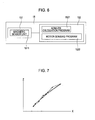
Fig. 6 is a block diagram schematically showing the structure of the electronic compass according to an embodiment of the present invention. -
Fig. 7 is a view for explaining the advantage of the present invention. - An embodiment of the present invention will be described referring to the drawings.
- The motion sensing executed by the motion sensing program according to the present invention functions in sensing the motion upon rotation of the magnetic sensor in a predetermined direction.
Figs. 1(a) to 1(c) show respective rotating directions of the magnetic sensor. Specifically,Fig. 1(a) shows the state where amagnetic sensor 1 is rotated horizontally (rotation with respect to the vertical axis).Fig. 1(b) shows the state where themagnetic sensor 1 is rotated longitudinally (rotation with respect to the horizontal axis).Fig. 1(c) shows the state where themagnetic sensor 1 is rotated laterally (rotation with respect to the horizontal axis). Each state shown inFigs. 1(b) and 1(c) represents the rotation with respect to the horizontal axis. In the case where the device having themagnetic sensor 1 installed therein (for example, mobile terminal device) has a substantially rectangular solid shape having long and short axes, the rotation shown inFig. 1(b) is the one with respect to the horizontal short axis. The rotation shown inFig. 1(c) is the one with respect to the horizontal long axis (longitudinal direction in the plane of the device surface). The horizontal direction of each rotation shown inFigs. 1(b) and 1(c) denotes the direction in the plane of the device surface having the magnetic sensor installed therein rather than the horizontal direction with respect to the ground surface. - When the magnetic sensor is rotated at 360° in each direction shown in
Figs. 1(a) to 1(c) , a substantially circular output is obtained in the output coordinate of any of the X-axis, Y-axis, and Z-axis. In case of the horizontal rotation shown inFig. 1(a) , the phase output at 90° is observed in the output coordinate of X-Y-axis while having the Z-axis output unchanged. In case of the longitudinal rotation shown inFig. 1(b) , the phase output at 90° is observed in the output coordinate of Y-Z-axis while having the X-axis output unchanged. In case of the lateral rotation shown inFig. 1(c) , the phase output at 90° is observed in the output coordinate of X-Z-axis while having the Y-axis output unchanged. - In the embodiment, the case in the lateral rotating direction (see
Fig. 1(c) ) will be described referring toFigs. 2(a) and 2(b) . In the motion sensing of this case, themagnetic sensor 1 is rotated in a reciprocating manner in the lateral direction at approximately 60° as shown inFigs. 2(a) and 2(b) . In this case, it is preferable to perform the reciprocated rotation at a relatively high speed (0.5 to 1 sec.) so as to be distinguished from the other operation. Selection between forward and backward directions allows the bi-directional sensing, that is, positive direction (Fig. 2(a) ) and negative direction (Fig. 2(b) ). - In the case where the electronic compass having the program installed therein is mounted on the mobile terminal, the lateral rotation is the motion intentionally performed by the user compared with the horizontal rotation. With the use of the motion switch, such rotation may be easily distinguished from the other operation, which is effective for suppressing the error.
- The principle of the motion sensing according to the present invention will be described.
- In the description, it is assumed that the magnetic sensor is of triaxial type, and the lateral direction is set as the predetermined rotating direction. The phase output at 90° is observed in the X-Z-axis output coordinate while having the Y-axis output unchanged.
- When the magnetic sensor is reciprocated in the lateral (positive) direction as shown in
Fig. 2(a) , outputs of the Z-axis and X-axis sensors are plotted into the circular track in the Z-X-axis output coordinate as shown inFig. 3(a) . When the magnetic sensor is reciprocated in the lateral (negative) direction as shown inFig. 2(b) , outputs of the Z-axis and X-axis sensors are plotted into the circular track as the Z-X-axis output coordinate as shown inFig. 3(b) . Actually, the outputs of the Z-axis and X-axis sensors are plotted around the circular track without being accurately plotted on the circular track owing to the hand shaking. Each of encircled numbers shown inFig. 3 denotes the plotting order. - The motion sensing program according to the present invention requires at least biaxial output of the magnetic sensor. The determination is made with respect to the motion sensing based on the specific biaxial output of the magnetic sensor, which rotates in the predetermined direction. The rotating direction may be identified when execution of the motion sensing is determined.
- The determination with respect to execution of the motion sensing is made upon the rotating operation of the aforementioned
magnetic sensor 1 when a distance A from a measurement starting point to the most distal measurement point therefrom in Z-X-axis output coordinate is equal to or larger than a predetermined value, and a distance B from a measurement point resulting from returning the magnetic sensor to the original position (returned to the rotation starting point) to the measurement starting point in Z-X-axis output coordinate is equal to or smaller than the predetermined value. Specifically, referring toFig. 3 , the determination is made on the basis of the distance A from the measurement starting point to the most distal measurement point (distance from themeasurement starting point 1 to the most distal measurement point 5), which is equal to or larger than the predetermined threshold value, and the distance B from themeasurement starting point 1 to the measurement point resulting from returning the magnetic sensor to the original position, that is, the measurement point among those obtained subsequent to the measurement of the most distal measurement point (measurement points 6 to 10) as being the closest (measurement point 9) to themeasurement starting point 1, which is equal to or smaller than the predetermined threshold value. The return of themagnetic sensor 1 to the original position represents that themagnetic sensor 1 is rotated in the predetermined direction, and then rotated in the opposite direction to be restored for the motion sensing. - The threshold determination with respect to the distance A may prevent the error of the motion sensing resulting from the micromotion, for example, hand shaking. The threshold determination with respect to the distance B may prevent the error of the motion sensing upon the mere rotating operation. The threshold value is set based on the magnitude of geomagnetism, and the radius of the circle formed in the X-Z-axis coordinate.
- In addition to the threshold determination, the determination may further be made with respect to execution of the motion sensing when the angle defined by a virtual line which connects a midpoint between the measurement starting point and the most distal measurement point to the measurement starting point, and a virtual line which connects the midpoint to the most distal measurement point is equal to or larger than the threshold value. That is, when the angle θ defined by the virtual line C which connects the midpoint (measurement point 7) to the measurement starting point, and the virtual line D which connects the midpoint to the most distal measurement point is equal to or larger than the threshold value, execution of the motion sensing may be determined. The threshold determination with respect to the angle θ may prevent the error of the motion sensing due to the external magnetic field, for example.
- The determination with respect to the rotating direction, that is, whether the rotating direction is positive or negative may be made based on the direction of the normal line of the virtual line C (the line from the
measurement starting point 1 to the midpoint 7), and the direction of the normal line of the virtual line D (the line from the midpoint 7 to the most distal measurement point 5). In other words, the normal vector is obtained by subjecting the vectors of the virtual lines C and D to the outer product. The rotating direction may be defined by the positive/negative Y-axis component of the obtained normal vector. Specifically, if the Y-axis component of the normal vector is positive, the rotation is in the positive direction, and if the Y-axis component of the normal vector is negative, the rotation is in the negative direction. - In the present invention, the motion sensing is executed in the case where the predetermined rotating operation of the magnetic sensor is performed within a predetermined period of time of approximately 0.5 to 1 second. When the predetermined rotating operation is performed after the elapse of the predetermined time period, the measurement value required for the motion sensing cannot be obtained. As a result, it may be determined as the other operation, and the motion sensing is not executed.
- The actual motion sensing will be described hereinafter.
Fig. 4 is a flowchart representing the routine for the motion sensing executed by the motion sensing program according to the embodiment of the present invention. - It is assumed that the output of the X-axis sensor is set to Xout, the output of the Z-axis sensor is set to Zout, and the required number of the measurement points (output plot) is set to Pcount. It is also assumed that the threshold value of the distance (distance A) between the measurement starting point to the most distal measurement point (turnaround point) when rotating the magnetic sensor laterally is set to Dth1, and the threshold value of the distance (distance B) between the measurement starting point to the measurement point resulting from returning the magnetic sensor is set to Dth2. The time period per each plot is set to 50 msec.
- Output values of X-axis and Z-axis are obtained until they are equal to or larger than Pcount. The obtained X-axis and Z-axis output values are used for providing the turnaround measurement point in the Z-X-axis output coordinate.
- It is assumed that outputs at the measurement starting points are set to Xout(0) and Zout(0), and outputs upon lateral rotation of the magnetic sensor are set to Xout(i) and Zout(i), the output change is calculated as the distance based on the following equation.

It is determined whether the relation of Dth1 ≤ D(i) is established, that is, whether the distance A is equal to or larger than the threshold value (ST11). If Dth1 ≤ D(i) is established, the measurement point corresponding to i is set as the most distal measurement point (turnaround measurement point) to store outputs of the corresponding X-axis and Z-axis. If i=k, the following equation (2) is established.
- The output change resulting from returning the magnetic sensor to the original position is calculated in the same way as described above. If i=end, the following equation (3) is established.

- It is determined whether the relation of Dth2 ≥ D(end) is established, that is, whether the distance B is equal to or smaller than the threshold value (ST12). If Dth2 ≥ D(end), the measurement point is set to the measurement end point to store outputs of the corresponding X and Z outputs. When the conditions are established by performing two threshold determinations, execution of the motion sensing is determined (ST13). Meanwhile, if any one of the conditions is not established by performing two threshold determinations, it is determined that the motion sensing is not executed (ST15).
- The direction of the output change of the lateral rotation is identified (ST14). In this case, the output at the midpoint between the measurement starting point and the turnaround measurement point is calculated. The X-axis and the Z-axis outputs at the midpoint are obtained using the following equations (4) and (5).


- The direction of the output change of the lateral rotation (rotating direction) is identified based on the normal vector derived from the normal lines of the virtual line from the measurement starting point to the midpoint (virtual line C shown in
Fig. 3 ) and the virtual line from the midpoint to the turnaround measurement point (virtual line D shown inFig. 3 ). Each vector of the virtual lines C and D will be calculated using the following equations (6) and (7).

- Each outer product of those vectors Cx, Cz, Dx and Dz is calculated to obtain the normal vector so as to determine whether the Y-axis component of the normal vector is positive or negative. The rotating direction is identified based on the determination result.
-
Fig. 5 schematically shows the structure of the mobile terminal device having the electronic compass according to the embodiment of the present invention installed therein. The mobile terminal device shown inFig. 5 is mainly formed of acontrol unit 11 for controlling the entire device, acommunication unit 12 for performing the wireless communication with other communication equipment, adisplay unit 13 for displaying various data, aninput unit 14 for inputting various data and operating the device, and anelectronic compass 15 for obtaining the azimuth. The motion sensing function according to the present invention allows theelectronic compass 15 to perform a switching operation, functioning as a motion switch for outputting to thecontrol unit 11 by detecting the motion. As theelectronic compass 15 serves as the motion switch, the mobile terminal device is capable of inputting the direction and switching the function without installing the additional sensors. It is assumed that the mobile terminal device includes the other devices normally installed in the mobile terminal device. -
Fig. 6 is a block diagram schematically showing the structure of the electronic compass according to the embodiment of the present invention. Theelectronic compass 15 shown inFig. 6 mainly includes acompass module 151 and acontrol unit 152. Thecompass module 151 includes amagnetic sensor unit 1511. Thecontrol unit 152 includes anazimuth calculation program 1521 for obtaining the azimuth based on the output of themagnetic sensor unit 1511, and amotion sensing program 1522 for executing the motion sensing based on the output of themagnetic sensor unit 1511. - The magnetic sensor of the
magnetic sensor unit 1511 in thecompass module 151 is designed to be adaptable to at least triaxial type for detecting magnetism. Any type of the sensor element may be used for forming the magnetic sensor. For example, a GMR (Giant MagnetoResistance) element, a GIG (Granular In Gap) element and a hall element may be employed as the sensor element. Thecompass module 151 includes a processing unit for applying voltage and magnetic field to themagnetic sensor unit 1511 and the processing unit for converting the analog signal from themagnetic sensor unit 1511 into the digital signal. - The
control unit 152 includes at least theazimuth calculation program 1521 and themotion sensing program 1522 as the driver software for driving thecompass module 151. The routine of theazimuth calculation program 1521 is not limited so long as the azimuth angle corresponding to the reference direction is obtained based on the magnetic detection information from thecompass module 151. - The
motion sensing program 1522 is executable by the computer for the motion sensing based on at least biaxial outputs of the magnetic sensor. The motion sensing program includes the steps of determining with respect to execution of the motion sensing based on the specific biaxial outputs of the magnetic sensor upon rotation of the magnetic sensor in the predetermined direction within the predetermined time period, and identifying the rotating direction when execution of the motion sensing is determined. - The motion sensing program allows identification of the rotating direction so as to execute the accurate motion sensing without requiring such processing as calibration.
In the motion sensing program, the distance in the output coordinate of X-axis and Z-axis among X-, Y-, and Z-axis is obtained, based on which the threshold determination is made to execute the motion sensing. This makes it possible to prevent the error of the motion sensing resulting from the micromotion such as the hand shaking, and the mere rotating operation. - In the technical concept of the present invention on the assumption that the magnetized object passes around the mobile terminal device, outputs are plotted on the linear track in the Z-X-axis coordinate as shown in
Fig. 7 . In the technology disclosed inPatent Document 1, it is determined whether the motion data are obtained based only on each comparison between the X-axis output and the predetermined threshold value, and between the Z-axis output and the predetermined threshold value. In the case as shown inFig. 7 , if the respective outputs of the X-axis and Z-axis exceed the predetermined threshold values, the motion data are obtained. It is highly likely to erroneously determine that the motion is effective in spite of being under the influence of the outer magnetic field. Meanwhile, according to the present invention, in the case as shown inFig. 7 , the angle θ becomes substantially 0, and does not exceed the predetermined threshold value. Accordingly, the operation is not determined as the motion. This makes it possible to prevent the error under the influence of the outer magnetic field. - The motion sensing according to the present invention may be executed in the leaked magnetic field by correction using the coil of the magnetic sensor. Even if the outer magnetic field changes, the motion sensing may be normally executed by the correction performed by the coil of the magnetic sensor, thus preventing the error.
- The present invention is applicable to the device without the electronic compass, for example, the mobile terminal device. In other words, it is applicable to the mobile terminal device provided with the magnetic sensor and the control unit having the motion sensing program for executing the motion sensing based on the magnetic sensor outputs, and the azimuth calculation program for obtaining the azimuth based on the magnetic sensor outputs for inputting the direction and switching the function through the motion sensing.
- The present invention may be modified into various forms without being limited to the aforementioned embodiment. In the embodiment, the magnetic sensor is rotated in the lateral direction. However, the present invention is not limited to the aforementioned rotating direction. It may be applicable to the horizontal and longitudinal rotating directions. In the embodiment, the motion sensing program is applied to the switching operation of the mobile terminal device. However, the motion sensing program according to the present invention is applicable to the switching operation of any other device. In the embodiment, the compass module and the control unit are separately structured in the electronic compass. In the present invention, the compass module and the control unit may be integrally formed. The present invention may be changed so long as it does not deviate from the scope thereof.
Claims (7)
- A motion sensing program executable by a computer for a motion sensing based on at least a biaxial output of a magnetic sensor, comprising the steps of:determining with respect to execution of the motion sensing based on a specific biaxial output of the magnetic sensor upon its rotation in a predetermined direction within a predetermined period of time; andidentifying a rotating direction of the magnetic sensor when the execution of the motion sensing is determined.
- The motion sensing program according to Claim 1, wherein in the step of determining with respect to execution of the motion sensing, the execution of the motion sensing is determined when a distance between a measurement starting point to a most distal measurement point from the measurement starting point in a coordinate of the specific biaxial output of the magnetic sensor is equal to or larger than a first predetermined value, and a distance between a measurement point resulting from substantially returning the magnetic sensor to a rotation starting position and the measurement starting point is equal to or smaller than a second predetermined value.
- The motion sensing program according to Claim 1, wherein in the step of identifying the rotating direction, the rotating direction is identified based on a direction of a normal vector defined by a virtual line which connects a midpoint with respect to the most distal measurement point to the measurement starting point, and a virtual line which connects the midpoint to the most distal measurement point.
- An electronic compass comprising:a compass module equipped with a magnetic sensor; anda control unit provided with the motion sensing program according to Claim 1 for executing a motion sensing based on an output of the magnetic sensor, and an azimuth calculation program for obtaining an azimuth based on the output of the magnetic sensor.
- A mobile terminal device comprising the electronic compass according to Claim 4 installed therein to obtain the azimuth and perform a switching operation.
- A mobile terminal device comprising:a magnetic sensor; anda control unit provided with the motion sensing program according to Claim 1 for executing the motion sensing based on an output of the magnetic sensor, and an azimuth calculation program for obtaining an azimuth based on the output of the magnetic sensor, wherein a switching operation is performed by the motor sensing.
- The mobile terminal device according to Claim 5, wherein the magnetic sensor is rotated in the predetermined direction with respect to an axis of a longitudinal direction in a plane of the device surface.
Applications Claiming Priority (2)
| Application Number | Priority Date | Filing Date | Title |
|---|---|---|---|
| JP2006329034 | 2006-12-06 | ||
| PCT/JP2007/073505 WO2008069241A1 (en) | 2006-12-06 | 2007-12-05 | Motion-sensing program and electronic compass using the same |
Publications (3)
| Publication Number | Publication Date |
|---|---|
| EP2098945A1 true EP2098945A1 (en) | 2009-09-09 |
| EP2098945A4 EP2098945A4 (en) | 2012-09-26 |
| EP2098945B1 EP2098945B1 (en) | 2016-07-20 |
Family
ID=39492123
Family Applications (1)
| Application Number | Title | Priority Date | Filing Date |
|---|---|---|---|
| EP07850129.3A Not-in-force EP2098945B1 (en) | 2006-12-06 | 2007-12-05 | Motion-sensing program and electronic compass using the same |
Country Status (4)
| Country | Link |
|---|---|
| US (1) | US8046189B2 (en) |
| EP (1) | EP2098945B1 (en) |
| JP (2) | JP5023073B2 (en) |
| WO (1) | WO2008069241A1 (en) |
Families Citing this family (14)
| Publication number | Priority date | Publication date | Assignee | Title |
|---|---|---|---|---|
| JP5128244B2 (en) * | 2007-11-05 | 2013-01-23 | 株式会社ミツトヨ | measuring device |
| JP5374287B2 (en) * | 2009-09-15 | 2013-12-25 | 任天堂株式会社 | Information processing program, information processing apparatus, information processing system, and information processing method |
| FR2950713A1 (en) * | 2009-09-29 | 2011-04-01 | Movea Sa | SYSTEM AND METHOD FOR RECOGNIZING GESTURES |
| CN103562791A (en) * | 2011-04-18 | 2014-02-05 | 眼见360股份有限公司 | Apparatus and method for panoramic video imaging with mobile computing devices |
| JP5497708B2 (en) * | 2011-08-31 | 2014-05-21 | 楽天株式会社 | Portable electronic device, control method for portable electronic device, program, and information storage medium |
| RU2012104711A (en) * | 2012-02-10 | 2013-08-20 | Корпорация "САМСУНГ ЭЛЕКТРОНИКС Ко., Лтд." | DETERMINATION OF MOTION STATUS |
| JP6171016B2 (en) * | 2012-09-14 | 2017-07-26 | ワイドヴァンテージ インク | Electric device that uses a magnetic field sensor to determine user input |
| JP2014066638A (en) | 2012-09-26 | 2014-04-17 | Lapis Semiconductor Co Ltd | Determination device, electronic apparatus, and determination method |
| JP6185656B2 (en) * | 2013-05-09 | 2017-08-23 | アマゾン テクノロジーズ インコーポレイテッド | Mobile device interface |
| US9342113B2 (en) * | 2013-07-18 | 2016-05-17 | Facebook, Inc. | Movement-triggered action for mobile device |
| JP5613314B1 (en) * | 2013-11-14 | 2014-10-22 | Jfeシステムズ株式会社 | Gesture detection device, gesture detection program, gesture recognition device, and gesture recognition program |
| CN104922902B (en) * | 2014-03-20 | 2018-08-31 | 联想(北京)有限公司 | A kind of joystick, electronic equipment, information processing method and device |
| JP6317411B2 (en) * | 2016-10-05 | 2018-04-25 | 株式会社小松製作所 | Construction machine management system |
| CN109618059A (en) * | 2019-01-03 | 2019-04-12 | 北京百度网讯科技有限公司 | Wake-up method and device for speech recognition function in mobile terminal |
Family Cites Families (12)
| Publication number | Priority date | Publication date | Assignee | Title |
|---|---|---|---|---|
| US5757360A (en) * | 1995-05-03 | 1998-05-26 | Mitsubishi Electric Information Technology Center America, Inc. | Hand held computer control device |
| JP2000065576A (en) * | 1998-08-21 | 2000-03-03 | Olympus Optical Co Ltd | Graphic display device |
| JP2002164990A (en) * | 2000-11-28 | 2002-06-07 | Kyocera Corp | Mobile communication terminal |
| JP2003005879A (en) * | 2001-06-19 | 2003-01-08 | Mitsubishi Electric Corp | Portable information terminal |
| US6651003B2 (en) * | 2001-07-30 | 2003-11-18 | Innovative Design Solutions, Inc. | Method of automatic continuous calibration for an electric compass |
| EP1314961B1 (en) * | 2001-11-22 | 2009-07-15 | Yamaha Corporation | Electronic apparatus |
| JP3733904B2 (en) * | 2001-12-27 | 2006-01-11 | ヤマハ株式会社 | Mobile phone device and control method thereof |
| JP4381161B2 (en) * | 2003-03-05 | 2009-12-09 | シチズンホールディングス株式会社 | Direction measuring device, direction measuring method, and direction measuring program |
| JP2007531113A (en) * | 2004-03-23 | 2007-11-01 | 富士通株式会社 | Identification of mobile device tilt and translational components |
| JP2006128789A (en) | 2004-10-26 | 2006-05-18 | Yamaha Corp | Mobile terminal |
| JP2006128788A (en) * | 2004-10-26 | 2006-05-18 | Yamaha Corp | Portable information terminal |
| JP4252555B2 (en) * | 2005-04-25 | 2009-04-08 | アルプス電気株式会社 | Tilt sensor and azimuth measuring device using the same |
-
2007
- 2007-12-05 WO PCT/JP2007/073505 patent/WO2008069241A1/en not_active Ceased
- 2007-12-05 EP EP07850129.3A patent/EP2098945B1/en not_active Not-in-force
- 2007-12-05 JP JP2008548312A patent/JP5023073B2/en not_active Expired - Fee Related
-
2009
- 2009-06-03 US US12/477,543 patent/US8046189B2/en not_active Expired - Fee Related
-
2012
- 2012-03-08 JP JP2012051226A patent/JP5194180B2/en not_active Expired - Fee Related
Also Published As
| Publication number | Publication date |
|---|---|
| US8046189B2 (en) | 2011-10-25 |
| EP2098945A4 (en) | 2012-09-26 |
| JP5194180B2 (en) | 2013-05-08 |
| JP5023073B2 (en) | 2012-09-12 |
| JPWO2008069241A1 (en) | 2010-03-18 |
| WO2008069241A1 (en) | 2008-06-12 |
| EP2098945B1 (en) | 2016-07-20 |
| JP2012123836A (en) | 2012-06-28 |
| US20090248352A1 (en) | 2009-10-01 |
Similar Documents
| Publication | Publication Date | Title |
|---|---|---|
| EP2098945B1 (en) | Motion-sensing program and electronic compass using the same | |
| KR102368230B1 (en) | Method of measuring angle between two bodies of foldable device and apparatus therefor | |
| US8494799B2 (en) | Dynamic compass calibration in a portable device | |
| JP6474128B2 (en) | Electronic equipment with geomagnetic and acceleration sensors | |
| US7870678B2 (en) | Hybrid sensor module and sensing method using the same | |
| EP1314961B1 (en) | Electronic apparatus | |
| EP0923762B1 (en) | Graphical display input device with magnetic sensors | |
| KR101103130B1 (en) | Magnetic data processing apparatus, methods and machine readable media | |
| KR101006812B1 (en) | Machine-readable media comprising magnetic data processing device, navigation device, magnetic data processing method and magnetic data processing program | |
| US11933933B2 (en) | Event detection method, event detection system, and non-transitory computer-readable recording medium | |
| JP4047335B2 (en) | Geomagnetic sensor and method for supporting depression angle detection function | |
| JPWO2014115848A1 (en) | Rotation information calculation method, rotation information calculation program, magnetic gyroscope and moving body | |
| JP5678748B2 (en) | Terminal device and geomagnetic environment determination program | |
| CN116583810A (en) | Input device, controller and error detection method | |
| EP4283435B1 (en) | Device and method for lid angle detection | |
| US8411030B2 (en) | Pointing and control device and method for a computer system | |
| JP2011185868A (en) | Azimuth detector | |
| KR101298845B1 (en) | Apparatus and method for calibrating azimuth magnetic sensor having object | |
| JP2009168678A (en) | Direction detection device and direction detection program | |
| JP5176537B2 (en) | Motion sensing device, motion sensing method, and motion sensing circuit | |
| JP3772806B2 (en) | Magnetic orientation detection method and magnetic orientation detection method | |
| JPH0875442A (en) | Simplified length measuring machine | |
| JP2006275523A (en) | Electronic azimuth device and recording medium | |
| JP2005043103A (en) | Magnetic compass | |
| JP2006284415A (en) | Position detecting device and camera |
Legal Events
| Date | Code | Title | Description |
|---|---|---|---|
| PUAI | Public reference made under article 153(3) epc to a published international application that has entered the european phase |
Free format text: ORIGINAL CODE: 0009012 |
|
| 17P | Request for examination filed |
Effective date: 20090624 |
|
| AK | Designated contracting states |
Kind code of ref document: A1 Designated state(s): AT BE BG CH CY CZ DE DK EE ES FI FR GB GR HU IE IS IT LI LT LU LV MC MT NL PL PT RO SE SI SK TR |
|
| DAX | Request for extension of the european patent (deleted) | ||
| A4 | Supplementary search report drawn up and despatched |
Effective date: 20120824 |
|
| RIC1 | Information provided on ipc code assigned before grant |
Ipc: G01C 17/28 20060101AFI20120820BHEP |
|
| 17Q | First examination report despatched |
Effective date: 20150122 |
|
| REG | Reference to a national code |
Ref country code: DE Ref legal event code: R079 Ref document number: 602007047119 Country of ref document: DE Free format text: PREVIOUS MAIN CLASS: G06F0003038000 Ipc: G06F0003034600 |
|
| RIC1 | Information provided on ipc code assigned before grant |
Ipc: G06F 3/0346 20130101AFI20151222BHEP Ipc: G01C 17/28 20060101ALI20151222BHEP |
|
| GRAP | Despatch of communication of intention to grant a patent |
Free format text: ORIGINAL CODE: EPIDOSNIGR1 |
|
| INTG | Intention to grant announced |
Effective date: 20160318 |
|
| GRAS | Grant fee paid |
Free format text: ORIGINAL CODE: EPIDOSNIGR3 |
|
| GRAA | (expected) grant |
Free format text: ORIGINAL CODE: 0009210 |
|
| AK | Designated contracting states |
Kind code of ref document: B1 Designated state(s): AT BE BG CH CY CZ DE DK EE ES FI FR GB GR HU IE IS IT LI LT LU LV MC MT NL PL PT RO SE SI SK TR |
|
| REG | Reference to a national code |
Ref country code: GB Ref legal event code: FG4D |
|
| REG | Reference to a national code |
Ref country code: CH Ref legal event code: EP |
|
| REG | Reference to a national code |
Ref country code: IE Ref legal event code: FG4D |
|
| REG | Reference to a national code |
Ref country code: AT Ref legal event code: REF Ref document number: 814577 Country of ref document: AT Kind code of ref document: T Effective date: 20160815 |
|
| REG | Reference to a national code |
Ref country code: DE Ref legal event code: R096 Ref document number: 602007047119 Country of ref document: DE |
|
| REG | Reference to a national code |
Ref country code: LT Ref legal event code: MG4D |
|
| REG | Reference to a national code |
Ref country code: NL Ref legal event code: MP Effective date: 20160720 |
|
| REG | Reference to a national code |
Ref country code: AT Ref legal event code: MK05 Ref document number: 814577 Country of ref document: AT Kind code of ref document: T Effective date: 20160720 |
|
| PG25 | Lapsed in a contracting state [announced via postgrant information from national office to epo] |
Ref country code: LT Free format text: LAPSE BECAUSE OF FAILURE TO SUBMIT A TRANSLATION OF THE DESCRIPTION OR TO PAY THE FEE WITHIN THE PRESCRIBED TIME-LIMIT Effective date: 20160720 Ref country code: NL Free format text: LAPSE BECAUSE OF FAILURE TO SUBMIT A TRANSLATION OF THE DESCRIPTION OR TO PAY THE FEE WITHIN THE PRESCRIBED TIME-LIMIT Effective date: 20160720 Ref country code: FI Free format text: LAPSE BECAUSE OF FAILURE TO SUBMIT A TRANSLATION OF THE DESCRIPTION OR TO PAY THE FEE WITHIN THE PRESCRIBED TIME-LIMIT Effective date: 20160720 Ref country code: IS Free format text: LAPSE BECAUSE OF FAILURE TO SUBMIT A TRANSLATION OF THE DESCRIPTION OR TO PAY THE FEE WITHIN THE PRESCRIBED TIME-LIMIT Effective date: 20161120 Ref country code: IT Free format text: LAPSE BECAUSE OF FAILURE TO SUBMIT A TRANSLATION OF THE DESCRIPTION OR TO PAY THE FEE WITHIN THE PRESCRIBED TIME-LIMIT Effective date: 20160720 |
|
| PG25 | Lapsed in a contracting state [announced via postgrant information from national office to epo] |
Ref country code: BE Free format text: LAPSE BECAUSE OF FAILURE TO SUBMIT A TRANSLATION OF THE DESCRIPTION OR TO PAY THE FEE WITHIN THE PRESCRIBED TIME-LIMIT Effective date: 20160720 Ref country code: GR Free format text: LAPSE BECAUSE OF FAILURE TO SUBMIT A TRANSLATION OF THE DESCRIPTION OR TO PAY THE FEE WITHIN THE PRESCRIBED TIME-LIMIT Effective date: 20161021 Ref country code: PL Free format text: LAPSE BECAUSE OF FAILURE TO SUBMIT A TRANSLATION OF THE DESCRIPTION OR TO PAY THE FEE WITHIN THE PRESCRIBED TIME-LIMIT Effective date: 20160720 Ref country code: PT Free format text: LAPSE BECAUSE OF FAILURE TO SUBMIT A TRANSLATION OF THE DESCRIPTION OR TO PAY THE FEE WITHIN THE PRESCRIBED TIME-LIMIT Effective date: 20161121 Ref country code: ES Free format text: LAPSE BECAUSE OF FAILURE TO SUBMIT A TRANSLATION OF THE DESCRIPTION OR TO PAY THE FEE WITHIN THE PRESCRIBED TIME-LIMIT Effective date: 20160720 Ref country code: AT Free format text: LAPSE BECAUSE OF FAILURE TO SUBMIT A TRANSLATION OF THE DESCRIPTION OR TO PAY THE FEE WITHIN THE PRESCRIBED TIME-LIMIT Effective date: 20160720 Ref country code: LV Free format text: LAPSE BECAUSE OF FAILURE TO SUBMIT A TRANSLATION OF THE DESCRIPTION OR TO PAY THE FEE WITHIN THE PRESCRIBED TIME-LIMIT Effective date: 20160720 Ref country code: SE Free format text: LAPSE BECAUSE OF FAILURE TO SUBMIT A TRANSLATION OF THE DESCRIPTION OR TO PAY THE FEE WITHIN THE PRESCRIBED TIME-LIMIT Effective date: 20160720 |
|
| REG | Reference to a national code |
Ref country code: DE Ref legal event code: R097 Ref document number: 602007047119 Country of ref document: DE |
|
| PG25 | Lapsed in a contracting state [announced via postgrant information from national office to epo] |
Ref country code: RO Free format text: LAPSE BECAUSE OF FAILURE TO SUBMIT A TRANSLATION OF THE DESCRIPTION OR TO PAY THE FEE WITHIN THE PRESCRIBED TIME-LIMIT Effective date: 20160720 Ref country code: EE Free format text: LAPSE BECAUSE OF FAILURE TO SUBMIT A TRANSLATION OF THE DESCRIPTION OR TO PAY THE FEE WITHIN THE PRESCRIBED TIME-LIMIT Effective date: 20160720 |
|
| PLBE | No opposition filed within time limit |
Free format text: ORIGINAL CODE: 0009261 |
|
| STAA | Information on the status of an ep patent application or granted ep patent |
Free format text: STATUS: NO OPPOSITION FILED WITHIN TIME LIMIT |
|
| PG25 | Lapsed in a contracting state [announced via postgrant information from national office to epo] |
Ref country code: BG Free format text: LAPSE BECAUSE OF FAILURE TO SUBMIT A TRANSLATION OF THE DESCRIPTION OR TO PAY THE FEE WITHIN THE PRESCRIBED TIME-LIMIT Effective date: 20161020 Ref country code: SK Free format text: LAPSE BECAUSE OF FAILURE TO SUBMIT A TRANSLATION OF THE DESCRIPTION OR TO PAY THE FEE WITHIN THE PRESCRIBED TIME-LIMIT Effective date: 20160720 Ref country code: CZ Free format text: LAPSE BECAUSE OF FAILURE TO SUBMIT A TRANSLATION OF THE DESCRIPTION OR TO PAY THE FEE WITHIN THE PRESCRIBED TIME-LIMIT Effective date: 20160720 Ref country code: DK Free format text: LAPSE BECAUSE OF FAILURE TO SUBMIT A TRANSLATION OF THE DESCRIPTION OR TO PAY THE FEE WITHIN THE PRESCRIBED TIME-LIMIT Effective date: 20160720 |
|
| 26N | No opposition filed |
Effective date: 20170421 |
|
| REG | Reference to a national code |
Ref country code: DE Ref legal event code: R082 Ref document number: 602007047119 Country of ref document: DE Representative=s name: SCHMITT-NILSON SCHRAUD WAIBEL WOHLFROM PATENTA, DE |
|
| REG | Reference to a national code |
Ref country code: CH Ref legal event code: PL |
|
| PG25 | Lapsed in a contracting state [announced via postgrant information from national office to epo] |
Ref country code: SI Free format text: LAPSE BECAUSE OF FAILURE TO SUBMIT A TRANSLATION OF THE DESCRIPTION OR TO PAY THE FEE WITHIN THE PRESCRIBED TIME-LIMIT Effective date: 20160720 |
|
| PG25 | Lapsed in a contracting state [announced via postgrant information from national office to epo] |
Ref country code: MC Free format text: LAPSE BECAUSE OF FAILURE TO SUBMIT A TRANSLATION OF THE DESCRIPTION OR TO PAY THE FEE WITHIN THE PRESCRIBED TIME-LIMIT Effective date: 20160720 |
|
| REG | Reference to a national code |
Ref country code: FR Ref legal event code: ST Effective date: 20170831 |
|
| REG | Reference to a national code |
Ref country code: IE Ref legal event code: MM4A |
|
| PG25 | Lapsed in a contracting state [announced via postgrant information from national office to epo] |
Ref country code: LI Free format text: LAPSE BECAUSE OF NON-PAYMENT OF DUE FEES Effective date: 20161231 Ref country code: CH Free format text: LAPSE BECAUSE OF NON-PAYMENT OF DUE FEES Effective date: 20161231 Ref country code: FR Free format text: LAPSE BECAUSE OF NON-PAYMENT OF DUE FEES Effective date: 20170102 Ref country code: LU Free format text: LAPSE BECAUSE OF NON-PAYMENT OF DUE FEES Effective date: 20161205 |
|
| PG25 | Lapsed in a contracting state [announced via postgrant information from national office to epo] |
Ref country code: IE Free format text: LAPSE BECAUSE OF NON-PAYMENT OF DUE FEES Effective date: 20161205 |
|
| PG25 | Lapsed in a contracting state [announced via postgrant information from national office to epo] |
Ref country code: CY Free format text: LAPSE BECAUSE OF FAILURE TO SUBMIT A TRANSLATION OF THE DESCRIPTION OR TO PAY THE FEE WITHIN THE PRESCRIBED TIME-LIMIT Effective date: 20160720 Ref country code: HU Free format text: LAPSE BECAUSE OF FAILURE TO SUBMIT A TRANSLATION OF THE DESCRIPTION OR TO PAY THE FEE WITHIN THE PRESCRIBED TIME-LIMIT; INVALID AB INITIO Effective date: 20071205 |
|
| PG25 | Lapsed in a contracting state [announced via postgrant information from national office to epo] |
Ref country code: TR Free format text: LAPSE BECAUSE OF FAILURE TO SUBMIT A TRANSLATION OF THE DESCRIPTION OR TO PAY THE FEE WITHIN THE PRESCRIBED TIME-LIMIT Effective date: 20160720 |
|
| PG25 | Lapsed in a contracting state [announced via postgrant information from national office to epo] |
Ref country code: MT Free format text: LAPSE BECAUSE OF NON-PAYMENT OF DUE FEES Effective date: 20161205 |
|
| PGFP | Annual fee paid to national office [announced via postgrant information from national office to epo] |
Ref country code: DE Payment date: 20181210 Year of fee payment: 12 |
|
| REG | Reference to a national code |
Ref country code: DE Ref legal event code: R082 Ref document number: 602007047119 Country of ref document: DE Representative=s name: SCHMITT-NILSON SCHRAUD WAIBEL WOHLFROM PATENTA, DE Ref country code: DE Ref legal event code: R081 Ref document number: 602007047119 Country of ref document: DE Owner name: ALPS ALPINE CO., LTD., JP Free format text: FORMER OWNER: ALPS ELECTRIC CO., LTD, TOKYO, JP |
|
| PGFP | Annual fee paid to national office [announced via postgrant information from national office to epo] |
Ref country code: GB Payment date: 20181218 Year of fee payment: 12 |
|
| REG | Reference to a national code |
Ref country code: DE Ref legal event code: R119 Ref document number: 602007047119 Country of ref document: DE |
|
| GBPC | Gb: european patent ceased through non-payment of renewal fee |
Effective date: 20191205 |
|
| PG25 | Lapsed in a contracting state [announced via postgrant information from national office to epo] |
Ref country code: DE Free format text: LAPSE BECAUSE OF NON-PAYMENT OF DUE FEES Effective date: 20200701 Ref country code: GB Free format text: LAPSE BECAUSE OF NON-PAYMENT OF DUE FEES Effective date: 20191205 |