EP2098745B1 - Verfahren zur Ermittlung des Tastpunktes einer Kupplung durch einen Lernprozess - Google Patents
Verfahren zur Ermittlung des Tastpunktes einer Kupplung durch einen Lernprozess Download PDFInfo
- Publication number
- EP2098745B1 EP2098745B1 EP09154155A EP09154155A EP2098745B1 EP 2098745 B1 EP2098745 B1 EP 2098745B1 EP 09154155 A EP09154155 A EP 09154155A EP 09154155 A EP09154155 A EP 09154155A EP 2098745 B1 EP2098745 B1 EP 2098745B1
- Authority
- EP
- European Patent Office
- Prior art keywords
- clutch
- electric machine
- torque
- vehicle
- speed
- Prior art date
- Legal status (The legal status is an assumption and is not a legal conclusion. Google has not performed a legal analysis and makes no representation as to the accuracy of the status listed.)
- Not-in-force
Links
Images

Classifications
-
- F—MECHANICAL ENGINEERING; LIGHTING; HEATING; WEAPONS; BLASTING
- F16—ENGINEERING ELEMENTS AND UNITS; GENERAL MEASURES FOR PRODUCING AND MAINTAINING EFFECTIVE FUNCTIONING OF MACHINES OR INSTALLATIONS; THERMAL INSULATION IN GENERAL
- F16D—COUPLINGS FOR TRANSMITTING ROTATION; CLUTCHES; BRAKES
- F16D48/00—External control of clutches
- F16D48/06—Control by electric or electronic means, e.g. of fluid pressure
-
- F—MECHANICAL ENGINEERING; LIGHTING; HEATING; WEAPONS; BLASTING
- F16—ENGINEERING ELEMENTS AND UNITS; GENERAL MEASURES FOR PRODUCING AND MAINTAINING EFFECTIVE FUNCTIONING OF MACHINES OR INSTALLATIONS; THERMAL INSULATION IN GENERAL
- F16D—COUPLINGS FOR TRANSMITTING ROTATION; CLUTCHES; BRAKES
- F16D2500/00—External control of clutches by electric or electronic means
- F16D2500/10—System to be controlled
- F16D2500/104—Clutch
- F16D2500/10443—Clutch type
- F16D2500/1045—Friction clutch
-
- F—MECHANICAL ENGINEERING; LIGHTING; HEATING; WEAPONS; BLASTING
- F16—ENGINEERING ELEMENTS AND UNITS; GENERAL MEASURES FOR PRODUCING AND MAINTAINING EFFECTIVE FUNCTIONING OF MACHINES OR INSTALLATIONS; THERMAL INSULATION IN GENERAL
- F16D—COUPLINGS FOR TRANSMITTING ROTATION; CLUTCHES; BRAKES
- F16D2500/00—External control of clutches by electric or electronic means
- F16D2500/10—System to be controlled
- F16D2500/106—Engine
- F16D2500/1066—Hybrid
-
- F—MECHANICAL ENGINEERING; LIGHTING; HEATING; WEAPONS; BLASTING
- F16—ENGINEERING ELEMENTS AND UNITS; GENERAL MEASURES FOR PRODUCING AND MAINTAINING EFFECTIVE FUNCTIONING OF MACHINES OR INSTALLATIONS; THERMAL INSULATION IN GENERAL
- F16D—COUPLINGS FOR TRANSMITTING ROTATION; CLUTCHES; BRAKES
- F16D2500/00—External control of clutches by electric or electronic means
- F16D2500/30—Signal inputs
- F16D2500/304—Signal inputs from the clutch
- F16D2500/3041—Signal inputs from the clutch from the input shaft
- F16D2500/30412—Torque of the input shaft
-
- F—MECHANICAL ENGINEERING; LIGHTING; HEATING; WEAPONS; BLASTING
- F16—ENGINEERING ELEMENTS AND UNITS; GENERAL MEASURES FOR PRODUCING AND MAINTAINING EFFECTIVE FUNCTIONING OF MACHINES OR INSTALLATIONS; THERMAL INSULATION IN GENERAL
- F16D—COUPLINGS FOR TRANSMITTING ROTATION; CLUTCHES; BRAKES
- F16D2500/00—External control of clutches by electric or electronic means
- F16D2500/30—Signal inputs
- F16D2500/304—Signal inputs from the clutch
- F16D2500/3042—Signal inputs from the clutch from the output shaft
- F16D2500/30421—Torque of the output shaft
- F16D2500/30423—Signal detecting the transmission of zero torque
-
- F—MECHANICAL ENGINEERING; LIGHTING; HEATING; WEAPONS; BLASTING
- F16—ENGINEERING ELEMENTS AND UNITS; GENERAL MEASURES FOR PRODUCING AND MAINTAINING EFFECTIVE FUNCTIONING OF MACHINES OR INSTALLATIONS; THERMAL INSULATION IN GENERAL
- F16D—COUPLINGS FOR TRANSMITTING ROTATION; CLUTCHES; BRAKES
- F16D2500/00—External control of clutches by electric or electronic means
- F16D2500/30—Signal inputs
- F16D2500/306—Signal inputs from the engine
- F16D2500/3065—Torque of the engine
-
- F—MECHANICAL ENGINEERING; LIGHTING; HEATING; WEAPONS; BLASTING
- F16—ENGINEERING ELEMENTS AND UNITS; GENERAL MEASURES FOR PRODUCING AND MAINTAINING EFFECTIVE FUNCTIONING OF MACHINES OR INSTALLATIONS; THERMAL INSULATION IN GENERAL
- F16D—COUPLINGS FOR TRANSMITTING ROTATION; CLUTCHES; BRAKES
- F16D2500/00—External control of clutches by electric or electronic means
- F16D2500/50—Problem to be solved by the control system
- F16D2500/502—Relating the clutch
- F16D2500/50245—Calibration or recalibration of the clutch touch-point
- F16D2500/50251—During operation
-
- F—MECHANICAL ENGINEERING; LIGHTING; HEATING; WEAPONS; BLASTING
- F16—ENGINEERING ELEMENTS AND UNITS; GENERAL MEASURES FOR PRODUCING AND MAINTAINING EFFECTIVE FUNCTIONING OF MACHINES OR INSTALLATIONS; THERMAL INSULATION IN GENERAL
- F16D—COUPLINGS FOR TRANSMITTING ROTATION; CLUTCHES; BRAKES
- F16D2500/00—External control of clutches by electric or electronic means
- F16D2500/50—Problem to be solved by the control system
- F16D2500/502—Relating the clutch
- F16D2500/50245—Calibration or recalibration of the clutch touch-point
- F16D2500/50266—Way of detection
- F16D2500/50275—Estimation of the displacement of the clutch touch-point due to the modification of relevant parameters, e.g. temperature, wear
-
- F—MECHANICAL ENGINEERING; LIGHTING; HEATING; WEAPONS; BLASTING
- F16—ENGINEERING ELEMENTS AND UNITS; GENERAL MEASURES FOR PRODUCING AND MAINTAINING EFFECTIVE FUNCTIONING OF MACHINES OR INSTALLATIONS; THERMAL INSULATION IN GENERAL
- F16D—COUPLINGS FOR TRANSMITTING ROTATION; CLUTCHES; BRAKES
- F16D2500/00—External control of clutches by electric or electronic means
- F16D2500/70—Details about the implementation of the control system
- F16D2500/704—Output parameters from the control unit; Target parameters to be controlled
- F16D2500/70402—Actuator parameters
- F16D2500/7041—Position
-
- Y—GENERAL TAGGING OF NEW TECHNOLOGICAL DEVELOPMENTS; GENERAL TAGGING OF CROSS-SECTIONAL TECHNOLOGIES SPANNING OVER SEVERAL SECTIONS OF THE IPC; TECHNICAL SUBJECTS COVERED BY FORMER USPC CROSS-REFERENCE ART COLLECTIONS [XRACs] AND DIGESTS
- Y02—TECHNOLOGIES OR APPLICATIONS FOR MITIGATION OR ADAPTATION AGAINST CLIMATE CHANGE
- Y02T—CLIMATE CHANGE MITIGATION TECHNOLOGIES RELATED TO TRANSPORTATION
- Y02T10/00—Road transport of goods or passengers
- Y02T10/60—Other road transportation technologies with climate change mitigation effect
- Y02T10/62—Hybrid vehicles
Definitions
- the invention relates to a method for determining the licking point of a clutch by learning on a hybrid vehicle.
- the invention aims in particular to optimize the point of licking of the clutch ensuring the coupling and decoupling between a heat engine and an electric machine.
- the invention finds a particularly advantageous application in the field of motor vehicles, including hybrid type vehicles.
- a hybrid type vehicle uses two types of energy, thermal energy and electrical energy, the combination of which guarantees the traction of the vehicle, while optimizing the fuel efficiency, and thus reducing the fuel consumption of the vehicle and the same blow the pollution.
- Parallel type hybrid vehicles which comprises a heat engine and an electric machine connected to each other by the introduction of a clutch.
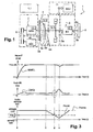
- a hybrid hybrid vehicle architecture is illustrated by the figure 1 which shows a transmission device 1 comprising a set of members including a heat engine 2, a clutch 3, an electric machine 4, a gearbox 5, and wheels 6 which form a pull chain.
- the clutch 3 comprises a first disc 3a and a second disc 3b clutch.
- the first clutch disk 3a is connected to a shaft 2a of the heat engine 2.
- the second clutch disk 3b is connected to a shaft 4a of the electric machine 4.
- the shaft 4a of the electric machine 4 and a shaft 5c of the wheels 6 are respectively connected to an inlet 5a and an outlet 5b of the gearbox 5.
- the heat engine 1 is started by means of an independent starting system 8 which is connected to it by means of a belt.
- the transmission device 1 is capable of operating in two modes of operation. In an electric mode, only the electric machine 4 provides torque to the wheels. The clutch 3 then remains open so that the shaft 2a of the heat engine 2 and the shaft 4a of the electric machine 4 are uncoupled from each other. In this mode, the electrical machine takes energy from the energy storage system 7 such as a battery, and operates in motor mode.
- the energy storage system 7 such as a battery
- the shaft 5c of the wheels 6 is driven by both the heat engine 2 and the electric machine 4.
- the clutch 3 is then closed, so that the shaft 2a of the heat engine and the shaft 5c wheels 6 are coupled together.
- the electric machine 4 operates either in engine mode to transmit torque to the wheels 6 in parallel with the torque supplied by the heat engine in order to adjust the torque applied to the wheels, or in generator mode in order to recharge the battery 7, the machine being then driven by the engine 2.
- Each member 2 to 5 is controlled by a clean control computer 2.1, 3.1, 4.1, 5.1.
- These control computers 2.1, 3.1, 4.1, 5.1 are themselves controlled by a single computer 1.1 said supervision.
- This supervision computer 1.1 is able to synchronize the actuations of the various members 2 to 5 in order to meet the will of the driver of the vehicle.
- the set of control computers 2.1, 3.1, 4.1, 5.1 are able to control the vehicle power train (increase or decrease the speed of the engine and / or the electric machine) and select a vehicle running mode ( urban mode, economy mode, non-polluting mode, sports mode ...), according to the different life situations and the state of the vehicle.
- the supervision computer is also able to coordinate all the transient phases and determine the operation of the electric machine and the heat engine in order to optimize the fuel consumption and the depollution.
- a licking point makes it possible to reset the transfer function of the position of a clutch actuator relative to the torque and thus to control the torque transmitted by the clutch.
- Clutch licking point means the point on the most advanced clutch curve in the direction of the clutch, for which torque is still not transmitted. The purpose of this transfer function is to increase in reliability and consistency on the transmission of the clutch torque when starting the vehicle or a gear ratio change.
- the learning of the licking point does not take into account the previously mentioned dynamic phenomena such as wear or dispersions following thermal phenomena. Indeed, learning the point of licking is at the beginning of life of the hybrid vehicle but throughout the life of the vehicle, the licking point moves according to the wear of the various elements constituting the clutch, It is therefore necessary to readjust said licking point when needed.
- the present invention aims to overcome the disadvantages of the techniques described above.
- the invention proposes a method for automatically determining the licking point of a clutch system by learning.
- the invention allows learning and registration of the licking point of the clutch system without requiring the start of the engine during the start of the hybrid vehicle.
- the invention allows a learning speed because of the dynamics of the electric machine in regulation regime. It also allows constant control of a couple of the clutch system and therefore of the hybrid drivetrain over the life of the vehicle.
- Each hybrid vehicle comprises a device 1 for transmitting torque to the wheels 6 comprising members 2-5 and 7-8 as illustrated in FIG. figure 1 .
- Each of the members 2-5 is respectively associated with a control computer 2.1, 3.1, 4.1, 5.1 and at least one sensor (not shown).
- a control computer 2.1, 3.1, 4.1, 5.1 is intended to drive the member 2-5 with which it is associated.
- Each control computer 2.1, 3.1, 4.1, 5.1 is able to receive data from the sensors of the respective member 2-5 and 7-8 associated. All the computers 2.1, 3.1, 4.1, 5.1 are controlled by a supervision computer 1.1 whose task is to harmonize the functioning of the organs 2-5, so as to be able to make decisions and synchronize the actions of the computers 2.1, 3.1 , 4.1, 5.1 to meet the will of a driver.
- the control computers 2.1, 3.1, 4.1, 5.1 and the supervision computer 1.1 each include, in particular, a program memory, a data memory connected both to a microprocessor.
- actions are provided to the computers 1.1, 2.1, 3.1, 4.1, 5.1 and the programs they execute, it means that these actions are controlled by the microprocessors of the computers comprising said programs, said microprocessors being then controlled by the instruction codes stored in the computers memories.
- These instruction codes make it possible to control the organs connected to the computers and thus to carry out the action undertaken.
- the figure 2 is an example of a functional diagram of the method according to the invention.
- This diagram shows a preliminary step 11 in which the supervision computer 1.1 performs steps of verification of the initial conditions, according to the method of the invention.
- the supervision computer 1.1 sends an interrogation request on the operating state of the heat engine 2 to the control computer 2.1 associated with this engine 2.
- Said control computer 2.1 determines by means of Engine 2 sensors, if the latter is stopped.
- control computer 2.1 of the engine 2 returns, for example, zero to the supervision computer 1.1.
- the supervision computer 1.1 sends an interrogation request on the operating state of the clutch 3 to the control computer 3.1 associated with this clutch 3.
- Said control computer 3.1 determines by means of sensors position (not shown) of the clutch 3, if the latter is open. If the clutch is open, the control computer 3.1 of the clutch 3 returns, for example, one to the supervision computer 1.1.
- the supervision computer 1.1 sends a request for interrogation on the operating state of the gearbox 5, with Compact Guided Mechanical Transmission (MCP), to the control computer 5.1 associated with this box. speed 5.
- MCP Compact Guided Mechanical Transmission
- Said control computer 5.1 determines by means of sensors of the gearbox, if the latter is in neutral.
- step 11 when all the aforementioned conditions are met, the implementation of the method can begin.
- step 13 regulation of the speed of the electric machine is performed. Indeed, the control computer of the electric machine controls an increase in the torque of the electric machine so that the speed of said electric machine is equal to the speed reference.
- step 14 a test loop is applied to the method to determine if the speed of the electric machine is equal to the set point that has been given. If the speed of the electric machine is equal to the setpoint that has been given, then step 15 is applied. Otherwise, step 13 is repeated.
- step 15 a gradual closing of the clutch is performed in order to transmit a resistive torque to the electric machine.
- This resistive torque is intended to disturb the speed control of the electric machine performed in step 13.
- step 16 the speed control responds to the disturbance by increasing the torque of the electric machine in return for the resistive torque due to the closure of the clutch.
- a test loop (not shown) is applied to the method to determine if the torque delta of the electrical machine is greater than a threshold. This threshold is calibrated. If the torque Delta of the electric machine is greater than the predefined threshold, then step 17 is applied. In the opposite case, the increase in torque of step 16 is repeated.
- step 17 the position of the clutch actuator (for example at the level of a concentric stop) is determined and then memorized at an instant "t" where the delta has been detected during the execution of step 16.
- the determination of the position of the actuator of the clutch is returned to the control computer associated with it by a position sensor.
- step 18 from the position of the clutch actuator defined in step 17, the licking point of the clutch is determined under the conditions of wear and current temperature.
- step 19 the clutch is opened to finish the learning procedure.
- the figure 3 shows chronograms of observable signals on the various organs 2 to 5 of the device of the figure 1 during the implementation of the method of the invention. These signals are observable when a learning procedure is requested.
- the figure 3 shows the observable speed signal of the electric machine, the torque signal of the electric machine and the signal corresponding to the position of the clutch actuator.
- the figure 3 also shows the evolution over time of the speed reference of the electric machine and the reference of the position of the actuator of the clutch.
- the signals defined above are emitted respectively by a speed sensor of the electric machine, a torque sensor or estimator of the electric machine and a position sensor of the actuator of the clutch.
- Each signal is captured and processed by a control computer associated with the organ on which it depends. All the processed signals are collected by the supervision computer and analyzed by the latter in order to optimize the control of the various components of the vehicle.
- the vehicle At time t0, the vehicle is at a standstill.
- the electric machine 3 and the heat engine 1 both have a zero speed, the box is in neutral and the clutch is open.
- the hybrid vehicle is started and the conditions are required to respond to a learning sequence of the licking point.
- the speed of the electric machine increases exponentially, so that at time t1, the speed is stabilized around a value CRMEL corresponding to a set point of the electric machine. Furthermore, between time t0 and t1, the torque signal CMEL of the electric machine 3 increases linearly to stabilize around a torque value of the electric machine 3.
- the supervision computer sends a slow closing order and progressive clutch.
- the close-up computer of the clutch drives the actuator clutch to follow this instruction.
- the speed of the electric machine is always stabilized around the set value given by CRMEL.
- the torque of the electric machine is also stabilized around a torque value.
- the clutch is opened again after the time t3.
- This re-opening of the clutch causes a decrease in the torque of the electric machine.
- This re-opening also causes a return of the signal of the speed of the electric machine around the CRMEL setpoint.
Landscapes
- Engineering & Computer Science (AREA)
- General Engineering & Computer Science (AREA)
- Physics & Mathematics (AREA)
- Fluid Mechanics (AREA)
- Mechanical Engineering (AREA)
- Hydraulic Clutches, Magnetic Clutches, Fluid Clutches, And Fluid Joints (AREA)
- Hybrid Electric Vehicles (AREA)
- Control Of Vehicle Engines Or Engines For Specific Uses (AREA)
- Control Of Driving Devices And Active Controlling Of Vehicle (AREA)
Claims (9)
- Verfahren zum Bestimmen des Schleifpunkts einer Kupplung eines Fahrzeugs des hybriden Typs beim Starten oder Gangwechseln, wobei das Fahrzeug eine Zugkette aufweist, darunter einen Verbrennungsmotor und eine Elektromaschine, die miteinander über die Kupplung derart gekuppelt sind, dass die Kombination des Moments des Verbrennungsmotors und des Moments der Elektromaschine das Indrehungversetzen der Welle der Räder des Fahrzeugs bewirkt, dadurch gekennzeichnet, dass es die folgenden Schritte aufweist:A - Prüfen (11), dass der Verbrennungsmotor stillsteht und dass die Kupplung offen ist,B - Regeln (13) der Drehzahl der Elektromaschine,C - langsames Schließen (15) der Kupplung,D - Erhöhen (16) des Moments der Elektromaschine,E - Erfassen (16) eines Momentunterschieds der Elektromaschine,F - Bestimmen und dann Speichern (17) der Position des Kupplungsstellantriebs im Augenblick dieses Erfassens,G - Bestimmen (18) des Schleifpunkts der Kupplung.
- Verfahren nach Anspruch 1, dadurch gekennzeichnet, dass die Kupplung im Schritt A maximal offen ist und während einer bestimmten Dauer maximal offen bleibt.
- Verfahren nach Anspruch 2, dadurch gekennzeichnet, dass im Schritt B die Regelung (13) der Drehzahl der Elektromaschine zu einem gegebenen Sollwert erfolgt.
- Verfahren nach Anspruch 3, dadurch gekennzeichnet, dass im Schritt C das Schließen (15) der Kupplung erfolgt, sobald die Drehzahl der Elektromaschine stabilisiert ist, um Widerstandsmoment auf die Elektromaschine zu übertragen und dadurch ihre Drehzahlregelung zu stören.
- Verfahren nach Anspruch 4, dadurch gekennzeichnet, dass im Schritt D die Erhöhung (16) des Moments der Elektromaschine erfolgt, um das Widerstandsmoment der Kupplung auszugleichen.
- Verfahren nach Anspruch 5, dadurch gekennzeichnet, dass im Schritt E das Erfassen (16) eines Momentunterschieds der Elektromaschine für Momente oberhalb eines Schwellenwerts erfolgt.
- Verfahren nach Anspruch 6, dadurch gekennzeichnet, dass der Schwellenwert kalibrierbar ist.
- Verfahren nach Anspruch 7, dadurch gekennzeichnet, dass im Schritt F das Bestimmen (17) der Position des Kupplungsstellantriebs durch einen Lagesensor erfolgt.
- Verfahren nach Anspruch 8, dadurch gekennzeichnet, dass die Kupplung wieder geöffnet wird (19), sobald der Schleifpunkt bestimmt ist (18).
Applications Claiming Priority (1)
| Application Number | Priority Date | Filing Date | Title |
|---|---|---|---|
| FR0851366A FR2928186B1 (fr) | 2008-03-03 | 2008-03-03 | Procede de determination automatique du point de lechage d'un embrayage par apprentissage |
Publications (2)
| Publication Number | Publication Date |
|---|---|
| EP2098745A1 EP2098745A1 (de) | 2009-09-09 |
| EP2098745B1 true EP2098745B1 (de) | 2010-12-22 |
Family
ID=39830173
Family Applications (1)
| Application Number | Title | Priority Date | Filing Date |
|---|---|---|---|
| EP09154155A Not-in-force EP2098745B1 (de) | 2008-03-03 | 2009-03-02 | Verfahren zur Ermittlung des Tastpunktes einer Kupplung durch einen Lernprozess |
Country Status (4)
| Country | Link |
|---|---|
| EP (1) | EP2098745B1 (de) |
| AT (1) | ATE492740T1 (de) |
| DE (1) | DE602009000446D1 (de) |
| FR (1) | FR2928186B1 (de) |
Families Citing this family (5)
| Publication number | Priority date | Publication date | Assignee | Title |
|---|---|---|---|---|
| DE102009053885B4 (de) * | 2009-11-20 | 2015-10-29 | Getrag Getriebe- Und Zahnradfabrik Hermann Hagenmeyer Gmbh & Cie Kg | Verfahren zur Kisspointadaption |
| FR3003320B1 (fr) * | 2013-03-13 | 2016-02-19 | Peugeot Citroen Automobiles Sa | Procede et dispositif de controle du pre-positionnement temporaire d'un embrayage d'une boite de vitesses robotisee d'un vehicule |
| FR3008957B1 (fr) * | 2013-07-23 | 2015-08-14 | Eurocopter France | Installation motrice trimoteur regulee pour un aeronef a voilure tournante |
| FR3106175B1 (fr) * | 2020-01-14 | 2022-06-24 | Psa Automobiles Sa | Procede de sur-verrouillage d'un embrayage d'une chaine de traction de vehicule hybride lors d'un changement de rapport de vitesse |
| CN116624525B (zh) * | 2023-06-07 | 2025-12-30 | 中国第一汽车股份有限公司 | 一种离合器半结合点位置自学习方法、装置及车辆 |
Family Cites Families (4)
| Publication number | Priority date | Publication date | Assignee | Title |
|---|---|---|---|---|
| US6991585B2 (en) * | 2004-05-04 | 2006-01-31 | Ford Global Technologies, Llc | Torsional isolation of a convertless automatic transmission through slip control of friction clutch |
| US7347803B2 (en) * | 2004-10-27 | 2008-03-25 | Aisin Aw Co., Ltd. | Drive apparatus for hybrid vehicle and control method and control device thereof |
| DE102006005470A1 (de) * | 2006-02-07 | 2007-08-09 | Zf Friedrichshafen Ag | Verfahren zum Betreiben eines Parallelhybridantriebsstranges eines Fahrzeugs |
| JP4396661B2 (ja) * | 2006-05-26 | 2010-01-13 | 日産自動車株式会社 | ハイブリッド車両のクラッチ締結制御装置 |
-
2008
- 2008-03-03 FR FR0851366A patent/FR2928186B1/fr not_active Expired - Fee Related
-
2009
- 2009-03-02 AT AT09154155T patent/ATE492740T1/de not_active IP Right Cessation
- 2009-03-02 EP EP09154155A patent/EP2098745B1/de not_active Not-in-force
- 2009-03-02 DE DE602009000446T patent/DE602009000446D1/de active Active
Also Published As
| Publication number | Publication date |
|---|---|
| DE602009000446D1 (de) | 2011-02-03 |
| FR2928186A1 (fr) | 2009-09-04 |
| ATE492740T1 (de) | 2011-01-15 |
| FR2928186B1 (fr) | 2010-04-30 |
| EP2098745A1 (de) | 2009-09-09 |
Similar Documents
| Publication | Publication Date | Title |
|---|---|---|
| EP2107264B1 (de) | Verfahren zur automatischen Bestimmung des Schleifpunktes einer Kupplung durch Lernen | |
| FR2882698A1 (fr) | Procede de decollage rapide d'un vehicule hybride | |
| EP2098745A1 (de) | Verfahren zur Ermittlung des Tastpunktes einer Kupplung durch einen Lernprozess | |
| CN105189231A (zh) | 用于检测车辆离合器接触点的方法和系统 | |
| EP2937554B1 (de) | Diagnoseverfahren zum Erkennen eines Schlupfes des Aggregate-Antriebsriemens eines Antriebsstranges | |
| EP2107263B1 (de) | Verfahren zur automatischen Bestimmung des Schleifpunktes einer Kupplung durch Lernen | |
| WO2013060971A1 (fr) | Procede de repartition de couples entre des trains avant et arriere d'un vehicule hybride | |
| FR2658564A1 (fr) | Dispositif pour le controle unifie du moteur et de la transmission automatique dans un vehicule automobile. | |
| FR3058696B1 (fr) | Dispositif de pilotage d'une boite de vitesses robotisee pour vehicule automobile a propulsion hybride | |
| EP1792106B1 (de) | Verfahren zur steuerung im multibedienungsmodus eines automatikgetriebes für ein kraftfahrzeug, besonders für leerlaufbetrieb mit nichtangezogener bremse und dazugehörige vorrichtung | |
| FR2995956A1 (fr) | Procede de correction de la position d'un plateau de pression dans un embrayage. | |
| EP1791715B1 (de) | Verfahren zur steuerung des mehrbetriebsmodus eines automatikgetriebes für ein kraftfahrzeug, im besonderen für leerlaufbetrieb mit angezogener bremse und dazugehörige vorrichtung | |
| FR2920848A1 (fr) | Procede et dispositif de commande d'un embrayage par determination du couple transmis pour un vehicule automobile. | |
| FR2955818A1 (fr) | Procede de changement de rapport ameliore pour vehicule a moteur thermique muni d'un turbocompresseur | |
| FR2914382A1 (fr) | Dispositif d'embrayage | |
| FR3013295A1 (fr) | Procede de commande d'un alternateur associe a un moteur thermique de vehicule automobile | |
| FR2946604A3 (fr) | Procede et dispositif de controle d'un groupe motopropulseur de vehicule automobile. | |
| WO2008050054A2 (fr) | Procede et dispositif de controle de la charge electrique d'un element tampon d'energie dans une transmission infiniment variable | |
| FR3144088A1 (fr) | Procédé d’optimisation de la récupération énergétique pour un véhicule automobile hybride parallèle à boite de vitesses manuelle | |
| WO2016058891A1 (fr) | Procede et systeme de pilotage d'un embrayage | |
| FR2806976A1 (fr) | Procede de commande d'un moteur de vehicule automobile lors d'un changement de vitesse | |
| FR2863326A1 (fr) | Module de supervision de la transmission | |
| FR2867241A1 (fr) | Procede et systeme simplifies de commande de la fermeture d'un embrayage pilote, et support d'enregistrement d'informations pour leur mise en oeuvre | |
| FR2877706A1 (fr) | Procede et dispositif de commande de transmissions a convertisseur de couple hydraulique | |
| WO2005000651A1 (fr) | Dispositif de ralentissement pour vehicule automobile |
Legal Events
| Date | Code | Title | Description |
|---|---|---|---|
| PUAI | Public reference made under article 153(3) epc to a published international application that has entered the european phase |
Free format text: ORIGINAL CODE: 0009012 |
|
| AK | Designated contracting states |
Kind code of ref document: A1 Designated state(s): AT BE BG CH CY CZ DE DK EE ES FI FR GB GR HR HU IE IS IT LI LT LU LV MC MK MT NL NO PL PT RO SE SI SK TR |
|
| AX | Request for extension of the european patent |
Extension state: AL BA RS |
|
| 17P | Request for examination filed |
Effective date: 20100225 |
|
| 17Q | First examination report despatched |
Effective date: 20100323 |
|
| AKX | Designation fees paid |
Designated state(s): AT BE BG CH CY CZ DE DK EE ES FI FR GB GR HR HU IE IS IT LI LT LU LV MC MK MT NL NO PL PT RO SE SI SK TR |
|
| GRAP | Despatch of communication of intention to grant a patent |
Free format text: ORIGINAL CODE: EPIDOSNIGR1 |
|
| GRAS | Grant fee paid |
Free format text: ORIGINAL CODE: EPIDOSNIGR3 |
|
| GRAA | (expected) grant |
Free format text: ORIGINAL CODE: 0009210 |
|
| AK | Designated contracting states |
Kind code of ref document: B1 Designated state(s): AT BE BG CH CY CZ DE DK EE ES FI FR GB GR HR HU IE IS IT LI LT LU LV MC MK MT NL NO PL PT RO SE SI SK TR |
|
| REG | Reference to a national code |
Ref country code: GB Ref legal event code: FG4D Free format text: NOT ENGLISH |
|
| REG | Reference to a national code |
Ref country code: CH Ref legal event code: EP |
|
| REG | Reference to a national code |
Ref country code: IE Ref legal event code: FG4D |
|
| REF | Corresponds to: |
Ref document number: 602009000446 Country of ref document: DE Date of ref document: 20110203 Kind code of ref document: P |
|
| REG | Reference to a national code |
Ref country code: DE Ref legal event code: R096 Ref document number: 602009000446 Country of ref document: DE Effective date: 20110203 |
|
| REG | Reference to a national code |
Ref country code: NL Ref legal event code: VDEP Effective date: 20101222 |
|
| PG25 | Lapsed in a contracting state [announced via postgrant information from national office to epo] |
Ref country code: LT Free format text: LAPSE BECAUSE OF FAILURE TO SUBMIT A TRANSLATION OF THE DESCRIPTION OR TO PAY THE FEE WITHIN THE PRESCRIBED TIME-LIMIT Effective date: 20101222 |
|
| LTIE | Lt: invalidation of european patent or patent extension |
Effective date: 20101222 |
|
| PG25 | Lapsed in a contracting state [announced via postgrant information from national office to epo] |
Ref country code: CY Free format text: LAPSE BECAUSE OF FAILURE TO SUBMIT A TRANSLATION OF THE DESCRIPTION OR TO PAY THE FEE WITHIN THE PRESCRIBED TIME-LIMIT Effective date: 20101222 Ref country code: BG Free format text: LAPSE BECAUSE OF FAILURE TO SUBMIT A TRANSLATION OF THE DESCRIPTION OR TO PAY THE FEE WITHIN THE PRESCRIBED TIME-LIMIT Effective date: 20110322 Ref country code: FI Free format text: LAPSE BECAUSE OF FAILURE TO SUBMIT A TRANSLATION OF THE DESCRIPTION OR TO PAY THE FEE WITHIN THE PRESCRIBED TIME-LIMIT Effective date: 20101222 Ref country code: SE Free format text: LAPSE BECAUSE OF FAILURE TO SUBMIT A TRANSLATION OF THE DESCRIPTION OR TO PAY THE FEE WITHIN THE PRESCRIBED TIME-LIMIT Effective date: 20101222 Ref country code: AT Free format text: LAPSE BECAUSE OF FAILURE TO SUBMIT A TRANSLATION OF THE DESCRIPTION OR TO PAY THE FEE WITHIN THE PRESCRIBED TIME-LIMIT Effective date: 20101222 Ref country code: LV Free format text: LAPSE BECAUSE OF FAILURE TO SUBMIT A TRANSLATION OF THE DESCRIPTION OR TO PAY THE FEE WITHIN THE PRESCRIBED TIME-LIMIT Effective date: 20101222 Ref country code: SI Free format text: LAPSE BECAUSE OF FAILURE TO SUBMIT A TRANSLATION OF THE DESCRIPTION OR TO PAY THE FEE WITHIN THE PRESCRIBED TIME-LIMIT Effective date: 20101222 Ref country code: HR Free format text: LAPSE BECAUSE OF FAILURE TO SUBMIT A TRANSLATION OF THE DESCRIPTION OR TO PAY THE FEE WITHIN THE PRESCRIBED TIME-LIMIT Effective date: 20101222 |
|
| REG | Reference to a national code |
Ref country code: IE Ref legal event code: FD4D |
|
| PG25 | Lapsed in a contracting state [announced via postgrant information from national office to epo] |
Ref country code: GR Free format text: LAPSE BECAUSE OF FAILURE TO SUBMIT A TRANSLATION OF THE DESCRIPTION OR TO PAY THE FEE WITHIN THE PRESCRIBED TIME-LIMIT Effective date: 20110323 Ref country code: PT Free format text: LAPSE BECAUSE OF FAILURE TO SUBMIT A TRANSLATION OF THE DESCRIPTION OR TO PAY THE FEE WITHIN THE PRESCRIBED TIME-LIMIT Effective date: 20110422 Ref country code: CZ Free format text: LAPSE BECAUSE OF FAILURE TO SUBMIT A TRANSLATION OF THE DESCRIPTION OR TO PAY THE FEE WITHIN THE PRESCRIBED TIME-LIMIT Effective date: 20101222 Ref country code: IS Free format text: LAPSE BECAUSE OF FAILURE TO SUBMIT A TRANSLATION OF THE DESCRIPTION OR TO PAY THE FEE WITHIN THE PRESCRIBED TIME-LIMIT Effective date: 20110422 Ref country code: EE Free format text: LAPSE BECAUSE OF FAILURE TO SUBMIT A TRANSLATION OF THE DESCRIPTION OR TO PAY THE FEE WITHIN THE PRESCRIBED TIME-LIMIT Effective date: 20101222 Ref country code: ES Free format text: LAPSE BECAUSE OF FAILURE TO SUBMIT A TRANSLATION OF THE DESCRIPTION OR TO PAY THE FEE WITHIN THE PRESCRIBED TIME-LIMIT Effective date: 20110402 Ref country code: NO Free format text: LAPSE BECAUSE OF FAILURE TO SUBMIT A TRANSLATION OF THE DESCRIPTION OR TO PAY THE FEE WITHIN THE PRESCRIBED TIME-LIMIT Effective date: 20110322 |
|
| REG | Reference to a national code |
Ref country code: GB Ref legal event code: 746 Effective date: 20110801 |
|
| REG | Reference to a national code |
Ref country code: DE Ref legal event code: R084 Ref document number: 602009000446 Country of ref document: DE |
|
| PG25 | Lapsed in a contracting state [announced via postgrant information from national office to epo] |
Ref country code: RO Free format text: LAPSE BECAUSE OF FAILURE TO SUBMIT A TRANSLATION OF THE DESCRIPTION OR TO PAY THE FEE WITHIN THE PRESCRIBED TIME-LIMIT Effective date: 20101222 Ref country code: SK Free format text: LAPSE BECAUSE OF FAILURE TO SUBMIT A TRANSLATION OF THE DESCRIPTION OR TO PAY THE FEE WITHIN THE PRESCRIBED TIME-LIMIT Effective date: 20101222 Ref country code: PL Free format text: LAPSE BECAUSE OF FAILURE TO SUBMIT A TRANSLATION OF THE DESCRIPTION OR TO PAY THE FEE WITHIN THE PRESCRIBED TIME-LIMIT Effective date: 20101222 Ref country code: NL Free format text: LAPSE BECAUSE OF FAILURE TO SUBMIT A TRANSLATION OF THE DESCRIPTION OR TO PAY THE FEE WITHIN THE PRESCRIBED TIME-LIMIT Effective date: 20101222 |
|
| BERE | Be: lapsed |
Owner name: PEUGEOT CITROEN AUTOMOBILES S.A. Effective date: 20110331 |
|
| REG | Reference to a national code |
Ref country code: DE Ref legal event code: R084 Ref document number: 602009000446 Country of ref document: DE Effective date: 20110725 |
|
| PLBE | No opposition filed within time limit |
Free format text: ORIGINAL CODE: 0009261 |
|
| STAA | Information on the status of an ep patent application or granted ep patent |
Free format text: STATUS: NO OPPOSITION FILED WITHIN TIME LIMIT |
|
| PG25 | Lapsed in a contracting state [announced via postgrant information from national office to epo] |
Ref country code: DK Free format text: LAPSE BECAUSE OF FAILURE TO SUBMIT A TRANSLATION OF THE DESCRIPTION OR TO PAY THE FEE WITHIN THE PRESCRIBED TIME-LIMIT Effective date: 20101222 Ref country code: MC Free format text: LAPSE BECAUSE OF NON-PAYMENT OF DUE FEES Effective date: 20110331 Ref country code: IE Free format text: LAPSE BECAUSE OF FAILURE TO SUBMIT A TRANSLATION OF THE DESCRIPTION OR TO PAY THE FEE WITHIN THE PRESCRIBED TIME-LIMIT Effective date: 20101222 |
|
| 26N | No opposition filed |
Effective date: 20110923 |
|
| PG25 | Lapsed in a contracting state [announced via postgrant information from national office to epo] |
Ref country code: MT Free format text: LAPSE BECAUSE OF FAILURE TO SUBMIT A TRANSLATION OF THE DESCRIPTION OR TO PAY THE FEE WITHIN THE PRESCRIBED TIME-LIMIT Effective date: 20101222 Ref country code: IT Free format text: LAPSE BECAUSE OF FAILURE TO SUBMIT A TRANSLATION OF THE DESCRIPTION OR TO PAY THE FEE WITHIN THE PRESCRIBED TIME-LIMIT Effective date: 20101222 Ref country code: BE Free format text: LAPSE BECAUSE OF NON-PAYMENT OF DUE FEES Effective date: 20110331 |
|
| REG | Reference to a national code |
Ref country code: DE Ref legal event code: R097 Ref document number: 602009000446 Country of ref document: DE Effective date: 20110923 |
|
| PG25 | Lapsed in a contracting state [announced via postgrant information from national office to epo] |
Ref country code: MK Free format text: LAPSE BECAUSE OF FAILURE TO SUBMIT A TRANSLATION OF THE DESCRIPTION OR TO PAY THE FEE WITHIN THE PRESCRIBED TIME-LIMIT Effective date: 20101222 |
|
| PG25 | Lapsed in a contracting state [announced via postgrant information from national office to epo] |
Ref country code: LU Free format text: LAPSE BECAUSE OF NON-PAYMENT OF DUE FEES Effective date: 20110302 |
|
| PG25 | Lapsed in a contracting state [announced via postgrant information from national office to epo] |
Ref country code: TR Free format text: LAPSE BECAUSE OF FAILURE TO SUBMIT A TRANSLATION OF THE DESCRIPTION OR TO PAY THE FEE WITHIN THE PRESCRIBED TIME-LIMIT Effective date: 20101222 |
|
| PG25 | Lapsed in a contracting state [announced via postgrant information from national office to epo] |
Ref country code: HU Free format text: LAPSE BECAUSE OF FAILURE TO SUBMIT A TRANSLATION OF THE DESCRIPTION OR TO PAY THE FEE WITHIN THE PRESCRIBED TIME-LIMIT Effective date: 20101222 |
|
| REG | Reference to a national code |
Ref country code: CH Ref legal event code: PL |
|
| PG25 | Lapsed in a contracting state [announced via postgrant information from national office to epo] |
Ref country code: CH Free format text: LAPSE BECAUSE OF NON-PAYMENT OF DUE FEES Effective date: 20130331 Ref country code: LI Free format text: LAPSE BECAUSE OF NON-PAYMENT OF DUE FEES Effective date: 20130331 |
|
| PGFP | Annual fee paid to national office [announced via postgrant information from national office to epo] |
Ref country code: DE Payment date: 20140220 Year of fee payment: 6 |
|
| PGFP | Annual fee paid to national office [announced via postgrant information from national office to epo] |
Ref country code: GB Payment date: 20140226 Year of fee payment: 6 |
|
| PGFP | Annual fee paid to national office [announced via postgrant information from national office to epo] |
Ref country code: FR Payment date: 20140328 Year of fee payment: 6 |
|
| REG | Reference to a national code |
Ref country code: DE Ref legal event code: R119 Ref document number: 602009000446 Country of ref document: DE |
|
| GBPC | Gb: european patent ceased through non-payment of renewal fee |
Effective date: 20150302 |
|
| REG | Reference to a national code |
Ref country code: FR Ref legal event code: ST Effective date: 20151130 |
|
| PG25 | Lapsed in a contracting state [announced via postgrant information from national office to epo] |
Ref country code: GB Free format text: LAPSE BECAUSE OF NON-PAYMENT OF DUE FEES Effective date: 20150302 Ref country code: DE Free format text: LAPSE BECAUSE OF NON-PAYMENT OF DUE FEES Effective date: 20151001 |
|
| PG25 | Lapsed in a contracting state [announced via postgrant information from national office to epo] |
Ref country code: FR Free format text: LAPSE BECAUSE OF NON-PAYMENT OF DUE FEES Effective date: 20150331 |