EP2098689A2 - Blade attachment retention device - Google Patents
Blade attachment retention device Download PDFInfo
- Publication number
- EP2098689A2 EP2098689A2 EP09250325A EP09250325A EP2098689A2 EP 2098689 A2 EP2098689 A2 EP 2098689A2 EP 09250325 A EP09250325 A EP 09250325A EP 09250325 A EP09250325 A EP 09250325A EP 2098689 A2 EP2098689 A2 EP 2098689A2
- Authority
- EP
- European Patent Office
- Prior art keywords
- annulus filler
- filler
- rotor disc
- annulus
- connector
- Prior art date
- Legal status (The legal status is an assumption and is not a legal conclusion. Google has not performed a legal analysis and makes no representation as to the accuracy of the status listed.)
- Granted
Links
- 230000014759 maintenance of location Effects 0.000 title description 15
- 239000000945 filler Substances 0.000 claims abstract description 119
- 230000008878 coupling Effects 0.000 claims description 4
- 238000010168 coupling process Methods 0.000 claims description 4
- 238000005859 coupling reaction Methods 0.000 claims description 4
- 230000005484 gravity Effects 0.000 description 2
- 229910000838 Al alloy Inorganic materials 0.000 description 1
- 230000000295 complement effect Effects 0.000 description 1
- 230000002939 deleterious effect Effects 0.000 description 1
- 238000005242 forging Methods 0.000 description 1
- 239000003562 lightweight material Substances 0.000 description 1
- 238000000034 method Methods 0.000 description 1
- 238000012986 modification Methods 0.000 description 1
- 230000004048 modification Effects 0.000 description 1
- 230000000717 retained effect Effects 0.000 description 1
- 230000002459 sustained effect Effects 0.000 description 1
Images


Classifications
-
- F—MECHANICAL ENGINEERING; LIGHTING; HEATING; WEAPONS; BLASTING
- F01—MACHINES OR ENGINES IN GENERAL; ENGINE PLANTS IN GENERAL; STEAM ENGINES
- F01D—NON-POSITIVE DISPLACEMENT MACHINES OR ENGINES, e.g. STEAM TURBINES
- F01D21/00—Shutting-down of machines or engines, e.g. in emergency; Regulating, controlling, or safety means not otherwise provided for
- F01D21/04—Shutting-down of machines or engines, e.g. in emergency; Regulating, controlling, or safety means not otherwise provided for responsive to undesired position of rotor relative to stator or to breaking-off of a part of the rotor, e.g. indicating such position
- F01D21/045—Shutting-down of machines or engines, e.g. in emergency; Regulating, controlling, or safety means not otherwise provided for responsive to undesired position of rotor relative to stator or to breaking-off of a part of the rotor, e.g. indicating such position special arrangements in stators or in rotors dealing with breaking-off of part of rotor
-
- F—MECHANICAL ENGINEERING; LIGHTING; HEATING; WEAPONS; BLASTING
- F01—MACHINES OR ENGINES IN GENERAL; ENGINE PLANTS IN GENERAL; STEAM ENGINES
- F01D—NON-POSITIVE DISPLACEMENT MACHINES OR ENGINES, e.g. STEAM TURBINES
- F01D11/00—Preventing or minimising internal leakage of working-fluid, e.g. between stages
- F01D11/005—Sealing means between non relatively rotating elements
- F01D11/006—Sealing the gap between rotor blades or blades and rotor
- F01D11/008—Sealing the gap between rotor blades or blades and rotor by spacer elements between the blades, e.g. independent interblade platforms
-
- F—MECHANICAL ENGINEERING; LIGHTING; HEATING; WEAPONS; BLASTING
- F01—MACHINES OR ENGINES IN GENERAL; ENGINE PLANTS IN GENERAL; STEAM ENGINES
- F01D—NON-POSITIVE DISPLACEMENT MACHINES OR ENGINES, e.g. STEAM TURBINES
- F01D5/00—Blades; Blade-carrying members; Heating, heat-insulating, cooling or antivibration means on the blades or the members
- F01D5/30—Fixing blades to rotors; Blade roots ; Blade spacers
- F01D5/32—Locking, e.g. by final locking blades or keys
- F01D5/326—Locking of axial insertion type blades by other means
-
- F—MECHANICAL ENGINEERING; LIGHTING; HEATING; WEAPONS; BLASTING
- F05—INDEXING SCHEMES RELATING TO ENGINES OR PUMPS IN VARIOUS SUBCLASSES OF CLASSES F01-F04
- F05D—INDEXING SCHEME FOR ASPECTS RELATING TO NON-POSITIVE-DISPLACEMENT MACHINES OR ENGINES, GAS-TURBINES OR JET-PROPULSION PLANTS
- F05D2250/00—Geometry
- F05D2250/40—Movement of components
- F05D2250/41—Movement of components with one degree of freedom
- F05D2250/411—Movement of components with one degree of freedom in rotation
Definitions
- the present invention relates to annulus fillers for bridging gaps between adjacent blades of a gas turbine engine stage.
- a compressor rotor stage in a gas turbine engine comprises a plurality of radially extending blades mounted on a disc.
- the blades are mounted on the disc by inserting a root portion of the blade in a complementary retention groove in the outer face of the disc periphery.
- annulus fillers can be used to bridge the spaces between adjacent blades.
- a seal between the annulus fillers and the adjacent fan blades is also provided by resilient strips bonded to the annulus fillers adjacent the fan blades.
- Annulus fillers of this type are commonly used in the fan stage of gas turbine engines.
- the fillers may be manufactured from relatively lightweight materials and, in the event of damage, may be replaced independently of the blades.
- annulus fillers with features for removably attaching them to the rotor disc.
- An annulus filler may be provided with axially spaced hook members, the hook members sliding into engagement with respective parts of the rotor disc and/or a component located axially behind the rotor assembly, for example a rear fan air seal.
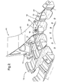
- Figure 1 shows an example of such an annulus filler viewed from the side.
- the upper surface or lid 2 of the annulus filler 1 bridges the gap between two adjacent fan blades (not shown) and defines the inner wall of the flow annulus of a fan stage.
- the annulus filler 1 is mounted on a fan disc (not shown) by two hook members 3 and 4, respectively towards the forward and rearward ends of the annulus filler.
- annulus filler is also attached to a front support ring (not shown) at axial retention flange 5, the support ring itself attaching to the front of the fan disc.
- the two opposed side faces of the annulus filler are provided with respective seal strips (not shown) and confront the aerofoil surfaces of the adjacent fan blades.
- the annulus filler is a machined aluminium alloy forging.
- Retention flange 5 carries an interference fit pin 6 which inserts into a corresponding hole formed in the front support ring.
- Annulus fillers of this type are self-loading in that, as a rotating component, the majority of forces on the filler are generated by its own mass. However, under birdstrike or blade-off conditions, a blade can deflect at the annulus filler position and apply a pushing force to the filler in a lateral, circumferential direction.
- the hook contact.faces of the annulus filler shown in Figure 1 and of the fan disc to which, in use, it is mounted are curved around a radius of the disc so that under the force of a deflecting blade the filler will tend to rotate at the hook members around the centre line of the engine.
- An object of the invention is to provide an annulus filler which is less likely to sustain damage under lateral loading from an adjacent blade.
- a first aspect of the present invention provides an annulus filler for mounting to a rotor disc of a gas turbine engine and for bridging the gap between two adjacent blades attached to the rotor disc, the annulus filler defining an airflow surface for air being drawn through the engine, wherein the annulus filler has:
- the or each primary connector is configured to allow circumferential sliding motion of the annulus filler relative to the rotor disc at that primary connector.
- the or each primary connector may include a hook extending radially inwards for engagement with a correspondingly-shaped hook on the radially outer face of the rotor disc.
- the hook contact faces can be curved around a radius of the engine.
- the or each primary connector resists, in use, motion of the annulus filler relative to the rotor disc in the opposite axial direction to the first axial direction.
- motion of the annulus filler in the first axial direction may not be resisted by the or each primary connector.
- the primary connector includes a rearward-facing hook
- the hook can resist motion of the annulus filler relative to the rotor disc in the rearward axial direction, but not in the forward axial direction.
- the secondary connector is configured to allow circumferential sliding motion of the annulus filler relative to the rotor disc at the secondary connector.
- the secondary connector may be formed at an axial end of the annulus filler, and preferably, for ease of access, it is formed at the axial end corresponding to the side of the rotor disc from which an operator mounts the filler.
- fan disc annulus fillers are generally inserted into position from the forward side of the fan disc, whereby, for such a disc, the secondary connector is conveniently formed at the axially forward end of the filler.
- the secondary connector comprises a pin and slot coupling, the slot extending in a circumferential direction, and the pin extending through the slot in an axial direction and being movable along the slot to allow rotation of the filler around the engine centre line at the secondary connector.
- the secondary connector may be configured to allow the rotation at the secondary connector only within predetermined limits.
- the predetermined limits may be defined by the ends of the slot, which prevent further movement of the pin in the direction of the slot.
- the slot of the pin and slot coupling may be formed in the annulus filler.
- the slot of the pin and slot coupling may be formed in the annulus filler.
- a retention flange extending from the filler.
- the pin may be provided by the shaft of a fixing bolt which, in use, resists the motion of the annulus filler relative to the rotor disc in the first axial direction.
- the annulus filler bridges the gap between adjacent fan blades.
- a further aspect of the present invention provides a stage for a gas turbine engine having:
- FIG 2 shows a front perspective view of an annulus filler 11 according to the present invention. Like the conventional filler of Figure 1 , it has a lid 12 for bridging the gap between two adjacent fan blades (not shown) and defining the inner wall of the flow annulus of a fan stage.
- the filler 11 is mounted on a fan disc 10 by forward and rearward hooks 13, 14. These form the primary connectors for the filler, joining to correspondingly-shaped hooks on the outer radial surface of the disc to resist, in use, centrifugal forces on the filler and motion of the filler in the rearwards axial direction.
- the contacting faces of the hooks 13, 14 and correspondingly-shaped hooks of the disc 10 are curved around radii to the engine centre-line, allowing the filler to slide circumferentially at the contacting faces when the filler is exposed to lateral forces from the adjacent blades.
- the filler 11 is also attached to a front fixing plate 16 of the disc 10 at axial retention flange 15 by fixing bolt 17 which extends through a slot 18 in the retention flange and a hole 19 in the fixing plate.
- the retention flange and fixing bolt form a secondary connector for the filler which, in use, resists motion of the filler in the forwards axial direction.
- the filler 11 To mount the filler 11 to the disc, the filler is inserted into the space between two adjacent blades along a forward to rearward direction, until hooks 13, 14 engage with their respective correspondingly-shaped hooks on the disc.
- the circumferential position of the filler is adjusted so that its centre of gravity is on a radius from the engine centre-line passing through the bolt 17.
- flange 15 and plate 16 have respective holes 23, 24 which, when aligned, indicate the correct circumferential position.
- a close fit pin is inserted through the alignment holes 23, 24. Fixing bolt 17 is then inserted through slot 18 and hole 19. The bolt 17 is tightened and the close fit pin removed.
- the close fit pin (not shown) is preferably hollow or shaped so that it is easily broken.
- a frangible close fit pin is preferred so that in the event it is inadvertently left in the alignment holes 23,24 it is not deleterious to the operation of the annulus filler.
- the filler centre of gravity is not aligned during mounting, at high rotational speeds the filler will tend to rotate about the engine centre-line until alignment is achieved.
- other means of aligning the filler and the rotor such as alignment datums or surfaces, can be used instead of holes 23, 24.
- an assembly jig may ensure alignment.
- the filler can be self-aligning under rotation, which avoids the need for the adjustment step of the mounting procedure.
- Figure 3a is a close-up view of the retention flange 15 and the fixing bolt 17, and Figure 3b is the same close-up view but without the fixing bolt to better show the slot 18 and the hole 19.
- Figure 4 shows the retention flange 15 and fixing bolt 17 in cross-section.
- the head 17a of the bolt 17 sits on a spreader washer 20 to distribute the load at the bolt head.
- the interfaces between the flange 15 and plate 16, and between the flange 15 and the washer 20 are lubricated to reduce friction at these interfaces when the filler rotates.
- a swaged nut 21 retained at hole 19 is threaded to the shaft 17b of the bolt 17 to tighten the bolt.
- the shaft 17b of the bolt 17 serves as a pin extending though the slot 18.
- the shaft can move along the slot until it impinges on the end of the slot, thereby allowing the filler to rotate by a limited amount at the secondary connector.
- This rotation which occurs with the rotation at the primary connectors, can prevent potentially damaging twisting forces from being applied to the filler.
- the slot length can therefore be configured to correspond to the predicted amount of deflection that the blades experience under birdstrike or blade-off events.
- Figures 5a and b show the filler 11 and adjacent blades 22 in respectively their assembly positions and rotated positions after such an event. To better show the relative positions of the slot 18 and hole 19, the fixing bolt 17 is omitted.
Landscapes
- Engineering & Computer Science (AREA)
- Mechanical Engineering (AREA)
- General Engineering & Computer Science (AREA)
- Structures Of Non-Positive Displacement Pumps (AREA)
- Turbine Rotor Nozzle Sealing (AREA)
Abstract
Description
- The present invention relates to annulus fillers for bridging gaps between adjacent blades of a gas turbine engine stage.
- Conventionally, a compressor rotor stage in a gas turbine engine comprises a plurality of radially extending blades mounted on a disc. The blades are mounted on the disc by inserting a root portion of the blade in a complementary retention groove in the outer face of the disc periphery. To ensure a smooth radially inner surface for air to flow over as it passes through the stage, annulus fillers can be used to bridge the spaces between adjacent blades. Typically, a seal between the annulus fillers and the adjacent fan blades is also provided by resilient strips bonded to the annulus fillers adjacent the fan blades.
- Annulus fillers of this type are commonly used in the fan stage of gas turbine engines. The fillers may be manufactured from relatively lightweight materials and, in the event of damage, may be replaced independently of the blades.
- It is known to provide annulus fillers with features for removably attaching them to the rotor disc. An annulus filler may be provided with axially spaced hook members, the hook members sliding into engagement with respective parts of the rotor disc and/or a component located axially behind the rotor assembly, for example a rear fan air seal.
Figure 1 shows an example of such an annulus filler viewed from the side. In use, the upper surface orlid 2 of the annulus filler 1 bridges the gap between two adjacent fan blades (not shown) and defines the inner wall of the flow annulus of a fan stage. The annulus filler 1 is mounted on a fan disc (not shown) by twohook members 3 and 4, respectively towards the forward and rearward ends of the annulus filler. It is also attached to a front support ring (not shown) ataxial retention flange 5, the support ring itself attaching to the front of the fan disc. The two opposed side faces of the annulus filler are provided with respective seal strips (not shown) and confront the aerofoil surfaces of the adjacent fan blades. Typically the annulus filler is a machined aluminium alloy forging. -
Retention flange 5 carries an interference fit pin 6 which inserts into a corresponding hole formed in the front support ring.Flange 5, abutting the support ring, resists motion of the annulus filler in the forward axial direction, while pin 6 helps to ensure that the annulus filler occupies the correct angular position on the disc. - Annulus fillers of this type are self-loading in that, as a rotating component, the majority of forces on the filler are generated by its own mass. However, under birdstrike or blade-off conditions, a blade can deflect at the annulus filler position and apply a pushing force to the filler in a lateral, circumferential direction. The hook contact.faces of the annulus filler shown in
Figure 1 and of the fan disc to which, in use, it is mounted are curved around a radius of the disc so that under the force of a deflecting blade the filler will tend to rotate at the hook members around the centre line of the engine. - However, as the
axial retention flange 5 is pinned, and sometimes also bolted, to the front support ring, this rotation leads to twisting of the annulus filler. The twisting can cause damage or failure of the filler, typically at thelid 2 between the forward hook member and the retention flange. An object of the invention is to provide an annulus filler which is less likely to sustain damage under lateral loading from an adjacent blade. - A first aspect of the present invention provides an annulus filler for mounting to a rotor disc of a gas turbine engine and for bridging the gap between two adjacent blades attached to the rotor disc, the annulus filler defining an airflow surface for air being drawn through the engine, wherein the annulus filler has:
- one or more primary connectors for connecting the annulus filler to the rotor disc, and for resisting, in use, centrifugal forces on the annulus filler, the or each primary connector allowing rotation of the annulus filler around the centre line of the engine relative to the rotor disc at that primary connector; and
- a secondary connector for connecting the annulus filler to the rotor disc and for resisting, in use, motion of the annulus filler relative to the rotor disc in a first axial direction, the secondary connector allowing rotation of the annulus filler around the centre line of the engine relative to the rotor disc at the secondary connector.
- Thus, by having a secondary connector that allows rotation of the annulus filler around the centre line at the secondary connector, it is possible to eliminate or reduce twisting of the filler under lateral loading from an adjacent blade. Eliminating or reducing such twisting in turn can reduce the amount of damage sustained by the filler.
- Preferably, the or each primary connector is configured to allow circumferential sliding motion of the annulus filler relative to the rotor disc at that primary connector. The or each primary connector may include a hook extending radially inwards for engagement with a correspondingly-shaped hook on the radially outer face of the rotor disc. The hook contact faces can be curved around a radius of the engine.
- Preferably, the or each primary connector resists, in use, motion of the annulus filler relative to the rotor disc in the opposite axial direction to the first axial direction. However, motion of the annulus filler in the first axial direction may not be resisted by the or each primary connector. For example, when the primary connector includes a rearward-facing hook, the hook can resist motion of the annulus filler relative to the rotor disc in the rearward axial direction, but not in the forward axial direction.
- Preferably, the secondary connector is configured to allow circumferential sliding motion of the annulus filler relative to the rotor disc at the secondary connector.
- The secondary connector may be formed at an axial end of the annulus filler, and preferably, for ease of access, it is formed at the axial end corresponding to the side of the rotor disc from which an operator mounts the filler. For example, fan disc annulus fillers are generally inserted into position from the forward side of the fan disc, whereby, for such a disc, the secondary connector is conveniently formed at the axially forward end of the filler.
- Preferably, the secondary connector comprises a pin and slot coupling, the slot extending in a circumferential direction, and the pin extending through the slot in an axial direction and being movable along the slot to allow rotation of the filler around the engine centre line at the secondary connector.
- The secondary connector may be configured to allow the rotation at the secondary connector only within predetermined limits. For example, when the secondary connector comprises a pin and slot coupling, the predetermined limits may be defined by the ends of the slot, which prevent further movement of the pin in the direction of the slot.
- The slot of the pin and slot coupling may be formed in the annulus filler. For example in a retention flange extending from the filler.
- The pin may be provided by the shaft of a fixing bolt which, in use, resists the motion of the annulus filler relative to the rotor disc in the first axial direction.
- Typically, the annulus filler bridges the gap between adjacent fan blades.
- A further aspect of the present invention provides a stage for a gas turbine engine having:
- a rotor disc,
- a plurality of circumferentially spaced apart blades attached to the rotor disc, and
- a plurality of annulus fillers according to the first aspect bridging the gaps between adjacent blades.
- Embodiments of the invention will now be described by way of example with reference to the accompanying drawings in which:
-
Figure 1 shows a side perspective view of a conventional annulus filler; -
Figure 2 shows a front perspective view of an annulus filler according to the present invention; -
Figures 3a and b are close-up views of the axial retention flange of the filler ofFigure 2 respectively with and without a fixing bolt; -
Figure 4 shows the retention flange and fixing bolt ofFigure 3 in cross-section; and -
Figures 5a and b show the filler ofFigure 2 and adjacent blades in respectively their assembly positions and rotated positions. -
Figure 2 shows a front perspective view of anannulus filler 11 according to the present invention. Like the conventional filler ofFigure 1 , it has alid 12 for bridging the gap between two adjacent fan blades (not shown) and defining the inner wall of the flow annulus of a fan stage. Thefiller 11 is mounted on afan disc 10 by forward and rearwardhooks - The contacting faces of the
hooks disc 10 are curved around radii to the engine centre-line, allowing the filler to slide circumferentially at the contacting faces when the filler is exposed to lateral forces from the adjacent blades. - The
filler 11 is also attached to afront fixing plate 16 of thedisc 10 ataxial retention flange 15 byfixing bolt 17 which extends through aslot 18 in the retention flange and ahole 19 in the fixing plate. The retention flange and fixing bolt form a secondary connector for the filler which, in use, resists motion of the filler in the forwards axial direction. - To mount the
filler 11 to the disc, the filler is inserted into the space between two adjacent blades along a forward to rearward direction, untilhooks bolt 17. To assist with this adjustment,flange 15 andplate 16 haverespective holes alignment holes bolt 17 is then inserted throughslot 18 andhole 19. Thebolt 17 is tightened and the close fit pin removed. - The close fit pin (not shown) is preferably hollow or shaped so that it is easily broken. A frangible close fit pin is preferred so that in the event it is inadvertently left in the alignment holes 23,24 it is not deleterious to the operation of the annulus filler.
- If the filler centre of gravity is not aligned during mounting, at high rotational speeds the filler will tend to rotate about the engine centre-line until alignment is achieved. However, other means of aligning the filler and the rotor, such as alignment datums or surfaces, can be used instead of
holes -
Figure 3a is a close-up view of theretention flange 15 and the fixingbolt 17, andFigure 3b is the same close-up view but without the fixing bolt to better show theslot 18 and thehole 19.Figure 4 shows theretention flange 15 and fixingbolt 17 in cross-section. - The
head 17a of thebolt 17 sits on aspreader washer 20 to distribute the load at the bolt head. The interfaces between theflange 15 andplate 16, and between theflange 15 and thewasher 20 are lubricated to reduce friction at these interfaces when the filler rotates. A swagednut 21 retained athole 19 is threaded to theshaft 17b of thebolt 17 to tighten the bolt. - The
shaft 17b of thebolt 17 serves as a pin extending though theslot 18. When the filler is exposed to a lateral force from an adjacent blade, the shaft can move along the slot until it impinges on the end of the slot, thereby allowing the filler to rotate by a limited amount at the secondary connector. This rotation, which occurs with the rotation at the primary connectors, can prevent potentially damaging twisting forces from being applied to the filler. The slot length can therefore be configured to correspond to the predicted amount of deflection that the blades experience under birdstrike or blade-off events.Figures 5a andb show thefiller 11 andadjacent blades 22 in respectively their assembly positions and rotated positions after such an event. To better show the relative positions of theslot 18 andhole 19, the fixingbolt 17 is omitted. - In
Figure 3a , the fixingbolt 17 is shown centred in theslot 18 in the assembly position. It is generally found, however, that annulus fillers tend to rotate in only one direction on birdstrike or blade-off events. Thus, the slot position onretention flange 15 may be altered to locate the bolt towards one end of the slot in the assembly position. - While the invention has been described in conjunction with the exemplary embodiments described above, many equivalent modifications and variations will be apparent to those skilled in the art when given this disclosure. Accordingly, the exemplary embodiments of the invention set forth above are considered to be illustrative and not limiting. Various changes to the described embodiments may be made without departing from the spirit and scope of the invention.
Claims (13)
- An annulus filler (11) for mounting to a rotor disc (10) of a gas turbine engine and for bridging the gap between two adjacent blades (22) attached to the rotor disc (10), the annulus filler (11) defining an airflow surface (12) for air being drawn through the engine, wherein the annulus filler (11) has:one or more primary connectors (13, 14) for connecting the annulus filler (11) to the rotor disc (10), and for resisting, in use, centrifugal forces on the annulus filler (11), the or each primary connector (13, 14) allowing rotation of the annulus filler (11) around the centre line of the engine relative to the rotor disc (10) at that primary connector (13, 14); anda secondary connector (17, 18, 19) for connecting the annulus filler (11) to the rotor disc (10) and for resisting, in use, motion of the annulus filler (11) relative to the rotor disc (10) in a first axial direction, characterised in that, the secondary connector (17, 18, 19) allows rotation of the annulus filler (11) around the centre line of the engine relative to the rotor disc (10) at the secondary connector.
- An annulus filler (11) according to claim 1, characterised in that the or each primary connector (13, 14) includes a hook extending radially inwards for engagement with a correspondingly-shaped hook on the radially outer face of the rotor disc (10).
- An annulus filler (11) according to claim 1 or 2, characterised in that the or each primary connector (13, 14) resists, in use, motion of the annulus filler (11) relative to the rotor disc (10) in the opposite axial direction.
- An annulus filler (11) according to any one of the previous claims, characterised in that the secondary connector (17, 18, 19) is formed at an axial end of the annulus filler (11).
- An annulus filler (11) according to any one of the previous claims, characterised in that the secondary connector (17, 18, 19) comprises a pin (17) and slot (18) coupling, the slot (18) extending in a circumferential direction, and the pin (17) extending through the slot (18) in an axial direction and being movable along the slot (18) to allow the rotation around the centre line at the secondary connector (17, 18, 19).
- An annulus filler (11) according to claim 5, characterised in that the slot (18) is formed in the annulus filler (11).
- An annulus filler (11) according to claim 5 or 6, characterised in that the pin (17) is provided by the shaft of a fixing bolt which, in use, resists the motion of the annulus filler (11) relative to the rotor disc (10) in the first axial direction.
- An annulus filler (11) according to any of claims 1-8, characterised in that the secondary connector (17, 18, 19) is configured to allow the rotation around the centre line at the secondary connector (17, 18, 19) only within predetermined limits.
- An annulus filler (11) according to any preceding claim characterised in that alignment means (23, 24) are provided to circumferentially align the filler (11) relative to the rotor disc (10).
- An annulus filler (11) as claimed in claim 9 characterised in that the alignment means are datum surfaces on the filler (11) and the rotor disc (10).
- An annulus filler (11) as claimed in claim 9 or claim 10 characterised in that the alignment means is a frangible pin which extends through the filler (11) and the rotor disc (10).
- An annulus filler (11) according to any one of the previous claims, wherein the blades (22) are fan blades.
- A stage for a gas turbine engine having:a rotor disc (10),a plurality of circumferentially spaced apart blades (22) attached to the rotor disc (10), anda plurality of annulus fillers (11) according to any one of claims 1 to 12 bridging the gaps between adjacent blades (22).
Applications Claiming Priority (1)
| Application Number | Priority Date | Filing Date | Title |
|---|---|---|---|
| GBGB0804260.8A GB0804260D0 (en) | 2008-03-07 | 2008-03-07 | Annulus filler |
Publications (3)
| Publication Number | Publication Date |
|---|---|
| EP2098689A2 true EP2098689A2 (en) | 2009-09-09 |
| EP2098689A3 EP2098689A3 (en) | 2013-06-19 |
| EP2098689B1 EP2098689B1 (en) | 2016-12-14 |
Family
ID=39327703
Family Applications (1)
| Application Number | Title | Priority Date | Filing Date |
|---|---|---|---|
| EP09250325.9A Ceased EP2098689B1 (en) | 2008-03-07 | 2009-02-10 | Blade attachment retention device |
Country Status (3)
| Country | Link |
|---|---|
| US (1) | US8287239B2 (en) |
| EP (1) | EP2098689B1 (en) |
| GB (1) | GB0804260D0 (en) |
Cited By (7)
| Publication number | Priority date | Publication date | Assignee | Title |
|---|---|---|---|---|
| US8814521B2 (en) | 2009-11-11 | 2014-08-26 | Rolls-Royce Plc | Annulus filler for a gas turbine engine |
| WO2015073214A1 (en) * | 2013-11-13 | 2015-05-21 | Siemens Energy, Inc. | Vane array with non-integral platforms |
| FR3021693A1 (en) * | 2014-05-28 | 2015-12-04 | Snecma | PLATFORM FOR AUBAGEE WHEEL |
| US9399922B2 (en) | 2012-12-31 | 2016-07-26 | General Electric Company | Non-integral fan blade platform |
| GB2534466A (en) * | 2014-12-08 | 2016-07-27 | Snecma | A platform of small hub-tip ratio |
| EP2463482A3 (en) * | 2010-12-09 | 2017-12-27 | Rolls-Royce plc | Annulus filler for a rotor disc of a gas turbine engine |
| US10578136B2 (en) | 2014-10-01 | 2020-03-03 | Volvo Construction Equipment Ab | Hydraulic fluid tank arrangement |
Families Citing this family (5)
| Publication number | Priority date | Publication date | Assignee | Title |
|---|---|---|---|---|
| EP2971524A4 (en) * | 2013-03-12 | 2016-11-02 | United Technologies Corp | T-shaped platform leading edge anti-rotation tabs |
| US9664058B2 (en) | 2014-12-31 | 2017-05-30 | General Electric Company | Flowpath boundary and rotor assemblies in gas turbines |
| US9777586B2 (en) | 2014-12-31 | 2017-10-03 | General Electric Company | Flowpath boundary and rotor assemblies in gas turbines |
| US12012857B2 (en) | 2022-10-14 | 2024-06-18 | Rtx Corporation | Platform for an airfoil of a gas turbine engine |
| FR3145583A1 (en) * | 2023-02-06 | 2024-08-09 | Safran Aircraft Engines | Independent platform rotor assembly and method of mounting such a rotor |
Family Cites Families (16)
| Publication number | Priority date | Publication date | Assignee | Title |
|---|---|---|---|---|
| FR1341910A (en) | 1962-12-20 | 1963-11-02 | Cem Comp Electro Mec | Sheet metal blades |
| GB1331209A (en) | 1969-10-28 | 1973-09-26 | Secr Defence | Bladed rotors for fluid flow machines |
| GB2171151B (en) | 1985-02-20 | 1988-05-18 | Rolls Royce | Rotors for gas turbine engines |
| US5131814A (en) * | 1990-04-03 | 1992-07-21 | General Electric Company | Turbine blade inner end attachment structure |
| FR2679296B1 (en) * | 1991-07-17 | 1993-10-15 | Snecma | SEPARATE INTER-BLADE PLATFORM FOR TURBOMACHINE ROTOR WING DISC. |
| GB9208409D0 (en) * | 1992-04-16 | 1992-06-03 | Rolls Royce Plc | Rotors for gas turbine engines |
| FR2715968B1 (en) * | 1994-02-10 | 1996-03-29 | Snecma | Rotor with platforms added between the blades. |
| GB9828484D0 (en) * | 1998-12-24 | 1999-02-17 | Rolls Royce Plc | Improvements in or relating to bladed structures for fluid flow propulsion engines |
| FR2840352B1 (en) * | 2002-05-30 | 2005-12-16 | Snecma Moteurs | MASTING THE LEAK AREA UNDER A DAWN PLATFORM |
| US6929453B2 (en) * | 2003-12-11 | 2005-08-16 | Siemens Westinghouse Power Corporation | Locking spacer assembly for slotted turbine component |
| GB2414521B (en) * | 2004-05-28 | 2007-04-11 | Rolls Royce Plc | Rotor assembly and annulus filler for gas turbine engine compressor |
| GB0611031D0 (en) * | 2006-06-06 | 2006-07-12 | Rolls Royce Plc | An aerofoil stage and a seal for use therein |
| GB0614640D0 (en) | 2006-07-22 | 2006-08-30 | Rolls Royce Plc | An annulus filler seal |
| FR2913048B1 (en) * | 2007-02-28 | 2009-04-10 | Snecma Sa | TURBOMACHINE BLOWER |
| GB0802834D0 (en) | 2008-02-18 | 2008-03-26 | Rolls Royce Plc | Annulus filler |
| GB0806171D0 (en) | 2008-04-07 | 2008-05-14 | Rolls Royce Plc | Aeroengine fan assembly |
-
2008
- 2008-03-07 GB GBGB0804260.8A patent/GB0804260D0/en not_active Ceased
-
2009
- 2009-02-10 EP EP09250325.9A patent/EP2098689B1/en not_active Ceased
- 2009-02-26 US US12/393,091 patent/US8287239B2/en active Active
Non-Patent Citations (1)
| Title |
|---|
| None |
Cited By (9)
| Publication number | Priority date | Publication date | Assignee | Title |
|---|---|---|---|---|
| US8814521B2 (en) | 2009-11-11 | 2014-08-26 | Rolls-Royce Plc | Annulus filler for a gas turbine engine |
| EP2463482A3 (en) * | 2010-12-09 | 2017-12-27 | Rolls-Royce plc | Annulus filler for a rotor disc of a gas turbine engine |
| US9399922B2 (en) | 2012-12-31 | 2016-07-26 | General Electric Company | Non-integral fan blade platform |
| WO2015073214A1 (en) * | 2013-11-13 | 2015-05-21 | Siemens Energy, Inc. | Vane array with non-integral platforms |
| US9388704B2 (en) | 2013-11-13 | 2016-07-12 | Siemens Energy, Inc. | Vane array with one or more non-integral platforms |
| FR3021693A1 (en) * | 2014-05-28 | 2015-12-04 | Snecma | PLATFORM FOR AUBAGEE WHEEL |
| US10578136B2 (en) | 2014-10-01 | 2020-03-03 | Volvo Construction Equipment Ab | Hydraulic fluid tank arrangement |
| GB2534466A (en) * | 2014-12-08 | 2016-07-27 | Snecma | A platform of small hub-tip ratio |
| GB2534466B (en) * | 2014-12-08 | 2020-12-02 | Snecma | A platform of small hub-tip ratio |
Also Published As
| Publication number | Publication date |
|---|---|
| EP2098689A3 (en) | 2013-06-19 |
| US20090226318A1 (en) | 2009-09-10 |
| EP2098689B1 (en) | 2016-12-14 |
| GB0804260D0 (en) | 2008-04-16 |
| US8287239B2 (en) | 2012-10-16 |
Similar Documents
| Publication | Publication Date | Title |
|---|---|---|
| US8287239B2 (en) | Annulus filler | |
| US7153098B2 (en) | Attachment for a bladed rotor | |
| EP1357254B1 (en) | Axial retention system and components thereof for a bladed rotor | |
| JP4052375B2 (en) | Blade spacer | |
| RU2361100C2 (en) | Turbojet engine with fan fixed to driving shaft retained between first and second bearings | |
| US7306432B2 (en) | Apparatus and method of balancing a shaft | |
| JP2828651B2 (en) | Stator assembly of axial rotating machine | |
| US4304523A (en) | Means and method for securing a member to a structure | |
| US6240719B1 (en) | Fan decoupler system for a gas turbine engine | |
| US5369882A (en) | Turbine blade damper | |
| US8596981B2 (en) | Annulus filler for a gas turbine engine | |
| EP2154335A1 (en) | Ring seal attachment system | |
| EP1731713A2 (en) | Methods and systems for assembling shrouded turbine bucket and tangential entry dovetail | |
| EP1355045A2 (en) | Bladed rotor for a gas turbine engine with a tiered blade to hub interface | |
| EP2434107A2 (en) | Anti-fret liner assembly for a turbine engine | |
| US9316231B2 (en) | Catcher ring assembly | |
| JP2000192953A (en) | Bearing system | |
| EP3327308B1 (en) | Brake system with bridged clip retainer | |
| EP2299064A2 (en) | Variable stator vane assembly and corresponding compressor for a gas turbine engine | |
| US20070009360A1 (en) | Non-parallel spacer for improved rotor group balance | |
| EP2639403B1 (en) | Shaft Assembly for a Gas Turbine Engine | |
| CN109642466B (en) | Fan blade platform with tapered load spreader for composite bolting | |
| EP1424518A2 (en) | Brush seal with adjustable clearance | |
| JP2002519564A (en) | Turbomachine rotor | |
| US7497658B2 (en) | Stacked reaction steam turbine stator assembly |
Legal Events
| Date | Code | Title | Description |
|---|---|---|---|
| PUAI | Public reference made under article 153(3) epc to a published international application that has entered the european phase |
Free format text: ORIGINAL CODE: 0009012 |
|
| AK | Designated contracting states |
Kind code of ref document: A2 Designated state(s): AT BE BG CH CY CZ DE DK EE ES FI FR GB GR HR HU IE IS IT LI LT LU LV MC MK MT NL NO PL PT RO SE SI SK TR |
|
| AX | Request for extension of the european patent |
Extension state: AL BA RS |
|
| PUAL | Search report despatched |
Free format text: ORIGINAL CODE: 0009013 |
|
| AK | Designated contracting states |
Kind code of ref document: A3 Designated state(s): AT BE BG CH CY CZ DE DK EE ES FI FR GB GR HR HU IE IS IT LI LT LU LV MC MK MT NL NO PL PT RO SE SI SK TR |
|
| AX | Request for extension of the european patent |
Extension state: AL BA RS |
|
| RIC1 | Information provided on ipc code assigned before grant |
Ipc: F01D 5/30 20060101ALI20130514BHEP Ipc: F01D 21/04 20060101AFI20130514BHEP Ipc: F01D 11/00 20060101ALI20130514BHEP |
|
| 17P | Request for examination filed |
Effective date: 20131212 |
|
| AKX | Designation fees paid |
Designated state(s): DE FR GB |
|
| 17Q | First examination report despatched |
Effective date: 20140401 |
|
| RAP1 | Party data changed (applicant data changed or rights of an application transferred) |
Owner name: ROLLS-ROYCE PLC |
|
| GRAP | Despatch of communication of intention to grant a patent |
Free format text: ORIGINAL CODE: EPIDOSNIGR1 |
|
| INTG | Intention to grant announced |
Effective date: 20160915 |
|
| STAA | Information on the status of an ep patent application or granted ep patent |
Free format text: STATUS: GRANT OF PATENT IS INTENDED |
|
| GRAS | Grant fee paid |
Free format text: ORIGINAL CODE: EPIDOSNIGR3 |
|
| GRAA | (expected) grant |
Free format text: ORIGINAL CODE: 0009210 |
|
| STAA | Information on the status of an ep patent application or granted ep patent |
Free format text: STATUS: THE PATENT HAS BEEN GRANTED |
|
| AK | Designated contracting states |
Kind code of ref document: B1 Designated state(s): DE FR GB |
|
| REG | Reference to a national code |
Ref country code: GB Ref legal event code: FG4D |
|
| REG | Reference to a national code |
Ref country code: DE Ref legal event code: R096 Ref document number: 602009043024 Country of ref document: DE |
|
| REG | Reference to a national code |
Ref country code: FR Ref legal event code: PLFP Year of fee payment: 9 |
|
| REG | Reference to a national code |
Ref country code: DE Ref legal event code: R097 Ref document number: 602009043024 Country of ref document: DE |
|
| PLBE | No opposition filed within time limit |
Free format text: ORIGINAL CODE: 0009261 |
|
| STAA | Information on the status of an ep patent application or granted ep patent |
Free format text: STATUS: NO OPPOSITION FILED WITHIN TIME LIMIT |
|
| 26N | No opposition filed |
Effective date: 20170915 |
|
| REG | Reference to a national code |
Ref country code: FR Ref legal event code: PLFP Year of fee payment: 10 |
|
| PGFP | Annual fee paid to national office [announced via postgrant information from national office to epo] |
Ref country code: FR Payment date: 20210223 Year of fee payment: 13 |
|
| PGFP | Annual fee paid to national office [announced via postgrant information from national office to epo] |
Ref country code: GB Payment date: 20210223 Year of fee payment: 13 |
|
| PGFP | Annual fee paid to national office [announced via postgrant information from national office to epo] |
Ref country code: DE Payment date: 20210329 Year of fee payment: 13 |
|
| REG | Reference to a national code |
Ref country code: DE Ref legal event code: R119 Ref document number: 602009043024 Country of ref document: DE |
|
| GBPC | Gb: european patent ceased through non-payment of renewal fee |
Effective date: 20220210 |
|
| PG25 | Lapsed in a contracting state [announced via postgrant information from national office to epo] |
Ref country code: FR Free format text: LAPSE BECAUSE OF NON-PAYMENT OF DUE FEES Effective date: 20220228 |
|
| PG25 | Lapsed in a contracting state [announced via postgrant information from national office to epo] |
Ref country code: GB Free format text: LAPSE BECAUSE OF NON-PAYMENT OF DUE FEES Effective date: 20220210 Ref country code: DE Free format text: LAPSE BECAUSE OF NON-PAYMENT OF DUE FEES Effective date: 20220901 |