EP2098451B1 - Luftfahrzeugsystem - Google Patents
Luftfahrzeugsystem Download PDFInfo
- Publication number
- EP2098451B1 EP2098451B1 EP08164455A EP08164455A EP2098451B1 EP 2098451 B1 EP2098451 B1 EP 2098451B1 EP 08164455 A EP08164455 A EP 08164455A EP 08164455 A EP08164455 A EP 08164455A EP 2098451 B1 EP2098451 B1 EP 2098451B1
- Authority
- EP
- European Patent Office
- Prior art keywords
- rocket
- satellite
- aerospace vehicle
- vehicle system
- electronic device
- Prior art date
- Legal status (The legal status is an assumption and is not a legal conclusion. Google has not performed a legal analysis and makes no representation as to the accuracy of the status listed.)
- Active
Links
Images

Classifications
-
- B—PERFORMING OPERATIONS; TRANSPORTING
- B64—AIRCRAFT; AVIATION; COSMONAUTICS
- B64G—COSMONAUTICS; VEHICLES OR EQUIPMENT THEREFOR
- B64G1/00—Cosmonautic vehicles
- B64G1/002—Launch systems
-
- B—PERFORMING OPERATIONS; TRANSPORTING
- B64—AIRCRAFT; AVIATION; COSMONAUTICS
- B64G—COSMONAUTICS; VEHICLES OR EQUIPMENT THEREFOR
- B64G1/00—Cosmonautic vehicles
- B64G1/22—Parts of, or equipment specially adapted for fitting in or to, cosmonautic vehicles
- B64G1/24—Guiding or controlling apparatus, e.g. for attitude control
- B64G1/36—Guiding or controlling apparatus, e.g. for attitude control using sensors, e.g. sun-sensors, horizon sensors
- B64G1/369—Guiding or controlling apparatus, e.g. for attitude control using sensors, e.g. sun-sensors, horizon sensors using gyroscopes as attitude sensors
-
- B—PERFORMING OPERATIONS; TRANSPORTING
- B64—AIRCRAFT; AVIATION; COSMONAUTICS
- B64G—COSMONAUTICS; VEHICLES OR EQUIPMENT THEREFOR
- B64G1/00—Cosmonautic vehicles
- B64G1/22—Parts of, or equipment specially adapted for fitting in or to, cosmonautic vehicles
- B64G1/42—Arrangements or adaptations of power supply systems
- B64G1/428—Power distribution and management
-
- B—PERFORMING OPERATIONS; TRANSPORTING
- B64—AIRCRAFT; AVIATION; COSMONAUTICS
- B64G—COSMONAUTICS; VEHICLES OR EQUIPMENT THEREFOR
- B64G1/00—Cosmonautic vehicles
- B64G1/22—Parts of, or equipment specially adapted for fitting in or to, cosmonautic vehicles
- B64G1/40—Arrangements or adaptations of propulsion systems
- B64G1/401—Liquid propellant rocket engines
Definitions
- the present invention relates to an aerospace vehicle system, particularly to an aerospace vehicle system with a relatively low manufacturing cost and a relatively light body weight.
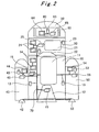
- Fig. 2 attached to the present application shows an outline of such a conventional aerospace vehicle system.
- Fig. 2 shows a two-step rocket having a first step rocket 10 and a second step rocket 20.
- the second step rocket 20 is set on the first step rocket 10.
- a fairing 30 is set on the second step rocket 20 as a front end portion.
- a fuel tank 11 and a rocket engine 12 are provided in the first step rocket 10.
- a plurality of boosters 40 and 50 are included, wherein each booster has a rocket engine 42 (52).
- a fuel tank 21 and a rocket engine 22 are provided in the second step rocket 20, a fuel tank 21 and a rocket engine 22 are provided.
- a satellite 60 is detachably installed in the fairing 30 set on the second step rocket 20, a satellite 60 is detachably installed.
- the second step rocket 20 is separated from the first step rocket 10 and then the separated second step rocket 20 is ignited.
- the satellite 60 is separated from the second step rocket 20 and the satellite 60 can be put on orbit.
- the first step rocket 10 and the second step rocket 20 have various kinds of sensors, radio devices and electronic devices (such as computers) are provided with respect to each rocket 10 and 20, respectively.
- the various kinds of the sensors, the radio devices and the electronic devices are controlled.
- each rocket 10 (20) has various kinds of sensors 13 (23) such as an acceleration sensor and angular acceleration (gyro meter), respectively. Further, each rocket 10 (20) has a radio device 14 (24) for communication with a radio base on the earth and an electronic device (such as computer) 15 (25) is included. The electronic device 15 (25) is electrically connected to the sensor 13 (23), the radio device 14 (24) and the rocket engine 12 (22) through a rocket exclusive use bus (signal lines) 70.
- sensors 13 such as an acceleration sensor and angular acceleration (gyro meter)
- each rocket 10 (20) has a radio device 14 (24) for communication with a radio base on the earth and an electronic device (such as computer) 15 (25) is included.
- the electronic device 15 (25) is electrically connected to the sensor 13 (23), the radio device 14 (24) and the rocket engine 12 (22) through a rocket exclusive use bus (signal lines) 70.
- various kinds of sensors 43 (53), a radio device 44 (54) and an electronic device 45 (54) are provided to the respective booster 40 (50).
- the electronic device 45 (55) is electrically connected to the various kinds of sensors 43 (53), the radio device 44 (54) and a rocket engine 42 (52) through a rocket exclusive use bus (signal lines).
- the electronic devices 15, 25, 45 and 55 can control the rocket engines 12, 22, 42 and 53, respectively.
- the satellite 60 is put on outer space by the two stepped rocket, the satellite 60 is controlled by itself by utilizing various kinds of sensors, a radio device and an electronic device (such as a computer), and those are equipped in the satellite for an exclusive use.
- various kinds of exclusive use satellite sensors 63, an exclusive use radio device 64 for communicating with a radio base on the earth and an exclusive use electronic device (such as computer) 65 are installed.
- the electronic device 65 is electrically connected to the various kinds of sensors 63 and the radio device 64 through an exclusive use satellite bus (signal lines) 80.
- the satellite 60 when the satellite 60 is separated from the two stepped rocket, in accordance with signals obtained by the various kinds of sensors 63 and commands received from the radio device 64, the satellite can be controlled by itself.
- U.S. Patent Publication No.2005/0150998 discloses a communication structure for an aerospace vehicle in which a satellite is not shipped.
- an aerospace vehicle comprises a space tool such as an artificial satellite (herein after, it is referred as "satellite") detachably attached to the aerospace vehicle and a one, two or more than two stepped rocket, the aerospace vehicle system being characterized in that the satellite comprises an electronic device for controlling the satellite after the satellite detached from the rocket and controlling the rocket before the satellite detached from the rocket.
- a space tool such as an artificial satellite (herein after, it is referred as "satellite") detachably attached to the aerospace vehicle and a one, two or more than two stepped rocket
- the aerospace vehicle system being characterized in that the satellite comprises an electronic device for controlling the satellite after the satellite detached from the rocket and controlling the rocket before the satellite detached from the rocket.
- an aerospace vehicle system comprises a satellite including a radio device and various kinds of sensors, the aerospace vehicle system being characterized in that the electronic device is connected to the radio device and the various kinds of sensors through signal lines in the aerospace vehicle system according to the present invention.
- an aerospace vehicle system comprises a rocket having a rocket engine with respective to each step rocket, the aerospace vehicle system being characterized in that the electronic device is connected to the rocket engine in each step rocket through signal lines in the aerospace vehicle system according to the present invention.
- an aerospace vehicle system comprises at least one booster attached to a rocket, the aerospace vehicle system being characterized in that the electronic device is connected to the booster of the rocket engine through signal lines in the aerospace vehicle system according to the present invention.
- an aerospace vehicle comprises a satellite detachably attached to the first step rocket, the second step rocket and more step rocket wherein an electronic device installed at the satellite controls not only the satellite but also each step rocket. Therefore, it is unnecessary for each step rocket to provide exclusive use sensors, an exclusive use radio device and an exclusive use electronic device. As a result, the manufacturing cost and the total body weight of the rocket can be decreased, a communication/control system in each rocket can be simplified and a time period for launching the aerospace vehicle can be shortened.
- an electronic device installed in the satellite controls the satellite through signal lines in accordance with signals obtained from various kinds of sensors and commands received from the radio device
- an electronic device installed in the satellite controls a rocket engine of each step rocket.
- an electronic device installed in the satellite controls a rocket engine of each booster attached to a respective step rocket through signal lines.
- the present invention relates to an aerospace vehicle in which a satellite is installed, wherein the aerospace vehicle has a two stepped rocket or a more than two stepped rocket and an installed satellite is capable of separating from the rocket.
- Rocket exclusive use sensors, rocket exclusive use radio devices and rocket exclusive use electronic devices are not installed in the rocket.
- the rocket is controlled by an electronic device installed in the satellite.
- An embodiment as described below is the best mode of the embodiment of the present invention.
- Fig. 1 shows an aerospace vehicle system of the first embodiment according to the present invention.
- the embodiment employs a two stepped rocket consisting of the first step rocket 10 and the second step rocket 20.
- the second step rocket 20 is provided on the first step rocket 10 and a fairing 30 is set on the second step rocket 20 as a front end portion.
- the first step rocket 10 comprises a fuel tank 11 and a rocket engine 12. Further, a plurality of boosters 40 and 50 having rocket engines 42 and 52 are attached.
- the second step rocket 20 comprises a fuel tank 21 and a rocket engine 22.
- a satellite 60 is detachably installed.
- the aerospace vehicle system may employ a one stepped rocket and exclude the boosters 40 and 50.
- the first step rocket 10 and the second step rocket 20 do not need to comprise various kinds of sensors such as an acceleration sensor, an angular acceleration sensor (gyro meter), a radio device for communicating with a radio base on the earth and an electronic device (such as computer), respectively.
- sensors such as an acceleration sensor, an angular acceleration sensor (gyro meter), a radio device for communicating with a radio base on the earth and an electronic device (such as computer), respectively.
- the various kinds of sensors, the radio device and the electronic device are not installed in the boosters 40 and 50.
- various kinds of sensors such as an acceleration sensor 63, a radio device for communicating with a radio base on the earth and an electronic device (such as computer) 65 are only installed in the satellite 60 in the fairing.
- the satellite 60 can be detached from the fairing on the second step rocket 20.
- the electronic device 65 is electrically connected to the various kinds of sensors 63 and the radio device 64 through a rocket-satellite common bus (signal line) 90. Further, the rocket engine 12 of the first step rocket 10 and the rocket engine 22 of the second step rocket 20 and jet engines 42 and 52 of the boosters 40 and 50 are electrically connected within the aerospace vehicle system. As the rocket-satellite common use bus 90, a bus disclosed in the patent document 1 is applicable.
- the electronic device 65 can control all the rocket engines 12, 22, 42 and 52 in accordance with signals obtained from various kinds of sensors 63 and commands received from the radio device 64.
- the satellite is controlled by itself in accordance with signals from various kinds of sensors 63 and commands received from the radio device 64.
- a pressure sensor and a thermo sensor are adapted to the rocket engines 12, 22, 42 and 52. These sensors and the electronic device 65 are electrically connected through the rocket-satellite common use bus 90.
- the rocket-satellite common use bus 90 is divided into a satellite portion and a rocket portion.
- rocket exclusive-use sensors, an exclusive use radio device and an exclusive use electromagnetic device are not installed in the first step rocket 10 and the second step rocket 20, respectively.
- the electronic device 65 installed in the satellite 60 controls the first step rocket 10 and the second step rocket 20.
- the manufacturing cost and the total weight of the first step rocket 10 and the second step rocket can be reduced by omitting these equipments.
- an effect is obtained that an aerospace vehicle system arranged within the first step rocket 10 and the second step rocket 20 can be simplified and a time period for preparing a launch of an aerospace vehicle can be shortened.
- the present invention provides the minimum system with the minimum number of electronic devices, sensors and radio devices so that an aerospace vehicle can be manufactured with remarkably low manufacturing cost and a lighter total weight. A launch of the aerospace vehicle can be very adequately prepared.
- the satellite 60 is self-controlled by the electronic device 65 installed in the satellite 60.
- the electronic device 65 installed in the satellite 60 has sufficient capability for controlling the first step rocket 10 and the second step rocket 20 as well as the satellite 60.
- rocket engines 12 and 22 use liquid fuel in the fuel tanks 11 and 12
- solid fuel is also applicable to the present invention instead of the liquid fuel.
- the present invention is broadly applicable in an industry as an aerospace vehicle system with a simple structure, a low manufacturing cost and light weight.
Landscapes
- Engineering & Computer Science (AREA)
- Remote Sensing (AREA)
- Aviation & Aerospace Engineering (AREA)
- Power Engineering (AREA)
- Chemical & Material Sciences (AREA)
- Combustion & Propulsion (AREA)
- Radar, Positioning & Navigation (AREA)
- Arrangements For Transmission Of Measured Signals (AREA)
- Radio Relay Systems (AREA)
Claims (4)
- Raumfahrzeugsystem mit:einem Raumfahrzeug (30) mit einer eine, zwei oder nehr Stufen umfassenden Rakete (10, 20); undeinem Satelliten (60), der abnehmbar mit dem Fahrzeug verbunden ist; wobeider Satellit (60) eine elektronische Vorrichtung (65) zur Steuerung des Satelliten (60) umfasst, wenn der Satellit (60) von der Rakete (10, 20) getrennt ist;dadurch gekennzeichnet, dassdie elektronische Vorrichtung (65) ausgestaltet ist für die Steuerung der Rakete (10, 20), bevor der Satellit (60) von der Rakete (10, 20) getrennt wird.
- Raumfahrzeugsystem nach Anspruch 1, dadurch gekennzeichnet, dass der Satellit (60) eine Funkvorrichtung (64) und verschiedene Arten von Sensoren (63) umfasst, und wobei die elektronische Vorrichtung (65) mit der Funkvorrichtung und den verschiedenen Arten von Sensoren (63) über Signalleitungen (90) verbunden ist.
- Raumfahrzeugsystem nach Anspruch 1 oder Anspruch 2, dadurch gekennzeichnet, dass die Rakete (10, 20) eine Raketenmaschine (40, 50) für jede Stufe der Rakete (10, 20) hat, und wobei die elektronische Vorrichtung (65) mit der Raketenmaschine (12, 22) jeder Stufe der Rakete über Signalleitungen (90) verbunden ist.
- Raumfahrzeugsystem nach Anspruch 1, Anspruch 2 oder Anspruch 3, dadurch gekennzeichnet, dass ein Booster (40, 50) mit der Rakete (10, 20) verbunden ist, und dass die elektrische Vorrichtung (65) mit dem Booster (40, 50) über Signalleitungen (90) verbunden ist.
Applications Claiming Priority (1)
| Application Number | Priority Date | Filing Date | Title |
|---|---|---|---|
| JP2008034025A JP5030811B2 (ja) | 2008-02-15 | 2008-02-15 | 宇宙機システム |
Publications (2)
| Publication Number | Publication Date |
|---|---|
| EP2098451A1 EP2098451A1 (de) | 2009-09-09 |
| EP2098451B1 true EP2098451B1 (de) | 2013-02-20 |
Family
ID=40668154
Family Applications (1)
| Application Number | Title | Priority Date | Filing Date |
|---|---|---|---|
| EP08164455A Active EP2098451B1 (de) | 2008-02-15 | 2008-09-16 | Luftfahrzeugsystem |
Country Status (3)
| Country | Link |
|---|---|
| US (1) | US10501210B2 (de) |
| EP (1) | EP2098451B1 (de) |
| JP (1) | JP5030811B2 (de) |
Families Citing this family (4)
| Publication number | Priority date | Publication date | Assignee | Title |
|---|---|---|---|---|
| DE102011050848B4 (de) | 2011-06-06 | 2015-10-01 | ITM Isotopen Technologien München AG | Schichtaufbau zur epidermalen Radionuklidtherapie |
| CN104260901B (zh) * | 2014-09-11 | 2016-08-24 | 上海卫星工程研究所 | 模块化的双组元推进系统 |
| CN105183927B (zh) * | 2015-05-11 | 2018-04-06 | 上海宇航系统工程研究所 | 一种多星分离参数优化方法 |
| CN112960146A (zh) * | 2021-01-19 | 2021-06-15 | 中国人民解放军63921部队 | 一种助推器和芯级整体式分离的液体运载火箭 |
Family Cites Families (20)
| Publication number | Priority date | Publication date | Assignee | Title |
|---|---|---|---|---|
| US3116035A (en) * | 1959-10-01 | 1963-12-31 | Bell Telephone Labor Inc | Attitude control of earth satellites |
| US3768254A (en) * | 1962-07-09 | 1973-10-30 | Boeing Co | Rocket propulsion method and means |
| US4471926A (en) * | 1979-10-29 | 1984-09-18 | Trw Inc. | Transfer vehicle for use in conjunction with a reusable space shuttle |
| US4451017A (en) * | 1982-09-30 | 1984-05-29 | The United States Of America As Represented By The Administrator, National Aeronautics And Space Administration | Three stage rocket vehicle with parallel staging |
| US5186419A (en) * | 1990-01-30 | 1993-02-16 | Scott David R | Space transfer vehicle and integrated guidance launch system |
| US5152482A (en) * | 1990-06-29 | 1992-10-06 | Standard Space Platforms Corp. | Modular mother satellite bus for subsidiary payloads |
| US5271582A (en) * | 1990-06-29 | 1993-12-21 | Standard Space Platforms Corp. | Modular mother satellite bus for subsidiary payloads |
| JP3035324B2 (ja) * | 1990-09-03 | 2000-04-24 | 日本電信電話株式会社 | 衛星スピン軸変更方法 |
| US5667171A (en) * | 1995-04-28 | 1997-09-16 | Hughes Aircraft Company | Satellite spin axis stabilization using a single degree of freedom transverse momentum storage device |
| JP3641660B2 (ja) * | 1995-08-23 | 2005-04-27 | 独立行政法人 宇宙航空研究開発機構 | 飛行体の垂直着陸制御指令装置 |
| US6921051B2 (en) * | 2001-03-27 | 2005-07-26 | Jacob B. Lopata | System for the delivery and orbital maintenance of micro satellites and small space-based instruments |
| JP2002310004A (ja) | 2001-04-16 | 2002-10-23 | Mitsubishi Heavy Ind Ltd | ロケットノズル |
| JP4632112B2 (ja) * | 2001-07-09 | 2011-02-16 | 独立行政法人 宇宙航空研究開発機構 | 衛星の打ち上げ方法 |
| JP2004210032A (ja) * | 2002-12-27 | 2004-07-29 | Mitsubishi Electric Corp | 編隊飛行衛星 |
| US6968673B1 (en) * | 2003-11-14 | 2005-11-29 | Knight Andrew F | Cool gas generator and ultra-safe rocket engine |
| US7261028B2 (en) | 2003-12-22 | 2007-08-28 | Alliant Techsystems, Inc. | Ordnance system with common bus, method of operation and aerospace vehicle including same |
| US7137588B2 (en) * | 2004-01-06 | 2006-11-21 | United Technologies Corporation | Ballistic target defense system and methods |
| JP2007085627A (ja) * | 2005-09-21 | 2007-04-05 | Mitsubishi Electric Corp | 誘導ミサイル |
| US8104719B2 (en) * | 2005-11-17 | 2012-01-31 | Raytheon Company | Digital interface unit (DIU) and method for controlling stages of a multi-stage missle |
| EP2122296B1 (de) * | 2007-01-18 | 2016-08-03 | Raytheon Company | Anpassbare elektronikarchitektur |
-
2008
- 2008-02-15 JP JP2008034025A patent/JP5030811B2/ja active Active
- 2008-09-16 EP EP08164455A patent/EP2098451B1/de active Active
- 2008-10-20 US US12/254,456 patent/US10501210B2/en active Active
Also Published As
| Publication number | Publication date |
|---|---|
| EP2098451A1 (de) | 2009-09-09 |
| US10501210B2 (en) | 2019-12-10 |
| JP2009190593A (ja) | 2009-08-27 |
| US20090206205A1 (en) | 2009-08-20 |
| JP5030811B2 (ja) | 2012-09-19 |
Similar Documents
| Publication | Publication Date | Title |
|---|---|---|
| US6941850B1 (en) | Self-contained airborne smart weapon umbilical control cable | |
| US9796484B2 (en) | Satellite system comprising two satellites attached to each other and method for launching them into orbit | |
| US8136765B2 (en) | Method of launching into operational orbit an artificial satellite and associated propulsion device | |
| US8367992B1 (en) | Aircraft, missile, projectile, or underwater vehicle with reconfigurable control surfaces | |
| EP3293122B1 (de) | Initiationssystem für eine raumfahrzeugvorrichtung | |
| AU2017378131B2 (en) | System and method for stores communications | |
| US20170233109A1 (en) | Reusable Staging System For Launch Vehicles | |
| EP2098451A1 (de) | Luftfahrzeugsystem | |
| US5163640A (en) | Active spin axis control for spinning space vehicles | |
| US11047340B2 (en) | Integrated warhead ESAD/multi-pulse rocket motor EISD device | |
| US7893390B2 (en) | Guided missile | |
| AU2007343894B2 (en) | Scalable electronics architecture | |
| US9403605B2 (en) | Multiple stage tractor propulsion vehicle | |
| US10895443B2 (en) | More compact side force steering and attitude control system, and a vehicle including such a system | |
| EP3208199B1 (de) | Vorrichtung zur steuerung der änderung einer umlaufbahn eines weltraumobjekts im weltraum oder zur beseitigung eines weltraumobjekts aus dem weltraum und system und verfahren zur änderung einer umlaufbahn eines weltraumobjekts im weltraum oder zur beseitigung eines weltraumobjekts aus dem weltraum | |
| RU2428358C1 (ru) | Космическая головная часть для группового запуска спутников | |
| EP4227633A1 (de) | Vorrichtung zur bereitstellung einer schnittstelle zwischen einem flugkörper und einer startplattform | |
| Novotney et al. | Qualification of a networked pyrotechnic initiation system for the CST-100 starliner spacecraft | |
| WO2023152484A1 (en) | Apparatus for providing an interface between a missile and a launch platform | |
| CA3083131A1 (en) | Multipoint separation system | |
| Pegg et al. | Airbreathing Hypersonic Vision-Operational-Vehicles Design Matrix | |
| Rohrbaugh et al. | THE INERTIAL UPPER STAGE—A SPACE TRANSPORTATION SYSTEM ELEMENT NEARING FIRST FLIGHT |
Legal Events
| Date | Code | Title | Description |
|---|---|---|---|
| PUAI | Public reference made under article 153(3) epc to a published international application that has entered the european phase |
Free format text: ORIGINAL CODE: 0009012 |
|
| 17P | Request for examination filed |
Effective date: 20080916 |
|
| AK | Designated contracting states |
Kind code of ref document: A1 Designated state(s): AT BE BG CH CY CZ DE DK EE ES FI FR GB GR HR HU IE IS IT LI LT LU LV MC MT NL NO PL PT RO SE SI SK TR |
|
| AX | Request for extension of the european patent |
Extension state: AL BA MK RS |
|
| AKX | Designation fees paid |
Designated state(s): DE FR GB |
|
| 17Q | First examination report despatched |
Effective date: 20101111 |
|
| RIC1 | Information provided on ipc code assigned before grant |
Ipc: B64G 1/28 20060101ALI20120809BHEP Ipc: B64G 1/42 20060101ALI20120809BHEP Ipc: B64G 1/64 20060101ALI20120809BHEP Ipc: B64G 1/24 20060101ALI20120809BHEP Ipc: B64G 1/00 20060101AFI20120809BHEP Ipc: B64G 1/40 20060101ALI20120809BHEP |
|
| GRAP | Despatch of communication of intention to grant a patent |
Free format text: ORIGINAL CODE: EPIDOSNIGR1 |
|
| GRAS | Grant fee paid |
Free format text: ORIGINAL CODE: EPIDOSNIGR3 |
|
| GRAA | (expected) grant |
Free format text: ORIGINAL CODE: 0009210 |
|
| AK | Designated contracting states |
Kind code of ref document: B1 Designated state(s): DE FR GB |
|
| REG | Reference to a national code |
Ref country code: GB Ref legal event code: FG4D |
|
| REG | Reference to a national code |
Ref country code: DE Ref legal event code: R096 Ref document number: 602008022262 Country of ref document: DE Effective date: 20130418 |
|
| PLBE | No opposition filed within time limit |
Free format text: ORIGINAL CODE: 0009261 |
|
| STAA | Information on the status of an ep patent application or granted ep patent |
Free format text: STATUS: NO OPPOSITION FILED WITHIN TIME LIMIT |
|
| 26N | No opposition filed |
Effective date: 20131121 |
|
| REG | Reference to a national code |
Ref country code: DE Ref legal event code: R097 Ref document number: 602008022262 Country of ref document: DE Effective date: 20131121 |
|
| REG | Reference to a national code |
Ref country code: FR Ref legal event code: PLFP Year of fee payment: 9 |
|
| REG | Reference to a national code |
Ref country code: FR Ref legal event code: PLFP Year of fee payment: 10 |
|
| REG | Reference to a national code |
Ref country code: FR Ref legal event code: PLFP Year of fee payment: 11 |
|
| PGFP | Annual fee paid to national office [announced via postgrant information from national office to epo] |
Ref country code: DE Payment date: 20250730 Year of fee payment: 18 |
|
| PGFP | Annual fee paid to national office [announced via postgrant information from national office to epo] |
Ref country code: GB Payment date: 20250731 Year of fee payment: 18 |
|
| PGFP | Annual fee paid to national office [announced via postgrant information from national office to epo] |
Ref country code: FR Payment date: 20250808 Year of fee payment: 18 |