EP2098442A2 - Straddle type vehicle - Google Patents
Straddle type vehicle Download PDFInfo
- Publication number
- EP2098442A2 EP2098442A2 EP09250257A EP09250257A EP2098442A2 EP 2098442 A2 EP2098442 A2 EP 2098442A2 EP 09250257 A EP09250257 A EP 09250257A EP 09250257 A EP09250257 A EP 09250257A EP 2098442 A2 EP2098442 A2 EP 2098442A2
- Authority
- EP
- European Patent Office
- Prior art keywords
- fender
- width direction
- fork
- straddle type
- type vehicle
- Prior art date
- Legal status (The legal status is an assumption and is not a legal conclusion. Google has not performed a legal analysis and makes no representation as to the accuracy of the status listed.)
- Granted
Links
Images




Classifications
-
- B—PERFORMING OPERATIONS; TRANSPORTING
- B62—LAND VEHICLES FOR TRAVELLING OTHERWISE THAN ON RAILS
- B62J—CYCLE SADDLES OR SEATS; AUXILIARY DEVICES OR ACCESSORIES SPECIALLY ADAPTED TO CYCLES AND NOT OTHERWISE PROVIDED FOR, e.g. ARTICLE CARRIERS OR CYCLE PROTECTORS
- B62J15/00—Mud-guards for wheels
Definitions
- the present invention relates to a straddle type vehicle including a pair of front forks rotatably supporting an axle of a front wheel and a front fender disposed radially outwardly of the front wheel.
- straddle type vehicles such as motorcycles are provided with a front fender for preventing pebbles, rainwater, and so forth flung up by a front wheel from scattering.
- a front fender is known that is disposed between a pair of front forks rotatably supporting an axle of a front wheel and that has a function for protecting the front forks.
- Such an arrangement is disclosed in, for example, JP-A-2005-88659 .
- a fork cover which swells upward is provided on the front fender in front of the front forks.
- a front fender having the function for protecting the front forks allows prevention of damage to the front forks, in particular inner tubes of the front forks.
- the conventional front fender described above has the following problem. Specifically, there are cases that the front forks, particularly the inner tubes thereof, are yet damaged by pebbles and the like flung up by the front wheel with the above front fender having the function for protecting the front forks. In other words, there is room for improvement in prevention of damage to the front forks by pebbles and the like in the conventional front fender.
- the present invention is made in consideration of such a problem, and the object is to provide a straddle type vehicle that is provided with a front fender having a function for protecting front forks and that allows more secure prevention of damage to the front forks.
- a straddle type vehicle comprising:
- a straddle type vehicle including: a front wheel; a pair of front forks rotatably supporting an axle of the front wheel; and a front fender disposed radially outwardly of the front wheel and between the pair of front forks, in which the front fender has a fork protecting part provided in front of the front forks, the fork protecting part swells outward in the vehicle width direction, the fork protecting part has a front wall positioned in a front part of the straddle type vehicle, and an inclination of the front wall with respect to a road surface on which the straddle type vehicle is disposed is larger than an inclination of an outer peripheral surface of a central part of the front fender in the vehicle width direction in the front fender in which the front wall is provided.
- the front wall formed on the front fender in front of the front fork can protect the front fork from pebbles and the like flung up by the front wheel and more securely prevent damage to the front fork.
- the fork protecting part may have a protrusion protruding above the outer peripheral surface of the front fender.
- a line may perpendicularly intersect the front wall and extend obliquely forwardly of the straddle type vehicle in a plan view of the straddle type vehicle.
- a protector outer end of the fork protecting part in the vehicle width direction may be positioned inwardly in the vehicle width direction of a fork outer end of the front fork in the vehicle width direction.
- the protector outer end may be positioned outwardly in the vehicle width direction of a center of the front fork in the vehicle width direction.
- the front fork may be cylindrically shaped.
- the fork protecting part may have a rear wall facing the front fork.
- the rear wall may be formed in the rear of the front wall and may be curved along an outer periphery of the front fork.
- An inclined wall may be formed in an inner part of the protrusion in the vehicle width direction.
- the inclined wall may be inclined outwardly in the vehicle width direction.
- An upper part (of the inclined wall may be positioned outwardly of a lower part of the inclined wall in the vehicle width direction.
- the upper part of the inclined wall may be inclined outwardly in the vehicle width direction to a greater degree than the lower part of the inclined wall.
- the front fender may have a fender front section disposed in front of the front forks, and a fender rear section (extending continuously from the fender front section to the rear of the front forks.
- the fender front section and the fender rear section may be integrally formed. Alternatively, the sections may be separately formed.
- the fender rear section may have an inner wall extending in the fore-and-aft direction of the straddle type vehicle.
- the inner wall may be disposed inwardly of the front fork in the vehicle width direction.
- the inner wall may overlap with the fork protecting part in a side view of the straddle type vehicle.
- a mount part on which the inner wall of the front fender is mounted may be formed on an inner part of the front fork in the vehicle width direction.
- the mount part may be formed on each of a left front fork and a right front fork (constructing the front forks.
- the inner wall may be' formed to face each of the right and left front forks.
- the front fender may be mounted on the mount parts using a connecting member for connecting the pair of inner walls together.
- the connecting member may be formed along a shape of an inner surface of the front fender.
- the connecting member may be U-shaped in a cross section taken along the longitudinal direction of the front fork and the vehicle width direction.
- the present invention may provide a straddle type vehicle that is provided with a front fender having a function for protecting front forks and that allows more secure prevention of damage to the front forks.
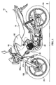
- FIG. 1 is a left side view of the motorcycle 10 disposed on a road surface R.
- the motorcycle 10 has a vehicle body frame 30 forming a framework of the motorcycle 10.
- the motorcycle 10 has a front wheel 20, a fuel tank 50, an engine 40, a seat 70, a rear wheel 90, and a front fender 100.
- the fuel tank 50, the engine 40, and the seat 70 are mounted on the vehicle body frame 30.
- the front wheel 20 is rotatably supported by a pair of front forks 21L and 21R connected to the vehicle body frame 30.
- FIG. 1 shows the left front fork 21L.
- the pair of front forks 21L and 21R are connected to a steering shaft (not shown) via a bridge (not shown).
- the steering shaft (not shown) is supported by a steering head pipe 30hp of the vehicle body frame 30 so as to be rotatable to left and right with respect to the traveling direction of the motorcycle 10.
- the front fender 100 is mounted on the pair of front forks 21L and 21R.
- the front fender 100 is disposed radially outwardly of the front wheel 20 and between the pair of front forks 21L and 21R.
- the engine 40 is a power unit for generating driving force of the motorcycle 10.
- the engine 40 is mounted on the vehicle body frame 30 in the general center of the motorcycle 10 in the fore-and-aft direction.
- the engine 40 generates driving force to be transmitted to the rear wheel 90.
- Driving force generated in the engine 40 is transmitted to the rear wheel 90 through a chain.
- the seat 70 is disposed in the rear of the fuel tank 50. A rider is to be seated on the seat 70.
- the fuel tank 50 stores fuel to be supplied to the engine 40.
- the fuel tank 50 is disposed above the engine 40.
- the fuel tank 50 is disposed in front of the seat 70.
- shrouds Vehicle body covers (hereinafter referred to as "shrouds") 60 are disposed on both sides of the fuel tank 50.
- the shroud 60 extends downwardly of the fuel tank 50.
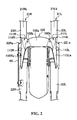
- FIG. 2 is a front view showing the front fender 100 mounted on the front forks 21L and 21R.
- FIG. 3 is a left side view showing the front fender 100 mounted on the front forks 21L and 21R.
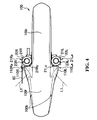
- FIG. 4 is a plan view showing the front fender 100 mounted on the front forks 21L and 21R.
- the front fork 21L positioned on the left side has a cylindrical outer tube 22L and a cylindrical inner tube 23L.
- the front fork 21R positioned on the right side similarly has an outer tube 22R and an inner tube 23R.
- the front forks 21L and 21R are upright forks that the outer tubes 22L and 22R are disposed below the inner tubes 23L and 23R.
- the outer tube 22L has an upper end 22La in which the inner tube 23L is inserted.
- the outer tube 22R has an upper end 22Ra in which the inner tube 23R is inserted.
- a license plate 80 may be disposed on the outer tube 23R.
- a construction of the front fender 100 will now be described with reference to FIGs. 2 through 4 .
- the front fender 100 has fork protectors 110L and 110R.
- the fork protectors 110L and 110R construct fork protecting parts.
- the fork protectors 110L and 110R swell or bulge outwardly of the front fender 100 in the vehicle width direction.
- the fork protector 110L has an outer end 110La protruding the most outwardly in the vehicle width direction.
- the fork protector 110R has an outer end 110Ra protruding the most outwardly in the vehicle width direction.
- the outer ends 110La and 110Ra protrude outwardly of shoulder surfaces 100b of the front fender 100 in the vehicle width direction.
- the outer ends 110La and 110Ra are positioned inwardly in the vehicle width direction of outer ends 21La and 21Ra of the front forks 21L and 21R in the vehicle width direction (see FIG. 4 ).
- the outer ends 110La and 110Ra are positioned outwardly in the vehicle width direction of center lines 21Lb and 21Rb of the front forks 21L and 21R in the vehicle width direction.
- outer ends 110La and 110Ra construct protector outer ends and the outer ends 21La and 21Ra construct fork outer ends.
- the fork protectors 110L and 110R are formed in front of the front forks 21L and 21R with the front fender 100 mounted on the front forks 21L and 21R (see FIGs. 3 and 4 ).
- the fork protector 110L has a front wall 111L positioned in a front part of the motorcycle 10 to face generally forward.
- the fork protector 110R has a front wall 111R positioned in a front part of the motorcycle 10 to face generally forward.
- an inclination A1 of the front walls 111L and 111R with respect to the road surface R on which the motorcycle 10 is disposed is larger than an inclination A2 of an outer peripheral surface of a central part of the front fender 100 in the vehicle width direction in positions in which the front walls 111L and 111R are disposed.
- the road surface R may be assumed to be generally planar between the points at which the front and rear wheels 20, 90 contact said road surface R.
- the front fender 100 has a fender front section 100f and a fender rear section 100r.
- the fender front section 100f is disposed in front of the front forks 21L and 21R.
- the fender rear section 100r extends continuously from the fender front section 100f to the rear of the front forks 21L and 21R.
- the fender front section 100f and the fender rear section 100r are integrally formed.
- a line L1 perpendicularly intersecting the front walls 111L and 111R extends obliquely forwardly of the motorcycle 10 in a plan view of the motorcycle 10.
- the fork protectors 110L and 110R have protrusions 114L and 114R.
- the protrusion 114L protrudes above the upper end 22La of the outer tube 22L in the vertical direction of the motorcycle 10.
- the protrusion 114R protrudes above the upper end 22Ra of the outer tube 22R in the vertical direction of the motorcycle 10.
- the protrusions 114L and 114R protrude above an outer peripheral surface 100a of the central part of the front fender 100 in the vehicle width direction.
- FIG. 5 is a perspective view of the front fender 100.
- FIG. 6 is a front view of the front fender 100.
- FIG. 7 is a left side view of the front fender 100.
- FIG. 8 is a plan view of the front fender 100.
- Inclined walls 112L and 112R inclined outwardly in the vehicle width direction are formed in inner parts of the protrusions 114L and 114R in the vehicle width direction.
- the inclined wall 112L has an upper part 112La and a lower part 112Lb.
- the upper part 112La is positioned outwardly of the lower part 112Lb in the vehicle width direction.
- the upper part 112La is inclined outwardly in the vehicle width direction to a greater degree than the lower part 112Lb.
- the inclined wall 112R has an upper part 112Ra and a lower part 112Rb.
- the upper part 112Ra is positioned outwardly of the lower part 112Rb in the vehicle width direction.
- the upper part 112Ra is inclined outwardly in the vehicle width direction to a greater degree than the lower part 112Rb.
- the fork protector 110L has a rear wall 113L facing the front wall 111L.
- the rear wall 113L is formed in the rear of the front wall 111L and curves along an outer periphery 21Lc (not shown in FIG. 7 , see FIG. 4 ) of the front fork 21L.
- the fork protector 110R has a rear wall 113R facing the front wall 111R.
- the rear wall 113R is formed in the rear of the front wall 111R and curves along an outer periphery 21Rc (not shown in FIG. 7 , see FIG. 4 ) of the front fork 21R.
- the fender rear section 100r has an inner wall 120L extending in the fore-and-aft direction of the motorcycle 10.
- the inner wall 120L is formed to face the front fork 21L. Holes 121L and 122L used for mounting on the front fork 21L are provided in the inner wall 120L.
- the fender rear section 100r has an inner wall 120R extending in the fore-and-aft direction of the motorcycle 10.
- the inner wall 120R is formed to face the front fork 21R.
- FIG. 9 is a plan view showing the inside of the front fender 100.
- the front fender 100 has support walls 115L and 115R inside.
- the inner wall 120L extends continuously from the rear wall 113L, forwardly of the motorcycle 10, and continuously to the support wall 115L inside the front fender 100.
- the inner wall 120R extends continuously from the rear wall 113R, forwardly of the motorcycle 10, and continuously to the support wall 115R inside the front fender 100.
- the support walls 115L and 115R extend in directions that the protrusions 114L and 114R protrude above the outer peripheral surface 100a of the front fender 100.
- the front fender 100 is formed by injection molding that a resin material is injected into a metal mold by pressure when it is produced.
- the metal mold is separated in the vertical direction of the front fender 100.
- the support walls 115L and 115R are formed along the separating direction of the mold.
- the support walls 115L and 115R have a function for supporting the protrusions 114L and 114R during separation from the mold.
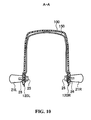
- FIG. 10 is a cross-sectional view taken along line A-A of FIG. 3 .
- FIG. 11 is a cross-sectional view showing the vicinity of parts on which the front fender 100 is mounted taken along line B-B of FIG. 3 .
- a mount 21d on which an inner wall 120L of the front fender 100 is mounted is formed on an inner part of the front fork 21L in the vehicle width direction. Specifically, the mount 21d is formed on an inner part of the outer tube 23L in the vehicle width direction. The mount 21d is disposed to face the inner wall 120L.
- the mount 21d is similarly formed on an inner part of the front fork 21R (specifically the outer tube 23R) in the vehicle width direction (the mount of the outer tube 23R is not shown in FIG. 11 ).
- the mount 21d constructs a mount part.
- the front fender 100 is mounted on the mounts 21d using a fender stay 150 connecting the pair of inner walls 120 together.
- the fender stay 150 is formed along a shape of an inner surface of the front fender 100.
- the fender stay 150 is U-shaped in a cross section taken along the longitudinal direction of the front forks 21L and 21R and the vehicle width direction. In this embodiment, the fender stay 150 constructs a connecting member.
- the front fender 100 is mounted by bolts 25, which are inserted from an inner side to an outer side in the vehicle width direction of the motorcycle 10.
- Collars 26 for absorbing a size difference between an outer diameter of the bolt 25 and a hole diameter of the holes 121L and 122L are disposed in the holes 121L and 122L.
- the bolts 25 are inserted in the holes 121L and 122L in which the collars 26 are disposed and screwed into female threads provided in the mount 21d of the front fork 21.
- the inclination A1 of the front walls 111L and 111R of the fork protectors 110L and 110R with respect to the road surface R is larger than the inclination A2 of the outer peripheral surface of the central part of the front fender 100 in the vehicle width direction in the positions in which the front walls 111L and 111R of the front fender 100 are provided.
- the front walls 111L and 111R formed in front of the front forks 21L and 21R in the front fender 100 can protect the front forks 21L and 21R from pebbles and the like flung up by the front wheel. Further, it is possible to more securely prevent damage to the front forks 21L and 21R, in particular the inner tubes 22L and 22R.
- the front forks 21 are so-called upright forks.
- the protrusions 114L and 114R are positioned higher than the upper ends 22La and 22Ra in the vertical direction of the motorcycle 10.
- the inner tubes 22L and 22R on the sides of the outer tubes 23L and 23R frequently go into and out of the outer tubes 23L and 23R due to stroke movements of the front forks 21L and 21R. Therefore, oil seals on the sides of the outer tubes 23L and 23R are apt to be damaged when the inner tubes 22L and 22R on the side of the outer tubes 23L and 23R are damaged.
- the inner tubes 22L and 22R on the sides of the outer tubes 23L and 23R are protected from pebbles and the like in the motorcycle 10. Therefore, the front forks 21L and 21R can be securely prevented from damage. Accordingly, it is possible to prevent oil leakage due to damage to the inner tubes 22L and 22R on the sides of the outer tubes 23L and 23R.
- the line L1 perpendicularly intersecting the front walls 111L and 111R extends obliquely forwardly of the motorcycle 10 in a plan view of the motorcycle 10.
- the motorcycle 10 can protect the front forks 21L and 21R and more securely prevent damage to the front forks 21L and 21R.
- the outer ends 110La and 110Ra are positioned inwardly in the vehicle width direction of the outer ends 21La and 21Ra of the front forks 21L and 21R in the vehicle width direction.
- the outer ends 110La and 110Ra are positioned inwardly in the vehicle width direction of the center lines 21b of the front forks 21L and 21R in the vehicle width direction.
- the motorcycle 10 can securely protect the front forks 21L and 21R with a narrower vehicle width.
- the front forks 21L and 21R are cylindrically shaped.
- the rear walls 113L and 113R in the fork protectors 110L and 110R facing the front forks 21L and 21R curve along the outer peripheries 21Lc and 21Rc of the front forks 21L and 21R.
- the front fender 100 can securely protect the front forks 21L and 21R, in particular the inner tubes 22L and 22R on the sides of the outer tubes 23L and 23R.
- the inclined walls 112L and 112R inclined outwardly in the vehicle width direction are formed in the inner parts of the protrusions 114L and 114R in the vehicle width direction.
- the upper parts 112La and 112Ra are positioned outwardly of the lower parts 112Lb and 112Rb in the vehicle width direction.
- the upper parts 112La and 112Ra are inclined outwardly in the vehicle width direction to a greater degree than the lower parts 112Lb and 112Rb.
- the thus configured motorcycle 10 can repel pebbles and the like flying to the motorcycle 10 outwardly.
- the motorcycle 10 can protect the front forks 21L and 21R and more securely prevent damage to the front forks 21L and 21R.
- the front fender 100 has the fender front section 100f and the fender rear section 100r.
- the fender front section 100f and the fender rear section 100r are integrally formed.
- the support walls 115L and 115R are formed on the inner surface of the front fender 100.
- the support walls 115L and 115R extend in the directions that the protrusions 114L and 114R protrude.
- the support walls 115L and 115R can support the protrusions 114L and 114R during separation from the mold. In other words, the support walls 115L and 115R can retain the shapes of the protrusions 114L and 114R during separation from the mold.
- the protrusions protruding upwardly of the outer peripheral surface 100a of the front fender 100 can be formed in a production method using a metal mold. Thereby, production efficiency of the front fender 100 can be improved.
- the inner walls 120 are disposed to face the inner parts of the front forks 21L and 21R in the vehicle width direction.
- the mounts 21d on which the inner walls 120 are mounted are formed on the inner parts of the front forks 21L and 21R in the vehicle width direction.
- the front fender 100 is mounted on the mounts 21d using the fender stay 150 connecting the inner walls 120 together.
- the front fender 100 can be firmly mounted on the front forks 21L and 21R.
- the fender stay 150 is formed along the shape of the inner surface of the front fender 100.
- the fender stay 150 is U-shaped in a cross section taken along the longitudinal direction of the front forks 21L and 21R and the vehicle width direction.
- the fender stay 150 can be prevented from interfering with the front wheel 20.
- the front fender 100 can be firmly mounted on the front forks 21L and 21R, and the external appearance of the motorcycle 10 can be improved.
- the fork protectors 110L and 110R have the protrusions 114L and 114R protruding above the outer peripheral surface 100a of the front fender 100.
- the outer peripheral surface 100a positioned between the protrusions 114L and 114R may protrude to a level generally equivalent to the protrusions 114L and 114R.
- the line perpendicularly intersecting the front walls 111L and 111R in a plan view of the motorcycle 10 extend obliquely forwardly of the motorcycle 10.
- the line is not limited to the angle of the line L1 shown in FIG. 4 .
- the line may extend obliquely forwardly and inwardly in the vehicle width direction of the motorcycle 10.
- the outer ends 110La and 110Ra protrude outwardly of the shoulder surfaces 100b of the front fender 100 in the vehicle width direction and are positioned outwardly in the vehicle width direction of the center lines 21Lb and 21Rb of the front forks 21L and 21R in the vehicle width direction.
- the outer ends 110La and 110Ra be positioned inwardly in the vehicle width direction of the outer ends 21La and 21Ra of the front forks 21L and 21R in the vehicle width direction.
- the outer ends 110La and 110Ra may be positioned inwardly in the vehicle width direction of the center lines 21Lb and 21Rb of the front forks 21L and 21R.
- the upper part 112La of the inclined wall 112L is positioned outwardly of the lower part 112Lb in the vehicle width direction and that the upper part 112Ra of the inclined wall 112R is positioned outwardly of the lower part 112Rb in the vehicle width direction. It is also described that the upper part 112La is inclined outwardly in the vehicle width direction to a greater degree than the lower part 112Lb and that the upper part 112Ra is inclined outwardly in the vehicle width direction to a greater degree than the lower part 112Rb.
- the shapes of the inclined walls 112L and 112R are not limited to the shapes in FIG. 6 .
- the upper part 112La of the inclined wall 112L may be in a sectorial shape extending outwardly and inwardly in the vehicle width direction to a greater degree than the lower part 112Lb.
- the rear walls 113L and 113R are formed in the rear of the front walls 111L and 111R and curve along the outer peripheries 21Lc and 21Rc of the front forks 21L and 21R.
- the rear walls 113L and 113R may cover the outer peripheries 21Lc and 21Rc of the front forks 21L and 21R in rectangular shapes.
- the front fender 100 has the fender front section 100f and the fender rear section 100r.
- the fender front section 100f is disposed in front of the front forks 21L and 21R.
- the fender rear section 100r extends continuously from the fender front section 100f to the rear of the front forks 21L and 21R.
- the front fender 100 may not be split into the fender front section 100f and the fender rear section 100r.
- the front fender 100 may be produced from other split parts.
- the fender front section 100f and the fender rear section 100r are integrally formed. However, they may not be integrally formed.
- the inner walls 120 are disposed inwardly of the front forks 21L and 21R in the vehicle width direction.
- the inner walls 120 overlap with the fork protectors 110L and 110R in a side view of the motorcycle 10. However, they may not overlap.
- the fender stay 150 is used to mount the front fender 100 on the mounts 21d. However, it is not necessarily required that the fender stay 150 be used.
- the fender stay 150 is formed along the shape of the inner surface of the front fender 100.
- the fender stay 150 may be formed into any shape that does not interfere with rotation of the front wheel 20, and may not be formed along the shape of the inner surface of the front fender 100. In other words, it may not be U-shaped.
Landscapes
- Engineering & Computer Science (AREA)
- Mechanical Engineering (AREA)
- Motorcycle And Bicycle Frame (AREA)
- Automatic Cycles, And Cycles In General (AREA)
- Body Structure For Vehicles (AREA)
- Steering Devices For Bicycles And Motorcycles (AREA)
Abstract
Description
- The present invention relates to a straddle type vehicle including a pair of front forks rotatably supporting an axle of a front wheel and a front fender disposed radially outwardly of the front wheel.
- Conventionally, straddle type vehicles such as motorcycles are provided with a front fender for preventing pebbles, rainwater, and so forth flung up by a front wheel from scattering. For example, a front fender is known that is disposed between a pair of front forks rotatably supporting an axle of a front wheel and that has a function for protecting the front forks. Such an arrangement is disclosed in, for example,
JP-A-2005-88659 - Specifically, a fork cover which swells upward is provided on the front fender in front of the front forks. Such a front fender having the function for protecting the front forks allows prevention of damage to the front forks, in particular inner tubes of the front forks.
- However, the conventional front fender described above has the following problem. Specifically, there are cases that the front forks, particularly the inner tubes thereof, are yet damaged by pebbles and the like flung up by the front wheel with the above front fender having the function for protecting the front forks. In other words, there is room for improvement in prevention of damage to the front forks by pebbles and the like in the conventional front fender.
- The present invention is made in consideration of such a problem, and the object is to provide a straddle type vehicle that is provided with a front fender having a function for protecting front forks and that allows more secure prevention of damage to the front forks.
- According to an aspect of the present invention there is provided a straddle type vehicle comprising:
- a front wheel;
- a pair of front forks rotatably supporting the front wheel; and
- a front fender disposed between the pair of front forks and having a fork protecting part provided in front of the front forks, said fork protecting part swelling outward in the vehicle width direction and having a front wall positioned in a front part of the straddle type vehicle,
- Another aspect of the present invention provides a straddle type vehicle including: a front wheel; a pair of front forks rotatably supporting an axle of the front wheel; and a front fender disposed radially outwardly of the front wheel and between the pair of front forks, in which the front fender has a fork protecting part provided in front of the front forks, the fork protecting part swells outward in the vehicle width direction, the fork protecting part has a front wall positioned in a front part of the straddle type vehicle, and an inclination of the front wall with respect to a road surface on which the straddle type vehicle is disposed is larger than an inclination of an outer peripheral surface of a central part of the front fender in the vehicle width direction in the front fender in which the front wall is provided.
- According to such a straddle type vehicle, the front wall formed on the front fender in front of the front fork can protect the front fork from pebbles and the like flung up by the front wheel and more securely prevent damage to the front fork.
- The fork protecting part may have a protrusion protruding above the outer peripheral surface of the front fender.
- A line may perpendicularly intersect the front wall and extend obliquely forwardly of the straddle type vehicle in a plan view of the straddle type vehicle.
- A protector outer end of the fork protecting part in the vehicle width direction may be positioned inwardly in the vehicle width direction of a fork outer end of the front fork in the vehicle width direction.
- The protector outer end may be positioned outwardly in the vehicle width direction of a center of the front fork in the vehicle width direction.
- The front fork may be cylindrically shaped. The fork protecting part may have a rear wall facing the front fork. The rear wall may be formed in the rear of the front wall and may be curved along an outer periphery of the front fork.
- An inclined wall may be formed in an inner part of the protrusion in the vehicle width direction. The inclined wall may be inclined outwardly in the vehicle width direction. An upper part (of the inclined wall may be positioned outwardly of a lower part of the inclined wall in the vehicle width direction.
- The upper part of the inclined wall may be inclined outwardly in the vehicle width direction to a greater degree than the lower part of the inclined wall.
- The front fender may have a fender front section disposed in front of the front forks, and a fender rear section (extending continuously from the fender front section to the rear of the front forks. The fender front section and the fender rear section may be integrally formed. Alternatively, the sections may be separately formed.
- The fender rear section may have an inner wall extending in the fore-and-aft direction of the straddle type vehicle. The inner wall may be disposed inwardly of the front fork in the vehicle width direction. The inner wall may overlap with the fork protecting part in a side view of the straddle type vehicle.
- A mount part on which the inner wall of the front fender is mounted may be formed on an inner part of the front fork in the vehicle width direction.
- The mount part may be formed on each of a left front fork and a right front fork (constructing the front forks. The inner wall may be' formed to face each of the right and left front forks. The front fender may be mounted on the mount parts using a connecting member for connecting the pair of inner walls together.
- The connecting member may be formed along a shape of an inner surface of the front fender.
- The connecting member may be U-shaped in a cross section taken along the longitudinal direction of the front fork and the vehicle width direction.
- The present invention may provide a straddle type vehicle that is provided with a front fender having a function for protecting front forks and that allows more secure prevention of damage to the front forks.
- These and other aspects of the present invention will now be described, by way of example only, with reference to the accompanying drawings, in which:
-
FIG. 1 is a left side view of a motorcycle as a straddle type vehicle in accordance with an embodiment of the present invention; -
FIG. 2 is a front view showing a front fender mounted on front forks of the motorcycle in accordance with the embodiment of the present invention; -
FIG. 3 is a left side view showing the front fender mounted on the front forks of the motorcycle in accordance with the embodiment of the present invention; -
FIG. 4 is a plan view showing the front fender mounted on the front forks of the motorcycle in accordance with the embodiment of the present invention; -
FIG. 5 is a perspective view of the front fender of the motorcycle in accordance with the embodiment of the present invention; -
FIG. 6 is a left side view of the front fender of the motorcycle in accordance with the embodiment of the present invention; -
FIG. 7 is a front view of the front fender of the motorcycle in accordance with the embodiment of the present invention; -
FIG. 8 is a plan view of the front fender of the motorcycle in accordance with the embodiment of the present invention; -
FIG. 9 is a plan view showing the inside of the front fender of the motorcycle in accordance with the embodiment of the present invention; -
FIG. 10 is a cross-sectional view taken along line A-A ofFIG. 3 ; and -
FIG. 11 is a cross-sectional view showing the vicinity of parts on which afront fender 100 is mounted taken along line B-B ofFIG. 3 . - An embodiment of a straddle type vehicle in accordance with the present invention will be described hereinafter with reference to drawings. The same or similar reference numerals and symbols are given to the same or similar parts in the descriptions of drawings. It should be noted, however, that the drawings are schematic illustrations and dimensional ratios in each drawing may be different from the reality.
- Accordingly, the following descriptions should be referred to in determining specific dimensions and so forth. In addition, dimensional relationships and ratios may be different between the drawings.
- A general construction of a
motorcycle 10 as a straddle type vehicle in accordance with this embodiment will be described.FIG. 1 is a left side view of themotorcycle 10 disposed on a road surface R. - As shown in
FIG. 1 , themotorcycle 10 has avehicle body frame 30 forming a framework of themotorcycle 10. Themotorcycle 10 has afront wheel 20, afuel tank 50, anengine 40, aseat 70, arear wheel 90, and afront fender 100. Thefuel tank 50, theengine 40, and theseat 70 are mounted on thevehicle body frame 30. - The
front wheel 20 is rotatably supported by a pair offront forks vehicle body frame 30.FIG. 1 shows the leftfront fork 21L. - The pair of
front forks vehicle body frame 30 so as to be rotatable to left and right with respect to the traveling direction of themotorcycle 10. - The
front fender 100 is mounted on the pair offront forks front fender 100 is disposed radially outwardly of thefront wheel 20 and between the pair offront forks - The
engine 40 is a power unit for generating driving force of themotorcycle 10. Theengine 40 is mounted on thevehicle body frame 30 in the general center of themotorcycle 10 in the fore-and-aft direction. Theengine 40 generates driving force to be transmitted to therear wheel 90. Driving force generated in theengine 40 is transmitted to therear wheel 90 through a chain. - The
seat 70 is disposed in the rear of thefuel tank 50. A rider is to be seated on theseat 70. - The
fuel tank 50 stores fuel to be supplied to theengine 40. Thefuel tank 50 is disposed above theengine 40. Thefuel tank 50 is disposed in front of theseat 70. - Vehicle body covers (hereinafter referred to as "shrouds") 60 are disposed on both sides of the
fuel tank 50. Theshroud 60 extends downwardly of thefuel tank 50. - A construction of the
front forks FIGs. 2 through 4 . -
FIG. 2 is a front view showing thefront fender 100 mounted on thefront forks FIG. 3 is a left side view showing thefront fender 100 mounted on thefront forks FIG. 4 is a plan view showing thefront fender 100 mounted on thefront forks - As shown in
FIG. 2 , thefront fork 21L positioned on the left side has a cylindricalouter tube 22L and a cylindricalinner tube 23L. Thefront fork 21R positioned on the right side similarly has anouter tube 22R and aninner tube 23R. - In other words, the
front forks outer tubes inner tubes - The
outer tube 22L has an upper end 22La in which theinner tube 23L is inserted. Theouter tube 22R has an upper end 22Ra in which theinner tube 23R is inserted. Alicense plate 80 may be disposed on theouter tube 23R. - A construction of the
front fender 100 will now be described with reference toFIGs. 2 through 4 . - The
front fender 100 hasfork protectors fork protectors - The
fork protectors front fender 100 in the vehicle width direction. Thefork protector 110L has an outer end 110La protruding the most outwardly in the vehicle width direction. Thefork protector 110R has an outer end 110Ra protruding the most outwardly in the vehicle width direction. - The outer ends 110La and 110Ra protrude outwardly of shoulder surfaces 100b of the
front fender 100 in the vehicle width direction. The outer ends 110La and 110Ra are positioned inwardly in the vehicle width direction of outer ends 21La and 21Ra of thefront forks FIG. 4 ). - The outer ends 110La and 110Ra are positioned outwardly in the vehicle width direction of center lines 21Lb and 21Rb of the
front forks - In this embodiment, the outer ends 110La and 110Ra construct protector outer ends, and the outer ends 21La and 21Ra construct fork outer ends.
- The
fork protectors front forks front fender 100 mounted on thefront forks FIGs. 3 and4 ). - The
fork protector 110L has afront wall 111L positioned in a front part of themotorcycle 10 to face generally forward. Thefork protector 110R has afront wall 111R positioned in a front part of themotorcycle 10 to face generally forward. - As shown in
FIG. 3 , an inclination A1 of thefront walls motorcycle 10 is disposed is larger than an inclination A2 of an outer peripheral surface of a central part of thefront fender 100 in the vehicle width direction in positions in which thefront walls rear wheels - As shown in
FIG. 4 , thefront fender 100 has afender front section 100f and a fenderrear section 100r. Thefender front section 100f is disposed in front of thefront forks rear section 100r extends continuously from thefender front section 100f to the rear of thefront forks fender front section 100f and the fenderrear section 100r are integrally formed. - As shown in
FIG. 4 , a line L1 perpendicularly intersecting thefront walls motorcycle 10 in a plan view of themotorcycle 10. - The
fork protectors protrusions protrusion 114L protrudes above the upper end 22La of theouter tube 22L in the vertical direction of themotorcycle 10. Theprotrusion 114R protrudes above the upper end 22Ra of theouter tube 22R in the vertical direction of themotorcycle 10. - The
protrusions peripheral surface 100a of the central part of thefront fender 100 in the vehicle width direction. -
FIG. 5 is a perspective view of thefront fender 100.FIG. 6 is a front view of thefront fender 100.FIG. 7 is a left side view of thefront fender 100.FIG. 8 is a plan view of thefront fender 100. -
Inclined walls protrusions - The
inclined wall 112L has an upper part 112La and a lower part 112Lb. The upper part 112La is positioned outwardly of the lower part 112Lb in the vehicle width direction. The upper part 112La is inclined outwardly in the vehicle width direction to a greater degree than the lower part 112Lb. - The
inclined wall 112R has an upper part 112Ra and a lower part 112Rb. The upper part 112Ra is positioned outwardly of the lower part 112Rb in the vehicle width direction. The upper part 112Ra is inclined outwardly in the vehicle width direction to a greater degree than the lower part 112Rb. - As shown in
FIGs. 7 and8 , thefork protector 110L has arear wall 113L facing thefront wall 111L. Therear wall 113L is formed in the rear of thefront wall 111L and curves along an outer periphery 21Lc (not shown inFIG. 7 , seeFIG. 4 ) of thefront fork 21L. - The
fork protector 110R has arear wall 113R facing thefront wall 111R. Therear wall 113R is formed in the rear of thefront wall 111R and curves along an outer periphery 21Rc (not shown inFIG. 7 , seeFIG. 4 ) of thefront fork 21R. - As shown in
FIG. 7 , the fenderrear section 100r has aninner wall 120L extending in the fore-and-aft direction of themotorcycle 10. Theinner wall 120L is formed to face thefront fork 21L.Holes front fork 21L are provided in theinner wall 120L. - As shown in
FIG. 9 , the fenderrear section 100r has aninner wall 120R extending in the fore-and-aft direction of themotorcycle 10. Theinner wall 120R is formed to face thefront fork 21R. -
FIG. 9 is a plan view showing the inside of thefront fender 100. Thefront fender 100 hassupport walls - The
inner wall 120L extends continuously from therear wall 113L, forwardly of themotorcycle 10, and continuously to thesupport wall 115L inside thefront fender 100. - The
inner wall 120R extends continuously from therear wall 113R, forwardly of themotorcycle 10, and continuously to thesupport wall 115R inside thefront fender 100. - The
support walls protrusions peripheral surface 100a of thefront fender 100. - The
front fender 100 is formed by injection molding that a resin material is injected into a metal mold by pressure when it is produced. The metal mold is separated in the vertical direction of thefront fender 100. Thesupport walls - In other words, the
support walls protrusions - A construction for mounting the
front fender 100 on thefront forks FIGs. 10 and11 . -
FIG. 10 is a cross-sectional view taken along line A-A ofFIG. 3 .FIG. 11 is a cross-sectional view showing the vicinity of parts on which thefront fender 100 is mounted taken along line B-B ofFIG. 3 . - A
mount 21d on which aninner wall 120L of thefront fender 100 is mounted is formed on an inner part of thefront fork 21L in the vehicle width direction. Specifically, themount 21d is formed on an inner part of theouter tube 23L in the vehicle width direction. Themount 21d is disposed to face theinner wall 120L. - The
mount 21d is similarly formed on an inner part of thefront fork 21R (specifically theouter tube 23R) in the vehicle width direction (the mount of theouter tube 23R is not shown inFIG. 11 ). In this embodiment, themount 21d constructs a mount part. - As shown in
FIG. 10 , thefront fender 100 is mounted on themounts 21d using afender stay 150 connecting the pair ofinner walls 120 together. Thefender stay 150 is formed along a shape of an inner surface of thefront fender 100. Thefender stay 150 is U-shaped in a cross section taken along the longitudinal direction of thefront forks - As shown in
FIG. 11 , thefront fender 100 is mounted bybolts 25, which are inserted from an inner side to an outer side in the vehicle width direction of themotorcycle 10.Collars 26 for absorbing a size difference between an outer diameter of thebolt 25 and a hole diameter of theholes holes bolts 25 are inserted in theholes collars 26 are disposed and screwed into female threads provided in themount 21d of the front fork 21. - In the
motorcycle 10, the inclination A1 of thefront walls fork protectors front fender 100 in the vehicle width direction in the positions in which thefront walls front fender 100 are provided. - According to the thus configured
motorcycle 10, thefront walls front forks front fender 100 can protect thefront forks front forks inner tubes - In the
motorcycle 10, the front forks 21 are so-called upright forks. Theprotrusions motorcycle 10. - The
inner tubes outer tubes outer tubes front forks outer tubes inner tubes outer tubes - On the other hand, the
inner tubes outer tubes motorcycle 10. Therefore, thefront forks inner tubes outer tubes - In the
motorcycle 10, the line L1 perpendicularly intersecting thefront walls motorcycle 10 in a plan view of themotorcycle 10. - According to the thus configured
motorcycle 10, when a pebble flying from the front of themotorcycle 10 hits thefront wall motorcycle 10. - Accordingly, the
motorcycle 10 can protect thefront forks front forks - In the
motorcycle 10, the outer ends 110La and 110Ra are positioned inwardly in the vehicle width direction of the outer ends 21La and 21Ra of thefront forks motorcycle 10, the outer ends 110La and 110Ra are positioned inwardly in the vehicle width direction of the center lines 21b of thefront forks - Accordingly, the
motorcycle 10 can securely protect thefront forks - In the
motorcycle 10, thefront forks rear walls fork protectors front forks front forks - Accordingly, the
front fender 100 can securely protect thefront forks inner tubes outer tubes - In the
motorcycle 10, theinclined walls protrusions - The thus configured
motorcycle 10 can repel pebbles and the like flying to themotorcycle 10 outwardly. - Accordingly, the
motorcycle 10 can protect thefront forks front forks - In the
motorcycle 10, thefront fender 100 has thefender front section 100f and the fenderrear section 100r. Thefender front section 100f and the fenderrear section 100r are integrally formed. Thesupport walls front fender 100. Thesupport walls protrusions - The
support walls protrusions support walls protrusions - Accordingly, the protrusions protruding upwardly of the outer
peripheral surface 100a of thefront fender 100 can be formed in a production method using a metal mold. Thereby, production efficiency of thefront fender 100 can be improved. - In the
motorcycle 10, theinner walls 120 are disposed to face the inner parts of thefront forks mounts 21d on which theinner walls 120 are mounted are formed on the inner parts of thefront forks - Thereby, it is difficult to visually recognize the area where the
front fender 100 is mounted on thefront forks motorcycle 10. This allows improvement in the external appearance of themotorcycle 10. - In the
motorcycle 10, thefront fender 100 is mounted on themounts 21d using the fender stay 150 connecting theinner walls 120 together. - Accordingly, the
front fender 100 can be firmly mounted on thefront forks - The
fender stay 150 is formed along the shape of the inner surface of thefront fender 100. Thefender stay 150 is U-shaped in a cross section taken along the longitudinal direction of thefront forks - Accordingly, the fender stay 150 can be prevented from interfering with the
front wheel 20. - This allows reduction of a gap between the
front wheel 20 and thefront fender 100. Accordingly, thefront fender 100 can be firmly mounted on thefront forks motorcycle 10 can be improved. - The present invention has been disclosed above by way of an embodiment thereof. However, it should not be understood that the descriptions and drawings constituting a part of this disclosure limit the present invention. The skilled artisans will appreciate that various alternative embodiments may be made from this disclosure.
- In the embodiment described above, the
fork protectors protrusions peripheral surface 100a of thefront fender 100. However, the outerperipheral surface 100a positioned between theprotrusions protrusions - It is only required that the line perpendicularly intersecting the
front walls motorcycle 10 extend obliquely forwardly of themotorcycle 10. The line is not limited to the angle of the line L1 shown inFIG. 4 . For example, the line may extend obliquely forwardly and inwardly in the vehicle width direction of themotorcycle 10. - In the embodiment described above, the outer ends 110La and 110Ra protrude outwardly of the shoulder surfaces 100b of the
front fender 100 in the vehicle width direction and are positioned outwardly in the vehicle width direction of the center lines 21Lb and 21Rb of thefront forks - However, it is only required that the outer ends 110La and 110Ra be positioned inwardly in the vehicle width direction of the outer ends 21La and 21Ra of the
front forks front forks front forks - In the embodiment described above, descriptions are made with reference to
FIG. 6 that the upper part 112La of theinclined wall 112L is positioned outwardly of the lower part 112Lb in the vehicle width direction and that the upper part 112Ra of theinclined wall 112R is positioned outwardly of the lower part 112Rb in the vehicle width direction. It is also described that the upper part 112La is inclined outwardly in the vehicle width direction to a greater degree than the lower part 112Lb and that the upper part 112Ra is inclined outwardly in the vehicle width direction to a greater degree than the lower part 112Rb. - However, the shapes of the
inclined walls FIG. 6 . For example, the upper part 112La of theinclined wall 112L may be in a sectorial shape extending outwardly and inwardly in the vehicle width direction to a greater degree than the lower part 112Lb. - In the embodiment described above, descriptions are made with reference to
FIGs. 7 and8 that therear walls front walls front forks front forks rear walls front forks - The
front fender 100 has thefender front section 100f and the fenderrear section 100r. Thefender front section 100f is disposed in front of thefront forks rear section 100r extends continuously from thefender front section 100f to the rear of thefront forks front fender 100 may not be split into thefender front section 100f and the fenderrear section 100r. Thefront fender 100 may be produced from other split parts. - The
fender front section 100f and the fenderrear section 100r are integrally formed. However, they may not be integrally formed. - The
inner walls 120 are disposed inwardly of thefront forks inner walls 120 overlap with thefork protectors motorcycle 10. However, they may not overlap. - The
fender stay 150 is used to mount thefront fender 100 on themounts 21d. However, it is not necessarily required that the fender stay 150 be used. - The
fender stay 150 is formed along the shape of the inner surface of thefront fender 100. However, the fender stay 150 may be formed into any shape that does not interfere with rotation of thefront wheel 20, and may not be formed along the shape of the inner surface of thefront fender 100. In other words, it may not be U-shaped. - As described above, it is a matter of course that the present invention includes various embodiments that are not disclosed herein. Therefore, it is intended that the technical scope of the present invention be defined solely by the particular matters of the invention according to appropriate claims based on the above descriptions.
-
- 10: motorcycle
- 20: front wheel
- 21L,21R: front fork
- 21La,21Ra: outer end
- 21Rc: outer periphery
- 22L,22R: outer tube
- 22La,22Ra: upper end
- 23L,23R: inner tube
- 30: vehicle body frame
- 40: engine
- 50: fuel tank
- 70: seat
- 90: rear wheel
- 80: license plate
- 100: front fender
- 100f: fender front section
- 100r: fender rear section
- 100a: outer peripheral surface
- 100b: shoulder surface
- 110L,110R: fork protector
- 110La,110Ra: outer end
- 111L,111R: front wall
- 112L,112R: inclined wall
- 112La,112Ra: upper part
- 112Lb,112Rb: lower part
- 113L,113R: rear wall
- 114L,114R: protrusion
- 115L,115R: support wall
- 120L,120R: inner wall
- A1,A2: inclination
- L1: line
Claims (15)
- A straddle type vehicle (10) comprising:a front wheel (20);a pair of front forks (21L, 21R) rotatably supporting the front wheel (20); anda front fender (100) disposed between the pair of front forks (21L, 21R) and having a fork protecting part (110L, 110R) provided in front of the front forks (21L, 21R), said fork protecting part (110L, 110R) swelling outward in the vehicle width direction and having a front wall (111L, 111R) positioned in a front part of the straddle type vehicle (10),wherein an inclination (A1) of the front wall (111L, 111R) with respect to a road surface (R) on which the straddle type vehicle (10) is disposed is larger than an inclination (A2) of an outer peripheral surface of a central part of the front fender (100) in the vehicle width direction in the front fender in which the front wall (111L, 111R) is provided.
- The straddle type vehicle (10) according to claim 1, wherein the fork protecting part (110L, 110R) has a protrusion (114L, 114R) protruding above the outer peripheral surface of the front fender (100).
- The straddle type vehicle (10) according to claim 1 or 2, wherein a line (L1) perpendicularly intersecting the front wall (111L, 111R) extends obliquely forwardly of the straddle type vehicle (10) in a plan view of the straddle type vehicle.
- The straddle type vehicle (10) according to claim 1, 2 or 3, wherein a protector outer end (110La, 110Ra) of the fork protecting part (110L, 110R) in the vehicle width direction is positioned inwardly in the vehicle width direction of a fork outer end (21La, 21Ra) of the front fork (21L, 21R)) in the vehicle width direction.
- The straddle type vehicle (10) according to claim 4, wherein the protector outer end (110La, 110Ra) is positioned outwardly in the vehicle width direction of a center (21Lb, 21Rb) of the front fork (21L, 21R) in the vehicle width direction.
- The straddle type vehicle (10) according to any preceding claim, wherein the fork protecting part (110L, 110R) has a rear wall (113L, 113R) facing the front fork (21L, 21R), said rear wall (113L, 113R) corresponding to the shape of an outer periphery of the front fork (21L, 21R).
- The straddle type vehicle (10) according to claim 6, wherein the front fork (21L, 21R) is cylindrically shaped and the rear wall (113L, 113R) of the fork protecting part (110L, 110R) is formed in the rear of the front wall (111L, 111R) and is curved along the outer periphery of the front fork (21L, 21R).
- The straddle type vehicle (10) according to any one of claims 2 to 7,
wherein an inclined wall (112L, 112R) inclined outwardly in the vehicle width direction is formed in an inner part of the protrusion (114L, 114R) in the vehicle width direction, and
an upper part (112La, 112Ra) of the inclined wall (112L, 112R) is positioned outwardly of a lower part (112Lb, 112Rb) of the inclined wall (112L, 112R) in the vehicle width direction. - The straddle type vehicle (10) according to claim 8, wherein the upper part (112La, 112Ra) of the inclined wall (112L, 112R) is inclined outwardly in the vehicle width direction to a greater degree than the lower part (112Lb, 112Rb) of the inclined wall (112L, 112R).
- The straddle type vehicle (10) according to any preceding claim, wherein the front fender (100) comprises:a fender front section (100f) disposed in front of the front forks (21L, 21R); anda fender rear section (100r)extending continuously from the fender front section (100f) to the rear of the front forks (21L, 21R),wherein the fender front section (100f) and the fender rear section (100r) are integrally formed.
- The straddle type vehicle (10) according to any preceding claim, wherein the fender rear section (100r) has an inner wall (120L, 120R) extending in the fore-and-aft direction of the straddle type vehicle (10), said inner wall (120L, 120R) being disposed inwardly of the front fork (21L, 21R) in the vehicle width direction and overlapping with the fork protecting part (110L, 110R) in a side view of the straddle type vehicle (10).
- The straddle type vehicle (10) according to claim 11, wherein a mount part (21d) on which the inner wall (120L, 120R) of the front fender (100) is mounted is formed on an inner part of the front fork (21L, 21R) in the vehicle width direction.
- The straddle type vehicle (10) according to claim 12,
wherein the mount part (21d) is formed on each of a left front fork (21L) and a right front fork (21R) constructing the front forks,
the inner wall (120L, 120R) is formed to face each of the right and left front forks (21L, 21R), and
the front fender (100) is mounted on the mount parts (21d) using a connecting member (150) for connecting the pair of inner walls (120L, 120R) together. - The straddle type vehicle (10) according to claim 13, wherein the connecting member (150) is formed along a shape of an inner surface of the front fender (100).
- The straddle type vehicle (10) according to claim 13 or 14, wherein the connecting member (150) is U-shaped in a cross section taken along the longitudinal direction of the front fork (21L, 21R) and the vehicle width direction.
Applications Claiming Priority (1)
| Application Number | Priority Date | Filing Date | Title |
|---|---|---|---|
| JP2008058754A JP2009214627A (en) | 2008-03-07 | 2008-03-07 | Saddle riding type vehicle |
Publications (3)
| Publication Number | Publication Date |
|---|---|
| EP2098442A2 true EP2098442A2 (en) | 2009-09-09 |
| EP2098442A3 EP2098442A3 (en) | 2010-07-14 |
| EP2098442B1 EP2098442B1 (en) | 2011-09-28 |
Family
ID=40394419
Family Applications (1)
| Application Number | Title | Priority Date | Filing Date |
|---|---|---|---|
| EP09250257A Active EP2098442B1 (en) | 2008-03-07 | 2009-01-30 | Straddle type vehicle |
Country Status (7)
| Country | Link |
|---|---|
| EP (1) | EP2098442B1 (en) |
| JP (1) | JP2009214627A (en) |
| CN (1) | CN101525019A (en) |
| AT (1) | ATE526230T1 (en) |
| BR (1) | BRPI0900969B1 (en) |
| ES (1) | ES2371608T3 (en) |
| TW (1) | TWI370075B (en) |
Cited By (1)
| Publication number | Priority date | Publication date | Assignee | Title |
|---|---|---|---|---|
| EP2921387A4 (en) * | 2012-12-18 | 2016-01-06 | Yamaha Motor Co Ltd | VEHICLE |
Families Citing this family (4)
| Publication number | Priority date | Publication date | Assignee | Title |
|---|---|---|---|---|
| JP2011207304A (en) * | 2010-03-29 | 2011-10-20 | Suzuki Motor Corp | Motorcycle |
| CN104354801A (en) * | 2014-11-06 | 2015-02-18 | 重庆宝华摩托车有限公司 | Motorcycle |
| JP6816086B2 (en) * | 2017-12-27 | 2021-01-20 | 本田技研工業株式会社 | Saddle-type vehicle |
| JP7581997B2 (en) | 2021-03-19 | 2024-11-13 | スズキ株式会社 | Saddle-type vehicle |
Citations (6)
| Publication number | Priority date | Publication date | Assignee | Title |
|---|---|---|---|---|
| US4822067A (en) | 1983-12-29 | 1989-04-18 | Honda Giken Kogyo Kabushiki Kaisha | Front fender for vehicle |
| US20040212169A1 (en) | 2003-03-14 | 2004-10-28 | Honda Motor Co., Ltd. | Structure for mounting front fender |
| JP2005088659A (en) | 2003-09-12 | 2005-04-07 | Yamaha Motor Co Ltd | Motorcycle |
| EP1612131A1 (en) | 2004-07-02 | 2006-01-04 | HONDA MOTOR CO., Ltd. | Fender structure for motorcycle |
| JP2007186114A (en) | 2006-01-13 | 2007-07-26 | Yamaha Motor Co Ltd | Motorcycle front fender |
| EP2077219A2 (en) | 2007-12-28 | 2009-07-08 | Yamaha Hatsudoki Kabushiki Kaisha | Front fender of motorcycle and motorcycle |
Family Cites Families (1)
| Publication number | Priority date | Publication date | Assignee | Title |
|---|---|---|---|---|
| JP2000344171A (en) * | 1999-03-31 | 2000-12-12 | Honda Motor Co Ltd | Motorcycle fork brace structure |
-
2008
- 2008-03-07 JP JP2008058754A patent/JP2009214627A/en active Pending
- 2008-12-24 TW TW097150466A patent/TWI370075B/en active
-
2009
- 2009-01-30 ES ES09250257T patent/ES2371608T3/en active Active
- 2009-01-30 EP EP09250257A patent/EP2098442B1/en active Active
- 2009-01-30 AT AT09250257T patent/ATE526230T1/en not_active IP Right Cessation
- 2009-02-23 CN CN200910007393A patent/CN101525019A/en active Pending
- 2009-03-04 BR BRPI0900969A patent/BRPI0900969B1/en active IP Right Grant
Patent Citations (6)
| Publication number | Priority date | Publication date | Assignee | Title |
|---|---|---|---|---|
| US4822067A (en) | 1983-12-29 | 1989-04-18 | Honda Giken Kogyo Kabushiki Kaisha | Front fender for vehicle |
| US20040212169A1 (en) | 2003-03-14 | 2004-10-28 | Honda Motor Co., Ltd. | Structure for mounting front fender |
| JP2005088659A (en) | 2003-09-12 | 2005-04-07 | Yamaha Motor Co Ltd | Motorcycle |
| EP1612131A1 (en) | 2004-07-02 | 2006-01-04 | HONDA MOTOR CO., Ltd. | Fender structure for motorcycle |
| JP2007186114A (en) | 2006-01-13 | 2007-07-26 | Yamaha Motor Co Ltd | Motorcycle front fender |
| EP2077219A2 (en) | 2007-12-28 | 2009-07-08 | Yamaha Hatsudoki Kabushiki Kaisha | Front fender of motorcycle and motorcycle |
Cited By (1)
| Publication number | Priority date | Publication date | Assignee | Title |
|---|---|---|---|---|
| EP2921387A4 (en) * | 2012-12-18 | 2016-01-06 | Yamaha Motor Co Ltd | VEHICLE |
Also Published As
| Publication number | Publication date |
|---|---|
| EP2098442A3 (en) | 2010-07-14 |
| ATE526230T1 (en) | 2011-10-15 |
| EP2098442B1 (en) | 2011-09-28 |
| BRPI0900969A2 (en) | 2009-11-10 |
| TWI370075B (en) | 2012-08-11 |
| TW200946386A (en) | 2009-11-16 |
| BRPI0900969B1 (en) | 2018-11-21 |
| ES2371608T3 (en) | 2012-01-05 |
| JP2009214627A (en) | 2009-09-24 |
| CN101525019A (en) | 2009-09-09 |
Similar Documents
| Publication | Publication Date | Title |
|---|---|---|
| CN104870303B (en) | The fuel tank cap of motor bike | |
| JP6208647B2 (en) | Rear fuel tank support structure for saddle-ride type vehicles | |
| EP2176115B1 (en) | Scooter type vehicle | |
| EP2098442B1 (en) | Straddle type vehicle | |
| CN105460117A (en) | Rear fuel tank | |
| CN102556230A (en) | Inner rack structure for saddle-ride type vehicle | |
| JP5479209B2 (en) | Work vehicle | |
| CN102398650B (en) | The leg shield structure of saddle-ride type vehicle | |
| EP3072793B1 (en) | Fuel tank for straddle type vehicle | |
| EP2679476B1 (en) | Motorcycle | |
| JP6460085B2 (en) | Vehicle lower structure | |
| CN1743217A (en) | Body cover structure of two-wheeled motorcycle | |
| US9428238B2 (en) | Body frame structure for saddle type vehicle | |
| EP3277565B1 (en) | Inner rear fender structure for a motorcycle | |
| CN202923772U (en) | Clothes protection component for small-sized vehicle | |
| CN101990378A (en) | Electronic product mounting device | |
| AU2013209327B2 (en) | Resin tank structure for vehicle | |
| JP2009154843A (en) | Front fender and motorcycle | |
| CN100406334C (en) | The body structure of an automatic two-wheeled vehicle | |
| EP3889015B1 (en) | Straddled vehicle | |
| US8141906B2 (en) | Saddle-type vehicle including wheel well shields and an underbody splash guard member | |
| JP7331718B2 (en) | motorcycle cover structure | |
| US8141939B2 (en) | All terrain vehicle with lower portion protector | |
| JP2637746B2 (en) | Scooter-type motorcycle, tricycle rear mudguard structure | |
| EP3782888A1 (en) | Straddled vehicle |
Legal Events
| Date | Code | Title | Description |
|---|---|---|---|
| PUAI | Public reference made under article 153(3) epc to a published international application that has entered the european phase |
Free format text: ORIGINAL CODE: 0009012 |
|
| 17P | Request for examination filed |
Effective date: 20090205 |
|
| AK | Designated contracting states |
Kind code of ref document: A2 Designated state(s): AT BE BG CH CY CZ DE DK EE ES FI FR GB GR HR HU IE IS IT LI LT LU LV MC MK MT NL NO PL PT RO SE SI SK TR |
|
| AX | Request for extension of the european patent |
Extension state: AL BA RS |
|
| PUAL | Search report despatched |
Free format text: ORIGINAL CODE: 0009013 |
|
| AK | Designated contracting states |
Kind code of ref document: A3 Designated state(s): AT BE BG CH CY CZ DE DK EE ES FI FR GB GR HR HU IE IS IT LI LT LU LV MC MK MT NL NO PL PT RO SE SI SK TR |
|
| AX | Request for extension of the european patent |
Extension state: AL BA RS |
|
| GRAP | Despatch of communication of intention to grant a patent |
Free format text: ORIGINAL CODE: EPIDOSNIGR1 |
|
| AKX | Designation fees paid |
Designated state(s): AT BE BG CH CY CZ DE DK EE ES FI FR GB GR HR HU IE IS IT LI LT LU LV MC MK MT NL NO PL PT RO SE SI SK TR |
|
| RIC1 | Information provided on ipc code assigned before grant |
Ipc: B62J 15/00 20060101AFI20110216BHEP |
|
| GRAS | Grant fee paid |
Free format text: ORIGINAL CODE: EPIDOSNIGR3 |
|
| GRAA | (expected) grant |
Free format text: ORIGINAL CODE: 0009210 |
|
| RIN1 | Information on inventor provided before grant (corrected) |
Inventor name: KANEKO, KYOHEIC/O YAMAHA HATSUDOKI KABUSHIKI KAISH Inventor name: OKADA, TAKESHIC/O YAMAHA HATSUDOKI KABUSHIKI KAISH |
|
| AK | Designated contracting states |
Kind code of ref document: B1 Designated state(s): AT BE BG CH CY CZ DE DK EE ES FI FR GB GR HR HU IE IS IT LI LT LU LV MC MK MT NL NO PL PT RO SE SI SK TR |
|
| REG | Reference to a national code |
Ref country code: GB Ref legal event code: FG4D |
|
| REG | Reference to a national code |
Ref country code: CH Ref legal event code: EP |
|
| REG | Reference to a national code |
Ref country code: IE Ref legal event code: FG4D |
|
| REG | Reference to a national code |
Ref country code: DE Ref legal event code: R096 Ref document number: 602009002817 Country of ref document: DE Effective date: 20111201 |
|
| REG | Reference to a national code |
Ref country code: ES Ref legal event code: FG2A Ref document number: 2371608 Country of ref document: ES Kind code of ref document: T3 Effective date: 20120105 |
|
| REG | Reference to a national code |
Ref country code: NL Ref legal event code: VDEP Effective date: 20110928 |
|
| PG25 | Lapsed in a contracting state [announced via postgrant information from national office to epo] |
Ref country code: LT Free format text: LAPSE BECAUSE OF FAILURE TO SUBMIT A TRANSLATION OF THE DESCRIPTION OR TO PAY THE FEE WITHIN THE PRESCRIBED TIME-LIMIT Effective date: 20110928 Ref country code: SE Free format text: LAPSE BECAUSE OF FAILURE TO SUBMIT A TRANSLATION OF THE DESCRIPTION OR TO PAY THE FEE WITHIN THE PRESCRIBED TIME-LIMIT Effective date: 20110928 Ref country code: NO Free format text: LAPSE BECAUSE OF FAILURE TO SUBMIT A TRANSLATION OF THE DESCRIPTION OR TO PAY THE FEE WITHIN THE PRESCRIBED TIME-LIMIT Effective date: 20111228 Ref country code: HR Free format text: LAPSE BECAUSE OF FAILURE TO SUBMIT A TRANSLATION OF THE DESCRIPTION OR TO PAY THE FEE WITHIN THE PRESCRIBED TIME-LIMIT Effective date: 20110928 Ref country code: FI Free format text: LAPSE BECAUSE OF FAILURE TO SUBMIT A TRANSLATION OF THE DESCRIPTION OR TO PAY THE FEE WITHIN THE PRESCRIBED TIME-LIMIT Effective date: 20110928 |
|
| LTIE | Lt: invalidation of european patent or patent extension |
Effective date: 20110928 |
|
| PG25 | Lapsed in a contracting state [announced via postgrant information from national office to epo] |
Ref country code: SI Free format text: LAPSE BECAUSE OF FAILURE TO SUBMIT A TRANSLATION OF THE DESCRIPTION OR TO PAY THE FEE WITHIN THE PRESCRIBED TIME-LIMIT Effective date: 20110928 Ref country code: LV Free format text: LAPSE BECAUSE OF FAILURE TO SUBMIT A TRANSLATION OF THE DESCRIPTION OR TO PAY THE FEE WITHIN THE PRESCRIBED TIME-LIMIT Effective date: 20110928 Ref country code: CY Free format text: LAPSE BECAUSE OF FAILURE TO SUBMIT A TRANSLATION OF THE DESCRIPTION OR TO PAY THE FEE WITHIN THE PRESCRIBED TIME-LIMIT Effective date: 20110928 Ref country code: GR Free format text: LAPSE BECAUSE OF FAILURE TO SUBMIT A TRANSLATION OF THE DESCRIPTION OR TO PAY THE FEE WITHIN THE PRESCRIBED TIME-LIMIT Effective date: 20111229 Ref country code: AT Free format text: LAPSE BECAUSE OF FAILURE TO SUBMIT A TRANSLATION OF THE DESCRIPTION OR TO PAY THE FEE WITHIN THE PRESCRIBED TIME-LIMIT Effective date: 20110928 |
|
| REG | Reference to a national code |
Ref country code: AT Ref legal event code: MK05 Ref document number: 526230 Country of ref document: AT Kind code of ref document: T Effective date: 20110928 |
|
| PG25 | Lapsed in a contracting state [announced via postgrant information from national office to epo] |
Ref country code: BE Free format text: LAPSE BECAUSE OF FAILURE TO SUBMIT A TRANSLATION OF THE DESCRIPTION OR TO PAY THE FEE WITHIN THE PRESCRIBED TIME-LIMIT Effective date: 20110928 |
|
| PG25 | Lapsed in a contracting state [announced via postgrant information from national office to epo] |
Ref country code: CZ Free format text: LAPSE BECAUSE OF FAILURE TO SUBMIT A TRANSLATION OF THE DESCRIPTION OR TO PAY THE FEE WITHIN THE PRESCRIBED TIME-LIMIT Effective date: 20110928 Ref country code: IS Free format text: LAPSE BECAUSE OF FAILURE TO SUBMIT A TRANSLATION OF THE DESCRIPTION OR TO PAY THE FEE WITHIN THE PRESCRIBED TIME-LIMIT Effective date: 20120128 Ref country code: SK Free format text: LAPSE BECAUSE OF FAILURE TO SUBMIT A TRANSLATION OF THE DESCRIPTION OR TO PAY THE FEE WITHIN THE PRESCRIBED TIME-LIMIT Effective date: 20110928 |
|
| PG25 | Lapsed in a contracting state [announced via postgrant information from national office to epo] |
Ref country code: EE Free format text: LAPSE BECAUSE OF FAILURE TO SUBMIT A TRANSLATION OF THE DESCRIPTION OR TO PAY THE FEE WITHIN THE PRESCRIBED TIME-LIMIT Effective date: 20110928 Ref country code: RO Free format text: LAPSE BECAUSE OF FAILURE TO SUBMIT A TRANSLATION OF THE DESCRIPTION OR TO PAY THE FEE WITHIN THE PRESCRIBED TIME-LIMIT Effective date: 20110928 Ref country code: NL Free format text: LAPSE BECAUSE OF FAILURE TO SUBMIT A TRANSLATION OF THE DESCRIPTION OR TO PAY THE FEE WITHIN THE PRESCRIBED TIME-LIMIT Effective date: 20110928 Ref country code: PT Free format text: LAPSE BECAUSE OF FAILURE TO SUBMIT A TRANSLATION OF THE DESCRIPTION OR TO PAY THE FEE WITHIN THE PRESCRIBED TIME-LIMIT Effective date: 20120130 |
|
| PG25 | Lapsed in a contracting state [announced via postgrant information from national office to epo] |
Ref country code: DK Free format text: LAPSE BECAUSE OF FAILURE TO SUBMIT A TRANSLATION OF THE DESCRIPTION OR TO PAY THE FEE WITHIN THE PRESCRIBED TIME-LIMIT Effective date: 20110928 |
|
| PLBE | No opposition filed within time limit |
Free format text: ORIGINAL CODE: 0009261 |
|
| STAA | Information on the status of an ep patent application or granted ep patent |
Free format text: STATUS: NO OPPOSITION FILED WITHIN TIME LIMIT |
|
| PG25 | Lapsed in a contracting state [announced via postgrant information from national office to epo] |
Ref country code: PL Free format text: LAPSE BECAUSE OF FAILURE TO SUBMIT A TRANSLATION OF THE DESCRIPTION OR TO PAY THE FEE WITHIN THE PRESCRIBED TIME-LIMIT Effective date: 20110928 Ref country code: MC Free format text: LAPSE BECAUSE OF NON-PAYMENT OF DUE FEES Effective date: 20120131 |
|
| 26N | No opposition filed |
Effective date: 20120629 |
|
| REG | Reference to a national code |
Ref country code: IE Ref legal event code: MM4A |
|
| REG | Reference to a national code |
Ref country code: DE Ref legal event code: R097 Ref document number: 602009002817 Country of ref document: DE Effective date: 20120629 |
|
| PG25 | Lapsed in a contracting state [announced via postgrant information from national office to epo] |
Ref country code: DE Free format text: LAPSE BECAUSE OF NON-PAYMENT OF DUE FEES Effective date: 20120801 |
|
| REG | Reference to a national code |
Ref country code: DE Ref legal event code: R119 Ref document number: 602009002817 Country of ref document: DE Effective date: 20120801 |
|
| PG25 | Lapsed in a contracting state [announced via postgrant information from national office to epo] |
Ref country code: IE Free format text: LAPSE BECAUSE OF NON-PAYMENT OF DUE FEES Effective date: 20120130 |
|
| PG25 | Lapsed in a contracting state [announced via postgrant information from national office to epo] |
Ref country code: MK Free format text: LAPSE BECAUSE OF FAILURE TO SUBMIT A TRANSLATION OF THE DESCRIPTION OR TO PAY THE FEE WITHIN THE PRESCRIBED TIME-LIMIT Effective date: 20110928 |
|
| PG25 | Lapsed in a contracting state [announced via postgrant information from national office to epo] |
Ref country code: BG Free format text: LAPSE BECAUSE OF FAILURE TO SUBMIT A TRANSLATION OF THE DESCRIPTION OR TO PAY THE FEE WITHIN THE PRESCRIBED TIME-LIMIT Effective date: 20111228 |
|
| PG25 | Lapsed in a contracting state [announced via postgrant information from national office to epo] |
Ref country code: MT Free format text: LAPSE BECAUSE OF FAILURE TO SUBMIT A TRANSLATION OF THE DESCRIPTION OR TO PAY THE FEE WITHIN THE PRESCRIBED TIME-LIMIT Effective date: 20110928 |
|
| REG | Reference to a national code |
Ref country code: CH Ref legal event code: PL |
|
| GBPC | Gb: european patent ceased through non-payment of renewal fee |
Effective date: 20130130 |
|
| PG25 | Lapsed in a contracting state [announced via postgrant information from national office to epo] |
Ref country code: LI Free format text: LAPSE BECAUSE OF NON-PAYMENT OF DUE FEES Effective date: 20130131 Ref country code: CH Free format text: LAPSE BECAUSE OF NON-PAYMENT OF DUE FEES Effective date: 20130131 |
|
| PG25 | Lapsed in a contracting state [announced via postgrant information from national office to epo] |
Ref country code: GB Free format text: LAPSE BECAUSE OF NON-PAYMENT OF DUE FEES Effective date: 20130130 |
|
| PG25 | Lapsed in a contracting state [announced via postgrant information from national office to epo] |
Ref country code: TR Free format text: LAPSE BECAUSE OF FAILURE TO SUBMIT A TRANSLATION OF THE DESCRIPTION OR TO PAY THE FEE WITHIN THE PRESCRIBED TIME-LIMIT Effective date: 20110928 |
|
| PG25 | Lapsed in a contracting state [announced via postgrant information from national office to epo] |
Ref country code: LU Free format text: LAPSE BECAUSE OF NON-PAYMENT OF DUE FEES Effective date: 20120130 |
|
| PG25 | Lapsed in a contracting state [announced via postgrant information from national office to epo] |
Ref country code: HU Free format text: LAPSE BECAUSE OF FAILURE TO SUBMIT A TRANSLATION OF THE DESCRIPTION OR TO PAY THE FEE WITHIN THE PRESCRIBED TIME-LIMIT Effective date: 20090130 |
|
| REG | Reference to a national code |
Ref country code: FR Ref legal event code: PLFP Year of fee payment: 8 |
|
| REG | Reference to a national code |
Ref country code: FR Ref legal event code: PLFP Year of fee payment: 9 |
|
| REG | Reference to a national code |
Ref country code: FR Ref legal event code: PLFP Year of fee payment: 10 |
|
| P01 | Opt-out of the competence of the unified patent court (upc) registered |
Effective date: 20230527 |
|
| PGFP | Annual fee paid to national office [announced via postgrant information from national office to epo] |
Ref country code: ES Payment date: 20260227 Year of fee payment: 18 |
|
| PGFP | Annual fee paid to national office [announced via postgrant information from national office to epo] |
Ref country code: IT Payment date: 20260126 Year of fee payment: 18 |
|
| PGFP | Annual fee paid to national office [announced via postgrant information from national office to epo] |
Ref country code: FR Payment date: 20260123 Year of fee payment: 18 |