EP2098392A1 - Vehicle heating system - Google Patents
Vehicle heating system Download PDFInfo
- Publication number
- EP2098392A1 EP2098392A1 EP09003070A EP09003070A EP2098392A1 EP 2098392 A1 EP2098392 A1 EP 2098392A1 EP 09003070 A EP09003070 A EP 09003070A EP 09003070 A EP09003070 A EP 09003070A EP 2098392 A1 EP2098392 A1 EP 2098392A1
- Authority
- EP
- European Patent Office
- Prior art keywords
- temperature
- air
- internal combustion
- combustion engine
- air temperature
- Prior art date
- Legal status (The legal status is an assumption and is not a legal conclusion. Google has not performed a legal analysis and makes no representation as to the accuracy of the status listed.)
- Granted
Links
Images



Classifications
-
- B—PERFORMING OPERATIONS; TRANSPORTING
- B60—VEHICLES IN GENERAL
- B60H—ARRANGEMENTS OF HEATING, COOLING, VENTILATING OR OTHER AIR-TREATING DEVICES SPECIALLY ADAPTED FOR PASSENGER OR GOODS SPACES OF VEHICLES
- B60H1/00—Heating, cooling or ventilating devices
- B60H1/00642—Control systems or circuits; Control members or indication devices for heating, cooling or ventilating devices
- B60H1/00735—Control systems or circuits characterised by their input, i.e. by the detection, measurement or calculation of particular conditions, e.g. signal treatment, dynamic models
- B60H1/00764—Control systems or circuits characterised by their input, i.e. by the detection, measurement or calculation of particular conditions, e.g. signal treatment, dynamic models the input being a vehicle driving condition, e.g. speed
- B60H1/00778—Control systems or circuits characterised by their input, i.e. by the detection, measurement or calculation of particular conditions, e.g. signal treatment, dynamic models the input being a vehicle driving condition, e.g. speed the input being a stationary vehicle position, e.g. parking or stopping
-
- F—MECHANICAL ENGINEERING; LIGHTING; HEATING; WEAPONS; BLASTING
- F02—COMBUSTION ENGINES; HOT-GAS OR COMBUSTION-PRODUCT ENGINE PLANTS
- F02N—STARTING OF COMBUSTION ENGINES; STARTING AIDS FOR SUCH ENGINES, NOT OTHERWISE PROVIDED FOR
- F02N11/00—Starting of engines by means of electric motors
- F02N11/08—Circuits specially adapted for starting of engines
- F02N11/0814—Circuits specially adapted for starting of engines comprising means for controlling automatic idle-start-stop
- F02N11/0818—Conditions for starting or stopping the engine or for deactivating the idle-start-stop mode
- F02N11/0833—Vehicle conditions
- F02N11/084—State of vehicle accessories, e.g. air condition or power steering
-
- B—PERFORMING OPERATIONS; TRANSPORTING
- B60—VEHICLES IN GENERAL
- B60H—ARRANGEMENTS OF HEATING, COOLING, VENTILATING OR OTHER AIR-TREATING DEVICES SPECIALLY ADAPTED FOR PASSENGER OR GOODS SPACES OF VEHICLES
- B60H1/00—Heating, cooling or ventilating devices
- B60H1/32—Cooling devices
- B60H2001/3236—Cooling devices information from a variable is obtained
- B60H2001/3266—Cooling devices information from a variable is obtained related to the operation of the vehicle
-
- F—MECHANICAL ENGINEERING; LIGHTING; HEATING; WEAPONS; BLASTING
- F02—COMBUSTION ENGINES; HOT-GAS OR COMBUSTION-PRODUCT ENGINE PLANTS
- F02N—STARTING OF COMBUSTION ENGINES; STARTING AIDS FOR SUCH ENGINES, NOT OTHERWISE PROVIDED FOR
- F02N2200/00—Parameters used for control of starting apparatus
- F02N2200/08—Parameters used for control of starting apparatus said parameters being related to the vehicle or its components
- F02N2200/0806—Air condition state
-
- F—MECHANICAL ENGINEERING; LIGHTING; HEATING; WEAPONS; BLASTING
- F02—COMBUSTION ENGINES; HOT-GAS OR COMBUSTION-PRODUCT ENGINE PLANTS
- F02N—STARTING OF COMBUSTION ENGINES; STARTING AIDS FOR SUCH ENGINES, NOT OTHERWISE PROVIDED FOR
- F02N2200/00—Parameters used for control of starting apparatus
- F02N2200/12—Parameters used for control of starting apparatus said parameters being related to the vehicle exterior
- F02N2200/122—Atmospheric temperature
-
- Y—GENERAL TAGGING OF NEW TECHNOLOGICAL DEVELOPMENTS; GENERAL TAGGING OF CROSS-SECTIONAL TECHNOLOGIES SPANNING OVER SEVERAL SECTIONS OF THE IPC; TECHNICAL SUBJECTS COVERED BY FORMER USPC CROSS-REFERENCE ART COLLECTIONS [XRACs] AND DIGESTS
- Y02—TECHNOLOGIES OR APPLICATIONS FOR MITIGATION OR ADAPTATION AGAINST CLIMATE CHANGE
- Y02T—CLIMATE CHANGE MITIGATION TECHNOLOGIES RELATED TO TRANSPORTATION
- Y02T10/00—Road transport of goods or passengers
- Y02T10/10—Internal combustion engine [ICE] based vehicles
- Y02T10/40—Engine management systems
Definitions
- the invention relates to a vehicle heating system that heats a passenger compartment by heated air generated using a coolant of an internal combustion engine.
- engine an internal combustion engine
- engine control such as economy running control or idle stop control (hereinafter, collectively referred to as economy running control), for reducing fuel consumption (improving fuel economy) and reducing emissions.
- a vehicle driven by the engine heats the passenger compartment using an engine coolant (for example, water; hereinafter, referred to as coolant).
- an engine coolant for example, water; hereinafter, referred to as coolant.
- air conditioner such as an air conditioning system
- heat exchange takes place between air and the coolant heated by the engine to heat the air.
- conditioned air at a predetermined temperature is generated, and then the generated conditioned air blows out into the passenger compartment through an air outlet port, such as a foot air outlet port.
- Such an air conditioner is, for example, described in Japanese Patent Application Publication No. 1-223013 ( JP-A-1-223013 ), which suggests that selection of a heating or cooling mode, selection of an air outlet port, adjustment of outlet air volume, or the like, is performed on the basis of a temperature at an air outlet port, detected by a temperature sensor provided at the air outlet port, and a set temperature.
- JP-A-10-246131 JP-A-10-246131 suggests that a post-evaporation temperature is detected and, when the post-evaporation temperature is lower than or equal to a predetermined temperature, cancellation of engine start is allowed.
- the temperature of the coolant decreases when the engine is stopped, and then the heating power of the air conditioner decreases with the decrease in coolant temperature. For this reason, in the vehicle over which the economy running control is executed, the heating power decreases when the engine is stopped. This decreases the temperature of conditioned air blowing out into the passenger compartment, and possibly makes a passenger feel uncomfortable.
- JP-A-2001-263123 suggests that, in the vehicle over which the economy running control is executed, an idle stop coolant temperature is calculated on the basis of a compartment temperature, an outside air temperature and a set temperature when the vehicle compartment is air-conditioned, and, when the coolant temperature is higher than or equal to the idle stop temperature, the engine is allowed to stop.
- JP-A-2002-211238 suggests that, when the stop of the engine is prohibited or allowed on the basis of the coolant temperature, a hysteresis width is set for the threshold of the coolant temperature and the threshold is made variable to suppress a decrease in heating power when the economy running control is executed.
- JP-A-2001-341515 suggests that, if a blower fan is operating when energy saving is sought by automatically stopping the engine, it is determined, on the basis of an outside air temperature, an outlet air temperature and an inlet air temperature, whether it is necessary to perform heating, cooling or dehumidification to thereby allow or prohibit an idle stop.
- the invention provides a vehicle heating system that does not make a passenger feel that it is not warm enough while preventing an internal combustion engine from being started unnecessarily during the economy running control, in which the internal combustion engine is stopped when a condition for stopping the internal combustion engine is satisfied, to improve fuel economy and reduce emissions.
- a first aspect of the invention provides a vehicle heating system.
- the vehicle heating system is provided for a vehicle that is equipped with an internal combustion engine as a driving source for driving the vehicle and that includes internal combustion engine control means that stops the internal combustion engine when a predetermined stop condition is satisfied and starts the internal combustion engine when a start condition is satisfied or on the basis of a start request.
- the vehicle heating system blows out heating air, heated using a coolant of the internal combustion engine, through an air outlet port to heat a passenger compartment.
- the vehicle heating system includes: outlet air temperature detecting means that detects an outlet air temperature, which is a temperature of the heating air that blows out through the air outlet port; first setting means that detects an outlet air temperature using the outlet air temperature detecting means at least at the time when the internal combustion engine stops, and that sets a first reference temperature that is lower by a predetermined allowable temperature than the detected outlet air temperature; and start request means that issues the start request for starting the internal combustion engine to the internal combustion engine control means when the outlet air temperature detected while the internal combustion engine is stopped is lower than the set first reference temperature.
- the outlet air temperature is detected by the outlet air temperature detecting means at least at the time when the internal combustion engine stops, and the first reference temperature is set on the basis of the detected outlet air temperature and the allowable temperature.
- the start request means issues the start request for starting the internal combustion engine when the outlet air temperature detected while the internal combustion engine is stopped is lower than the first set temperature.
- the internal combustion engine is started to increase the outlet air temperature, and it is possible to reliably prevent a passenger from feeling uncomfortable.
- the vehicle heating system may further include outside air temperature detecting means that detects an outside air temperature, which is a temperature outside the vehicle; and second setting means that sets a second reference temperature on the basis of the detected outside air temperature, wherein the start request means may issue the start request for starting the internal combustion engine when the detected outlet air temperature is lower than the lower one of the first reference temperature and the second reference temperature.
- the second reference temperature is set on the basis of the detected outside air temperature.
- the second reference temperature may be set to a lower limit value of an outlet air temperature (lowest outlet air temperature) at which a passenger does not feel uncomfortable.
- the start request means uses the lower one of the first reference temperature and the second reference temperature as a reference temperature and issues the start request for starting the internal combustion engine when the outlet air temperature is lower than the reference temperature.
- the first setting means may set the first reference temperature on the basis of a maximum outlet air temperature, which is a maximum temperature of the detected outlet air temperature during a period in which the internal combustion engine is stopped, including the time when the internal combustion engine stops.
- the first reference temperature is set on the basis of the maximum outlet air temperature, which is the maximum temperature of the outlet air temperature during a period in which the internal combustion engine is stopped, including the time when the internal combustion engine stops.
- the first reference temperature is set on the basis of the highest outlet air temperature detected while the internal combustion engine is stopped from the time when the internal combustion engine stops.
- the first setting means may set the first reference temperature so that the allowable temperature is increased as the outlet air temperature used for setting the first reference temperature increases.
- the allowable temperature is increased as the outlet air temperature increases to thereby decrease the first reference temperature with respect to the outlet air temperature.
- a second aspect of the invention provides a method of heating a passenger compartment by blowing out heating air, heated by a coolant of an internal combustion engine, through an air outlet port, wherein the internal combustion engine is stopped when a predetermined stop condition is satisfied, and the internal combustion engine is started when a start condition is satisfied or on the basis of a start request.
- the method includes the steps of: detecting an outlet air temperature, which is a temperature of the heating air that blows out through the air outlet port; detecting the outlet air temperature at least at the time when the internal combustion engine stops and then setting a first reference temperature that is lower by a predetermined allowable temperature than the detected outlet air temperature; and issuing the start request for starting the internal combustion engine to the internal combustion engine control means when the outlet air temperature detected while the internal combustion engine is stopped is lower than the set first reference temperature.
- the first reference temperature is set on the basis of the outlet air temperature at least at the time when the internal combustion engine stops, and the start request for starting the internal combustion engine is issued when the outlet air temperature is lower than the first reference temperature.
- FIG. 1 shows the schematic configuration of a vehicle air conditioning system (hereinafter, referred to as air conditioner 10), which serves as a vehicle heating system, according to the present embodiment.
- air conditioner 10 a vehicle air conditioning system
- the air conditioner 10 has a refrigeration cycle in which a refrigerant is circulated.
- the refrigeration cycle is formed of a compressor 12, a condenser 14, an expansion valve 16 and an evaporator 18.
- a refrigerant is compressed by the compressor 12 being driven for rotation, the obtained high-temperature and high-pressure refrigerant is transferred to the condenser 14, and then cooled and liquefied.
- the liquefied refrigerant is fed to the evaporator 18 and then evaporated.
- heat exchange takes place between the refrigerant to be evaporated and air that passes through the evaporator 18.
- the air that passes through the evaporator 18 is cooled and dehumidified.
- the expansion valve 18 steeply reduces the pressure of the refrigerant fed to the evaporator 18 to form the misty refrigerant to thereby improve the vaporization efficiency of the refrigerant at the evaporator 18 (cooling efficiency at the evaporator 18).
- the air conditioner 10 includes an air conditioner unit 20 in which a passage of conditioned air is formed.
- the evaporator 18 is arranged inside the air conditioner unit 20.
- the air conditioner unit 20 has air introducing ports 22 formed at one end of the passage of conditioned air, and outlet ports of conditioned air are connected to the other end of the air conditioner unit 20.
- the air conditioner 10 has set an inside air circulating mode and an outside air introducing mode as an air introducing mode. Air inside the passenger compartment is introduced in the inside air circulating mode. Outside air is introduced in the outside air introducing mode.
- the air conditioner unit 20 has an inside air introducing port 22A and an outside air introducing port 22B as the introducing ports 22.
- the inside air introducing port 22A is open to the passenger compartment.
- the outside air introducing port 22B is open to the outside of the passenger compartment.
- the air conditioner unit 20 is provided with a switching door 24 and a blower fan 26. The switching door 24 opens or closes the inside air introducing port 22A and the outside air introducing port 22B.
- the switching door 24 is actuated to open or close the inside air introducing port 22A and the outside air introducing port 22B, and air introduced from the introducing port 22 (the inside air introducing port 22A or the outside air introducing port 22B) to the evaporator 18 by the blower fan 26 that is driven for rotation by a blower motor 28.
- the air conditioner 10 has defroster air outlet ports 30 (for example, a center defroster air outlet port 30A and side defroster air outlet ports 30B), register air outlet ports 32 (for example, center register air outlet ports 32A and side register air outlet ports 32B) and foot air outlet ports 34 (for example, front seat foot air outlet ports 34A that are open to spaces around the feet of passengers on the front seat, and rear seat foot air outlet ports 34B that are open to spaces around the feed of passengers on the rear seat), as air outlet ports of conditioned air.
- the defroster air outlet ports 30 are open toward windshield glasses (not shown).
- the register air outlet ports 32 are open toward passengers inside the passenger compartment.
- the foot air outlet ports 34 are open toward the feet of passengers.
- the air conditioner unit 20 includes mode switching doors 36.
- the mode switching doors 36 are respectively in fluid communication with the defroster air outlet ports 30, the register air outlet ports 32 and the foot air outlet ports 34, and respectively open or close the defroster air outlet ports 30, the register air outlet ports 32 and the foot air outlet ports 34.
- the air conditioner 10 has set a DEF mode, a FACE mode, a FOOT mode, a FOOT/DEF mode and a BI-LEVEL mode, as outlet modes of conditioned air.
- Conditioned air blows out through the defroster air outlet ports 30 in the DEF mode.
- Conditioned air blows out through the register air outlet ports 32 in the FACE mode.
- Conditioned air blows out through the foot air outlet ports 34 in the FOOT mode.
- the mode switching doors 36 are actuated on the basis of the set outlet mode, and conditioned air blows out through the air outlet ports based on the air outlet mode.
- the air conditioner unit 20 includes a heater core 38 and an air mix door 40.
- air that passes through the evaporator 18 can pass through the heater core 38, and the air that passes through the heater core 38 is heated by the heater core 38.
- heated air passing through the heater core 38 is mixed with air bypassing the heater core 38 to generate conditioned air.
- the air conditioner 10 controls the amount of air passing through the heater core 38 and the amount of air bypassing the heater core 38 by the opening degree S of the air mix door 40 to generate conditioned air at a desired temperature.
- the opening degree S of the air mix door 40 is increased to generate heated air that heats the passenger compartment as conditioned air.
- a vehicle equipped with the air conditioner 10 includes an engine 42 as an internal combustion engine, and the engine 42 is driven for driving the vehicle.
- the engine 42 is a typical water-cooled internal combustion engine that uses water (hereinafter, referred to as coolant) as an engine coolant.
- the vehicle has a coolant circuit formed of an engine radiator 44, a thermostat 46 and a water pump 48 to circulate coolant between the engine 42 and the engine radiator 44.
- the water pump 48 is driven by the engine 42 for rotation, and the water pump 48 is driven for rotation to circulate coolant between the engine 42 and the engine radiator 44.
- Air present in front of the vehicle is introduced to the engine radiator 44 as the vehicle runs or as a cooling fan (not shown) operates.
- the engine radiator 44 heat exchange takes place between the air and the coolant to cool the coolant, and the coolant is circulated back to the engine 42.
- it is possible to suppress an increase in temperature of the engine 42 due to exhaust heat.
- the thermostat 46 opens or closes the passage of the coolant to the engine radiator 44 on the basis of a temperature of the coolant (coolant temperature) to maintain the coolant temperature within a predetermined temperature range while the engine 42 is in operation. That is, when the coolant temperature Tw is higher than a predetermined temperature T 1 , the thermostat 46 fully opens the passage of the coolant to the engine radiator 44 to facilitate cooling of the coolant. In addition, when the coolant temperature Tw is lower than the temperature T 1 , the thermostat 46 gradually narrows the passage to the engine radiator 44 and, when the coolant temperature Tw reaches a temperature T 2 (T 1 > T 2 ), closes the passage to the engine radiator 44 to suppress cooling of the coolant.
- a temperature of the coolant coolant temperature
- the coolant temperature Tw is maintained at a predetermined temperature Ts within the range from the temperature T 1 to the temperature T 2 (T 2 ⁇ Ts ⁇ T 1 ).
- the vehicle includes an internal combustion engine as a driving source for driving the vehicle, and the vehicle is not limited to a so-called conventional vehicle that runs only by driving force of an internal combustion engine. Instead, the vehicle may be a hybrid vehicle that is equipped with an electric motor in addition to an internal combustion engine.
- the coolant of the engine 42 is circulated to the heater core 38 of the air conditioner 10 as the water pump 48 is driven.
- the coolant is circulated to the heater core 38 to cause heat exchange to take place between air passing through the heater core 38 and the coolant.
- air is heated by the heater core 38.
- the air conditioner 10 includes an air conditioner ECU 50 that controls air-conditioning operation.
- the air conditioner ECU 50 has a typical configuration including a microcomputer in which a CPU, a ROM, a RAM, and the like, are connected through a bus, various input/output interfaces and various driving circuits (all of which are not shown).
- the compressor 12 is connected to the air conditioner ECU 50.
- the air conditioner ECU 50 controls the refrigerant discharge capacity of the compressor 12 on the basis of a cooling load.
- the compressor 12 may be the one that is driven by the engine 42 for rotation or may be the one that is driven for rotation by an electric motor (compressor motor).
- the blower motor 28 is connected to the air conditioner ECU 50.
- the air conditioner ECU 50 controls the volume of conditioned air supplied (blower volume) in such a manner that the rotational speed of the blower fan 26 is controlled by driving the blower motor 28.
- the air conditioner ECU 50 is connected to an actuator 52A that actuates the switching door 24, an actuator 52B that actuates the mode switching doors 36, and an actuator 52C that actuates the air mix door 40.
- the air conditioner ECU 50 actuates the actuators 52A and 52B on the basis of the air introducing mode and the conditioned air outlet mode, and actuates the actuator 52C so as to obtain the conditioned air that makes the passenger compartment at a set temperature.
- the air conditioner ECU 50 is connected to a room temperature sensor 54, an outside air temperature sensor 56, a solar radiation sensor 58, a post-evaporation temperature sensor 60, a coolant temperature sensor 62, and the like.
- the room temperature sensor 54 detects a temperature in the passenger compartment (compartment temperature Tr).
- the outside air temperature sensor 56 detects a temperature outside the vehicle (outside air temperature To).
- the solar radiation sensor 58 detects a solar radiation ST.
- the post-evaporation temperature sensor 60 detects a temperature of air that has passed through the evaporator 18 (post-evaporation temperature Te).
- the coolant temperature sensor 62 detects a temperature Tw of the coolant of the engine 42, that passes through the heater core 38.
- the air conditioner ECU 50 detects the environmental condition and operation state by those sensors, and performs air-conditioning operation so that the passenger compartment is at the set temperature on the basis of the operating condition, the environmental condition and the operating state.
- the air conditioner ECU 50 sets a target outlet air temperature T AO , which is a temperature of conditioned air necessary to make the passenger compartment at a set temperature T SET .
- the target outlet air temperature T AO may be calculated by a known typical arithmetic expression.
- T AO K 1 • T SET - K 2 • To - K 3 • Tr - K 4 • ST + C (where K 1 to K 4 and C are predetermined constants)
- the air conditioner ECU 50 controls the opening degree of the air mix door 40 on the basis of the target outlet air temperature T AO . In addition, when air-conditioning operation in an automatic mode is set, the air conditioner ECU 50 sets the blower volume, conditioned air outlet mode, and the like, on the basis of the target outlet air temperature T AO .
- the compartment temperature Tr, the set temperature T SET , or the like is used as a reference temperature, and the blower volume is set on the basis of a difference between the reference temperature and the target outlet air temperature T AO .
- the blower volume is reduced when the difference between the reference temperature and the target outlet air temperature T AO is small, and the blower volume is increased as the difference between the reference temperature and the target outlet air temperature T AO increases.
- the conditioned air outlet mode is set to the FACE mode when in a heating mode in which the set temperature T SET or the target outlet air temperature T AO is lower than the compartment temperature Tr, and is set to the FOOT mode or the BI-LEVEL mode when in a heating mode in which the set temperature T SET or the target outlet air temperature T AO is higher than the compartment temperature Tr.
- the air conditioner ECU 50 performs air-conditioning operation that makes the passenger compartment at the set temperature T SET on the basis of the thus set operating condition.
- the basic configuration of an air-conditioning control executed by the air conditioner ECU 50 may employ a known configuration, so the detailed description thereof is omitted here.
- the vehicle is provided with an engine ECU 64 that controls the engine 42.
- the engine ECU 64 has a typical configuration including a microcomputer in which a CPU, a ROM, a RAM, and the like, are connected through a bus, various input/output interfaces and various driving circuits (all of which are not shown).
- the engine ECU 64 detects a driving operation condition, running environment, running state, and the like, of the vehicle through various sensors, and the like (not shown), and controls the engine 42 so as to drive the vehicle appropriately.
- the engine ECU 64 applied to the present embodiment executes economy running control such that the engine 42 is started when a predetermined engine start condition is satisfied and the engine 42 is stopped when a predetermined engine stop condition is satisfied.
- the vehicle for example, performs an idle stop in which the engine 42 is stopped when the vehicle is not running (the vehicle speed is zero).
- the engine ECU 64 executes the economy running control over the engine 42 to improve fuel economy and suppress noise and emissions.
- the basic configuration of a driving control of the engine 42, executed by the engine ECU 64 may employ a known typical configuration, so the detailed description thereof is omitted here.
- the engine ECU 64 when the engine ECU 64 receives a request for starting the engine 42 (engine start request) from the air conditioner ECU 50 while the engine 42 is stopped in a state where the engine stop condition is satisfied (economy running), the engine ECU 64 starts the engine 42 on the basis of the engine start request.
- the air conditioner 10 has an outlet air temperature sensor 68, which serves as outlet air temperature detecting means, in a duct 66 at which the foot air outlet ports 34 are formed. Conditioned air blows out through the foot air outlet ports 34 when air-conditioning operation is performed in a heating mode.
- conditioned air mainly blows out through the foot air outlet ports 34.
- the outlet air temperature sensor 68 detects a temperature of conditioned air that blows out through the foot air outlet ports 34.
- the outlet air temperature sensor 68 may be provided at a selected location as long as the outlet air temperature sensor 68 is able to detect the temperature of conditioned air that blows out into the passenger compartment when air-conditioning operation is performed in the heating mode.
- the outlet air temperature sensor 68 is connected to the air conditioner ECU 50.
- the air conditioner ECU 50 detects the temperature of conditioned air that blows out through the foot air outlet ports 34 (hereinafter, referred to as outlet air temperature Ta) by the outlet air temperature sensor 68.
- the air conditioner ECU 50 sets the opening degree S of the air mix door 40 on the basis of the coolant temperature Tw detected by the coolant temperature sensor 62, and actuates the actuator 52C so as to obtain the set opening degree S.
- the opening degree S of the air mix door 40 is obtained from a mixing ratio r.
- the post-evaporation temperature Te may be detected by the post-evaporation temperature sensor 60, and the post-heater core temperature Th may be detected by providing a temperature sensor downstream of the heater core 38.
- the post-heater core temperature Th may be obtained on the basis of the temperature Tw and flow rate (the rotational speed of the water pump 48, that is, the rotational speed of the engine 42) of coolant supplied to the heater core 38 and the temperature efficiency that is determined depending on the heater core 38.
- the opening degree S of the air mix door 40 is maximal, cooling power is maximal at the coolant temperature Tw at that moment.
- the air conditioner ECU 50 determines a variation in heating power on the basis of the outlet temperature Ta of conditioned air detected by the outlet air temperature sensor 68 during heating operation and then issues a request for starting the engine 42, thus preventing a passenger from feeling that it is not warm enough.
- the air conditioner ECU 50 determines, on the basis of the outside air temperature To detected by the outside air temperature sensor 56, whether the environmental state (outside air temperature) needs heating in the passenger compartment.
- the air conditioner ECU 50 has a set lower limit value of the coolant temperature Tw with respect to the outside air temperature To (hereinafter referred to as reference temperature Tso) when the stop of the engine 42 is allowed, as a second reference temperature.
- the air conditioner ECU 50 detects the maximum temperature of the outlet air temperature Ta (maximum outlet air temperature Tamax) after the stop of the engine (economy running) is started, and sets the lower limit value of the outlet air temperature Ta (hereinafter, referred to as reference temperature Tsa) when the stop of the engine is allowed on the basis of the maximum outlet air temperature Tamax, as a first reference temperature.
- the reference temperature Tsa is set at a temperature that is lower by a predetermined allowable temperature ⁇ T than the maximum outlet air temperature Tamax.
- the air conditioner ECU 50 sets the lower one of the reference temperatures Tso and Tsa to the reference temperature Taf at which an engine start request is issued on the basis of the outlet air temperature Ta.
- the air conditioner ECU 50 issues an engine start request to the engine ECU 64.
- the coolant is heated by the engine 42, and an increase in heating power is achieved by the heated coolant being circulated to the heater core 38.
- the air conditioner ECU 50 When the air conditioner ECU 50 provided in the air conditioner 10 receives an instruction for starting the air-conditioning operation, the air conditioner ECU 50 loads the operating condition, such as the set temperature T SET , and the environmental condition, such as the compartment temperature Tr and the outside air temperature To, and then sets the target outlet air temperature T AO , which makes the passenger compartment at the set temperature, on the basis of the operating condition, the environmental condition and the operating state.
- the operating condition such as the set temperature T SET
- the environmental condition such as the compartment temperature Tr and the outside air temperature To
- the air conditioner ECU 50 sets the introducing mode, the blower volume and the air outlet mode on the basis of the operating condition input from the operating panel or the operating condition set on the basis of the target outlet air temperature T AO , and then starts air-conditioning operation so that conditioned air blows out at the target outlet air temperature T AO . That is, the air conditioner ECU 50 controls the opening degree S of the air mix door 40 to make the passenger compartment at the set temperature T SET , thus performing air-conditioning operation.
- the engine ECU 64 detects the driving operation condition, the running environment, the operating state, and the like, and then executes driving control over the engine 42 on the basis of the detected information.
- the vehicle runs in response to passenger's driving operation.
- the engine ECU 64 executes economy running in which the engine 42 is stopped to thereby improve fuel economy and suppress noise and emissions.
- the air conditioner ECU 50 issues a request for starting the engine 42 at an appropriate timing, thus preventing the passenger from feeling uncomfortable.
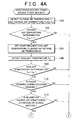
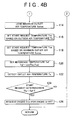
- FIGs. 4A and 4B schematically show the process when the heating power is maintained within the range in which a passenger does not feel uncomfortable.
- This flowchart is executed at predetermined time intervals when the ignition switch (not shown) of the vehicle is turned on, and the vehicle starts traveling.
- the outside air temperature To which is the temperature outside the vehicle
- the outside air temperature sensor 56 is detected by the outside air temperature sensor 56, and then, in step 102, it is determined, on the basis of the detected outside air temperature To, whether it is an environment under which the passenger compartment needs heating.
- FIG. 6A schematically shows an outside air temperature flag F TO used for the above determination.
- hysteresis is set between the temperatures To 1 and To 2 so that the temperature To 1 is higher than the temperature To 2 .
- the temperatures To 1 and To 2 at this time employ a typical outside air temperature To at which heating is required, and, for example, may set about 20°C for the temperature To 1 and about 15°C for the temperature To 2 .
- FIG. 6B shows an example of a start request coolant temperature Cw versus an outside air temperature To.
- the start request coolant temperature Cw is constant irrespective of the outside air temperature To; however, in the present embodiment, as the outside air temperature To increases, the start request coolant temperature Cw is decreased.
- the coolant temperature Tw at which a request for starting the engine 42 is issued starts request coolant temperature Cw
- start request coolant temperature Cw is increased.
- the start request coolant temperature Cw is decreased. This prevents the engine 42 from starting despite a situation that heating power is ensured.
- step 106 when the start request coolant temperature Cw, at which a request for starting the engine 42 is issued, is set on the basis of the outside air temperature To, the coolant temperature Tw inside the heater core 38 is detected by the coolant temperature sensor 62 in step 106, and it is checked in the next step 108 whether the coolant temperature Tw is lower than the start request coolant temperature Cw.
- the coolant temperature Tw is lower than the start request coolant temperature Cw (Tw ⁇ Cw)
- affirmative determination is made in step 108.
- step 110 it is checked in step 110 whether the engine 42 is stopped, that is, the economy running is performed. At this time, when the engine stop condition is satisfied and then the engine 42 is stopped, affirmative determination is made in step 110 to proceed to step 112.
- step 112 it is checked whether the blower motor 28 (blower fan 26) is turned on. That is, in step 112, it is checked whether the air conditioner 10 is performing air-conditioning operation (heating operation).
- step 112 when the air conditioner 10 is performing air-conditioning operation and the blower fan 26 is turned on, affirmative determination is made in step 112 to proceed to step 114.
- step 114 the maximum outlet air temperature Tamax is loaded.
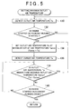
- FIG. 5 schematically shows the process of setting the maximum outlet air temperature Tamax. This flowchart is executed at predetermined time intervals in parallel with the process of FIGs. 4A and 4B when the air conditioner 10 performs air-conditioning operation. Note that the flowchart of FIG. 5 may also be, for example, executed in heating operation (air-conditioning operation in a heating mode), or the like.
- the outlet temperature Ta of conditioned air detected by the outlet air temperature sensor 68 is loaded.
- step 134 the outlet air temperature Ta detected by the outlet air temperature sensor 68 is set to the maximum outlet air temperature Tamax. That is, the outlet air temperature Ta detected by the outlet air temperature sensor 68 at the time when the economy running is started is set as an initial value of the maximum outlet air temperature Tamax.
- step 136 the outlet air temperature Ta detected by the outlet air temperature sensor 68 is loaded, and it is checked in step 138 whether the detected outlet air temperature Ta is higher than the maximum outlet air temperature Tamax. At this time, when the detected outlet air temperature Ta is higher than the maximum outlet air temperature Tamax that has been already set, affirmative determination is made in step 138 to proceed to step 136. Then, the maximum outlet air temperature Tamax is updated in step 136.
- an actual temperature of conditioned air may steeply increase.
- the outlet air temperature Ta output from the outlet air temperature sensor 68 is lower than the actual temperature.
- the air conditioner ECU 50 updates the maximum outlet air temperature Tamax (does not fix the outlet air temperature Ta to the initial value) when the outlet air temperature Ta detected by the outlet air temperature sensor 68 increases.
- Tamax the maximum outlet air temperature Tamax within the range from the time at which the economy running is started. That is, a request for starting the engine 42 is issued at the time when the outlet air temperature Ta, detected while the engine 42 is stopped, decreases from the maximum outlet air temperature Tamax by the allowable temperature ⁇ T.
- a request for starting the engine 42 is issued at the time when the outlet air temperature Ta, detected while the engine 42 is stopped, decreases from the maximum outlet air temperature Tamax by the allowable temperature ⁇ T.
- step 140 it is checked in step 140 whether the economy running is ended (whether the engine 42 is started), and, when the economy running is ended, affirmative determination is made in step 140 to temporarily end the process of setting the maximum outlet air temperature Tamax.
- step 112 when affirmative determination is made in step 112, the maximum outlet air temperature Tamax set in the process of FIG. 5 is loaded in step 114.
- step 116 a start request temperature Tso is set on the basis of the outside air temperature To detected by the outside air temperature sensor 56.
- FIG. 8A shows an example of the start request temperature Tso based on the outside air temperature To according to the present embodiment.
- the air conditioner ECU 50 stores a map, corresponding to FIG. 8A , of the start request temperature Tso based on the outside air temperature To, and sets the start request temperature Tso on the basis of the outside air temperature To using the map.
- the start request temperature Tso is set at a boundary temperature at which a passenger generally feels that it is not warm enough when conditioned air of that temperature blows out.
- the start request temperature Tso is set at a temperature Ca 1 ; however, when the outside air temperature To is a temperature To 4 that is lower than the temperature To 3 , the start request temperature Tso is set at a temperature Ca 2 that is higher than the temperature Ca 1 .
- the start request temperature Tso is set to a temperature Ca 3 between the temperature Ca 1 and the temperature Ca 2 (Ca 1 ⁇ Ca 3 ⁇ Ca 2 ). That is, when the outside air temperature To ranges from the temperature To 4 to the temperature To 3 , the start request temperature Tso decreases as the outside air temperature To increases.
- the start request temperature Tso based on the outside air temperature To is set in step 116, while a start request temperature Tsa based on the maximum outlet air temperature Tamax is set in step 118.
- ⁇ T 7°C
- start request temperature Tsa is not limited to this.
- the start request temperature Tsa may be set by changing the allowable temperature ⁇ T on the basis of the maximum outlet air temperature Tamax.
- FIG. 8B shows a start request temperature Tsa versus a maximum outlet air temperature Tamax according to the present embodiment.
- the air conditioner ECU 50 stores a map corresponding to FIG. 8B .
- the allowable temperature ⁇ T is increased as the maximum outlet air temperature Tamax increases.
- the start request temperature Tsa is set in this manner, when the maximum outlet air temperature Tamax is low, the allowable temperature ⁇ T is reduced to thereby make it possible to prevent the outlet air temperature Ta from excessively decreasing.
- the allowable temperature ⁇ T is increased to thereby make it possible to prevent the engine 42 from starting before the outlet air temperature Ta decreases.
- the reference temperature Taf at which a start request is issued, is set using the outlet air temperature Ta in step 120.
- the reference temperature Taf employs the lower one of the start request temperature Tso and the start request temperature Tsa.
- the outlet air temperature Ta detected by the outlet air temperature sensor 68 is loaded in step 122, and it is checked in step 124 whether the outlet air temperature Ta is lower than the reference temperature Taf.
- step 124 when heating operation is continued while the engine 42 is stopped, the coolant temperature Tw inside the heater core 38 decreases. Then, when the outlet air temperature Ta that decreases in accordance with the decrease in coolant temperature Tw is lower than the reference temperature Taf (Ta ⁇ Taf), affirmative determination is made in step 124 to proceed to step 126.
- step 126 a request for starting the engine 42 is issued to the engine ECU 64.
- the engine ECU 64 circulation of the coolant to the heater core 38 is started, while the coolant is heated by the engine 42.
- the outlet air temperature Ta which is a temperature of conditioned air that blows out into the passenger compartment, increases.
- the maximum outlet air temperature Tamax which is the highest outlet air temperature Ta during engine stop including the time when the engine stops, is used as a reference.
- the allowable temperature ⁇ T when the allowable temperature ⁇ T is subtracted from the maximum outlet air temperature Tamax to set the start request temperature Tsa, the allowable temperature ⁇ T is increased when the maximum outlet air temperature Tamax is high, while the allowable temperature ⁇ T is reduced when the maximum outlet air temperature Tamax is low.
- the target outlet air temperature T AO decreases to thereby decrease the maximum outlet air temperature Tamax.
- the allowable temperature ⁇ T is constant, there is a possibility that the engine 42 does not start despite a low outlet air temperature Ta.
- the outlet air temperature Ta at which a request for starting the engine 42 is issued, is determined using the lower one of the start request temperature Tso set on the basis of the outside air temperature To and the start request temperature Tsa set on the basis of the maximum outlet air temperature Tamax as the reference temperature Taf.
- the start request temperature Tso set on the basis of the outside air temperature To
- the start request temperature Tsa set on the basis of the maximum outlet air temperature Tamax as the reference temperature Taf.
- the air conditioner 10 when the passenger compartment is heated, the air conditioner 10 is able to improve fuel economy of the engine 42 and to reduce noise and emissions while reliably preventing a passenger from feeling uncomfortable.
- a coolant is circulated by the water pump 48 that is driven by the engine 42.
- a water pump that is driven by an electric motor hereinafter, referred to as motor pump
- motor pump an electric motor
- circulation of the coolant is stopped immediately after the engine is stopped, and, when the outlet air temperature Ta decreases, first, the motor pump is driven to start circulation of the coolant to perform heating operation using the coolant of which the temperature is maintained inside the engine 42, and then a request for starting the engine 42 is issued on the basis of the outlet air temperature Ta.
- both the water pump 48 and the motor pump may be used to circulate the coolant.
- the coolant may be circulated to the heater core 38 by the motor pump or the coolant may be circulated by the motor pump instead of the water pump 48 while the engine 42 is stopped.
- the present embodiment describes an example in which the air conditioner 10 that is able to perform cooling operation is employed as the vehicle heating system.
- the vehicle heating system to which the aspects of the invention are applied may be a configuration that does not have a cooling function.
Landscapes
- Engineering & Computer Science (AREA)
- Mechanical Engineering (AREA)
- Physics & Mathematics (AREA)
- Thermal Sciences (AREA)
- Chemical & Material Sciences (AREA)
- Combustion & Propulsion (AREA)
- General Engineering & Computer Science (AREA)
- Air-Conditioning For Vehicles (AREA)
- Output Control And Ontrol Of Special Type Engine (AREA)
- Control Of Vehicle Engines Or Engines For Specific Uses (AREA)
Abstract

Description
- The invention relates to a vehicle heating system that heats a passenger compartment by heated air generated using a coolant of an internal combustion engine.
- In a vehicle equipped with an internal combustion engine (hereinafter, referred to as engine) as a driving source for driving the vehicle, when the engine is idling (while the engine is driven at a minimum rotational speed; hereinafter, referred to as idle state), for example, at the time when the vehicle stops temporarily, the engine is stopped to execute engine control, such as economy running control or idle stop control (hereinafter, collectively referred to as economy running control), for reducing fuel consumption (improving fuel economy) and reducing emissions.
- In addition, a vehicle driven by the engine heats the passenger compartment using an engine coolant (for example, water; hereinafter, referred to as coolant). In a heating system (hereinafter, referred to as air conditioner), such as an air conditioning system, that heats the passenger compartment using a coolant, heat exchange takes place between air and the coolant heated by the engine to heat the air. Thus, conditioned air at a predetermined temperature is generated, and then the generated conditioned air blows out into the passenger compartment through an air outlet port, such as a foot air outlet port.
- Such an air conditioner is, for example, described in Japanese Patent Application Publication No.
1-223013 JP-A-1-223013 - In some air conditioners that not only heat the passenger compartment but also cool the passenger compartment, a compressor is driven by the engine and, therefore, cooling power decreases when the engine stops. In this state, for example, Japanese Patent Application Publication No.
10-246131 JP-A-10-246131 - Incidentally, the temperature of the coolant (coolant temperature) decreases when the engine is stopped, and then the heating power of the air conditioner decreases with the decrease in coolant temperature. For this reason, in the vehicle over which the economy running control is executed, the heating power decreases when the engine is stopped. This decreases the temperature of conditioned air blowing out into the passenger compartment, and possibly makes a passenger feel uncomfortable.
- In this state, for example, Japanese Patent Application Publication No.
2001-263123 JP-A-2001-263123 - In addition, for example, Japanese Patent Application Publication No.
2002-211238 JP-A-2002-211238 - Furthermore, for example, Japanese Patent Application Publication No.
2001-341515 JP-A-2001-341515 - However, when the temperature of the engine coolant is used as a reference, actually, there may be cases where the stop of the engine is prohibited despite heating power that does not make a passenger feel that it is not warm enough or the engine remains stopped despite heating power that makes a passenger to feel that it is not warm enough.
- The invention provides a vehicle heating system that does not make a passenger feel that it is not warm enough while preventing an internal combustion engine from being started unnecessarily during the economy running control, in which the internal combustion engine is stopped when a condition for stopping the internal combustion engine is satisfied, to improve fuel economy and reduce emissions.
- A first aspect of the invention provides a vehicle heating system. The vehicle heating system is provided for a vehicle that is equipped with an internal combustion engine as a driving source for driving the vehicle and that includes internal combustion engine control means that stops the internal combustion engine when a predetermined stop condition is satisfied and starts the internal combustion engine when a start condition is satisfied or on the basis of a start request. The vehicle heating system blows out heating air, heated using a coolant of the internal combustion engine, through an air outlet port to heat a passenger compartment. The vehicle heating system includes: outlet air temperature detecting means that detects an outlet air temperature, which is a temperature of the heating air that blows out through the air outlet port; first setting means that detects an outlet air temperature using the outlet air temperature detecting means at least at the time when the internal combustion engine stops, and that sets a first reference temperature that is lower by a predetermined allowable temperature than the detected outlet air temperature; and start request means that issues the start request for starting the internal combustion engine to the internal combustion engine control means when the outlet air temperature detected while the internal combustion engine is stopped is lower than the set first reference temperature.
- With the above configuration, the outlet air temperature is detected by the outlet air temperature detecting means at least at the time when the internal combustion engine stops, and the first reference temperature is set on the basis of the detected outlet air temperature and the allowable temperature. In addition, the start request means issues the start request for starting the internal combustion engine when the outlet air temperature detected while the internal combustion engine is stopped is lower than the first set temperature.
- Thus, the internal combustion engine is started to increase the outlet air temperature, and it is possible to reliably prevent a passenger from feeling uncomfortable.
- The vehicle heating system may further include outside air temperature detecting means that detects an outside air temperature, which is a temperature outside the vehicle; and second setting means that sets a second reference temperature on the basis of the detected outside air temperature, wherein the start request means may issue the start request for starting the internal combustion engine when the detected outlet air temperature is lower than the lower one of the first reference temperature and the second reference temperature.
- With the above configuration, the second reference temperature is set on the basis of the detected outside air temperature. At this time, the second reference temperature may be set to a lower limit value of an outlet air temperature (lowest outlet air temperature) at which a passenger does not feel uncomfortable.
- The start request means uses the lower one of the first reference temperature and the second reference temperature as a reference temperature and issues the start request for starting the internal combustion engine when the outlet air temperature is lower than the reference temperature. Thus, it is possible to reliably suppress a situation that the internal combustion engine is unnecessarily started. That is, it is possible to extend a duration during which the internal combustion engine is stopped.
- The first setting means may set the first reference temperature on the basis of a maximum outlet air temperature, which is a maximum temperature of the detected outlet air temperature during a period in which the internal combustion engine is stopped, including the time when the internal combustion engine stops.
- With the above configuration, the first reference temperature is set on the basis of the maximum outlet air temperature, which is the maximum temperature of the outlet air temperature during a period in which the internal combustion engine is stopped, including the time when the internal combustion engine stops. Thus, even when a delay in detection occurs in the outlet air temperature detecting means, it is possible to appropriately set the first reference temperature.
- Furthermore, the first reference temperature is set on the basis of the highest outlet air temperature detected while the internal combustion engine is stopped from the time when the internal combustion engine stops. Thus, it is possible to suppress a situation that a passenger feels that it is not warm enough.
- The first setting means may set the first reference temperature so that the allowable temperature is increased as the outlet air temperature used for setting the first reference temperature increases.
- With the above configuration, the allowable temperature is increased as the outlet air temperature increases to thereby decrease the first reference temperature with respect to the outlet air temperature. Thus, it is possible to prevent a situation that the internal combustion engine is started despite a high outlet air temperature or a situation that the internal combustion engine is not started despite a low outlet air temperature.
- A second aspect of the invention provides a method of heating a passenger compartment by blowing out heating air, heated by a coolant of an internal combustion engine, through an air outlet port, wherein the internal combustion engine is stopped when a predetermined stop condition is satisfied, and the internal combustion engine is started when a start condition is satisfied or on the basis of a start request. The method includes the steps of: detecting an outlet air temperature, which is a temperature of the heating air that blows out through the air outlet port; detecting the outlet air temperature at least at the time when the internal combustion engine stops and then setting a first reference temperature that is lower by a predetermined allowable temperature than the detected outlet air temperature; and issuing the start request for starting the internal combustion engine to the internal combustion engine control means when the outlet air temperature detected while the internal combustion engine is stopped is lower than the set first reference temperature.
- As described above, according to the aspects of the invention, the first reference temperature is set on the basis of the outlet air temperature at least at the time when the internal combustion engine stops, and the start request for starting the internal combustion engine is issued when the outlet air temperature is lower than the first reference temperature. Thus, it is advantageous in that the internal combustion engine is not unnecessarily started and also it is possible to prevent a passenger from feeling that it is not warm enough.
- The features, advantages, and technical and industrial significance of this invention will be described in the following detailed description of example embodiments of the invention with reference to the accompanying drawings, in which like numerals denote like elements, and wherein:
-
FIG. 1 is a schematic configuration of a relevant portion of an air conditioner, which serves as a vehicle heating system, according to an embodiment; -
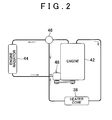
FIG. 2 is a schematic configuration diagram of a relevant portion that shows a coolant circulation system; -
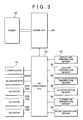
FIG. 3 is a block diagram that shows a relevant portion of a control system of the air conditioner and an engine; -
FIGs. 4A and4B show a flowchart that schematically shows an engine start request control; -
FIG. 5 is a flowchart that shows an example of setting a maximum outlet air temperature; -
FIG. 6A is a chart that schematically shows setting and resetting of an outside air temperature flag; -
FIG. 6B is a map that shows an example of an engine start request coolant temperature versus an outside air temperature; -
FIG. 7 is a chart that shows an example of an outlet air temperature at the time when the engine stops and a variation in outlet air temperature detected by an outlet air temperature sensor; -
FIG. 8A is a map that shows an example of a start request temperature based on an outside air temperature; and -
FIG. 8B is a map that shows an example of a start request temperature versus a maximum outlet air temperature. - Hereinafter, an embodiment of the invention will be described with reference to the accompanying drawings.
FIG. 1 shows the schematic configuration of a vehicle air conditioning system (hereinafter, referred to as air conditioner 10), which serves as a vehicle heating system, according to the present embodiment. - The
air conditioner 10 has a refrigeration cycle in which a refrigerant is circulated. The refrigeration cycle is formed of acompressor 12, acondenser 14, anexpansion valve 16 and anevaporator 18. In theair conditioner 10, a refrigerant is compressed by thecompressor 12 being driven for rotation, the obtained high-temperature and high-pressure refrigerant is transferred to thecondenser 14, and then cooled and liquefied. - The liquefied refrigerant is fed to the
evaporator 18 and then evaporated. At this time, in theevaporator 18, heat exchange takes place between the refrigerant to be evaporated and air that passes through theevaporator 18. Thus, in theair conditioner 10, the air that passes through theevaporator 18 is cooled and dehumidified. Theexpansion valve 18 steeply reduces the pressure of the refrigerant fed to theevaporator 18 to form the misty refrigerant to thereby improve the vaporization efficiency of the refrigerant at the evaporator 18 (cooling efficiency at the evaporator 18). - The
air conditioner 10 includes anair conditioner unit 20 in which a passage of conditioned air is formed. Theevaporator 18 is arranged inside theair conditioner unit 20. In addition, theair conditioner unit 20 hasair introducing ports 22 formed at one end of the passage of conditioned air, and outlet ports of conditioned air are connected to the other end of theair conditioner unit 20. - The
air conditioner 10 has set an inside air circulating mode and an outside air introducing mode as an air introducing mode. Air inside the passenger compartment is introduced in the inside air circulating mode. Outside air is introduced in the outside air introducing mode. Theair conditioner unit 20 has an insideair introducing port 22A and an outsideair introducing port 22B as the introducingports 22. The insideair introducing port 22A is open to the passenger compartment. The outsideair introducing port 22B is open to the outside of the passenger compartment. In addition, theair conditioner unit 20 is provided with a switchingdoor 24 and ablower fan 26. The switchingdoor 24 opens or closes the insideair introducing port 22A and the outsideair introducing port 22B. - In the
air conditioner 10, in accordance with the air introducing mode, the switchingdoor 24 is actuated to open or close the insideair introducing port 22A and the outsideair introducing port 22B, and air introduced from the introducing port 22 (the insideair introducing port 22A or the outsideair introducing port 22B) to theevaporator 18 by theblower fan 26 that is driven for rotation by ablower motor 28. - The
air conditioner 10 has defroster air outlet ports 30 (for example, a center defroster air outlet port 30A and side defrosterair outlet ports 30B), register air outlet ports 32 (for example, center registerair outlet ports 32A and side registerair outlet ports 32B) and foot air outlet ports 34 (for example, front seat footair outlet ports 34A that are open to spaces around the feet of passengers on the front seat, and rear seat footair outlet ports 34B that are open to spaces around the feed of passengers on the rear seat), as air outlet ports of conditioned air. The defrosterair outlet ports 30 are open toward windshield glasses (not shown). The registerair outlet ports 32 are open toward passengers inside the passenger compartment. The footair outlet ports 34 are open toward the feet of passengers. - The
air conditioner unit 20 includesmode switching doors 36. Themode switching doors 36 are respectively in fluid communication with the defrosterair outlet ports 30, the registerair outlet ports 32 and the footair outlet ports 34, and respectively open or close the defrosterair outlet ports 30, the registerair outlet ports 32 and the footair outlet ports 34. - The
air conditioner 10 has set a DEF mode, a FACE mode, a FOOT mode, a FOOT/DEF mode and a BI-LEVEL mode, as outlet modes of conditioned air. Conditioned air blows out through the defrosterair outlet ports 30 in the DEF mode. Conditioned air blows out through the registerair outlet ports 32 in the FACE mode. Conditioned air blows out through the footair outlet ports 34 in the FOOT mode. Conditioned air blows out through the defrosterair outlet ports 30 and the footair outlet ports 34 in the FOOT/DEF mode. Conditioned air blows out through the registerair outlet ports 32 and the footair outlet port 34 in the BI-LEVEL mode. In theair conditioner 10, once the outlet mode is set, themode switching doors 36 are actuated on the basis of the set outlet mode, and conditioned air blows out through the air outlet ports based on the air outlet mode. - In addition, the
air conditioner unit 20 includes aheater core 38 and anair mix door 40. In theair conditioner 10, air that passes through theevaporator 18 can pass through theheater core 38, and the air that passes through theheater core 38 is heated by theheater core 38. - In the
air conditioner 10, heated air passing through theheater core 38 is mixed with air bypassing theheater core 38 to generate conditioned air. At this time, theair conditioner 10 controls the amount of air passing through theheater core 38 and the amount of air bypassing theheater core 38 by the opening degree S of theair mix door 40 to generate conditioned air at a desired temperature. Thus, the opening degree S of theair mix door 40 is increased to generate heated air that heats the passenger compartment as conditioned air. - On the other hand, as shown in
FIG. 2 , a vehicle equipped with theair conditioner 10 includes anengine 42 as an internal combustion engine, and theengine 42 is driven for driving the vehicle. Theengine 42 is a typical water-cooled internal combustion engine that uses water (hereinafter, referred to as coolant) as an engine coolant. - The vehicle has a coolant circuit formed of an
engine radiator 44, athermostat 46 and awater pump 48 to circulate coolant between theengine 42 and theengine radiator 44. In the present embodiment, thewater pump 48 is driven by theengine 42 for rotation, and thewater pump 48 is driven for rotation to circulate coolant between theengine 42 and theengine radiator 44. - Air present in front of the vehicle is introduced to the
engine radiator 44 as the vehicle runs or as a cooling fan (not shown) operates. In theengine radiator 44, heat exchange takes place between the air and the coolant to cool the coolant, and the coolant is circulated back to theengine 42. Thus, it is possible to suppress an increase in temperature of theengine 42 due to exhaust heat. - The
thermostat 46 opens or closes the passage of the coolant to theengine radiator 44 on the basis of a temperature of the coolant (coolant temperature) to maintain the coolant temperature within a predetermined temperature range while theengine 42 is in operation. That is, when the coolant temperature Tw is higher than a predetermined temperature T1, thethermostat 46 fully opens the passage of the coolant to theengine radiator 44 to facilitate cooling of the coolant. In addition, when the coolant temperature Tw is lower than the temperature T1, thethermostat 46 gradually narrows the passage to theengine radiator 44 and, when the coolant temperature Tw reaches a temperature T2 (T1 > T2), closes the passage to theengine radiator 44 to suppress cooling of the coolant. Thus, while theengine 44 is in operation, the coolant temperature Tw is maintained at a predetermined temperature Ts within the range from the temperature T1 to the temperature T2 (T2 < Ts < T1). Note that it is only necessary that the vehicle includes an internal combustion engine as a driving source for driving the vehicle, and the vehicle is not limited to a so-called conventional vehicle that runs only by driving force of an internal combustion engine. Instead, the vehicle may be a hybrid vehicle that is equipped with an electric motor in addition to an internal combustion engine. - On the other hand, the coolant of the
engine 42 is circulated to theheater core 38 of theair conditioner 10 as thewater pump 48 is driven. In theair conditioner 10, the coolant is circulated to theheater core 38 to cause heat exchange to take place between air passing through theheater core 38 and the coolant. Thus, in theair conditioner 10, air is heated by theheater core 38. - As shown in
FIG. 3 , theair conditioner 10 includes anair conditioner ECU 50 that controls air-conditioning operation. Theair conditioner ECU 50 has a typical configuration including a microcomputer in which a CPU, a ROM, a RAM, and the like, are connected through a bus, various input/output interfaces and various driving circuits (all of which are not shown). - The
compressor 12 is connected to theair conditioner ECU 50. Theair conditioner ECU 50 controls the refrigerant discharge capacity of thecompressor 12 on the basis of a cooling load. Note that thecompressor 12 may be the one that is driven by theengine 42 for rotation or may be the one that is driven for rotation by an electric motor (compressor motor). - The
blower motor 28 is connected to theair conditioner ECU 50. Theair conditioner ECU 50 controls the volume of conditioned air supplied (blower volume) in such a manner that the rotational speed of theblower fan 26 is controlled by driving theblower motor 28. - In addition, the
air conditioner ECU 50 is connected to anactuator 52A that actuates the switchingdoor 24, anactuator 52B that actuates themode switching doors 36, and anactuator 52C that actuates theair mix door 40. Theair conditioner ECU 50 actuates theactuators actuator 52C so as to obtain the conditioned air that makes the passenger compartment at a set temperature. - The
air conditioner ECU 50 is connected to aroom temperature sensor 54, an outsideair temperature sensor 56, asolar radiation sensor 58, apost-evaporation temperature sensor 60, acoolant temperature sensor 62, and the like. Theroom temperature sensor 54 detects a temperature in the passenger compartment (compartment temperature Tr). The outsideair temperature sensor 56 detects a temperature outside the vehicle (outside air temperature To). Thesolar radiation sensor 58 detects a solar radiation ST. Thepost-evaporation temperature sensor 60 detects a temperature of air that has passed through the evaporator 18 (post-evaporation temperature Te). Thecoolant temperature sensor 62 detects a temperature Tw of the coolant of theengine 42, that passes through theheater core 38. - When the operating condition, such as a set temperature, is set by operating a switch of an operating panel (not shown), the
air conditioner ECU 50 detects the environmental condition and operation state by those sensors, and performs air-conditioning operation so that the passenger compartment is at the set temperature on the basis of the operating condition, the environmental condition and the operating state. - At this time, the
air conditioner ECU 50, for example, sets a target outlet air temperature TAO, which is a temperature of conditioned air necessary to make the passenger compartment at a set temperature TSET. The target outlet air temperature TAO may be calculated by a known typical arithmetic expression.
- The
air conditioner ECU 50 controls the opening degree of theair mix door 40 on the basis of the target outlet air temperature TAO. In addition, when air-conditioning operation in an automatic mode is set, theair conditioner ECU 50 sets the blower volume, conditioned air outlet mode, and the like, on the basis of the target outlet air temperature TAO. - For example, the compartment temperature Tr, the set temperature TSET, or the like, is used as a reference temperature, and the blower volume is set on the basis of a difference between the reference temperature and the target outlet air temperature TAO. At this time, the blower volume is reduced when the difference between the reference temperature and the target outlet air temperature TAO is small, and the blower volume is increased as the difference between the reference temperature and the target outlet air temperature TAO increases.
- Generally, the conditioned air outlet mode is set to the FACE mode when in a heating mode in which the set temperature TSET or the target outlet air temperature TAO is lower than the compartment temperature Tr, and is set to the FOOT mode or the BI-LEVEL mode when in a heating mode in which the set temperature TSET or the target outlet air temperature TAO is higher than the compartment temperature Tr.
- The
air conditioner ECU 50 performs air-conditioning operation that makes the passenger compartment at the set temperature TSET on the basis of the thus set operating condition. Note that the basic configuration of an air-conditioning control executed by theair conditioner ECU 50 may employ a known configuration, so the detailed description thereof is omitted here. - On the other hand, the vehicle is provided with an
engine ECU 64 that controls theengine 42. Theengine ECU 64 has a typical configuration including a microcomputer in which a CPU, a ROM, a RAM, and the like, are connected through a bus, various input/output interfaces and various driving circuits (all of which are not shown). Theengine ECU 64 detects a driving operation condition, running environment, running state, and the like, of the vehicle through various sensors, and the like (not shown), and controls theengine 42 so as to drive the vehicle appropriately. At this time, theengine ECU 64 applied to the present embodiment executes economy running control such that theengine 42 is started when a predetermined engine start condition is satisfied and theengine 42 is stopped when a predetermined engine stop condition is satisfied. - Thus, the vehicle, for example, performs an idle stop in which the
engine 42 is stopped when the vehicle is not running (the vehicle speed is zero). Theengine ECU 64 executes the economy running control over theengine 42 to improve fuel economy and suppress noise and emissions. Note that the basic configuration of a driving control of theengine 42, executed by theengine ECU 64, may employ a known typical configuration, so the detailed description thereof is omitted here. - Incidentally, when the
engine ECU 64 receives a request for starting the engine 42 (engine start request) from theair conditioner ECU 50 while theengine 42 is stopped in a state where the engine stop condition is satisfied (economy running), theengine ECU 64 starts theengine 42 on the basis of the engine start request. - The
air conditioner 10 has an outletair temperature sensor 68, which serves as outlet air temperature detecting means, in aduct 66 at which the footair outlet ports 34 are formed. Conditioned air blows out through the footair outlet ports 34 when air-conditioning operation is performed in a heating mode. - Generally, when air-conditioning operation is performed in the heating mode, conditioned air mainly blows out through the foot
air outlet ports 34. This provides a comfortable heating feeling. In this state, when air-conditioning operation is performed in the heating mode, the outletair temperature sensor 68 detects a temperature of conditioned air that blows out through the footair outlet ports 34. Note that the outletair temperature sensor 68 may be provided at a selected location as long as the outletair temperature sensor 68 is able to detect the temperature of conditioned air that blows out into the passenger compartment when air-conditioning operation is performed in the heating mode. - As shown in
FIG. 3 , the outletair temperature sensor 68 is connected to theair conditioner ECU 50. Theair conditioner ECU 50 detects the temperature of conditioned air that blows out through the foot air outlet ports 34 (hereinafter, referred to as outlet air temperature Ta) by the outletair temperature sensor 68. - The
air conditioner ECU 50 sets the opening degree S of theair mix door 40 on the basis of the coolant temperature Tw detected by thecoolant temperature sensor 62, and actuates theactuator 52C so as to obtain the set opening degree S. - For example, where the ratio of the volume of air passing through the
heater core 38 to the volume of all the air (blower volume) is expressed as the mixing ratio r, the opening degree S of theair mix door 40 is obtained from a mixing ratio r. The mixing ratio r is obtained from the post-evaporation temperature Te, the temperature of air passing through the heater core 38 (post-heater core temperature Th) and the target outlet air temperature TAO.
- At this time, the post-evaporation temperature Te may be detected by the
post-evaporation temperature sensor 60, and the post-heater core temperature Th may be detected by providing a temperature sensor downstream of theheater core 38. In addition, the post-heater core temperature Th may be obtained on the basis of the temperature Tw and flow rate (the rotational speed of thewater pump 48, that is, the rotational speed of the engine 42) of coolant supplied to theheater core 38 and the temperature efficiency that is determined depending on theheater core 38. In theair conditioner 10, when the opening degree S of theair mix door 40 is maximal, cooling power is maximal at the coolant temperature Tw at that moment. - On the other hand, while the
engine 42 is stopped, a decrease in coolant temperature occurs to no small extent. The heating power of theair conditioner 10 decreases as the coolant temperature Tw decreases. Therefore, even when theair mix door 40 is set to the maximum opening degree, conditioned air of a temperature that gives the target outlet air temperature TAO cannot be obtained. Thus, a passenger may feel that it is not warm enough. - Here, while the
engine 42 is stopped, theair conditioner ECU 50 determines a variation in heating power on the basis of the outlet temperature Ta of conditioned air detected by the outletair temperature sensor 68 during heating operation and then issues a request for starting theengine 42, thus preventing a passenger from feeling that it is not warm enough. - At this time, the
air conditioner ECU 50 determines, on the basis of the outside air temperature To detected by the outsideair temperature sensor 56, whether the environmental state (outside air temperature) needs heating in the passenger compartment. - The
air conditioner ECU 50 has a set lower limit value of the coolant temperature Tw with respect to the outside air temperature To (hereinafter referred to as reference temperature Tso) when the stop of theengine 42 is allowed, as a second reference temperature. - In addition, the
air conditioner ECU 50 detects the maximum temperature of the outlet air temperature Ta (maximum outlet air temperature Tamax) after the stop of the engine (economy running) is started, and sets the lower limit value of the outlet air temperature Ta (hereinafter, referred to as reference temperature Tsa) when the stop of the engine is allowed on the basis of the maximum outlet air temperature Tamax, as a first reference temperature. The reference temperature Tsa is set at a temperature that is lower by a predetermined allowable temperature ΔT than the maximum outlet air temperature Tamax. - When the economy running (stop of the engine) is started, the
air conditioner ECU 50 sets the lower one of the reference temperatures Tso and Tsa to the reference temperature Taf at which an engine start request is issued on the basis of the outlet air temperature Ta. When the outlet temperature Ta of conditioned air detected by the outletair temperature sensor 68 is lower than the reference temperature Taf, theair conditioner ECU 50 issues an engine start request to theengine ECU 64. - Thus, when the
engine 42 is started, the coolant is heated by theengine 42, and an increase in heating power is achieved by the heated coolant being circulated to theheater core 38. - Hereinafter, maintaining the heating power in such a manner that the air conditioner 10 (air conditioner ECU 50) issues an engine start request will be described as an operation of the present embodiment.
- When the
air conditioner ECU 50 provided in theair conditioner 10 receives an instruction for starting the air-conditioning operation, theair conditioner ECU 50 loads the operating condition, such as the set temperature TSET, and the environmental condition, such as the compartment temperature Tr and the outside air temperature To, and then sets the target outlet air temperature TAO, which makes the passenger compartment at the set temperature, on the basis of the operating condition, the environmental condition and the operating state. - In addition, the
air conditioner ECU 50 sets the introducing mode, the blower volume and the air outlet mode on the basis of the operating condition input from the operating panel or the operating condition set on the basis of the target outlet air temperature TAO, and then starts air-conditioning operation so that conditioned air blows out at the target outlet air temperature TAO. That is, theair conditioner ECU 50 controls the opening degree S of theair mix door 40 to make the passenger compartment at the set temperature TSET, thus performing air-conditioning operation. - On the other hand, when an ignition switch (not shown) is turned on and then the vehicle starts running, the
engine ECU 64 detects the driving operation condition, the running environment, the operating state, and the like, and then executes driving control over theengine 42 on the basis of the detected information. Thus, the vehicle runs in response to passenger's driving operation. - At this time, when the predetermined engine stop condition is satisfied, the
engine ECU 64 executes economy running in which theengine 42 is stopped to thereby improve fuel economy and suppress noise and emissions. - Incidentally, by executing economy running in which the
engine 42 is stopped, circulation of the coolant to theheater core 38 stops and, therefore, the heating power of theair conditioner 10 decreases. If the heating power of theair conditioner 10 excessively decreases, the temperature of conditioned air that blows out into the passenger compartment (outlet air temperature Ta) decreases. This may make a passenger feel uncomfortable. - In this state, when the heating power decreases, the
air conditioner ECU 50 issues a request for starting theengine 42 at an appropriate timing, thus preventing the passenger from feeling uncomfortable. - Here, the process in the
air conditioner ECU 50 will be described with reference toFIGs. 4A to FIG 8B .FIGs. 4A and4B schematically show the process when the heating power is maintained within the range in which a passenger does not feel uncomfortable. This flowchart is executed at predetermined time intervals when the ignition switch (not shown) of the vehicle is turned on, and the vehicle starts traveling. In thefirst step 100, the outside air temperature To, which is the temperature outside the vehicle, is detected by the outsideair temperature sensor 56, and then, instep 102, it is determined, on the basis of the detected outside air temperature To, whether it is an environment under which the passenger compartment needs heating. -
FIG. 6A schematically shows an outside air temperature flag FTO used for the above determination. The outside air temperature flag FTO is set (FTO = 1) when the outside air temperature To decreases to a temperature To2, and is reset (FTO = 0) when the outside air temperature To increases to a temperature To1. Here, hysteresis is set between the temperatures To1 and To2 so that the temperature To1 is higher than the temperature To2. - The temperatures To1 and To2 at this time employ a typical outside air temperature To at which heating is required, and, for example, may set about 20°C for the temperature To1 and about 15°C for the temperature To2. By so doing, in a state where the outside air temperature flag FTO is set (FTO = 1), it may be determined that it is the environment under which heating operation of the
air conditioner 10 is required. - In the flowchart of
FIGs. 4A and4B , when the outside air temperature To detected by the outsideair temperature sensor 56 is in an environmental state where heating operation is required (FTO = 1), affirmative determination is made instep 102, and, instep 104, a start request coolant temperature Cw, at which a request for starting theengine 42 is issued, is set on the basis of the outside air temperature To. -
FIG. 6B shows an example of a start request coolant temperature Cw versus an outside air temperature To. Generally, the start request coolant temperature Cw is constant irrespective of the outside air temperature To; however, in the present embodiment, as the outside air temperature To increases, the start request coolant temperature Cw is decreased. Thus, when it is assumed that the outside air temperature To is low and, therefore, high heating power is required, the coolant temperature Tw at which a request for starting theengine 42 is issued (start request coolant temperature Cw) is increased. As the outside air temperature To increases, the start request coolant temperature Cw is decreased. This prevents theengine 42 from starting despite a situation that heating power is ensured. - In
FIGs. 4A and4B , when the start request coolant temperature Cw, at which a request for starting theengine 42 is issued, is set on the basis of the outside air temperature To, the coolant temperature Tw inside theheater core 38 is detected by thecoolant temperature sensor 62 instep 106, and it is checked in thenext step 108 whether the coolant temperature Tw is lower than the start request coolant temperature Cw. Here, when the coolant temperature Tw is lower than the start request coolant temperature Cw (Tw < Cw), affirmative determination is made instep 108. - When the affirmative determination is made in
step 108, it is checked instep 110 whether theengine 42 is stopped, that is, the economy running is performed. At this time, when the engine stop condition is satisfied and then theengine 42 is stopped, affirmative determination is made instep 110 to proceed to step 112. - In
step 112, it is checked whether the blower motor 28 (blower fan 26) is turned on. That is, instep 112, it is checked whether theair conditioner 10 is performing air-conditioning operation (heating operation). - Here, when the
air conditioner 10 is performing air-conditioning operation and theblower fan 26 is turned on, affirmative determination is made instep 112 to proceed to step 114. Instep 114, the maximum outlet air temperature Tamax is loaded. -
FIG. 5 schematically shows the process of setting the maximum outlet air temperature Tamax. This flowchart is executed at predetermined time intervals in parallel with the process ofFIGs. 4A and4B when theair conditioner 10 performs air-conditioning operation. Note that the flowchart ofFIG. 5 may also be, for example, executed in heating operation (air-conditioning operation in a heating mode), or the like. - In the above flowchart, in the
first step 130, the outlet temperature Ta of conditioned air detected by the outletair temperature sensor 68 is loaded. In addition, in thenext step 132, it is checked whether the engine stop condition is satisfied and then theengine 42 is stopped. - Here, when the
engine 42 is stopped to start the economy running, affirmative determination is made instep 132 to proceed to step 134. Instep 134, the outlet air temperature Ta detected by the outletair temperature sensor 68 is set to the maximum outlet air temperature Tamax. That is, the outlet air temperature Ta detected by the outletair temperature sensor 68 at the time when the economy running is started is set as an initial value of the maximum outlet air temperature Tamax. - After that, in
step 136, the outlet air temperature Ta detected by the outletair temperature sensor 68 is loaded, and it is checked instep 138 whether the detected outlet air temperature Ta is higher than the maximum outlet air temperature Tamax. At this time, when the detected outlet air temperature Ta is higher than the maximum outlet air temperature Tamax that has been already set, affirmative determination is made instep 138 to proceed to step 136. Then, the maximum outlet air temperature Tamax is updated instep 136. - That is, as shown in
FIG. 7 , when the economy running is started (when the engine shifts from a driving state into a stopped state), an actual temperature of conditioned air (indicated by the broken line inFIG. 7 ) may steeply increase. At this time, when an increase in temperature of the sensing portion of the outletair temperature sensor 68 delays, the outlet air temperature Ta output from the outletair temperature sensor 68 is lower than the actual temperature. - For this reason, when the engine start request is issued at the time when the outlet air temperature Ta decreases by the allowable temperature ΔT using the outlet air temperature Ta at the time of starting the economy running as a reference, start of the
engine 42 delays to thereby make a passenger feel that it is not warm enough. - In contrast, the
air conditioner ECU 50 updates the maximum outlet air temperature Tamax (does not fix the outlet air temperature Ta to the initial value) when the outlet air temperature Ta detected by the outletair temperature sensor 68 increases. Thus, it is possible to appropriately set the maximum outlet air temperature Tamax within the range from the time at which the economy running is started. That is, a request for starting theengine 42 is issued at the time when the outlet air temperature Ta, detected while theengine 42 is stopped, decreases from the maximum outlet air temperature Tamax by the allowable temperature ΔT. Thus, it is possible to start theengine 42 before a passenger feels that it is not warm enough. - Note that in the flowchart of
FIG. 5 , it is checked instep 140 whether the economy running is ended (whether theengine 42 is started), and, when the economy running is ended, affirmative determination is made instep 140 to temporarily end the process of setting the maximum outlet air temperature Tamax. - On the other hand, in the flowchart of
FIGs. 4A and4B , when affirmative determination is made instep 112, the maximum outlet air temperature Tamax set in the process ofFIG. 5 is loaded instep 114. In addition, in step 116, a start request temperature Tso is set on the basis of the outside air temperature To detected by the outsideair temperature sensor 56. -
FIG. 8A shows an example of the start request temperature Tso based on the outside air temperature To according to the present embodiment. Theair conditioner ECU 50 stores a map, corresponding toFIG. 8A , of the start request temperature Tso based on the outside air temperature To, and sets the start request temperature Tso on the basis of the outside air temperature To using the map. - The start request temperature Tso is set at a boundary temperature at which a passenger generally feels that it is not warm enough when conditioned air of that temperature blows out. When the outside air temperature To is higher than a temperature To3, the start request temperature Tso is set at a temperature Ca1; however, when the outside air temperature To is a temperature To4 that is lower than the temperature To3, the start request temperature Tso is set at a temperature Ca2 that is higher than the temperature Ca1.
- In addition, when the outside air temperature To is a temperature To5 between the temperature To4 and the temperature To3 (To4 < To5 < To3), the start request temperature Tso is set to a temperature Ca3 between the temperature Ca1 and the temperature Ca2 (Ca1 < Ca3 < Ca2). That is, when the outside air temperature To ranges from the temperature To4 to the temperature To3, the start request temperature Tso decreases as the outside air temperature To increases.
- In the flowchart of
FIGs. 4A and4B , the start request temperature Tso based on the outside air temperature To is set in step 116, while a start request temperature Tsa based on the maximum outlet air temperature Tamax is set instep 118. - The start request temperature Tsa may be set as a temperature that is obtained by subtracting a predetermined allowable temperature ΔT (for example, ΔT = 7°C) from the maximum outlet air temperature Tamax uniformly (Tsa = Tamax - ΔT).
- In addition, the start request temperature Tsa is not limited to this. The start request temperature Tsa may be set by changing the allowable temperature ΔT on the basis of the maximum outlet air temperature Tamax.
FIG. 8B shows a start request temperature Tsa versus a maximum outlet air temperature Tamax according to the present embodiment. Theair conditioner ECU 50 stores a map corresponding toFIG. 8B . - As shown in
FIG. 8B , in the present embodiment, the allowable temperature ΔT is increased as the maximum outlet air temperature Tamax increases. By setting the start request temperature Tsa in this manner, when the maximum outlet air temperature Tamax is low, the allowable temperature ΔT is reduced to thereby make it possible to prevent the outlet air temperature Ta from excessively decreasing. - In addition, as the maximum outlet air temperature Tamax increases, the allowable temperature ΔT is increased to thereby make it possible to prevent the
engine 42 from starting before the outlet air temperature Ta decreases. - In the flowchart of
FIGs. 4A and4B , when the start request temperatures Tso and Tsa are set, the reference temperature Taf, at which a start request is issued, is set using the outlet air temperature Ta instep 120. The reference temperature Taf employs the lower one of the start request temperature Tso and the start request temperature Tsa. - After that, the outlet air temperature Ta detected by the outlet
air temperature sensor 68 is loaded instep 122, and it is checked instep 124 whether the outlet air temperature Ta is lower than the reference temperature Taf. - Here, when heating operation is continued while the
engine 42 is stopped, the coolant temperature Tw inside theheater core 38 decreases. Then, when the outlet air temperature Ta that decreases in accordance with the decrease in coolant temperature Tw is lower than the reference temperature Taf (Ta < Taf), affirmative determination is made instep 124 to proceed to step 126. - In
step 126, a request for starting theengine 42 is issued to theengine ECU 64. By so doing, when theengine 42 is driven, circulation of the coolant to theheater core 38 is started, while the coolant is heated by theengine 42. As a result, the outlet air temperature Ta, which is a temperature of conditioned air that blows out into the passenger compartment, increases. - In this way, in the
air conditioner 10, when a request for starting theengine 42 is issued on the basis of the outlet air temperature Ta, the maximum outlet air temperature Tamax, which is the highest outlet air temperature Ta during engine stop including the time when the engine stops, is used as a reference. Thus, it is possible to prevent the outlet air temperature Ta from excessively decreasing to make a passenger feel that it is not warm enough before issuance of a request for starting theengine 42 because of a delay of detection of the outletair temperature sensor 68. - In addition, in the present embodiment, when the allowable temperature ΔT is subtracted from the maximum outlet air temperature Tamax to set the start request temperature Tsa, the allowable temperature ΔT is increased when the maximum outlet air temperature Tamax is high, while the allowable temperature ΔT is reduced when the maximum outlet air temperature Tamax is low.
- Thus, it is possible to issue a request for starting the
engine 42 at an appropriate timing. That is, when a difference between the set temperature TSET and the compartment temperature Tr is large, the target outlet air temperature TAO increases to thereby increase the maximum outlet air temperature Tamax. However, if the allowable temperature ΔT is constant, there is a possibility that theengine 42 starts despite a high outlet air temperature Ta. - In addition, when a difference between the set temperature TSET and the compartment temperature Tr is small, the target outlet air temperature TAO decreases to thereby decrease the maximum outlet air temperature Tamax. However, at this time, when the allowable temperature ΔT is constant, there is a possibility that the
engine 42 does not start despite a low outlet air temperature Ta. - In contrast, as the maximum outlet air temperature Tamax increases, the allowable temperature ΔT is increased and then the start request temperature Tsa is set. Thus, it is possible to issue a request for starting the
engine 42 at an appropriate timing. - On the other hand, in the
air conditioner 10, the outlet air temperature Ta, at which a request for starting theengine 42 is issued, is determined using the lower one of the start request temperature Tso set on the basis of the outside air temperature To and the start request temperature Tsa set on the basis of the maximum outlet air temperature Tamax as the reference temperature Taf. Thus, it is possible to suppress a situation in which theengine 42 is started before the outlet air temperature Ta decreases to thereby extend a duration during which theengine 42 is stopped. - Hence, when the passenger compartment is heated, the
air conditioner 10 is able to improve fuel economy of theengine 42 and to reduce noise and emissions while reliably preventing a passenger from feeling uncomfortable. - Note that the above described present embodiment does not intend to limit the configuration of the aspects of the invention. For example, in the present embodiment, a coolant is circulated by the
water pump 48 that is driven by theengine 42. Instead, a water pump that is driven by an electric motor (hereinafter, referred to as motor pump) may also be used. - In this case, when the
engine 42 is stopped, the motor pump is driven so that the coolant is circulated at a flow rate corresponding to a request from theair conditioner ECU 50. Thus, it is possible to suppress a decrease in outlet air temperature Ta to extend a duration during which theengine 42 is stopped. - In addition, it is also applicable that circulation of the coolant is stopped immediately after the engine is stopped, and, when the outlet air temperature Ta decreases, first, the motor pump is driven to start circulation of the coolant to perform heating operation using the coolant of which the temperature is maintained inside the
engine 42, and then a request for starting theengine 42 is issued on the basis of the outlet air temperature Ta. - In addition, both the
water pump 48 and the motor pump may be used to circulate the coolant. In this case, for example, the coolant may be circulated to theheater core 38 by the motor pump or the coolant may be circulated by the motor pump instead of thewater pump 48 while theengine 42 is stopped. - In addition, the present embodiment describes an example in which the
air conditioner 10 that is able to perform cooling operation is employed as the vehicle heating system. Instead, the vehicle heating system to which the aspects of the invention are applied may be a configuration that does not have a cooling function.
Claims (7)
- A vehicle heating system provided for a vehicle that is equipped with an internal combustion engine (42) as a driving source for driving the vehicle and that includes internal combustion engine control means (64) that stops the internal combustion engine when a predetermined stop condition is satisfied and starts the internal combustion engine when a start condition is satisfied or on the basis of a start request, wherein the vehicle heating system blows out heating air, heated using a coolant of the internal combustion engine, through an air outlet port (30, 32, 34) to heat a passenger compartment, the vehicle heating system comprising:outlet air temperature detecting means (68) that detects an outlet air temperature, which is a temperature of the heating air that blows out through the air outlet port (30, 32, 34);first setting means (50) that detects an outlet air temperature using the outlet air temperature detecting means at least at the time when the internal combustion engine stops, and that sets a first reference temperature (Tsa) that is lower by a predetermined allowable temperature (ΔT) than the detected outlet air temperature; andstart request means (50) that issues the start request for starting the internal combustion engine to the internal combustion engine control means (68) when the outlet air temperature detected while the internal combustion engine is stopped is lower than the set first reference temperature (Tsa).
- The vehicle heating system according to claim 1, further comprising:outside air temperature detecting means (56) that detects an outside air temperature, which is a temperature outside the vehicle; andsecond setting means (50) that sets a second reference temperature (Tso) on the basis of the detected outside air temperature, whereinthe start request means (50) issues the start request for starting the internal combustion engine when the detected outlet air temperature is lower than the lower one of the first reference temperature (Tsa) and the second reference temperature (Tso).
- The vehicle heating system according to claim 1 or 2, wherein
the first setting means (50) sets the first reference temperature (Tsa) on the basis of a maximum outlet air temperature (Tamax), which is a maximum temperature of the detected outlet air temperature during a period in which the internal combustion engine is stopped, including the time when the internal combustion engine stops. - The vehicle heating system according to any one of claims 1 to 3, wherein
the first setting means (50) sets the first reference temperature (Tsa) so that the allowable temperature (ΔT) is increased as the outlet air temperature (Ta) used for setting the first reference temperature (Tsa) increases. - The vehicle heating system according to any one of claims 1 to 4, wherein
the outlet air temperature detecting means (68) detects a temperature of the heating air that blows out through a foot air outlet port (34) that is open toward feet of a passenger. - The vehicle heating system according to any one of claims 1 to 5, further comprising:a heater core (38) that is provided upstream of the outlet air temperature detecting means (68) to heat the heating air, whereinthe heater core (38) is heated by the coolant of the internal combustion engine (42) circulated to the heater core (38), andthe heater core (38) is provided downstream of the internal combustion engine in a circuit of the coolant.
- A method of heating a passenger compartment by blowing out heating air, heated by a coolant of an internal combustion engine, through an air outlet port (30, 32, 34), wherein the internal combustion engine is stopped when a predetermined stop condition is satisfied, and the internal combustion engine is started when a start condition is satisfied or on the basis of a start request, the method comprising the steps of:detecting an outlet air temperature, which is a temperature of the heating air that blows out through the air outlet port (30, 32, 34) (S130);detecting the outlet air temperature at least at the time when the internal combustion engine stops and then setting a first reference temperature (Tsa) that is lower by a predetermined allowable temperature (ΔT) than the detected outlet air temperature (S118); andissuing the start request for starting the internal combustion engine when the outlet air temperature detected while the internal combustion engine is stopped is lower than the set first reference temperature (Tsa) (S126).
Applications Claiming Priority (1)
| Application Number | Priority Date | Filing Date | Title |
|---|---|---|---|
| JP2008053635A JP4522458B2 (en) | 2008-03-04 | 2008-03-04 | Vehicle heating system |
Publications (2)
| Publication Number | Publication Date |
|---|---|
| EP2098392A1 true EP2098392A1 (en) | 2009-09-09 |
| EP2098392B1 EP2098392B1 (en) | 2010-09-01 |
Family
ID=40627513
Family Applications (1)
| Application Number | Title | Priority Date | Filing Date |
|---|---|---|---|
| EP09003070A Ceased EP2098392B1 (en) | 2008-03-04 | 2009-03-04 | Vehicle heating system |
Country Status (3)
| Country | Link |
|---|---|
| EP (1) | EP2098392B1 (en) |
| JP (1) | JP4522458B2 (en) |
| DE (1) | DE602009000148D1 (en) |
Cited By (9)
| Publication number | Priority date | Publication date | Assignee | Title |
|---|---|---|---|---|
| CN102900549A (en) * | 2011-07-27 | 2013-01-30 | 本田技研工业株式会社 | Control system for internal combustion engine |
| US20130317728A1 (en) * | 2012-05-24 | 2013-11-28 | Honda Motor Co., Ltd | Idle stop and heater control system and method for a vehicle |
| CN103770597A (en) * | 2012-10-19 | 2014-05-07 | 福特全球技术公司 | Vehicle |
| GB2510597A (en) * | 2013-02-07 | 2014-08-13 | Daimler Ag | Starting an engine in dependence on cabin temperature |
| US8972152B2 (en) | 2011-11-01 | 2015-03-03 | Ford Global Technologies, Llc | Method and system for inhibiting engine idle stop based on operating conditions |
| US8972154B2 (en) | 2009-11-05 | 2015-03-03 | Aisin Kabushiki Kaisha | Engine stop determination device and engine stop determination method |
| EP2169212A3 (en) * | 2008-09-30 | 2015-03-11 | Fujitsu Ten Limited | Engine control apparatus and engine control method |
| EP2492121A4 (en) * | 2009-10-21 | 2016-03-02 | Nissan Motor | Idling stop control unit and idling stop method |
| US10899198B2 (en) | 2014-05-13 | 2021-01-26 | Denso Corporation | Air conditioner for vehicle |
Families Citing this family (10)
| Publication number | Priority date | Publication date | Assignee | Title |
|---|---|---|---|---|
| JP5276402B2 (en) * | 2008-09-30 | 2013-08-28 | 富士通テン株式会社 | Engine automatic start control device, engine automatic start / stop control device, vehicle control system, and engine restart method |
| JP5407944B2 (en) * | 2009-11-25 | 2014-02-05 | 株式会社デンソー | Air conditioner for vehicles |
| KR101577292B1 (en) * | 2009-12-08 | 2015-12-14 | 한온시스템 주식회사 | A method of controlling air-conditioning of a hybrid vehicle |
| JP5440234B2 (en) * | 2010-02-15 | 2014-03-12 | トヨタ自動車株式会社 | Lubricating oil control device for internal combustion engine |
| JP5548024B2 (en) * | 2010-05-07 | 2014-07-16 | 株式会社日本クライメイトシステムズ | Vehicle control device |
| JP5556783B2 (en) * | 2011-10-05 | 2014-07-23 | 株式会社デンソー | Air conditioner for vehicles |
| JP6607527B2 (en) * | 2017-03-17 | 2019-11-20 | マツダ株式会社 | Vehicle control device |
| JP7517122B2 (en) | 2020-12-04 | 2024-07-17 | トヨタ自動車株式会社 | Vehicle Air Conditioning Systems |
| JP2022123347A (en) * | 2021-02-12 | 2022-08-24 | トヨタ自動車株式会社 | Vehicular engine control apparatus |
| JP7552495B2 (en) | 2021-05-11 | 2024-09-18 | 株式会社デンソー | Vehicle air conditioning system |
Citations (8)
| Publication number | Priority date | Publication date | Assignee | Title |
|---|---|---|---|---|
| JPH01223013A (en) | 1988-03-02 | 1989-09-06 | Hitachi Ltd | Start controller of automobile air conditioner |
| JPH10246131A (en) | 1997-03-05 | 1998-09-14 | Toyota Motor Corp | Air conditioning controller for hybrid vehicles |
| JP2001263123A (en) | 2000-03-16 | 2001-09-26 | Toyota Motor Corp | Automatic start / stop of internal combustion engine |
| JP2001341515A (en) | 2000-06-05 | 2001-12-11 | Mitsubishi Motors Corp | Vehicle air conditioning controller |
| JP2002211238A (en) | 2001-01-15 | 2002-07-31 | Toyota Motor Corp | Internal combustion engine control device |
| EP1571022A1 (en) * | 2004-03-03 | 2005-09-07 | Mazda Motor Corporation | Vehicle control system including an air conditioning system |
| EP1609638A2 (en) * | 2004-06-23 | 2005-12-28 | Behr GmbH & Co. KG | Method for the operation of an air conditioning for vehicles |
| US20070209612A1 (en) * | 2006-02-08 | 2007-09-13 | Toshihiko Kojima | Cooling device for vehicle |
Family Cites Families (5)
| Publication number | Priority date | Publication date | Assignee | Title |
|---|---|---|---|---|
| JP3224458B2 (en) * | 1993-08-02 | 2001-10-29 | マツダ株式会社 | Vehicle heating system |
| JP3211650B2 (en) * | 1996-02-29 | 2001-09-25 | トヨタ自動車株式会社 | Hybrid vehicle |
| JP2007283829A (en) * | 2006-04-13 | 2007-11-01 | Toyota Motor Corp | Air conditioner for vehicles |
| JP2008030685A (en) * | 2006-07-31 | 2008-02-14 | Toyota Motor Corp | Air conditioner for vehicles |
| JP5252793B2 (en) * | 2006-08-28 | 2013-07-31 | ダイキン工業株式会社 | Electrical component unit |
-
2008
- 2008-03-04 JP JP2008053635A patent/JP4522458B2/en not_active Expired - Fee Related
-
2009
- 2009-03-04 EP EP09003070A patent/EP2098392B1/en not_active Ceased
- 2009-03-04 DE DE602009000148T patent/DE602009000148D1/en active Active
Patent Citations (8)
| Publication number | Priority date | Publication date | Assignee | Title |
|---|---|---|---|---|
| JPH01223013A (en) | 1988-03-02 | 1989-09-06 | Hitachi Ltd | Start controller of automobile air conditioner |
| JPH10246131A (en) | 1997-03-05 | 1998-09-14 | Toyota Motor Corp | Air conditioning controller for hybrid vehicles |
| JP2001263123A (en) | 2000-03-16 | 2001-09-26 | Toyota Motor Corp | Automatic start / stop of internal combustion engine |
| JP2001341515A (en) | 2000-06-05 | 2001-12-11 | Mitsubishi Motors Corp | Vehicle air conditioning controller |
| JP2002211238A (en) | 2001-01-15 | 2002-07-31 | Toyota Motor Corp | Internal combustion engine control device |
| EP1571022A1 (en) * | 2004-03-03 | 2005-09-07 | Mazda Motor Corporation | Vehicle control system including an air conditioning system |
| EP1609638A2 (en) * | 2004-06-23 | 2005-12-28 | Behr GmbH & Co. KG | Method for the operation of an air conditioning for vehicles |
| US20070209612A1 (en) * | 2006-02-08 | 2007-09-13 | Toshihiko Kojima | Cooling device for vehicle |
Cited By (14)
| Publication number | Priority date | Publication date | Assignee | Title |
|---|---|---|---|---|
| EP2169212A3 (en) * | 2008-09-30 | 2015-03-11 | Fujitsu Ten Limited | Engine control apparatus and engine control method |
| EP2492121A4 (en) * | 2009-10-21 | 2016-03-02 | Nissan Motor | Idling stop control unit and idling stop method |
| US8972154B2 (en) | 2009-11-05 | 2015-03-03 | Aisin Kabushiki Kaisha | Engine stop determination device and engine stop determination method |
| EP2610479A1 (en) * | 2011-07-27 | 2013-07-03 | Honda Motor Co., Ltd. | Control system for internal combustion engine |
| US9163603B2 (en) | 2011-07-27 | 2015-10-20 | Honda Motor Co., Ltd. | Control system for internal combustion engine |
| CN102900549B (en) * | 2011-07-27 | 2015-05-20 | 本田技研工业株式会社 | Control system for internal combustion engine |
| CN102900549A (en) * | 2011-07-27 | 2013-01-30 | 本田技研工业株式会社 | Control system for internal combustion engine |
| US8972152B2 (en) | 2011-11-01 | 2015-03-03 | Ford Global Technologies, Llc | Method and system for inhibiting engine idle stop based on operating conditions |
| CN104271925A (en) * | 2012-05-24 | 2015-01-07 | 本田技研工业株式会社 | Idle stop and heater control system and method for a vehicle |
| US20130317728A1 (en) * | 2012-05-24 | 2013-11-28 | Honda Motor Co., Ltd | Idle stop and heater control system and method for a vehicle |
| US10183547B2 (en) * | 2012-05-24 | 2019-01-22 | Honda Motor Co., Ltd | Idle stop and heater control system and method for a vehicle |
| CN103770597A (en) * | 2012-10-19 | 2014-05-07 | 福特全球技术公司 | Vehicle |
| GB2510597A (en) * | 2013-02-07 | 2014-08-13 | Daimler Ag | Starting an engine in dependence on cabin temperature |
| US10899198B2 (en) | 2014-05-13 | 2021-01-26 | Denso Corporation | Air conditioner for vehicle |
Also Published As
| Publication number | Publication date |
|---|---|
| JP2009208619A (en) | 2009-09-17 |
| EP2098392B1 (en) | 2010-09-01 |
| JP4522458B2 (en) | 2010-08-11 |
| DE602009000148D1 (en) | 2010-10-14 |
Similar Documents
| Publication | Publication Date | Title |
|---|---|---|
| EP2098392B1 (en) | Vehicle heating system | |
| JP4325669B2 (en) | Air conditioner for vehicles | |
| JP5494312B2 (en) | Air conditioner for vehicles | |
| US7325595B2 (en) | Automotive air conditioning system | |
| US8688322B2 (en) | Air conditioner for vehicle | |
| US9211777B2 (en) | Vehicle air-conditioning apparatus | |
| JP2002362137A (en) | Vehicle air conditioner | |
| JP3736295B2 (en) | Air conditioning control device for vehicles | |
| JP5012491B2 (en) | Control device for vehicle air conditioner and vehicle | |
| JP5786484B2 (en) | Air conditioner for vehicles | |
| JP2009143259A (en) | Air conditioner for vehicles | |
| JP5359040B2 (en) | Air conditioning control device for vehicles | |
| JPH10236145A (en) | Vehicle heating system | |
| GB2395776A (en) | Vehicle air conditioner having a refrigerant cycle with heating function | |
| JP2004182165A (en) | Vehicle air conditioner | |
| JP2009299960A5 (en) | ||
| JP2009298239A (en) | Vehicular air-conditioning control device | |
| JP2003136944A (en) | Vehicle air conditioner | |
| JP2010143552A (en) | Vehicular air-conditioner | |
| JPH1142934A (en) | Air conditioner | |
| JP2009184641A (en) | Vehicle heating system | |
| JP3656439B2 (en) | Air conditioner for vehicles | |
| JP6107780B2 (en) | Vehicle control device | |
| JP2000225837A (en) | Vehicle air conditioner | |
| JP2009248587A (en) | Air conditioning device for vehicle |
Legal Events
| Date | Code | Title | Description |
|---|---|---|---|
| PUAI | Public reference made under article 153(3) epc to a published international application that has entered the european phase |
Free format text: ORIGINAL CODE: 0009012 |
|
| 17P | Request for examination filed |
Effective date: 20090304 |
|
| AK | Designated contracting states |
Kind code of ref document: A1 Designated state(s): AT BE BG CH CY CZ DE DK EE ES FI FR GB GR HR HU IE IS IT LI LT LU LV MC MK MT NL NO PL PT RO SE SI SK TR |
|
| AX | Request for extension of the european patent |
Extension state: AL BA RS |
|
| GRAP | Despatch of communication of intention to grant a patent |
Free format text: ORIGINAL CODE: EPIDOSNIGR1 |
|
| RIN1 | Information on inventor provided before grant (corrected) |
Inventor name: KAMADA, TAKAYUKI Inventor name: SUZUKI, SHINJI Inventor name: GOTO, TAKAAKI Inventor name: KATO, YASUSHI |
|
| GRAS | Grant fee paid |
Free format text: ORIGINAL CODE: EPIDOSNIGR3 |
|
| AKX | Designation fees paid |
Designated state(s): DE FR GB IT |
|
| RIN1 | Information on inventor provided before grant (corrected) |
Inventor name: KATO, YASUSHIC/O TOYOTA JIDOSHA KABUSHIKI KAISHA Inventor name: SUZUKI, SHINJIC/O TOYOTA JIDOSHA KABUSHIKI KAISHA Inventor name: KAMADA, TAKAYUKIC/O DENSO CORPORATION Inventor name: GOTO, TAKAAKIC/O TOYOTA JIDOSHA KABUSHIKI KAISHA |
|
| RAP1 | Party data changed (applicant data changed or rights of an application transferred) |
Owner name: TOYOTA JIDOSHA KABUSHIKI KAISHA Owner name: DENSO CORPORATION |
|
| GRAA | (expected) grant |
Free format text: ORIGINAL CODE: 0009210 |
|
| AK | Designated contracting states |
Kind code of ref document: B1 Designated state(s): DE FR GB IT |
|
| REG | Reference to a national code |
Ref country code: GB Ref legal event code: FG4D |
|
| REF | Corresponds to: |
Ref document number: 602009000148 Country of ref document: DE Date of ref document: 20101014 Kind code of ref document: P |
|
| PLBE | No opposition filed within time limit |
Free format text: ORIGINAL CODE: 0009261 |
|
| STAA | Information on the status of an ep patent application or granted ep patent |
Free format text: STATUS: NO OPPOSITION FILED WITHIN TIME LIMIT |
|
| 26N | No opposition filed |
Effective date: 20110606 |
|
| REG | Reference to a national code |
Ref country code: DE Ref legal event code: R097 Ref document number: 602009000148 Country of ref document: DE Effective date: 20110606 |
|
| REG | Reference to a national code |
Ref country code: DE Ref legal event code: R084 Ref document number: 602009000148 Country of ref document: DE |
|
| REG | Reference to a national code |
Ref country code: GB Ref legal event code: 746 Effective date: 20160105 |
|
| REG | Reference to a national code |
Ref country code: FR Ref legal event code: PLFP Year of fee payment: 8 |
|
| REG | Reference to a national code |
Ref country code: FR Ref legal event code: PLFP Year of fee payment: 9 |
|
| PGFP | Annual fee paid to national office [announced via postgrant information from national office to epo] |
Ref country code: FR Payment date: 20170213 Year of fee payment: 9 Ref country code: DE Payment date: 20170228 Year of fee payment: 9 |
|
| PGFP | Annual fee paid to national office [announced via postgrant information from national office to epo] |
Ref country code: GB Payment date: 20170301 Year of fee payment: 9 |
|
| PGFP | Annual fee paid to national office [announced via postgrant information from national office to epo] |
Ref country code: IT Payment date: 20170320 Year of fee payment: 9 |
|
| REG | Reference to a national code |
Ref country code: DE Ref legal event code: R119 Ref document number: 602009000148 Country of ref document: DE |
|
| GBPC | Gb: european patent ceased through non-payment of renewal fee |
Effective date: 20180304 |
|
| PG25 | Lapsed in a contracting state [announced via postgrant information from national office to epo] |
Ref country code: DE Free format text: LAPSE BECAUSE OF NON-PAYMENT OF DUE FEES Effective date: 20181002 |
|
| PG25 | Lapsed in a contracting state [announced via postgrant information from national office to epo] |
Ref country code: GB Free format text: LAPSE BECAUSE OF NON-PAYMENT OF DUE FEES Effective date: 20180304 Ref country code: IT Free format text: LAPSE BECAUSE OF NON-PAYMENT OF DUE FEES Effective date: 20180304 |
|
| PG25 | Lapsed in a contracting state [announced via postgrant information from national office to epo] |
Ref country code: FR Free format text: LAPSE BECAUSE OF NON-PAYMENT OF DUE FEES Effective date: 20180331 |