EP2098349B1 - Mold for resin molding, method for manufacturing mold for resin molding, and resin molded product - Google Patents
Mold for resin molding, method for manufacturing mold for resin molding, and resin molded product Download PDFInfo
- Publication number
- EP2098349B1 EP2098349B1 EP07832284.9A EP07832284A EP2098349B1 EP 2098349 B1 EP2098349 B1 EP 2098349B1 EP 07832284 A EP07832284 A EP 07832284A EP 2098349 B1 EP2098349 B1 EP 2098349B1
- Authority
- EP
- European Patent Office
- Prior art keywords
- air permeable
- layer
- mold
- resin
- ventilating
- Prior art date
- Legal status (The legal status is an assumption and is not a legal conclusion. Google has not performed a legal analysis and makes no representation as to the accuracy of the status listed.)
- Active
Links
Images




Classifications
-
- B—PERFORMING OPERATIONS; TRANSPORTING
- B29—WORKING OF PLASTICS; WORKING OF SUBSTANCES IN A PLASTIC STATE IN GENERAL
- B29C—SHAPING OR JOINING OF PLASTICS; SHAPING OF MATERIAL IN A PLASTIC STATE, NOT OTHERWISE PROVIDED FOR; AFTER-TREATMENT OF THE SHAPED PRODUCTS, e.g. REPAIRING
- B29C33/00—Moulds or cores; Details thereof or accessories therefor
- B29C33/10—Moulds or cores; Details thereof or accessories therefor with incorporated venting means
-
- B—PERFORMING OPERATIONS; TRANSPORTING
- B29—WORKING OF PLASTICS; WORKING OF SUBSTANCES IN A PLASTIC STATE IN GENERAL
- B29C—SHAPING OR JOINING OF PLASTICS; SHAPING OF MATERIAL IN A PLASTIC STATE, NOT OTHERWISE PROVIDED FOR; AFTER-TREATMENT OF THE SHAPED PRODUCTS, e.g. REPAIRING
- B29C33/00—Moulds or cores; Details thereof or accessories therefor
- B29C33/38—Moulds or cores; Details thereof or accessories therefor characterised by the material or the manufacturing process
- B29C33/3814—Porous moulds
-
- B—PERFORMING OPERATIONS; TRANSPORTING
- B29—WORKING OF PLASTICS; WORKING OF SUBSTANCES IN A PLASTIC STATE IN GENERAL
- B29C—SHAPING OR JOINING OF PLASTICS; SHAPING OF MATERIAL IN A PLASTIC STATE, NOT OTHERWISE PROVIDED FOR; AFTER-TREATMENT OF THE SHAPED PRODUCTS, e.g. REPAIRING
- B29C33/00—Moulds or cores; Details thereof or accessories therefor
- B29C33/38—Moulds or cores; Details thereof or accessories therefor characterised by the material or the manufacturing process
- B29C33/40—Plastics, e.g. foam or rubber
-
- B—PERFORMING OPERATIONS; TRANSPORTING
- B29—WORKING OF PLASTICS; WORKING OF SUBSTANCES IN A PLASTIC STATE IN GENERAL
- B29C—SHAPING OR JOINING OF PLASTICS; SHAPING OF MATERIAL IN A PLASTIC STATE, NOT OTHERWISE PROVIDED FOR; AFTER-TREATMENT OF THE SHAPED PRODUCTS, e.g. REPAIRING
- B29C33/00—Moulds or cores; Details thereof or accessories therefor
- B29C33/42—Moulds or cores; Details thereof or accessories therefor characterised by the shape of the moulding surface, e.g. ribs or grooves
-
- B—PERFORMING OPERATIONS; TRANSPORTING
- B29—WORKING OF PLASTICS; WORKING OF SUBSTANCES IN A PLASTIC STATE IN GENERAL
- B29C—SHAPING OR JOINING OF PLASTICS; SHAPING OF MATERIAL IN A PLASTIC STATE, NOT OTHERWISE PROVIDED FOR; AFTER-TREATMENT OF THE SHAPED PRODUCTS, e.g. REPAIRING
- B29C51/00—Shaping by thermoforming, i.e. shaping sheets or sheet like preforms after heating, e.g. shaping sheets in matched moulds or by deep-drawing; Apparatus therefor
- B29C51/26—Component parts, details or accessories; Auxiliary operations
- B29C51/30—Moulds
- B29C51/36—Moulds specially adapted for vacuum forming, Manufacture thereof
-
- Y—GENERAL TAGGING OF NEW TECHNOLOGICAL DEVELOPMENTS; GENERAL TAGGING OF CROSS-SECTIONAL TECHNOLOGIES SPANNING OVER SEVERAL SECTIONS OF THE IPC; TECHNICAL SUBJECTS COVERED BY FORMER USPC CROSS-REFERENCE ART COLLECTIONS [XRACs] AND DIGESTS
- Y10—TECHNICAL SUBJECTS COVERED BY FORMER USPC
- Y10T—TECHNICAL SUBJECTS COVERED BY FORMER US CLASSIFICATION
- Y10T428/00—Stock material or miscellaneous articles
- Y10T428/31—Surface property or characteristic of web, sheet or block
Definitions
- the present invention relates to a mold for resin molding and a method for manufacturing a mold for resin molding.
- the present invention relates to a mold for resin molding intended for resin molding by vacuum molding to be used when forming a resin molded product that has projections and depressions of grain pattern (such as a leather grain pattern, a texture pattern, a wood grain pattern, a satin-finished pattern, a vein pattern, a scale pattern, a marble pattern, a mirror-like pattern, a paint pattern, and a geometric pattern) on the surface, and a method for manufacturing the same.
- grain pattern such as a leather grain pattern, a texture pattern, a wood grain pattern, a satin-finished pattern, a vein pattern, a scale pattern, a marble pattern, a mirror-like pattern, a paint pattern, and a geometric pattern
- One example is a mold for resin molding on which a special thermosetting resin layer of grain pattern is formed.
- This die is fabricated by inverting desired grain from a master, and thus has grain of high precision as compared to etching techniques.
- This die also provides the effect of thermal insulation which contributes to an improvement in the grain inversion rate during molding and a reduction of weld lines (see Patent Document 1).
- US 4 872 827 A discloses a porous die including a porous die body with a plurality of pores formed therein, a cooling chamber provided in direct contact with the back side of the porous die body in order to cool the porous die body, a device for supplying a coolant to the cooling chamber, and suction holes through which the cooling chamber is evacuated and the air and the coolant entering the cooling chamber are simultaneously sucked.
- the cooling chamber is densely filled with stainless steel fibrous bodies.
- JP 8 150624 A discloses a porous die composed of five layers from a molding face side, i.e., a surface layer, a backup layer, a joint layer, a porous layer and a skeleton layer incorporating piping for temperature adjustment.
- a suction hole facing the porous layer is formed in the skeleton layer and at the same time, plural air holes which reach the porous layer, running through the surface layer and the joint layer from an opening on the molding face side.
- Patent Document 1 itself cannot be used for vacuum molding since vacuum dies must have exhaust holes while the grained resin layer formed over the die can block exhaust holes.
- Vacuum molding dies have a large number of exhaust holes, however. For example, typical dies of automotive parts have more than 100 exhaust holes. It thus requires an enormous amount of work to apply the foregoing operation to all the exhaust holes.
- the exhaust holes may cause a problem of clogging during vacuum molding, in which case the holes must be cleaned with an enormous amount of work again.
- a main object of the present invention is to provide a mold for resin molding which ensures ventilation characteristic without requiring an enormous amount of work, a method for manufacturing the mold for resin molding, and a resin molded product that is molded by using the same.
- the invention provides a mold for resin molding according to claim 1 and a method according to claim 5.
- the provision of the air permeable interposing layer eliminates the need to make holes in the same positions as those of the ventilating throughholes previously formed in the die, i.e., those of the exhaust holes.
- the operation of making the ventilating throughholes, i.e., the holes intended for exhausting can thus be performed relatively easily.
- ventilating throughholes may be perforated in any positions as long as the holes have a depth to reach the air permeable interposing layer. Even if the ventilating throughholes are clogged up during molding, other locations can be readily perforated without hole cleaning.
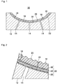
- Fig. 1 is a schematic sectional view of a mold for resin molding which is an embodiment of the present invention.
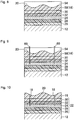
- Fig. 2 is an enlarged schematic sectional view of the mold for resin molding shown in Fig. 1 .
- Fig. 3 is an enlarged schematic sectional view showing part of the mold for resin molding shown in Fig. 1 .
- the mold for resin molding 10 includes a mold 12, which is a die intended for vacuum molding to be used when forming a resin molded product that has projections and depressions of grain pattern (such as a leather grain pattern, a texture pattern, a wood grain pattern, a satin-finished pattern, a vein pattern, a scale pattern, a marble pattern, a mirror-like pattern, a paint pattern, and a geometric pattern) on the surface.
- grain pattern such as a leather grain pattern, a texture pattern, a wood grain pattern, a satin-finished pattern, a vein pattern, a scale pattern, a marble pattern, a mirror-like pattern, a paint pattern, and a geometric pattern
- the mold 12 is made of a steel material, a low-melting metal material such as aluminum and ZAS, a synthetic resin material, wood, or the like, and has a concave mold surface.
- the mold 12 has ventilating throughholes 14 for exhausting air when pouring a melted resin into the mold-surface side during vacuum molding.
- a design layer 16 is formed on the mold surface of the mold 12.
- the design layer 16 is made of a thermosetting resin sheet, and has ventilating throughholes 18 which couple to the ventilating throughholes 14.
- a die surface 20 having fine projections and depressions is provided on the surface.
- the design layer 16 is made from a mixture of the thermosetting resin and solid particles.
- the die surface 20 has the projections and depressions of grain pattern (such as a leather grain pattern, a texture pattern, a wood grain pattern, a satin-finished pattern, a vein pattern, a scale pattern, a marble pattern, a mirror-like pattern, a paint pattern, and a geometric pattern) on the surface.
- grain pattern such as a leather grain pattern, a texture pattern, a wood grain pattern, a satin-finished pattern, a vein pattern, a scale pattern, a marble pattern, a mirror-like pattern, a paint pattern, and a geometric pattern
- a air permeable interposing layer 22 is interposed between the mold surface of the mold 12 and the design layer 16.
- the air permeable interposing layer 22 is formed by solidifying a fibrous air permeable member 24 such as paper, and has pore areas such as a gap to establish connection between the mold 12 and the design layer 16.
- the ventilating throughholes 18 are formed in the design layer 16 by running through the same with wires so as to couple to the ventilating throughholes 14 of the mold 12 when the thermosetting resin making the design layer 16 is in a softened state.
- the ventilating throughholes 14 of the mold 12 are formed to have a diameter greater than that of the ventilating throughholes 18 in the design layer 16.
- the design layer 16 is made of a thermosetting resin that has a curing temperature of 250°C or lower.
- thermosetting resins epoxy resin and other insulative thermosetting resins that cure at around 150°C and have heat insulation properties are used.
- the curing temperature of the thermosetting resin is selected depending on the allowable temperature limit heatproof temperature of the mold 12.
- a thermosetting resin that cures within the temperature range of 110°C to 150°C is used depending on the allowable temperature limit heatproof temperature of the die material.
- thermosetting resin in use shall also have a thermal conductivity of 0.18 to 0.21 W/m ⁇ K and a coefficient of thermal expansion of 3.2 to 4.6 ⁇ 10 -5 /K.
- the design layer 16 is formed so as to have a thickness of 0.1 to 0.2 mm.
- This design layer 16 is formed on both a core die and a cavity die, whereas the design layer 16 may only be formed on either one of the cavity and core dies.
- the inner surface of the mold is degreased and cleaned.
- the design layer 16 is formed by pasting a sheet of thermosetting resin such as epoxy resin or by applying the thermosetting resin so that the thermosetting resin layer is formed over the entire surface.
- the design layer 16 is made of an epoxy resin, in which ceramic whiskers having a diameter of 5.0 ⁇ 10 -5 to 1.7 ⁇ 10 -2 mm, or preferably 5.0 ⁇ 10 -4 mm, and a length of 0.01 to 0.3 mm, or preferably 0.05 mm, are mixed. While 1 to 100 parts of the whiskers are mixed into 20 parts of the epoxy resin, the amount of whiskers to be mixed in is selected appropriately depending on the amount of fillers mixed in the resin.
- the epoxy resin is a composition containing a novolac type epoxy resin and a carboxyimide anhydride complex in combination.
- the design layer 16 is made of the resin that mixes whiskers of 0.01 to 0.3 mm in length. Since the design layer 16 is made of the resin that does not contain glass fibers but fine whiskers having a diameter of 5.0 ⁇ 10 -5 to 1.7 ⁇ 10 -2 mm and a length of 0.01 to 0.3 mm, however, the whiskers can be oriented in all directions uniformly even if the design layer 16 is thin. Besides, the whiskers do not hamper the formation of the die surface having fine projections and depressions.
- the design layer 16 has a thickness of 0.12 to 0.6 mm. Its surface makes a die surface 20 having a fine concavo-convex shape which is grained by the operation of pressing a patterned die surface having the leather grain pattern of 0.001 to 0.5 mm to be formed on molded products, i.e., so called inversion operation.
- the design layer 16 may be made of such materials as epoxy resin, acrylic resin, polyacetal resin, polyamide resin, polyimide resin, polyurethane resin, polyester resin, polyethylene resin, polycarbonate resin, polypropylene resin, silicon resin, fluorine resin, melamine resin, urea resin, phenol resin, phthalic acid resin, styrene resins, cellulose resins, vinyl chloride resin, and vinyl acetate resin. These resins may be each used alone, or may be used in combination.
- epoxy resins are typically classified as thermosetting, they include ones of two-component curing type or reaction curing type, and even the epoxy resins of reaction curing type can make plastic deformation at high temperatures.
- This property can be utilized to form the design layer 16 in which a reaction-curing resin is added to a thermosetting resin as a plasticizer.
- Thermoplastic resins can also be used when molding resin molded products at temperatures below the softening point of the thermoplastic resins.
- the design layer 16 may also be made from a thermosetting resin in which a thermoplastic resin is added as a plasticizer.
- the fine concavo-convex shaped die surface 20 of the design layer 16 may be coated with a release layer containing ethylene tetrafluoride resin (typically referred to as Teflon(TM)).
- Teflon(TM) ethylene tetrafluoride resin
- This mold for resin molding 10 keeps the die temperature during vacuum molding, so that the grain (the surface concavo-convex shape) of the fine concavo-convex shaped die surface 20 can be inverted favorably.
- the forming method is the method for forming the design layer 16 by the processes in which: as shown in Figs 11A and 11B , a reverse mold 52 of silicon resin is created from a prototype 50 of leather or the like that has a leather grain pattern on the surface, and a master mold 54 of a resin for inversion is then created from the reverse mold 52 of silicon resin; (1) as shown in Fig.
- a resin sheet material 56 of whisker-containing epoxy resin is applied to and half-cured on the concavo-convex patterned surface 54a of the master mold 54 which has the concavo-convex pattern to be formed on resin molded products to thereby produce a resin sheet 58 intended for forming the design layer, having a concavo-convex shaped surface(a) to make the fine concavo-convex shaped die surface 20 on one side; (2) subsequently, the resin sheet 58 is temporarily attached to the air preamble interposing layer 22 of the mold 12; and in this state, the entire die is heated to cure the resin sheet 58.
- the techniques available for forming the resin sheet 58 include: a slip blade method; a doctor blade method; a roll method which uses a roller instead of the doctor blade in the doctor blade method; a calendar method; a paper dipping method; a continuous pressure method; an injection molding method; a slice method of slicing a resin block; a squeegee method; a stretch method of stretching semi-cured resin; a shaving method of shaving a resin block; a press molding method; a centrifugal method of stretching resin by centrifugal force; an extrusion method of extruding a sheet of resin from an extruder; and a spray method of spraying resin to a certain thickness on the die surface.
- the step (1) includes: as shown in Fig. 12A , by utilizing the flexibility of the semi-cured resin sheet material 56, pressing the resin sheet material 56 gradually from its one side against the concavo-convex patterned surface 54a of the master mold 54; or as shown in Fig. 12B , pressing the resin sheet material 56 gradually from its center against the concavo-convex patterned surface 54a of the master mold 54 to put the resin sheet material 56 on the master mold 54 so that no air is introduced between the resin sheet material 56 and the concavo-convex patterned surface 54a.
- the concavo-convex patterned die surface 20 of the resin sheet 58 may also be covered with a protective layer which is made of wax or other material that melts, burns out, or evaporates when heated to the curing temperature of the resin sheet 58.
- the design layer 16 has a fine grain pattern, by inverting from the master mold 54, and has the effect of thermal insulation which improves the grain inversion rate of this mold for resin molding 10 to molded products.
- the air permeable interposing layer 22 is formed by applying, drying, and curing dispersed pulp or other fibrous air permeable member 24 and the same resin (common material) as that of the design layer 16.
- This air permeable interposing layer also functions as an adhesive layer of 0.005 to 0.1 mm in thickness, and has pore areas all over.
- the air permeable interposing layer 22 made of the fibrous air permeable member such as pulp and rock wool is formed, for example, in the following manner.
- the common material (being the same resin as that of the design layer) is applied onto the mold 12 in a small thickness and dried to form a first air permeable adhesive layer 26. Then, the top of the first air permeable adhesive layer 26 is coated with the fibrous air permeable member 24 consisting of pulp, rock wool, or the like dispersed in water, followed by drying. Alternatively, if the air permeable member 24 is made of a packed material of fibers such as felt, the air permeable member 24 is pasted onto the first air permeable adhesive layer 26. Subsequently, the common material (being the same resin as that of the design layer) is applied to the surface of the air permeable member 24 further and dried to form the second air permeable adhesive layer, and then the design layer 16 is bonded thereto.
- the common material being the same resin as that of the design layer
- the air permeable interposing layer 22 must have holes of 0.01 mm or more and less than 0.2 mm all over, thereby making pore areas.
- Pore areas of 0.2 mm or more can be formed up to about 20% of the entire surface. If pores of 0.2 mm or more cover more than 20% of the surface, however, the design layer 16 may be recessed in the surface.
- the porosity falls within the range of 50% inclusive to 100% exclusive.
- the air permeable interposing layer 22 secures proper ventilation characteristic by having pore areas all over. Thus, if a large amount of resin is impregnated into the air permeable member 24, the air permeable member 24 clogged up with the resin might drop in porosity and fail to exercise the ventilation property.
- the first air permeable adhesive layer 26 and the second air permeable adhesive layer 30 are then made sufficiently smaller than the air permeable member 24 in thickness, so that the amount of resin impregnated into the air permeable member 24 is adjusted not to impair the ventilation property.
- the air permeable member 24 that forms the air permeable interposing layer 22 may be made of: various types of foamed materials (including such as PVA, melamine, and urethane); porous materials which are made from composite materials of resin and fine particles that disappear when heated to cure, such as sodium chloride, calcium carbonate, and sodium hydrogen carbonate; composite materials that contain resin, carbon, and sand so that the particles leave gaps therebetween; packed products of fibers such as pulp and rock wool; felt; or combinations of the these.
- foamed materials including such as PVA, melamine, and urethane
- porous materials which are made from composite materials of resin and fine particles that disappear when heated to cure, such as sodium chloride, calcium carbonate, and sodium hydrogen carbonate
- composite materials that contain resin, carbon, and sand so that the particles leave gaps therebetween packed products of fibers such as pulp and rock wool; felt; or combinations of the these.
- a diluted resin is prepared by mixing the common material of the design layer 16 (common material being the same resin as that of the design layer), such as diluted resin prepared by mixing 20% to 70% by weight of solvent (ethyl cellosolve acetate) with epoxy resin.
- the diluted resin is sprayed onto the surface of the mold 12, thereby the first air permeable adhesive layer 26 is formed.
- the common material of the first air permeable adhesive layer 26 is dried and semi-cured, thereby the first air permeable adhesive layer 26 is formed.
- a porous air permeable member 24 such as a 0.5 mm-thick sponge sheet having continuous pores is temporarily bonded on the first air permeable adhesive layer 26 with a spray glue.
- the first air permeable adhesive layer 26 is heated to around 200°C for curing.
- the dried resin of this first air permeable adhesive layer 26 once drops in viscosity before curing.
- the resin is thus impregnated into pores of the air permeable member 24 due to a capillary phenomenon, thereby forming a first air permeable impregnation layer 28.
- the resin is thermally cured, and the mold 12, the air permeable member 24, the first air permeable adhesive layer 26, and the first air permeable impregnation layer 28 are integrated.
- the air permeable member 24 is made of a ventilating material resistant to the resin of the first air permeable adhesive layer 26 and to the solvent contained in the resin.
- first air permeable adhesive layer 26 is made of epoxy resin
- ethyl cellosolve acetate is used as the diluent solvent.
- thermosetting resin is selected as the resin material used for the first air permeable adhesive layer 26, however, substances that melt at the curing temperature cannot be used.
- a diluted resin is prepared by mixing 20% to 70% by weight of solvent (ethyl cellosolve acetate) with epoxy resin, the same resin as that of the design layer 16.
- the diluted resin is sprayed onto the air permeable member 24 to form the second air permeable adhesive layer 30 on the air permeable member 24.
- some of the resin is absorbed into the air permeable member 24, thereby a second air permeable impregnation layer 32 is formed.
- the resin is dried and cured to form the second air permeable adhesive layer 30 and the second air permeable impregnation layer 32.
- the resin sheet 58 for forming the design layer 16 is pasted onto the air permeable interposing layer 22 along with the master mold 54.
- the resin sheet 58 for forming the design layer 16 is temporarily bonded on the second air permeable adhesive layer 30 with a spray glue.
- preheating is performed while needles 60 or the like are stuck into the master mold 54, the resin sheet 58 for forming the design layer 16, the second air permeable adhesive layer 30, and the second air permeable impregnation layer 32, in such a manner as to penetrate therethrough.
- the master mold 54 and the needles 60 are removed from the design layer 16, followed by full heating at temperatures higher than in the preheating.
- the second air permeable adhesive layer 30 is formed by applying the common material (being the same resin as that of the design layer) to the air permeable member 24 so that it is impregnated into the surface of the material for forming the air permeable member 24, and heating it to cure and adhere to the air permeable member 24 and the design layer 16 together. It is therefore an essential condition that the air permeable interposing layer 22 is made of a ventilating material resistant to the resin of the design layer 16 and to the solvent contained in the resin.
- the design layer is made of epoxy resin
- ethyl cellosolve acetate is used as the diluent solvent.
- a thermosetting resin is selected as the resin used for the design layer 16, however, materials that melt at the curing temperature cannot be used.
- the air permeable interposing layer 22 is composed of the air permeable member 24 that is made of fibrous material such as pulp, the first air permeable adhesive layer 26 that is formed by applying and curing the common resin material of the design layer 16, i.e. the same resin material as that of the design layer 16, formed on a side of the air permeable member 24 facing toward a side of the mold 12, the first air permeable impregnation layer 28 in which the common resin material of the design layer 16 which forms the first air permeable adhesive layer 26 is formed by impregnating with the air permeable member 24, the second air permeable adhesive layer 30 that is formed by applying and curing the common resin material of the design layer 16, i.e.
- the air permeable interposing layer 22 from a foamed air permeable member 24 it is formed by: forming a foamed sheet by means of using a foaming agent; bonding the air permeable member 24 made of the foamed sheet to the mold 12 with the same resin as that of the design layer 16; and bonding the air permeable member 24 made of the foamed sheet to the design layer 16 with the same resin as that of the design layer 16.
- the foamed material desirably has continuous pores, whereas foamed material having single pores can also be used for ventilation purpose by linking the single pores to each other.
- foamed material having single pores can also be used for ventilation purpose by linking the single pores to each other.
- the method of forming the air permeable interposing layer 22 from an air permeable member 24 of porous material for example, it is formed by: making a porous member by means of thermally fusion bonding sand particles coated with phenol or other thermosetting resin; bonding the air permeable member 24 made of the porous member to the mold 12 with the same resin as that of the design layer 16; and bonding the air permeable member 24 made of the porous member to the design layer 16 with the same resin as that of the design layer 16.
- the reason for using sand or other solids surface-coated with phenol resin is that the coating resin on the solid surfaces function as a binder so that the sand or other solids adhere to each other to form the air permeable member.
- particulates coated with resin may be used as another method of forming the air permeable interposing layer 22 from an air permeable member 24 of porous material.
- An excessive amount of particulates having random shapes may be mixed into the resin, so that the resin, when cured, has gaps even inside.
- the porosity of the air permeable member 24 shall range from 50% inclusive to 100% exclusive.
- the air permeable member 24 when using the same resin material (common material) as that of the first air permeable adhesive layer 26 and the second air permeable adhesive layer 30, is integrated with the first air permeable adhesive layer 26, the second air permeable adhesive layer 30 and the like by heating, and adhesivity is expressed. Some of the resin is absorbed into pores in the air permeable member 24 due to a capillary phenomenon, thereby providing an even higher adhesion.
- fibrous air permeable member 24 paper, fabric, felt and the like may be used aside from those mentioned above.
- the projections and depressions on the surface of the air permeable interposing layer 22 are utilized to enhance the adhesion between the air permeable interposing layer 22, the mold 12, and the design layer 16 by an anchor effect. This secures the adhesion between the air permeable interposing layer 22 and the mold 12 and the adhesion between the air permeable interposing layer 22 and the design layer 16.
- the ventilating throughholes 18 are formed in the design layer 16 by such methods as: perforating with pointed tools like piano wires or other wires; thermally melting the design layer 16 with laser for perforation; and perforating by a perforating machine.
- needles or the like may be stuck into the design layer 16 before the curing of the design layer 16, and removed from the thermally-cured design layer 16 to form the ventilating throughholes 18.
- the needles or the like can be removed or eliminated after or in the process of curing the resin so that the resin may not previously spread to the area forming the ventilating throughholes 18.
- the ventilating throughholes 18 need not be made in the same positions as those of the ventilating throughholes 14 which are formed in the mold 12 in advance, as long as they have a depth to reach the air permeable interposing layer 22.
- thermosetting resin for the design layer 16 with a curing temperature of around 150°C, may be used, so that the firing temperature can be lowered to be 200°C or less when forming the design layer 16. This reduces a difference in size to occur during firing due to a difference of the coefficient of thermal expansion between the mold 12 and the thermosetting resin, and thus suppresses the generation of cracks in the design layer 16.
- the steps of applying the thermosetting resin material in a small thickness and firing the same need not be repeated over and over, and the design layer 16 can be formed by respective single steps of pasting and curing the thermosetting resin material. This facilitates the formation of the design layer 16.
- the design layer 16 is made of the thermosetting resin having a low curing temperature, and therefore, a thick design layer 16 can be formed easily by a single step of pasting. This facilitates repairing the design layer 16 even when damaged.
- the low firing temperature of the design layer 16 during formation suppresses deformation of the mold 12, and makes it possible to obtain resin molded products of precise shape.
- the design layer 16 can also be formed on a mold 12 that is made of a material having a deforming temperature of around 300°C, such as aluminum.
- the thermosetting resin having a low curing temperature can also be used to form the design layer 16 not only on a mold 12 that is made of metal but on a mold 12 that is made of resin as well.
- the air permeable adhesive layers may be bonded in the following way.
- the bonding formation mechanism is identical both (a) when bonding the mold 12 and the air permeable interposing layer 22 and (b) when bonding the design layer 16 and the air permeable interposing layer 22.
- the bonding order may be such that (a) is cured first and (b) afterward, or (a) and (b) simultaneously.
- the bonding forces are obtained by heating and curing the thermosetting resin, for example.
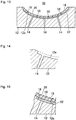
- the air permeable interposing layer 22 need not be formed over the entire mold surface of the mold 12. As shown in Figs. 13 to 15 , a recess 12a may be formed in part of the mold surface of the mold 12 by carving the thickness of the air permeable interposing layer 22 so that the air permeable interposing layer 22 is formed in the part of the mold surface of the mold 12 by forming in the recess 12a.
- the air permeable interposing layer 22 When the air permeable interposing layer 22 is formed in the recess 12a, the first air permeable adhesive layer 26 and the first air permeable impregnation layer 28 may be not formed. In this instance, the air permeable member 24 made of a ventilating material greater than the recess 12a may be pressed into and fixed to form the air permeable interposing layer 22.
- the ventilating throughholes 18 may be formed in arbitrary positions as long as they have a depth to reach the air permeable interposing layer 22. In such cases that the ventilating throughholes 18 are clogged up in the process of shape forming, perforation can thus be applied to other locations without cleaning the clogged holes.
- the ventilating throughholes 14 in the mold 12 may be formed by installing hollow pipes, and the ventilating throughholes 18 may be formed by perforating the design layer 16 with wires from the hollow pipe side.
- the ventilating throughholes 14 of the mold may be filled with sponge or other ventilating material so as to avoid clogging.
- the mold surface of a die 12 is degreased and cleaned with an organic solvent such as tetrachloroethylene, methanol, and thinner.
- Unused areas not to be processed are masked with a predetermined masking material, a sealing tape, or the like.
- a diluted resin prepared by mixing epoxy resin and 20% to 70% by weight of solvent (ethyl cellosolve acetate) is sprayed onto the mold surface of the mold 12, thereby forming a first air permeable adhesive layer 26 over the mold surface of the mold 12.
- This first air permeable adhesive layer 26 is then dried to form the first air permeable adhesive layer 26.
- epoxy resin 100 parts by weight is mixed with 50 to 98 parts by weight of random-shaped ceramic particulates having diameters of 0.01 to 0.5 mm. If the particulates are difficult to be mixed with the resin caused by high viscosity, 20 to 70 parts by weight of diluent solvent (ethyl cellosolve acetate) is added to the epoxy resin for viscosity adjustment.
- diluent solvent ethyl cellosolve acetate
- the epoxy resin that contains 20 to 70 parts by weight of diluent solvent (ethyl cellosolve acetate), mixed with 50 to 98 parts by weight of the random-shaped ceramic particulates having diameters of 0.01 to 0.5 mm, is applied onto the first air permeable adhesive layer 26 to a thickness of 0.002 to 5 mm, thereby forming an air permeable member 24.
- the first air permeable adhesive layer 26 is heated to cure at approximately 200°C.
- the resin is also impregnated into the pores in the air permeable member 24 due to a capillary phenomenon, thereby forming a first air permeable impregnation layer 28.
- the mold 12, the air permeable member 24, the first air permeable adhesive layer 26, and the first air permeable impregnation layer 28 are thermally cured for integration.
- a diluted resin prepared by mixing epoxy resin and 20% to 70% by weight of solvent (ethyl cellosolve acetate) is sprayed onto the air permeable member 24, thereby forming a second air permeable adhesive layer 30 on the air permeable member 24.
- solvent ethyl cellosolve acetate
- some of the resin is absorbed into the air permeable member 24 to form a second air permeable impregnation layer 32.
- a reverse mold 52 of silicon is created from leather being a prototype 50.
- polyurethane resin being a resin sheet material 56 is poured onto the silicon reverse mold 52, thereby creating a master mold 54.
- Epoxy resin is then applied (poured) onto the die surface of the polyurethane resin master mold 54, thereby forming a grain-patterned resin sheet 58.
- This inversion from the prototype 50 such as leather is repeated to form the grained resin sheet 58 which makes a grained design layer consisting primarily of epoxy resin.
- the resultant is then bonded to the second air permeable adhesive layer 30 along with the master mold 54.
- the grained resin sheet 58 is temporarily bonded with a spray glue. It is better for maintaining the die surface to paste the grained resin sheet 58 to the air permeable interposing layer 22 along with the master mold 54.
- preheating is performed at approximately 100°C while needles or the like are stuck into the master mold 54, the design layer 16, the second air permeable adhesive layer 30, and the second air permeable impregnation layer 32, in such a manner as to penetrate therethrough.
- the second air permeable adhesive layer 30 and the grained resin sheet 58 react to become rigid, thereby forming the design layer 16.
- the design layer 16 may be perforated with the ventilating throughholes 18 having a depth to reach the air permeable interposing layer 22 at desired positions by using a laser or by mechanical means such as a punch.
- the air permeable interposing layer has pore areas that couple to the ventilating throughholes 14 and the ventilating throughholes 18.
- the thicknesses of the respective layers are as follows.
- the thickness of the air permeable interposing layer 0.012 to 5.2 mm
- the thickness of the design layer 0.12 to 0.6 mm
- the thicknesses of the first and second air permeable adhesive layers 0.005 to 0.1 mm
- the total thickness of the foregoing three layers 0.132 to 5.8 mm
- the mold surface of a die 12 is degreased and cleaned with an organic solvent such as tetrachloroethylene, methanol, or thinner.
- Unused areas not to be processed are masked with a predetermined masking material, a sealing tape, or the like.
- An epoxy resin diluted with ethyl cellosolve acetate (diluent solvent) is applied onto the mold surface of the mold 12 to a thickness of 0.002 to 5 mm, and semi-cured to form a first air permeable adhesive layer 26.
- an air permeable member 24 made of pulp dispersed in water is applied to a thickness of 0.002 to 5 mm and dried to form a ventilating material layer.
- the epoxy resin diluted by ethyl cellosolve acetate (diluent solvent) is applied onto the surface to form the design layer 16 to a thickness of 0.005 to 0.1 mm, thereby forming a second air permeable adhesive layer 30.
- a reverse mold 52 of silicon is created from leather being a prototype 50.
- polyurethane resin being a resin sheet material 56 is poured onto the silicon reverse mold 52, thereby creating a master mold 54.
- Epoxy resin is then applied (poured) onto the die surface of the polyurethane resin master mold 54, thereby forming a grain-patterned resin sheet 58.
- This inversion from the prototype 50 such as leather is repeated to form the grained resin sheet 58 which makes a grained design layer 16 consisting primarily of epoxy resin.
- the resultant is then bonded to the second air permeable adhesive layer 30 along with the master mold 54.
- the grained resin sheet 58 is temporarily bonded with a spray glue. It is better for maintaining the die surface to paste the grained resin sheet 58 to the air permeable interposing layer 22 along with the master mold 54.
- preheating is performed at approximately 100°C while needles or the like are stuck into the master mold 54, the design layer 16, the second air permeable adhesive layer 30, and the second air permeable impregnation layer 32, in such a manner as to penetrate therethrough.
- the second air permeable adhesive layer 30 and the grained resin sheet 58 react to become rigid, thereby forming the design layer 16.
- the design layer 16 may be perforated with the ventilating throughholes 18 having a depth to reach the air permeable interposing layer 22 at desired positions by using a laser or by mechanical means such as a punch.
- the air permeable interposing layer has pore areas that couple to the ventilating throughholes 14 and the ventilating throughholes 18.
- the thicknesses of the respective layers are as follows.
- the thickness of the air permeable interposing layer 0.012 to 5.2 mm
- the thickness of the design layer 0.12 to 0.6 mm
- the thicknesses of the first and second air permeable adhesive layers 0.005 to 0.1 mm
- the total thickness of the foregoing three layers 0.132 to 5.8 mm
- the mold surface of a die 12 is degreased and cleaned with an organic solvent such as tetrachloroethylene, methanol, or thinner.
- Unused areas not to be processed are masked with a predetermined masking material, a sealing tape, or the like.
- thermosetting silicon resin is applied or sprayed to form a second air permeable adhesive layer 30.
- a grained resin sheet 58 consisting primarily of the thermosetting silicon resin is bonded thereto.
- the second air permeable adhesive layer 30 for bonding has flowability and thus adheres because of surface tension.
- the grained resin sheet 58 is molded as in the embodiment 1.
- the semi-cured-state thermosetting silicon resin for making the second air permeable adhesive layer 30 is fully heated at approximately 150°C, and dried.
- the second air permeable adhesive layer 30 and the grained resin sheet 58 react to cure, thereby forming the design layer 16.
- the design layer 16 may be perforated with the ventilating throughholes having a depth to reach the air permeable interposing layer at desired positions by using a laser or by mechanical means such as a punch.
- the air permeable interposing layer has pore areas that couple to the ventilating throughholes 14 and the ventilating throughholes 18.
- the thicknesses of the respective layers are as follows.
- the thickness of the air permeable interposing layer 0.012 to 5.2 mm
- the thickness of the design layer 0.12 to 0.6 mm
- the thicknesses of the first and second air permeable adhesive layers 0.005 to 0.1 mm
- the total thickness of the foregoing three layers 0.132 to 5.8 mm
- the mold surface of a die 12 is degreased and cleaned with an organic solvent such as tetrachloroethylene, methanol, and thinner.
- Unused areas not to be processed are masked with a predetermined masking material, a sealing tape, or the like.
- the grained resin sheet 58 is molded as in the embodiment 1.
- the design layer 16 may be perforated with the ventilating throughholes having a depth to reach the air permeable interposing layer at desired positions by using a laser or by mechanical means such as a punch.
- the air permeable interposing layer has pore areas that couple to the ventilating throughholes 14 and the ventilating throughholes 18.
- the thicknesses of the respective layers are as follows.
- the thickness of the air permeable interposing layer 0.012 to 5.2 mm
- the thickness of the design layer 0.12 to 0.6 mm
- the thicknesses of the first and second air permeable adhesive layers 0.005 to 0.1
- the total thickness of the foregoing three layers 0.132 to 5.8 mm
- the mold surface of a die 12 is degreased and cleaned with an organic solvent such as tetrachloroethylene, methanol, and thinner.
- Unused areas not to be processed are masked with a predetermined masking material, a sealing tape, or the like.
- the grained resin sheet 58 is molded as in the embodiment 1.
- the design layer 16 may be perforated with the ventilating throughholes having a depth to reach the air permeable interposing layer at desired positions by using a laser or by mechanical means such as a punch.
- the air permeable interposing layer has pore areas that couple to the ventilating throughholes 14 and the ventilating throughholes 18.
- the thicknesses of the respective layers are as follows.
- the thickness of the air permeable interposing layer 0.012 to 5.2 mm
- the thickness of the design layer 0.12 to 0.6 mm
- the thicknesses of the first and second air permeable adhesive layers 0.005 to 0.1 mm
- the total thickness of the foregoing three layers 0.132 to 5.8 mm
- a melted resin such as polypropylene is poured or a thermally-softened sheet material of polyurethane or the like is placed into the mold for resin molding.
- the mold for resin molding is then exhausted through the ventilating throughholes 14 so that the melted resin is sucked to the surface of the design layer for molding, thereby forming a resin molded product.
Landscapes
- Engineering & Computer Science (AREA)
- Mechanical Engineering (AREA)
- Manufacturing & Machinery (AREA)
- Moulds For Moulding Plastics Or The Like (AREA)
- Casting Or Compression Moulding Of Plastics Or The Like (AREA)
- Laminated Bodies (AREA)
Description
- The present invention relates to a mold for resin molding and a method for manufacturing a mold for resin molding. In particular, the present invention relates to a mold for resin molding intended for resin molding by vacuum molding to be used when forming a resin molded product that has projections and depressions of grain pattern (such as a leather grain pattern, a texture pattern, a wood grain pattern, a satin-finished pattern, a vein pattern, a scale pattern, a marble pattern, a mirror-like pattern, a paint pattern, and a geometric pattern) on the surface, and a method for manufacturing the same.
- Among molds for resin molding intended for resin molding, there have been suggested dies forming a resin layer.
- One example is a mold for resin molding on which a special thermosetting resin layer of grain pattern is formed. This die is fabricated by inverting desired grain from a master, and thus has grain of high precision as compared to etching techniques. This die also provides the effect of thermal insulation which contributes to an improvement in the grain inversion rate during molding and a reduction of weld lines (see Patent Document 1).
- [PATENT DOCUMENT 1] Japanese Examined Patent Application Publication No. Heisei
-
US 4 872 827 A discloses a porous die including a porous die body with a plurality of pores formed therein, a cooling chamber provided in direct contact with the back side of the porous die body in order to cool the porous die body, a device for supplying a coolant to the cooling chamber, and suction holes through which the cooling chamber is evacuated and the air and the coolant entering the cooling chamber are simultaneously sucked. The cooling chamber is densely filled with stainless steel fibrous bodies. -
JP 8 150624 A - The die described in Patent Document 1 itself cannot be used for vacuum molding since vacuum dies must have exhaust holes while the grained resin layer formed over the die can block exhaust holes.
- Then, in order to secure exhaust holes formed in the die, it is conceivable that the grained resin layer, after formed on the die, could be subjected to the operation of perforation by using wires inserted through the exhaust holes from the back of the die so that holes are made in the same positions as the exhaust holes. Vacuum molding dies have a large number of exhaust holes, however. For example, typical dies of automotive parts have more than 100 exhaust holes. It thus requires an enormous amount of work to apply the foregoing operation to all the exhaust holes.
- In addition, the exhaust holes may cause a problem of clogging during vacuum molding, in which case the holes must be cleaned with an enormous amount of work again.
- In view of the foregoing, a main object of the present invention is to provide a mold for resin molding which ensures ventilation characteristic without requiring an enormous amount of work, a method for manufacturing the mold for resin molding, and a resin molded product that is molded by using the same.
- The invention provides a mold for resin molding according to claim 1 and a method according to claim 5.
- Further developments of the invention are defined in the dependent claims.
- The provision of the air permeable interposing layer eliminates the need to make holes in the same positions as those of the ventilating throughholes previously formed in the die, i.e., those of the exhaust holes. The operation of making the ventilating throughholes, i.e., the holes intended for exhausting can thus be performed relatively easily.
- After the formation of the design layer, ventilating throughholes may be perforated in any positions as long as the holes have a depth to reach the air permeable interposing layer. Even if the ventilating throughholes are clogged up during molding, other locations can be readily perforated without hole cleaning.
- The foregoing and other objects, features, and advantages of the present invention will become more apparent from the following description of the preferred embodiment of the invention when read in conjunction with the drawings.
-
- [
Fig. 1] Fig. 1 is a schematic sectional view of a mold for resin molding which is an embodiment of the present invention; - [
Fig. 2] Fig. 2 is an enlarged schematic sectional view of the mold for resin molding shown inFig. 1 ; - [
Fig. 3] Fig. 3 is an enlarged schematic sectional view showing part of the mold for resin molding shown inFig. 1 ; - [
Fig. 4] Fig. 4 is a schematic sectional view showing a method for manufacturing the mold for resin molding shown inFig. 1 ; - [
Fig. 5] Fig. 5 is a schematic sectional view showing the method for manufacturing the mold for resin molding shown inFig. 1 ; - [
Fig. 6] Fig. 6 is a schematic sectional view showing the method for manufacturing the mold for resin molding shown inFig. 1 ; - [
Fig. 7] Fig. 7 is a schematic sectional view showing the method for manufacturing the mold for resin molding shown inFig. 1 ; - [
Fig. 8] Fig. 8 is a schematic sectional view showing the method for manufacturing the mold for resin molding shown inFig. 1 ; - [
Fig. 9] Fig. 9 is a schematic sectional view showing the method for manufacturing the mold for resin molding shown inFig. 1 ; - [
Fig. 10] Fig. 10 is a schematic sectional view showing the method for manufacturing the mold for resin molding shown inFig. 1 ; - [
Fig. 11] Figs. 11A to 11C are schematic sectional views showing a method for manufacturing a resin sheet of the mold for resin molding shown inFig. 1 ; - [
Fig. 12] Figs. 12A and 12B are schematic sectional views showing another method for manufacturing the resin sheet of the mold for resin molding shown inFig. 1 ; - [
Fig. 13] Fig. 13 is a schematic sectional view showing a mold for resin molding which is a modification of the mold for resin molding shown inFig. 1 ; - [
Fig. 14] Fig. 14 is an enlarged schematic sectional view of the mold for resin molding shown inFig. 13 ; and - [
Fig. 15] Fig. 15 is an enlarged schematic sectional view of the mold for resin molding shown inFig. 13 . -
- 10
- mold for resin molding
- 12
- mold
- 14
- ventilating throughhole
- 16
- design layer
- 18
- ventilating throughhole
- 20
- die surface
- 22
- air permeable interposing layer
- 24
- air permeable member
- 26
- first air permeable adhesive layer
- 28
- first air permeable impregnation layer
- 30
- second air permeable adhesive layer
- 32
- second air permeable impregnation layer
- 50
- prototype
- 52
- reverse mold
- 54
- master mold
- 56
- resin sheet material
- 58
- resin sheet
- 60
- needle
-
Fig. 1 is a schematic sectional view of a mold for resin molding which is an embodiment of the present invention.Fig. 2 is an enlarged schematic sectional view of the mold for resin molding shown inFig. 1 .Fig. 3 is an enlarged schematic sectional view showing part of the mold for resin molding shown inFig. 1 . - The mold for
resin molding 10 includes amold 12, which is a die intended for vacuum molding to be used when forming a resin molded product that has projections and depressions of grain pattern (such as a leather grain pattern, a texture pattern, a wood grain pattern, a satin-finished pattern, a vein pattern, a scale pattern, a marble pattern, a mirror-like pattern, a paint pattern, and a geometric pattern) on the surface. For example, themold 12 is made of a steel material, a low-melting metal material such as aluminum and ZAS, a synthetic resin material, wood, or the like, and has a concave mold surface. - The
mold 12 has ventilating throughholes 14 for exhausting air when pouring a melted resin into the mold-surface side during vacuum molding. - A
design layer 16 is formed on the mold surface of themold 12. Thedesign layer 16 is made of a thermosetting resin sheet, and has ventilating throughholes 18 which couple to theventilating throughholes 14. Adie surface 20 having fine projections and depressions is provided on the surface. Thedesign layer 16 is made from a mixture of the thermosetting resin and solid particles. Thedie surface 20 has the projections and depressions of grain pattern (such as a leather grain pattern, a texture pattern, a wood grain pattern, a satin-finished pattern, a vein pattern, a scale pattern, a marble pattern, a mirror-like pattern, a paint pattern, and a geometric pattern) on the surface. - A air
permeable interposing layer 22 is interposed between the mold surface of themold 12 and thedesign layer 16. The airpermeable interposing layer 22 is formed by solidifying a fibrous airpermeable member 24 such as paper, and has pore areas such as a gap to establish connection between themold 12 and thedesign layer 16. - The ventilating throughholes 18 are formed in the
design layer 16 by running through the same with wires so as to couple to the ventilating throughholes 14 of themold 12 when the thermosetting resin making thedesign layer 16 is in a softened state. - The ventilating throughholes 14 of the
mold 12 are formed to have a diameter greater than that of the ventilating throughholes 18 in thedesign layer 16. - The
design layer 16 is made of a thermosetting resin that has a curing temperature of 250°C or lower. Among examples of such thermosetting resins, epoxy resin and other insulative thermosetting resins that cure at around 150°C and have heat insulation properties are used. It should be noted that the curing temperature of the thermosetting resin is selected depending on the allowable temperature limit heatproof temperature of themold 12. For example, when thedesign layer 16 is formed on amold 12 that is made of a low-melting material such as aluminum and ZAS, a thermosetting resin that cures within the temperature range of 110°C to 150°C is used depending on the allowable temperature limit heatproof temperature of the die material. This thermosetting resin in use shall also have a thermal conductivity of 0.18 to 0.21 W/m·K and a coefficient of thermal expansion of 3.2 to 4.6 × 10⁻⁵ /K. Thedesign layer 16 is formed so as to have a thickness of 0.1 to 0.2 mm. - This
design layer 16 is formed on both a core die and a cavity die, whereas thedesign layer 16 may only be formed on either one of the cavity and core dies. - To form such a
design layer 16, the inner surface of the mold is degreased and cleaned. - The
design layer 16 is formed by pasting a sheet of thermosetting resin such as epoxy resin or by applying the thermosetting resin so that the thermosetting resin layer is formed over the entire surface. - The
design layer 16 is made of an epoxy resin, in which ceramic whiskers having a diameter of 5.0 × 10⁻⁵ to 1.7 × 10⁻² mm, or preferably 5.0 × 10⁻⁴ mm, and a length of 0.01 to 0.3 mm, or preferably 0.05 mm, are mixed. While 1 to 100 parts of the whiskers are mixed into 20 parts of the epoxy resin, the amount of whiskers to be mixed in is selected appropriately depending on the amount of fillers mixed in the resin. The epoxy resin is a composition containing a novolac type epoxy resin and a carboxyimide anhydride complex in combination. - The
design layer 16 is made of the resin that mixes whiskers of 0.01 to 0.3 mm in length. Since thedesign layer 16 is made of the resin that does not contain glass fibers but fine whiskers having a diameter of 5.0 × 10⁻⁵ to 1.7 × 10⁻² mm and a length of 0.01 to 0.3 mm, however, the whiskers can be oriented in all directions uniformly even if thedesign layer 16 is thin. Besides, the whiskers do not hamper the formation of the die surface having fine projections and depressions. - The
design layer 16 has a thickness of 0.12 to 0.6 mm. Its surface makes adie surface 20 having a fine concavo-convex shape which is grained by the operation of pressing a patterned die surface having the leather grain pattern of 0.001 to 0.5 mm to be formed on molded products, i.e., so called inversion operation. - Aside from the foregoing, the
design layer 16 may be made of such materials as epoxy resin, acrylic resin, polyacetal resin, polyamide resin, polyimide resin, polyurethane resin, polyester resin, polyethylene resin, polycarbonate resin, polypropylene resin, silicon resin, fluorine resin, melamine resin, urea resin, phenol resin, phthalic acid resin, styrene resins, cellulose resins, vinyl chloride resin, and vinyl acetate resin. These resins may be each used alone, or may be used in combination. - While epoxy resins are typically classified as thermosetting, they include ones of two-component curing type or reaction curing type, and even the epoxy resins of reaction curing type can make plastic deformation at high temperatures. This property can be utilized to form the
design layer 16 in which a reaction-curing resin is added to a thermosetting resin as a plasticizer. Thermoplastic resins can also be used when molding resin molded products at temperatures below the softening point of the thermoplastic resins. Moreover, thedesign layer 16 may also be made from a thermosetting resin in which a thermoplastic resin is added as a plasticizer. - The fine concavo-convex shaped
die surface 20 of thedesign layer 16 may be coated with a release layer containing ethylene tetrafluoride resin (typically referred to as Teflon(TM)). - This mold for
resin molding 10 keeps the die temperature during vacuum molding, so that the grain (the surface concavo-convex shape) of the fine concavo-convex shapeddie surface 20 can be inverted favorably. - Next, the method for forming the
design layer 16, or the method for forming the fine concavo-convex shapeddie surface 20 in particular, will be described mainly with reference toFig. 11 . - The forming method is the method for forming the
design layer 16 by the processes in which: as shown inFigs 11A and 11B , areverse mold 52 of silicon resin is created from aprototype 50 of leather or the like that has a leather grain pattern on the surface, and amaster mold 54 of a resin for inversion is then created from thereverse mold 52 of silicon resin; (1) as shown inFig. 11C , aresin sheet material 56 of whisker-containing epoxy resin is applied to and half-cured on the concavo-convexpatterned surface 54a of themaster mold 54 which has the concavo-convex pattern to be formed on resin molded products to thereby produce aresin sheet 58 intended for forming the design layer, having a concavo-convex shaped surface(a) to make the fine concavo-convex shapeddie surface 20 on one side; (2) subsequently, theresin sheet 58 is temporarily attached to the airpreamble interposing layer 22 of themold 12; and in this state, the entire die is heated to cure theresin sheet 58. - The techniques available for forming the
resin sheet 58 include: a slip blade method; a doctor blade method; a roll method which uses a roller instead of the doctor blade in the doctor blade method; a calendar method; a paper dipping method; a continuous pressure method; an injection molding method; a slice method of slicing a resin block; a squeegee method; a stretch method of stretching semi-cured resin; a shaving method of shaving a resin block; a press molding method; a centrifugal method of stretching resin by centrifugal force; an extrusion method of extruding a sheet of resin from an extruder; and a spray method of spraying resin to a certain thickness on the die surface. - The step (1) includes: as shown in
Fig. 12A , by utilizing the flexibility of the semi-curedresin sheet material 56, pressing theresin sheet material 56 gradually from its one side against the concavo-convexpatterned surface 54a of themaster mold 54; or as shown inFig. 12B , pressing theresin sheet material 56 gradually from its center against the concavo-convexpatterned surface 54a of themaster mold 54 to put theresin sheet material 56 on themaster mold 54 so that no air is introduced between theresin sheet material 56 and the concavo-convexpatterned surface 54a. - In addition, in the step (2), the concavo-convex
patterned die surface 20 of theresin sheet 58 may also be covered with a protective layer which is made of wax or other material that melts, burns out, or evaporates when heated to the curing temperature of theresin sheet 58. - The
design layer 16 has a fine grain pattern, by inverting from themaster mold 54, and has the effect of thermal insulation which improves the grain inversion rate of this mold forresin molding 10 to molded products. - The air
permeable interposing layer 22 is formed by applying, drying, and curing dispersed pulp or other fibrous airpermeable member 24 and the same resin (common material) as that of thedesign layer 16. This air permeable interposing layer also functions as an adhesive layer of 0.005 to 0.1 mm in thickness, and has pore areas all over. - The air
permeable interposing layer 22 made of the fibrous air permeable member such as pulp and rock wool is formed, for example, in the following manner. - The common material (being the same resin as that of the design layer) is applied onto the
mold 12 in a small thickness and dried to form a first air permeableadhesive layer 26. Then, the top of the first air permeableadhesive layer 26 is coated with the fibrous airpermeable member 24 consisting of pulp, rock wool, or the like dispersed in water, followed by drying. Alternatively, if the airpermeable member 24 is made of a packed material of fibers such as felt, the airpermeable member 24 is pasted onto the first air permeableadhesive layer 26. Subsequently, the common material (being the same resin as that of the design layer) is applied to the surface of the airpermeable member 24 further and dried to form the second air permeable adhesive layer, and then thedesign layer 16 is bonded thereto. - The air
permeable interposing layer 22 must have holes of 0.01 mm or more and less than 0.2 mm all over, thereby making pore areas. - Pore areas of 0.2 mm or more can be formed up to about 20% of the entire surface. If pores of 0.2 mm or more cover more than 20% of the surface, however, the
design layer 16 may be recessed in the surface. - The porosity falls within the range of 50% inclusive to 100% exclusive.
- The air
permeable interposing layer 22 secures proper ventilation characteristic by having pore areas all over. Thus, if a large amount of resin is impregnated into the airpermeable member 24, the airpermeable member 24 clogged up with the resin might drop in porosity and fail to exercise the ventilation property. The first air permeableadhesive layer 26 and the second air permeableadhesive layer 30 are then made sufficiently smaller than the airpermeable member 24 in thickness, so that the amount of resin impregnated into the airpermeable member 24 is adjusted not to impair the ventilation property. - The air
permeable member 24 that forms the airpermeable interposing layer 22 may be made of: various types of foamed materials (including such as PVA, melamine, and urethane); porous materials which are made from composite materials of resin and fine particles that disappear when heated to cure, such as sodium chloride, calcium carbonate, and sodium hydrogen carbonate; composite materials that contain resin, carbon, and sand so that the particles leave gaps therebetween; packed products of fibers such as pulp and rock wool; felt; or combinations of the these. - Now, the adhesion between the air
permeable interposing layer 22 and themold 12 will be described mainly with reference toFigs. 4 to 6 . - Initially, a diluted resin is prepared by mixing the common material of the design layer 16 (common material being the same resin as that of the design layer), such as diluted resin prepared by mixing 20% to 70% by weight of solvent (ethyl cellosolve acetate) with epoxy resin. The diluted resin is sprayed onto the surface of the
mold 12, thereby the first air permeableadhesive layer 26 is formed. - Next, the common material of the first air permeable
adhesive layer 26 is dried and semi-cured, thereby the first air permeableadhesive layer 26 is formed. - Next, a porous air
permeable member 24 such as a 0.5 mm-thick sponge sheet having continuous pores is temporarily bonded on the first air permeableadhesive layer 26 with a spray glue. The first air permeableadhesive layer 26 is heated to around 200°C for curing. When heated, the dried resin of this first air permeableadhesive layer 26 once drops in viscosity before curing. The resin is thus impregnated into pores of the airpermeable member 24 due to a capillary phenomenon, thereby forming a first airpermeable impregnation layer 28. Subsequently, the resin is thermally cured, and themold 12, the airpermeable member 24, the first air permeableadhesive layer 26, and the first airpermeable impregnation layer 28 are integrated. - It is therefore an essential condition that the air
permeable member 24 is made of a ventilating material resistant to the resin of the first air permeableadhesive layer 26 and to the solvent contained in the resin. - For example, when the first air permeable
adhesive layer 26 is made of epoxy resin, ethyl cellosolve acetate is used as the diluent solvent. If a thermosetting resin is selected as the resin material used for the first air permeableadhesive layer 26, however, substances that melt at the curing temperature cannot be used. - The adhesion between the air
permeable interposing layer 22 and thedesign layer 16 will now be described mainly with reference toFigs. 7 to 9 . - A diluted resin is prepared by mixing 20% to 70% by weight of solvent (ethyl cellosolve acetate) with epoxy resin, the same resin as that of the
design layer 16. The diluted resin is sprayed onto the airpermeable member 24 to form the second air permeableadhesive layer 30 on the airpermeable member 24. Here, some of the resin is absorbed into the airpermeable member 24, thereby a second airpermeable impregnation layer 32 is formed. Subsequently, the resin is dried and cured to form the second air permeableadhesive layer 30 and the second airpermeable impregnation layer 32. - Next, the
resin sheet 58 for forming thedesign layer 16 is pasted onto the airpermeable interposing layer 22 along with themaster mold 54. Here, theresin sheet 58 for forming thedesign layer 16 is temporarily bonded on the second air permeableadhesive layer 30 with a spray glue. - For the purpose of securing the ventilating
throughholes 18, preheating is performed whileneedles 60 or the like are stuck into themaster mold 54, theresin sheet 58 for forming thedesign layer 16, the second air permeableadhesive layer 30, and the second airpermeable impregnation layer 32, in such a manner as to penetrate therethrough. - Then, the
master mold 54 and theneedles 60 are removed from thedesign layer 16, followed by full heating at temperatures higher than in the preheating. - The second air permeable
adhesive layer 30 is formed by applying the common material (being the same resin as that of the design layer) to the airpermeable member 24 so that it is impregnated into the surface of the material for forming the airpermeable member 24, and heating it to cure and adhere to the airpermeable member 24 and thedesign layer 16 together. It is therefore an essential condition that the airpermeable interposing layer 22 is made of a ventilating material resistant to the resin of thedesign layer 16 and to the solvent contained in the resin. - For example, when the design layer is made of epoxy resin, ethyl cellosolve acetate is used as the diluent solvent. If a thermosetting resin is selected as the resin used for the
design layer 16, however, materials that melt at the curing temperature cannot be used. - The air
permeable interposing layer 22 is composed of the airpermeable member 24 that is made of fibrous material such as pulp, the first air permeableadhesive layer 26 that is formed by applying and curing the common resin material of thedesign layer 16, i.e. the same resin material as that of thedesign layer 16, formed on a side of the airpermeable member 24 facing toward a side of themold 12, the first airpermeable impregnation layer 28 in which the common resin material of thedesign layer 16 which forms the first air permeableadhesive layer 26 is formed by impregnating with the airpermeable member 24, the second air permeableadhesive layer 30 that is formed by applying and curing the common resin material of thedesign layer 16, i.e. the same resin material as that of thedesign layer 16, formed on a side of the airpermeable member 24 facing toward thedesign layer 16, and the second airpermeable impregnation layer 32 in which the common resin material of thedesign layer 16 which makes the second air permeableadhesive layer 30 is formed by being impregnated with the airpermeable member 24. - For the method of forming the air
permeable interposing layer 22 from a foamed airpermeable member 24, it is formed by: forming a foamed sheet by means of using a foaming agent; bonding the airpermeable member 24 made of the foamed sheet to themold 12 with the same resin as that of thedesign layer 16; and bonding the airpermeable member 24 made of the foamed sheet to thedesign layer 16 with the same resin as that of thedesign layer 16. - The foamed material desirably has continuous pores, whereas foamed material having single pores can also be used for ventilation purpose by linking the single pores to each other. In addition, it is possible to make a crack to the pore walls for ventilation by applying external force to the foamed material having single pores.
- For the method of forming the air
permeable interposing layer 22 from an airpermeable member 24 of porous material, for example, it is formed by: making a porous member by means of thermally fusion bonding sand particles coated with phenol or other thermosetting resin; bonding the airpermeable member 24 made of the porous member to themold 12 with the same resin as that of thedesign layer 16; and bonding the airpermeable member 24 made of the porous member to thedesign layer 16 with the same resin as that of thedesign layer 16. - The reason for using sand or other solids surface-coated with phenol resin is that the coating resin on the solid surfaces function as a binder so that the sand or other solids adhere to each other to form the air permeable member.
- As another method of forming the air
permeable interposing layer 22 from an airpermeable member 24 of porous material, for example, particulates coated with resin may be used. An excessive amount of particulates having random shapes may be mixed into the resin, so that the resin, when cured, has gaps even inside. The porosity of the airpermeable member 24 shall range from 50% inclusive to 100% exclusive. - The air
permeable member 24, when using the same resin material (common material) as that of the first air permeableadhesive layer 26 and the second air permeableadhesive layer 30, is integrated with the first air permeableadhesive layer 26, the second air permeableadhesive layer 30 and the like by heating, and adhesivity is expressed. Some of the resin is absorbed into pores in the airpermeable member 24 due to a capillary phenomenon, thereby providing an even higher adhesion. - For the fibrous air
permeable member 24, paper, fabric, felt and the like may be used aside from those mentioned above. - As above, the projections and depressions on the surface of the air
permeable interposing layer 22 are utilized to enhance the adhesion between the airpermeable interposing layer 22, themold 12, and thedesign layer 16 by an anchor effect. This secures the adhesion between the airpermeable interposing layer 22 and themold 12 and the adhesion between the airpermeable interposing layer 22 and thedesign layer 16. - After the process of forming layer, the ventilating
throughholes 18 are formed in thedesign layer 16 by such methods as: perforating with pointed tools like piano wires or other wires; thermally melting thedesign layer 16 with laser for perforation; and perforating by a perforating machine. - Furthermore, needles or the like may be stuck into the
design layer 16 before the curing of thedesign layer 16, and removed from the thermally-cureddesign layer 16 to form theventilating throughholes 18. For that purpose, the needles or the like can be removed or eliminated after or in the process of curing the resin so that the resin may not previously spread to the area forming the ventilatingthroughholes 18. - The ventilating throughholes 18 need not be made in the same positions as those of the ventilating throughholes 14 which are formed in the
mold 12 in advance, as long as they have a depth to reach the airpermeable interposing layer 22. - To obtain such a mold for
resin molding 10, a thermosetting resin for thedesign layer 16, with a curing temperature of around 150°C, may be used, so that the firing temperature can be lowered to be 200°C or less when forming thedesign layer 16. This reduces a difference in size to occur during firing due to a difference of the coefficient of thermal expansion between themold 12 and the thermosetting resin, and thus suppresses the generation of cracks in thedesign layer 16. As a result, the steps of applying the thermosetting resin material in a small thickness and firing the same need not be repeated over and over, and thedesign layer 16 can be formed by respective single steps of pasting and curing the thermosetting resin material. This facilitates the formation of thedesign layer 16. - The
design layer 16 is made of the thermosetting resin having a low curing temperature, and therefore, athick design layer 16 can be formed easily by a single step of pasting. This facilitates repairing thedesign layer 16 even when damaged. The low firing temperature of thedesign layer 16 during formation suppresses deformation of themold 12, and makes it possible to obtain resin molded products of precise shape. Moreover, thedesign layer 16 can also be formed on amold 12 that is made of a material having a deforming temperature of around 300°C, such as aluminum. The thermosetting resin having a low curing temperature can also be used to form thedesign layer 16 not only on amold 12 that is made of metal but on amold 12 that is made of resin as well. - The air permeable adhesive layers may be bonded in the following way.
- The bonding formation mechanism is identical both (a) when bonding the
mold 12 and the airpermeable interposing layer 22 and (b) when bonding thedesign layer 16 and the airpermeable interposing layer 22. Thus, the bonding order may be such that (a) is cured first and (b) afterward, or (a) and (b) simultaneously. - The bonding forces are obtained by heating and curing the thermosetting resin, for example.
- The air
permeable interposing layer 22 need not be formed over the entire mold surface of themold 12. As shown inFigs. 13 to 15 , arecess 12a may be formed in part of the mold surface of themold 12 by carving the thickness of the airpermeable interposing layer 22 so that the airpermeable interposing layer 22 is formed in the part of the mold surface of themold 12 by forming in therecess 12a. - When the air
permeable interposing layer 22 is formed in therecess 12a, the first air permeableadhesive layer 26 and the first airpermeable impregnation layer 28 may be not formed. In this instance, the airpermeable member 24 made of a ventilating material greater than therecess 12a may be pressed into and fixed to form the airpermeable interposing layer 22. - After the formation of the
design layer 16, the ventilatingthroughholes 18 may be formed in arbitrary positions as long as they have a depth to reach the airpermeable interposing layer 22. In such cases that the ventilatingthroughholes 18 are clogged up in the process of shape forming, perforation can thus be applied to other locations without cleaning the clogged holes. - The ventilating throughholes 14 in the
mold 12 may be formed by installing hollow pipes, and the ventilatingthroughholes 18 may be formed by perforating thedesign layer 16 with wires from the hollow pipe side. - The ventilating throughholes 14 of the mold may be filled with sponge or other ventilating material so as to avoid clogging.
- The mold surface of a die 12 is degreased and cleaned with an organic solvent such as tetrachloroethylene, methanol, and thinner.
- Unused areas not to be processed are masked with a predetermined masking material, a sealing tape, or the like.
- A diluted resin prepared by mixing epoxy resin and 20% to 70% by weight of solvent (ethyl cellosolve acetate) is sprayed onto the mold surface of the
mold 12, thereby forming a first air permeableadhesive layer 26 over the mold surface of themold 12. - This first air permeable
adhesive layer 26 is then dried to form the first air permeableadhesive layer 26. - Next, for example, 100 parts by weight of epoxy resin is mixed with 50 to 98 parts by weight of random-shaped ceramic particulates having diameters of 0.01 to 0.5 mm. If the particulates are difficult to be mixed with the resin caused by high viscosity, 20 to 70 parts by weight of diluent solvent (ethyl cellosolve acetate) is added to the epoxy resin for viscosity adjustment.
- Next, 100 parts by weight of the epoxy resin that contains 20 to 70 parts by weight of diluent solvent (ethyl cellosolve acetate), mixed with 50 to 98 parts by weight of the random-shaped ceramic particulates having diameters of 0.01 to 0.5 mm, is applied onto the first air permeable
adhesive layer 26 to a thickness of 0.002 to 5 mm, thereby forming an airpermeable member 24. The first air permeableadhesive layer 26 is heated to cure at approximately 200°C. The dried resin of this first air permeableadhesive layer 26, when heated, once drops in viscosity before curing. Thus, the resin is also impregnated into the pores in the airpermeable member 24 due to a capillary phenomenon, thereby forming a first airpermeable impregnation layer 28. Subsequently, themold 12, the airpermeable member 24, the first air permeableadhesive layer 26, and the first airpermeable impregnation layer 28 are thermally cured for integration. - A diluted resin prepared by mixing epoxy resin and 20% to 70% by weight of solvent (ethyl cellosolve acetate) is sprayed onto the air
permeable member 24, thereby forming a second air permeableadhesive layer 30 on the airpermeable member 24. Here, some of the resin is absorbed into the airpermeable member 24 to form a second airpermeable impregnation layer 32. - Initially, a
reverse mold 52 of silicon is created from leather being aprototype 50. - Next, polyurethane resin being a
resin sheet material 56 is poured onto thesilicon reverse mold 52, thereby creating amaster mold 54. - Epoxy resin is then applied (poured) onto the die surface of the polyurethane
resin master mold 54, thereby forming a grain-patternedresin sheet 58. - This inversion from the
prototype 50 such as leather is repeated to form the grainedresin sheet 58 which makes a grained design layer consisting primarily of epoxy resin. The resultant is then bonded to the second air permeableadhesive layer 30 along with themaster mold 54. Here, thegrained resin sheet 58 is temporarily bonded with a spray glue. It is better for maintaining the die surface to paste the grainedresin sheet 58 to the airpermeable interposing layer 22 along with themaster mold 54. - For the purpose of securing the ventilating
throughholes 18, preheating is performed at approximately 100°C while needles or the like are stuck into themaster mold 54, thedesign layer 16, the second air permeableadhesive layer 30, and the second airpermeable impregnation layer 32, in such a manner as to penetrate therethrough. - Next, the
master mold 54 and theneedles 60 are removed. The semi-cured-state epoxy resin for making the second air permeableadhesive layer 30, diluted with ethyl cellosolve acetate (diluent solvent), is fully heated at approximately 200°C, and dried. The second air permeableadhesive layer 30 and thegrained resin sheet 58 react to become rigid, thereby forming thedesign layer 16. - Aside from the foregoing method of perforating the
design layer 16 with needles or the like for perforation, thedesign layer 16 may be perforated with the ventilatingthroughholes 18 having a depth to reach the airpermeable interposing layer 22 at desired positions by using a laser or by mechanical means such as a punch. - The air permeable interposing layer has pore areas that couple to the ventilating throughholes 14 and the ventilating
throughholes 18. The thicknesses of the respective layers are as follows. - The thickness of the air permeable interposing layer: 0.012 to 5.2 mm
The thickness of the design layer: 0.12 to 0.6 mm
The thicknesses of the first and second air permeable adhesive layers: 0.005 to 0.1 mm
The total thickness of the foregoing three layers: 0.132 to 5.8 mm - The mold surface of a die 12 is degreased and cleaned with an organic solvent such as tetrachloroethylene, methanol, or thinner.
- Unused areas not to be processed are masked with a predetermined masking material, a sealing tape, or the like.
- An epoxy resin diluted with ethyl cellosolve acetate (diluent solvent) is applied onto the mold surface of the
mold 12 to a thickness of 0.002 to 5 mm, and semi-cured to form a first air permeableadhesive layer 26. Next, an airpermeable member 24 made of pulp dispersed in water is applied to a thickness of 0.002 to 5 mm and dried to form a ventilating material layer. After the formation of the ventilating material layer, the epoxy resin diluted by ethyl cellosolve acetate (diluent solvent) is applied onto the surface to form thedesign layer 16 to a thickness of 0.005 to 0.1 mm, thereby forming a second air permeableadhesive layer 30. - Initially, a
reverse mold 52 of silicon is created from leather being aprototype 50. - Next, polyurethane resin being a
resin sheet material 56 is poured onto thesilicon reverse mold 52, thereby creating amaster mold 54. - Epoxy resin is then applied (poured) onto the die surface of the polyurethane
resin master mold 54, thereby forming a grain-patternedresin sheet 58. - This inversion from the
prototype 50 such as leather is repeated to form the grainedresin sheet 58 which makes agrained design layer 16 consisting primarily of epoxy resin. The resultant is then bonded to the second air permeableadhesive layer 30 along with themaster mold 54. Here, thegrained resin sheet 58 is temporarily bonded with a spray glue. It is better for maintaining the die surface to paste the grainedresin sheet 58 to the airpermeable interposing layer 22 along with themaster mold 54. - For the purpose of securing the ventilating
throughholes 18, preheating is performed at approximately 100°C while needles or the like are stuck into themaster mold 54, thedesign layer 16, the second air permeableadhesive layer 30, and the second airpermeable impregnation layer 32, in such a manner as to penetrate therethrough. - Next, the
master mold 54 and theneedles 60 are removed. The semi-cured-state epoxy resin for making the second air permeableadhesive layer 30, diluted with ethyl cellosolve acetate (diluent solvent), is fully heated at approximately 200°C, and dried. The second air permeableadhesive layer 30 and thegrained resin sheet 58 react to become rigid, thereby forming thedesign layer 16. - Aside from the foregoing method of perforating the
design layer 16 with needles or the like for perforation, thedesign layer 16 may be perforated with the ventilatingthroughholes 18 having a depth to reach the airpermeable interposing layer 22 at desired positions by using a laser or by mechanical means such as a punch. - The air permeable interposing layer has pore areas that couple to the ventilating throughholes 14 and the ventilating
throughholes 18. The thicknesses of the respective layers are as follows. - The thickness of the air permeable interposing layer: 0.012 to 5.2 mm
The thickness of the design layer: 0.12 to 0.6 mm
The thicknesses of the first and second air permeable adhesive layers: 0.005 to 0.1 mm
The total thickness of the foregoing three layers: 0.132 to 5.8 mm - The mold surface of a die 12 is degreased and cleaned with an organic solvent such as tetrachloroethylene, methanol, or thinner.
- Unused areas not to be processed are masked with a predetermined masking material, a sealing tape, or the like.
-
- (i) A silicon primer is applied to the mold, and thereafter a silicon adhesive or the like (silicon modified polymer) is applied or sprayed to form an adhesive layer. A thermosetting silicon resin is applied or sprayed thereon as a first air permeable
adhesive layer 26. - (ii) A ventilating material layer is formed before the first air permeable adhesive layer dries up. A sponge sheet of 0.5 mm-thick having continuous pores is installed. For the purpose of making pore areas, a sponge sheet having a thickness of 0.002 to 5 mm is suitably used.
- (iii) The first air permeable
adhesive layer 26 is heated to cure at approximately 150°C. The undried (flowable) resin that is impregnated into pores of the ventilating material layer due to a capillary phenomenon is thus cured thermally, thereby integrating the ventilating material layer and the first air permeableadhesive layer 26. - (iv) The first air permeable
adhesive layer 26 is formed on the ventilating material layer, followed by drying (some of the resin is absorbed into the ventilating material layer to form the first air permeable impregnation layer 28). - On the ventilating material layer impregnated with some resin, the thermosetting silicon resin is applied or sprayed to form a second air permeable
adhesive layer 30. Before the second air permeableadhesive layer 30 dries up, agrained resin sheet 58 consisting primarily of the thermosetting silicon resin is bonded thereto. In this instance, the second air permeableadhesive layer 30 for bonding has flowability and thus adheres because of surface tension. - The
grained resin sheet 58 is molded as in the embodiment 1. - Next, the
master mold 54 and theneedles 60 are removed. The semi-cured-state thermosetting silicon resin for making the second air permeableadhesive layer 30 is fully heated at approximately 150°C, and dried. The second air permeableadhesive layer 30 and thegrained resin sheet 58 react to cure, thereby forming thedesign layer 16. - Aside from the foregoing method of perforating the
design layer 16 with needles or the like for perforation, the design layer may be perforated with the ventilating throughholes having a depth to reach the air permeable interposing layer at desired positions by using a laser or by mechanical means such as a punch. - The air permeable interposing layer has pore areas that couple to the ventilating throughholes 14 and the ventilating
throughholes 18. The thicknesses of the respective layers are as follows. - The thickness of the air permeable interposing layer: 0.012 to 5.2 mm
The thickness of the design layer: 0.12 to 0.6 mm
The thicknesses of the first and second air permeable adhesive layers: 0.005 to 0.1 mm
The total thickness of the foregoing three layers: 0.132 to 5.8 mm - The mold surface of a die 12 is degreased and cleaned with an organic solvent such as tetrachloroethylene, methanol, and thinner.
- Unused areas not to be processed are masked with a predetermined masking material, a sealing tape, or the like.
-
- (i) A silicon primer is applied to the mold, and thereafter a silicon adhesive or the like (silicon modified polymer) is applied or sprayed to form an adhesive layer. A silicon resin of cold setting type (base resin : curing agent = 100 : 0.3 to 0.5) is applied or sprayed thereon as a first air permeable
adhesive layer 26. - (ii) A ventilating material layer is formed before the first air permeable
adhesive layer 26 cures. For example, a felt fabric of 0.5 mm-thick is installed. For the purpose of making pore areas, a felt fabric having a thickness of 0.002 to 5 mm is suitably used. - (iii) The silicon resin of cold setting type (base resin : curing agent = 100 : 0.3 to 0.5) is applied or sprayed onto the ventilating material layer, thereby forming a second air permeable
adhesive layer 30. In this instance, some of the resin is absorbed into the airpermeable member 24 to form a second airpermeable impregnation layer 32. - A
grained resin sheet 58 made of the cold-setting silicon resin (base resin : curing agent = 100 : 0.3 to 0.5) in a semi-cured state is bonded to the top of the semi-cured second air permeableadhesive layer 30 made of the cold-setting silicon resin (base resin : curing agent = 100 : 0.3 to 0.5) along with themaster mold 54. - The
grained resin sheet 58 is molded as in the embodiment 1. - Next, the
master mold 54 and theneedles 60 are removed. The semi-cured-state cold-setting silicon resin (base resin : curing agent = 100 : 0.3 to 0.5) for making the second air permeableadhesive layer 30 is cured so that the second air permeableadhesive layer 30 and thegrained resin sheet 58 react to cure, thereby forming thedesign layer 16. - Aside from the foregoing method of perforating the
design layer 16 with needles or the like for perforation, the design layer may be perforated with the ventilating throughholes having a depth to reach the air permeable interposing layer at desired positions by using a laser or by mechanical means such as a punch. - The air permeable interposing layer has pore areas that couple to the ventilating throughholes 14 and the ventilating
throughholes 18. The thicknesses of the respective layers are as follows. - The thickness of the air permeable interposing layer: 0.012 to 5.2 mm
The thickness of the design layer: 0.12 to 0.6 mm
The thicknesses of the first and second air permeable adhesive layers: 0.005 to 0.1
The total thickness of the foregoing three layers: 0.132 to 5.8 mm - The mold surface of a die 12 is degreased and cleaned with an organic solvent such as tetrachloroethylene, methanol, and thinner.
- Unused areas not to be processed are masked with a predetermined masking material, a sealing tape, or the like.
-
- (i) A urethane primer is applied to the
mold 12, and thereafter a urethane adhesive or the like is applied or sprayed to form an adhesive layer. A flexible urethane resin (base resin : curing agent = 3 : 1) is applied or sprayed thereon as a first air permeableadhesive layer 26. - (ii) A ventilating material layer is formed before the first air permeable
adhesive layer 26 cures. For example, a sponge sheet of 0.5 mm-thick having continuous pores is installed. For the purpose of making pore areas, a sponge sheet having a thickness of 0.002 to 5 mm is suitably used. - (iii) The flexible urethane resin (base resin : curing agent = 3 : 1) is applied or sprayed onto the ventilating material layer, thereby forming a second air permeable
adhesive layer 30. In this instance, some of the resin is absorbed into the ventilating material layer to form a second airpermeable impregnation layer 32. - A grained resin sheet made of the flexible urethane resin (base resin : curing agent = 3 : 1) in a semi-cured state is bonded to the top of the semi-cured second air permeable
adhesive layer 30 made of the flexible urethane resin (base resin : curing agent = 3 : 1). - The
grained resin sheet 58 is molded as in the embodiment 1. - Next, the
master mold 54 and theneedles 60 are removed. The semi-cured-state flexible urethane resin (base resin : curing agent = 3 : 1) for making the second air permeableadhesive layer 30 is cured so that the second air permeableadhesive layer 30 and thegrained resin sheet 58 react to cure, thereby forming thedesign layer 16. - Aside from the foregoing method of perforating the
design layer 16 with needles or the like for perforation, the design layer may be perforated with the ventilating throughholes having a depth to reach the air permeable interposing layer at desired positions by using a laser or by mechanical means such as a punch. - The air permeable interposing layer has pore areas that couple to the ventilating throughholes 14 and the ventilating
throughholes 18. The thicknesses of the respective layers are as follows. - The thickness of the air permeable interposing layer: 0.012 to 5.2 mm
The thickness of the design layer: 0.12 to 0.6 mm
The thicknesses of the first and second air permeable adhesive layers: 0.005 to 0.1 mm
The total thickness of the foregoing three layers: 0.132 to 5.8 mm - When using the foregoing mold for resin molding for vacuum molding, a melted resin such as polypropylene is poured or a thermally-softened sheet material of polyurethane or the like is placed into the mold for resin molding. The mold for resin molding is then exhausted through the ventilating
throughholes 14 so that the melted resin is sucked to the surface of the design layer for molding, thereby forming a resin molded product.
Claims (7)
- A mold (10) for resin molding comprising:
a mold (12); a design layer (16) formed inside the mold (12); and an air permeable interposing layer (22) for forming the design layer (16) on an inner surface of the mold (12), wherein:the mold (12) has a ventilating throughhole (14);a die surface (20) having fine projections and depressions being provided on the surface of the design layer (16);the design layer (16) has a thermosetting resin layer formed by pasting a sheet of thermosetting resin or by applying the thermosetting resin, having fine projections and depressions on a surface of the thermosetting resin layer and forming a ventilating throughhole (18) so as to connect to the ventilating throughhole (14) of the mold;the design layer (16) is formed with the thermosetting resin having a curing temperature of 250°C or lower;the curing temperature for thermosetting resin of the design layer (16) is selected on the basis of an allowable temperature limit of the heatproof temperature of the mold (12);the design layer (16) has a thickness from 0.12 mm to 0.6 mm, and being made of resin that mixes fine whiskers having a diameter of 5.0 × 10⁻⁵ to 1.7 × 10⁻² mm and a length of 0.01 to 0.3 mm which are oriented in all directions uniformly;the ventilating throughhole (14) of the mold (12) having a diameter greater than that of the ventilating throughhole (18) in the design layer (16);the air permeable interposing layer (22) has a first air permeable adhesive layer (26), an air permeable member (24), and a second air permeable adhesive layer (30) wherein
the first air permeable adhesive layer (26) is formed by drying after applying the same thermosetting resin as the thermosetting resin forming the design layer (16) to the mold (12) in a thin layer compared with the air permeable member (24) without losing any ventilation characteristic of the mold (12) to be bonded to an inner surface of the mold (12),
the second air permeable adhesive layer (30) is formed by drying after applying the same thermosetting resin as the thermosetting resin forming the design layer (16) to the surface of the air permeable member (24) in a thin layer compared with the air permeable member (24) without losing any ventilation characteristic of the mold (12) to be bonded to the design layer (16);the design layer (16) connects to the inner surface of the mold (12) by interposing the air permeable interposing layer (22) so that the ventilating throughhole (18) of the design layer (16), the ventilating throughhole (14) of the mold, and a ventilating pore of the air permeable interposing layer (22) are connected to each other to have ventilation characteristic;the air permeable interposing layer (22) has a plurality of holes selected in order that the design layer (16) may not sink, and the design layer (16) is formed not to sink caused by porosity of the air permeable interposing layer (22),the plurality of holes are 0.01 mm or more and less than 0.2 mm;the air permeable member (24) includes a ventilating material that is resistant to a solvent contained in the resin, and to the resin of the first air permeable adhesive layer (26) and the design layer (16), andthe air permeable member (24) having a porous air permeable member with a ventilation characteristic is formed bya) drying after coating with a fibrous air permeable member dispersed in water on the top of the first air permeable adhesive layer (26) or formed by pasting a packed material of fibers onto the top of the first air permeable adhesive layer (26), orb) bonding an air permeable member (24) made of a sponge sheet of a thickness 0.002 to 5 mm with continuous pores on the first air permeable adhesive layer (26), orc) an air permeable member (24) made of a foamed material having ventilation characteristic on the top of the first air permeable adhesive layer (26) or formed by thermally fusing sand particles or random-shaped ceramic particulates having a diameter of 0.01 to 0.5 mm coated with thermosetting resin on the surface on the top of the first air permeable adhesive layer (26). - The mold (10) for resin molding according to claim 1, wherein the air permeable interposing layer (22) has an air permeable member, and is bonded with an adhesive for bonding the air permeable interposing layer (22) to the mold (12) and to the design layer (16), the adhesive being impregnated into the air permeable member.
- The mold (10) for resin molding according to any one of claims 1 to 2, wherein the projections and depressions of the design layer (16) make a grain pattern on the inner surface.
- The mold (10) for resin molding according to any one of claims 1 to 3, wherein the air permeable interposing layer (22) is arranged in a recess (12a) formed in part of the mold surface of the mold (12).
- A method for manufacturing a mold (10) for resin molding including a mold (12), a design layer (16) formed inside the mold (12), and an air permeable interposing layer (22) for forming the design layer (16) on an inner surface of the mold (12), the method including the steps of:forming a ventilating throughhole (14) in the mold (12);forming the air permeable interposing layer (22) wherein
a first air permeable adhesive layer (26) is formed by drying after applying the same thermosetting resin as the thermosetting resin forming the design layer (16) to an inner surface of the mold (12) in a thin layer compared with an air permeable member without losing any ventilation characteristic of the mold (12) for forming the air permeable interposing layer (22) on the inner surface of the mold (12),
a second air permeable adhesive layer (30) is formed to be bonded to the design layer (16) by drying after applying the same thermosetting resin as the thermosetting resin forming the design layer (16) to the surface of an air permeable member (24) in a thin layer compared with the air permeable member (24) without losing any ventilation characteristic of the mold (12);forming the design layer (16) with a thickness from 0.12 mm to 0.6 mm including a thermosetting resin layer wherein
the design layer (16) has fine projections and depressions on a surface of the thermosetting resin layer formed by pasting a sheet of thermosetting resin that mixes fine whiskers or applying the thermosetting resin that mixes fine whiskers and
the design layer (16) is formed by curing with a curing temperature selected on the basis of an allowable temperature limit of the heatproof temperature of the mold (12);forming a ventilating throughhole (18) so as to connect to the ventilating throughhole (14) of the mold (12); andcharacterized in that
the design layer (16) is formed with the thermosetting resin having a curing temperature of 250°C or lower,
whiskers having a diameter of 5.0 × 10⁻⁵ to 1.7 × 10⁻² mm and a length of 0.01 to 0.3 mm in the design layer (16) are oriented in all directions uniformly,
the design layer (16) is connected to the inner surface of the mold (12) by interposing the air permeable interposing layer (22) so that the ventilating throughhole (18) of the design layer (16), the ventilating throughhole (14) of the mold (12), and the ventilating pores of the air permeable interposing layer (22) are connected to each other to have ventilation characteristic,
the ventilating throughhole (14) of the mold (12) having a diameter greater than that of the ventilating throughhole (18) in the design layer (16),
the air permeable interposing layer (22) has a plurality of holes selected in order that the design layer (16) may not sink, and the design layer (16) is formed not to sink caused by porosity of the air permeable interposing layer (22),
the plurality of holes are 0.01 mm or more and less than 0.2 mm,
the air permeable member (24) includes a ventilating material that is resistant to a solvent contained in the resin, and to the resin of the first air permeable adhesive layer (26) and the design layer (16), andthe air permeable member (24) having a porous air permeable member with a ventilation characteristic is provided bya) drying after coating with a fibrous air permeable member dispersed in water on the top of the first air permeable adhesive layer (26) or formed by pasting a packed material of fibers onto the top of the first air permeable adhesive layer (26), orb) bonding an air permeable member (24) made of a sponge sheet of a thickness of 0.002 to 5 mm with continuous pores on the first air permeable adhesive layer (26), orc) an air permeable member made of a foamed material having ventilation characteristic on the top of the first air permeable adhesive layer (26) or formed by thermally fusing sand or random-shaped ceramic particulates having a diameter of 0.01 to 0.5 mm coated with thermosetting resin on the top of the first air permeable adhesive layer (26); anda die surface (20) has fine projections and depressions being provided on a surface of the design layer (16). - The method for manufacturing a mold (10) for resin molding according to claim 5, comprising the step of forming the air permeable interposing layer (22), in which a fibrous member such as felt, pulp, or rock wool is applied or pasted to the inner surface of the mold (12) to make a pore area.
- The method for manufacturing a mold (10) for resin molding according to claim 5, comprising the step of forming the air permeable interposing layer (22), in which a mixture of a resin and solid particles is solidified so that the particle-suspending resin creates a pore area to couple to the ventilating throughholes (14, 18).
Applications Claiming Priority (2)
| Application Number | Priority Date | Filing Date | Title |
|---|---|---|---|
| JP2006326258 | 2006-12-01 | ||
| PCT/JP2007/072554 WO2008065946A1 (en) | 2006-12-01 | 2007-11-21 | Mold for resin molding, method for manufacturing mold for resin molding, and resin molded product |
Publications (3)
| Publication Number | Publication Date |
|---|---|
| EP2098349A1 EP2098349A1 (en) | 2009-09-09 |
| EP2098349A4 EP2098349A4 (en) | 2011-05-04 |
| EP2098349B1 true EP2098349B1 (en) | 2018-10-03 |
Family
ID=39467738
Family Applications (1)
| Application Number | Title | Priority Date | Filing Date |
|---|---|---|---|
| EP07832284.9A Active EP2098349B1 (en) | 2006-12-01 | 2007-11-21 | Mold for resin molding, method for manufacturing mold for resin molding, and resin molded product |
Country Status (8)
| Country | Link |
|---|---|
| US (1) | US8794951B2 (en) |
| EP (1) | EP2098349B1 (en) |
| JP (1) | JP4909359B2 (en) |
| KR (1) | KR101398572B1 (en) |
| CN (1) | CN101563198B (en) |
| ES (1) | ES2698436T3 (en) |
| PT (1) | PT2098349T (en) |
| WO (1) | WO2008065946A1 (en) |
Families Citing this family (18)
| Publication number | Priority date | Publication date | Assignee | Title |
|---|---|---|---|---|
| CN102834234B (en) * | 2010-04-16 | 2016-04-06 | 株式会社棚泽八光社 | Mold part for resin molding and manufacturing method thereof |
| KR101268789B1 (en) * | 2010-12-29 | 2013-05-29 | (주)엘지하우시스 | Vacuum mold and vacuum forming method using the same |
| KR101990939B1 (en) * | 2011-02-28 | 2019-06-19 | 가부시끼가이샤 다나자와 핫꼬오샤 | Molding die and method for manufacturing same, and method for providing consistent glossiness |
| ITVR20110094A1 (en) * | 2011-05-06 | 2012-11-07 | M L Snc Di Lodetti & Balduzzi | PROCEDURE FOR THE REALIZATION OF MOLDS FOR THERMOFORMING |
| CN103911013A (en) * | 2013-01-07 | 2014-07-09 | 徐祥慧 | Insulating thermal-conductivity yellow sand and polymer composite |
| JP2014188551A (en) * | 2013-03-27 | 2014-10-06 | Toyota Motor Corp | Sand type molding method and sand type molding device |
| DE102013017300A1 (en) * | 2013-10-18 | 2015-04-23 | Konrad Hornschuch Ag | embossing roller |
| JP5900461B2 (en) * | 2013-10-28 | 2016-04-06 | トヨタ自動車株式会社 | Molding apparatus and resin member manufacturing method |
| EP3034263A1 (en) | 2014-12-19 | 2016-06-22 | Sadair Spear AB | Method for manufacturing a fibre-reinforced structure, mandrel, molding system and fibre-reinforced structure |
| DE102015101881A1 (en) * | 2015-02-10 | 2016-08-11 | Cuylits Holding GmbH | Method for producing an insulation composite component and vacuum molding tool for use of the method |
| WO2017018007A1 (en) * | 2015-07-30 | 2017-02-02 | 株式会社棚澤八光社 | Resin-molding mold |
| JP6721834B2 (en) * | 2016-09-29 | 2020-07-15 | キョーラク株式会社 | Mold and its manufacturing method, and molded body manufacturing method |
| AT519577B1 (en) * | 2017-03-31 | 2018-08-15 | Predl Gmbh | Shaft bottom lining and method for producing a shaft bottom lining |
| CN111655375B (en) * | 2017-11-30 | 2022-08-23 | 康宁股份有限公司 | Biaxially oriented thermoplastic pipette, method and apparatus for forming same |
| CN110484063B (en) * | 2019-07-08 | 2021-10-22 | 苏州市东挺河智能科技发展有限公司 | Quick-frozen honeycomb coating for plates and coating method thereof |
| JP7355848B2 (en) * | 2019-12-20 | 2023-10-03 | 株式会社棚澤八光社 | Resin molding mold, resin molding mold manufacturing method, resin molded product manufacturing method, and resin molded product manufacturing system |
| EP4405851B1 (en) | 2021-09-25 | 2025-05-07 | Digimarc Corporation | Signaling arrangements employing molded thermoplastics |
| EP4444525A1 (en) | 2021-12-08 | 2024-10-16 | Digimarc Corporation | Marking methods and arrangements |
Family Cites Families (18)
| Publication number | Priority date | Publication date | Assignee | Title |
|---|---|---|---|---|
| JPS537458B1 (en) * | 1971-05-15 | 1978-03-17 | ||
| JPS6149811A (en) * | 1984-08-15 | 1986-03-11 | Bridgestone Corp | Manufacture of rubber or plastic-molded article and mold therefor |
| JPS62146606A (en) | 1985-12-20 | 1987-06-30 | Tanazawa Hatsukoushiya:Kk | Resin molding mold |
| US4872827A (en) * | 1987-07-02 | 1989-10-10 | Ktx Co., Ltd. | Porous die |
| GB2241194B (en) * | 1990-02-06 | 1994-07-27 | Honda Motor Co Ltd | Method for molding fiber-reinforced resin |
| US5354195A (en) * | 1992-12-23 | 1994-10-11 | United Technologies Corporation | Composite molding apparatus for high pressure co-cure molding of lightweight honeycomb core composite articles having ramped surfaces utilizing low density, stabilized ramped honeycomb cores |
| US5840149A (en) * | 1993-05-21 | 1998-11-24 | Kasai Kogyo Co., Ltd. | Molding method for laminated body using cooling air |
| JP3449657B2 (en) * | 1994-11-28 | 2003-09-22 | 本田技研工業株式会社 | Method for manufacturing porous mold |
| US6676791B1 (en) * | 1995-03-24 | 2004-01-13 | Jvc Victor Company Of Japan, Ltd. | Multilayered optical information-recording media and process for manufacture thereof |
| JPH0957770A (en) * | 1995-08-24 | 1997-03-04 | Tokai Chem Ind Ltd | Die structure |
| JP3508891B2 (en) * | 1995-09-29 | 2004-03-22 | 本田技研工業株式会社 | Breathable mold and molding method of thermoplastic resin molded product |
| JP3701499B2 (en) * | 1999-04-06 | 2005-09-28 | 本田技研工業株式会社 | Resin mold |
| GB2346107B (en) * | 1998-12-14 | 2003-07-30 | Honda Motor Co Ltd | Resin mold |
| US6309587B1 (en) * | 1999-08-13 | 2001-10-30 | Jeffrey L. Gniatczyk | Composite molding tools and parts and processes of forming molding tools |
| US6749794B2 (en) * | 2001-08-13 | 2004-06-15 | R + S Technik Gmbh | Method and apparatus for molding components with molded-in surface texture |
| CA2434447A1 (en) * | 2003-06-27 | 2004-12-27 | Eduardo Ruiz | Manufacture of composites through a flexible injection process using a double-cavity or multi-cavity mold |
| WO2005009645A2 (en) * | 2003-07-21 | 2005-02-03 | 10X Technology Llc. | Apparatus and method for manufacturing microneedles |
| HK1062785A2 (en) * | 2004-05-07 | 2004-11-05 | 威龙工作室有限公司 | Plastics moulding |
-
2007
- 2007-11-21 CN CN2007800443949A patent/CN101563198B/en active Active
- 2007-11-21 KR KR1020097011111A patent/KR101398572B1/en not_active Expired - Fee Related
- 2007-11-21 EP EP07832284.9A patent/EP2098349B1/en active Active
- 2007-11-21 US US12/517,042 patent/US8794951B2/en active Active
- 2007-11-21 WO PCT/JP2007/072554 patent/WO2008065946A1/en not_active Ceased
- 2007-11-21 JP JP2008546958A patent/JP4909359B2/en active Active
- 2007-11-21 PT PT07832284T patent/PT2098349T/en unknown
- 2007-11-21 ES ES07832284T patent/ES2698436T3/en active Active
Non-Patent Citations (1)
| Title |
|---|
| None * |
Also Published As
| Publication number | Publication date |
|---|---|
| EP2098349A4 (en) | 2011-05-04 |
| EP2098349A1 (en) | 2009-09-09 |
| US20100075149A1 (en) | 2010-03-25 |
| ES2698436T3 (en) | 2019-02-04 |
| KR101398572B1 (en) | 2014-05-22 |
| PT2098349T (en) | 2018-11-29 |
| US8794951B2 (en) | 2014-08-05 |
| WO2008065946A1 (en) | 2008-06-05 |
| CN101563198A (en) | 2009-10-21 |
| KR20090093971A (en) | 2009-09-02 |
| JPWO2008065946A1 (en) | 2010-03-04 |
| CN101563198B (en) | 2012-08-22 |
| JP4909359B2 (en) | 2012-04-04 |
Similar Documents
| Publication | Publication Date | Title |
|---|---|---|
| US8794951B2 (en) | Mold for resin molding, method for manufacturing mold for resin molding, and resin molded product | |
| KR100614159B1 (en) | Products comprising polymeric foams and methods of making the same | |
| CA1312186C (en) | Plastics shaping mold and method of preparing mold | |
| RU2681898C2 (en) | Method and device for producing sandwich component, and sandwich component | |
| KR100603234B1 (en) | Sheet structure and method of producing the same | |
| US20110175262A1 (en) | Molding die and molding method | |
| CA2328577A1 (en) | A method for producing decorative components having an outer elastomeric layer that is integral with an inner foam layer | |
| JPH0250131B2 (en) | ||
| CN103702827A (en) | Method for producing a panel sandwich | |
| KR100457371B1 (en) | Car carpet having three-dimensional shape and manufacturing method thereof | |
| GB2233601A (en) | Method of manufacturing resin overlay plate | |
| JP2024007288A (en) | Foamed polystyrene composite and method for producing the same | |
| JP3449657B2 (en) | Method for manufacturing porous mold | |
| US12623379B2 (en) | Method for producing a lining part for a vehicle, and lining part produced using said method | |
| JP3448977B2 (en) | Manufacturing method of laminate | |
| JP2003327929A (en) | Manufacturing method of adhesive tape | |
| JP2000254975A (en) | Laminated shaped product | |
| JPH0110204Y2 (en) | ||
| JP6430593B1 (en) | Sheet material, foam manufacturing method, molding material, and sheet material manufacturing method | |
| JP3103724B2 (en) | Laminate manufacturing equipment | |
| JP2000280271A (en) | Manufacturing method of extruded foam with skin | |
| JPS6216165B2 (en) | ||
| JP2000263647A (en) | Manufacture of foam layer-attached molded article and foam layer-attached molded article | |
| JPH04158013A (en) | Method for manufacturing long fiber reinforced plastic products | |
| JPH0418331A (en) | Manufacture of phenol form composite body |
Legal Events
| Date | Code | Title | Description |
|---|---|---|---|
| PUAI | Public reference made under article 153(3) epc to a published international application that has entered the european phase |
Free format text: ORIGINAL CODE: 0009012 |
|
| 17P | Request for examination filed |
Effective date: 20090520 |
|
| AK | Designated contracting states |
Kind code of ref document: A1 Designated state(s): AT BE BG CH CY CZ DE DK EE ES FI FR GB GR HU IE IS IT LI LT LU LV MC MT NL PL PT RO SE SI SK TR |
|
| DAX | Request for extension of the european patent (deleted) | ||
| A4 | Supplementary search report drawn up and despatched |
Effective date: 20110406 |
|
| 17Q | First examination report despatched |
Effective date: 20160613 |
|
| RAP3 | Party data changed (applicant data changed or rights of an application transferred) |
Owner name: TANAZAWA HAKKOSHA CO., LTD. |
|
| GRAP | Despatch of communication of intention to grant a patent |
Free format text: ORIGINAL CODE: EPIDOSNIGR1 |
|
| INTG | Intention to grant announced |
Effective date: 20180416 |
|
| GRAS | Grant fee paid |
Free format text: ORIGINAL CODE: EPIDOSNIGR3 |
|
| GRAA | (expected) grant |
Free format text: ORIGINAL CODE: 0009210 |
|
| AK | Designated contracting states |
Kind code of ref document: B1 Designated state(s): AT BE BG CH CY CZ DE DK EE ES FI FR GB GR HU IE IS IT LI LT LU LV MC MT NL PL PT RO SE SI SK TR |
|
| REG | Reference to a national code |
Ref country code: GB Ref legal event code: FG4D |
|
| REG | Reference to a national code |
Ref country code: CH Ref legal event code: EP Ref country code: AT Ref legal event code: REF Ref document number: 1048123 Country of ref document: AT Kind code of ref document: T Effective date: 20181015 |
|
| REG | Reference to a national code |
Ref country code: IE Ref legal event code: FG4D Ref country code: DE Ref legal event code: R096 Ref document number: 602007056385 Country of ref document: DE |
|
| REG | Reference to a national code |
Ref country code: PT Ref legal event code: SC4A Ref document number: 2098349 Country of ref document: PT Date of ref document: 20181129 Kind code of ref document: T Free format text: AVAILABILITY OF NATIONAL TRANSLATION Effective date: 20181120 |
|
| REG | Reference to a national code |
Ref country code: ES Ref legal event code: FG2A Ref document number: 2698436 Country of ref document: ES Kind code of ref document: T3 Effective date: 20190204 |
|
| REG | Reference to a national code |
Ref country code: NL Ref legal event code: MP Effective date: 20181003 |
|
| REG | Reference to a national code |
Ref country code: LT Ref legal event code: MG4D |
|
| REG | Reference to a national code |
Ref country code: AT Ref legal event code: MK05 Ref document number: 1048123 Country of ref document: AT Kind code of ref document: T Effective date: 20181003 |
|
| PG25 | Lapsed in a contracting state [announced via postgrant information from national office to epo] |
Ref country code: NL Free format text: LAPSE BECAUSE OF FAILURE TO SUBMIT A TRANSLATION OF THE DESCRIPTION OR TO PAY THE FEE WITHIN THE PRESCRIBED TIME-LIMIT Effective date: 20181003 |
|
| PG25 | Lapsed in a contracting state [announced via postgrant information from national office to epo] |
Ref country code: LT Free format text: LAPSE BECAUSE OF FAILURE TO SUBMIT A TRANSLATION OF THE DESCRIPTION OR TO PAY THE FEE WITHIN THE PRESCRIBED TIME-LIMIT Effective date: 20181003 Ref country code: PL Free format text: LAPSE BECAUSE OF FAILURE TO SUBMIT A TRANSLATION OF THE DESCRIPTION OR TO PAY THE FEE WITHIN THE PRESCRIBED TIME-LIMIT Effective date: 20181003 Ref country code: LV Free format text: LAPSE BECAUSE OF FAILURE TO SUBMIT A TRANSLATION OF THE DESCRIPTION OR TO PAY THE FEE WITHIN THE PRESCRIBED TIME-LIMIT Effective date: 20181003 Ref country code: FI Free format text: LAPSE BECAUSE OF FAILURE TO SUBMIT A TRANSLATION OF THE DESCRIPTION OR TO PAY THE FEE WITHIN THE PRESCRIBED TIME-LIMIT Effective date: 20181003 Ref country code: AT Free format text: LAPSE BECAUSE OF FAILURE TO SUBMIT A TRANSLATION OF THE DESCRIPTION OR TO PAY THE FEE WITHIN THE PRESCRIBED TIME-LIMIT Effective date: 20181003 Ref country code: CZ Free format text: LAPSE BECAUSE OF FAILURE TO SUBMIT A TRANSLATION OF THE DESCRIPTION OR TO PAY THE FEE WITHIN THE PRESCRIBED TIME-LIMIT Effective date: 20181003 Ref country code: IS Free format text: LAPSE BECAUSE OF FAILURE TO SUBMIT A TRANSLATION OF THE DESCRIPTION OR TO PAY THE FEE WITHIN THE PRESCRIBED TIME-LIMIT Effective date: 20190203 Ref country code: BG Free format text: LAPSE BECAUSE OF FAILURE TO SUBMIT A TRANSLATION OF THE DESCRIPTION OR TO PAY THE FEE WITHIN THE PRESCRIBED TIME-LIMIT Effective date: 20190103 |
|
| PG25 | Lapsed in a contracting state [announced via postgrant information from national office to epo] |
Ref country code: GR Free format text: LAPSE BECAUSE OF FAILURE TO SUBMIT A TRANSLATION OF THE DESCRIPTION OR TO PAY THE FEE WITHIN THE PRESCRIBED TIME-LIMIT Effective date: 20190104 Ref country code: SE Free format text: LAPSE BECAUSE OF FAILURE TO SUBMIT A TRANSLATION OF THE DESCRIPTION OR TO PAY THE FEE WITHIN THE PRESCRIBED TIME-LIMIT Effective date: 20181003 |
|
| REG | Reference to a national code |
Ref country code: CH Ref legal event code: PL |
|
| REG | Reference to a national code |
Ref country code: DE Ref legal event code: R097 Ref document number: 602007056385 Country of ref document: DE |
|
| PG25 | Lapsed in a contracting state [announced via postgrant information from national office to epo] |
Ref country code: LU Free format text: LAPSE BECAUSE OF NON-PAYMENT OF DUE FEES Effective date: 20181121 Ref country code: DK Free format text: LAPSE BECAUSE OF FAILURE TO SUBMIT A TRANSLATION OF THE DESCRIPTION OR TO PAY THE FEE WITHIN THE PRESCRIBED TIME-LIMIT Effective date: 20181003 |
|
| PLBE | No opposition filed within time limit |
Free format text: ORIGINAL CODE: 0009261 |
|
| STAA | Information on the status of an ep patent application or granted ep patent |
Free format text: STATUS: NO OPPOSITION FILED WITHIN TIME LIMIT |
|
| REG | Reference to a national code |
Ref country code: BE Ref legal event code: MM Effective date: 20181130 |
|
| REG | Reference to a national code |
Ref country code: IE Ref legal event code: MM4A |
|
| PG25 | Lapsed in a contracting state [announced via postgrant information from national office to epo] |
Ref country code: MC Free format text: LAPSE BECAUSE OF FAILURE TO SUBMIT A TRANSLATION OF THE DESCRIPTION OR TO PAY THE FEE WITHIN THE PRESCRIBED TIME-LIMIT Effective date: 20181003 Ref country code: LI Free format text: LAPSE BECAUSE OF NON-PAYMENT OF DUE FEES Effective date: 20181130 Ref country code: CH Free format text: LAPSE BECAUSE OF NON-PAYMENT OF DUE FEES Effective date: 20181130 Ref country code: EE Free format text: LAPSE BECAUSE OF FAILURE TO SUBMIT A TRANSLATION OF THE DESCRIPTION OR TO PAY THE FEE WITHIN THE PRESCRIBED TIME-LIMIT Effective date: 20181003 Ref country code: SK Free format text: LAPSE BECAUSE OF FAILURE TO SUBMIT A TRANSLATION OF THE DESCRIPTION OR TO PAY THE FEE WITHIN THE PRESCRIBED TIME-LIMIT Effective date: 20181003 Ref country code: RO Free format text: LAPSE BECAUSE OF FAILURE TO SUBMIT A TRANSLATION OF THE DESCRIPTION OR TO PAY THE FEE WITHIN THE PRESCRIBED TIME-LIMIT Effective date: 20181003 |
|
| 26N | No opposition filed |
Effective date: 20190704 |
|
| PG25 | Lapsed in a contracting state [announced via postgrant information from national office to epo] |
Ref country code: IE Free format text: LAPSE BECAUSE OF NON-PAYMENT OF DUE FEES Effective date: 20181121 Ref country code: SI Free format text: LAPSE BECAUSE OF FAILURE TO SUBMIT A TRANSLATION OF THE DESCRIPTION OR TO PAY THE FEE WITHIN THE PRESCRIBED TIME-LIMIT Effective date: 20181003 |
|
| PG25 | Lapsed in a contracting state [announced via postgrant information from national office to epo] |
Ref country code: BE Free format text: LAPSE BECAUSE OF NON-PAYMENT OF DUE FEES Effective date: 20181130 |
|
| PG25 | Lapsed in a contracting state [announced via postgrant information from national office to epo] |
Ref country code: MT Free format text: LAPSE BECAUSE OF NON-PAYMENT OF DUE FEES Effective date: 20181121 |
|
| PG25 | Lapsed in a contracting state [announced via postgrant information from national office to epo] |
Ref country code: TR Free format text: LAPSE BECAUSE OF FAILURE TO SUBMIT A TRANSLATION OF THE DESCRIPTION OR TO PAY THE FEE WITHIN THE PRESCRIBED TIME-LIMIT Effective date: 20181003 |
|
| PG25 | Lapsed in a contracting state [announced via postgrant information from national office to epo] |
Ref country code: CY Free format text: LAPSE BECAUSE OF FAILURE TO SUBMIT A TRANSLATION OF THE DESCRIPTION OR TO PAY THE FEE WITHIN THE PRESCRIBED TIME-LIMIT Effective date: 20181003 Ref country code: HU Free format text: LAPSE BECAUSE OF FAILURE TO SUBMIT A TRANSLATION OF THE DESCRIPTION OR TO PAY THE FEE WITHIN THE PRESCRIBED TIME-LIMIT; INVALID AB INITIO Effective date: 20071121 |
|
| PGFP | Annual fee paid to national office [announced via postgrant information from national office to epo] |
Ref country code: PT Payment date: 20251008 Year of fee payment: 19 |
|
| PGFP | Annual fee paid to national office [announced via postgrant information from national office to epo] |
Ref country code: DE Payment date: 20251013 Year of fee payment: 19 |
|
| PGFP | Annual fee paid to national office [announced via postgrant information from national office to epo] |
Ref country code: GB Payment date: 20251021 Year of fee payment: 19 |
|
| PGFP | Annual fee paid to national office [announced via postgrant information from national office to epo] |
Ref country code: IT Payment date: 20251030 Year of fee payment: 19 |
|
| PGFP | Annual fee paid to national office [announced via postgrant information from national office to epo] |
Ref country code: FR Payment date: 20251021 Year of fee payment: 19 |
|
| PGFP | Annual fee paid to national office [announced via postgrant information from national office to epo] |
Ref country code: ES Payment date: 20251203 Year of fee payment: 19 |