EP2098329A1 - Spindle tilting detection device and machine tool provided with this - Google Patents
Spindle tilting detection device and machine tool provided with this Download PDFInfo
- Publication number
- EP2098329A1 EP2098329A1 EP07850085A EP07850085A EP2098329A1 EP 2098329 A1 EP2098329 A1 EP 2098329A1 EP 07850085 A EP07850085 A EP 07850085A EP 07850085 A EP07850085 A EP 07850085A EP 2098329 A1 EP2098329 A1 EP 2098329A1
- Authority
- EP
- European Patent Office
- Prior art keywords
- spindle
- distance
- inclination
- machine tool
- temperature
- Prior art date
- Legal status (The legal status is an assumption and is not a legal conclusion. Google has not performed a legal analysis and makes no representation as to the accuracy of the status listed.)
- Withdrawn
Links
- 238000001514 detection method Methods 0.000 title description 6
- 238000012937 correction Methods 0.000 claims abstract description 30
- 238000005259 measurement Methods 0.000 claims description 100
- 239000012530 fluid Substances 0.000 claims description 19
- 238000003754 machining Methods 0.000 claims description 5
- 230000002787 reinforcement Effects 0.000 abstract description 4
- 238000012545 processing Methods 0.000 description 42
- 230000008602 contraction Effects 0.000 description 5
- 238000010438 heat treatment Methods 0.000 description 5
- 230000003247 decreasing effect Effects 0.000 description 4
- 238000010521 absorption reaction Methods 0.000 description 3
- 230000002238 attenuated effect Effects 0.000 description 3
- 230000000694 effects Effects 0.000 description 3
- 230000020169 heat generation Effects 0.000 description 3
- 239000012212 insulator Substances 0.000 description 3
- 239000000463 material Substances 0.000 description 3
- 238000012935 Averaging Methods 0.000 description 2
- 101100328887 Caenorhabditis elegans col-34 gene Proteins 0.000 description 2
- 238000001816 cooling Methods 0.000 description 2
- 238000005553 drilling Methods 0.000 description 2
- 238000002474 experimental method Methods 0.000 description 2
- 238000009434 installation Methods 0.000 description 2
- 238000003801 milling Methods 0.000 description 2
- 230000003287 optical effect Effects 0.000 description 2
- XLYOFNOQVPJJNP-UHFFFAOYSA-N water Substances O XLYOFNOQVPJJNP-UHFFFAOYSA-N 0.000 description 2
- 230000005679 Peltier effect Effects 0.000 description 1
- 238000006073 displacement reaction Methods 0.000 description 1
- 239000002184 metal Substances 0.000 description 1
- 238000001579 optical reflectometry Methods 0.000 description 1
Images


Classifications
-
- B—PERFORMING OPERATIONS; TRANSPORTING
- B23—MACHINE TOOLS; METAL-WORKING NOT OTHERWISE PROVIDED FOR
- B23Q—DETAILS, COMPONENTS, OR ACCESSORIES FOR MACHINE TOOLS, e.g. ARRANGEMENTS FOR COPYING OR CONTROLLING; MACHINE TOOLS IN GENERAL CHARACTERISED BY THE CONSTRUCTION OF PARTICULAR DETAILS OR COMPONENTS; COMBINATIONS OR ASSOCIATIONS OF METAL-WORKING MACHINES, NOT DIRECTED TO A PARTICULAR RESULT
- B23Q1/00—Members which are comprised in the general build-up of a form of machine, particularly relatively large fixed members
- B23Q1/01—Frames, beds, pillars or like members; Arrangement of ways
- B23Q1/012—Portals
-
- B—PERFORMING OPERATIONS; TRANSPORTING
- B23—MACHINE TOOLS; METAL-WORKING NOT OTHERWISE PROVIDED FOR
- B23Q—DETAILS, COMPONENTS, OR ACCESSORIES FOR MACHINE TOOLS, e.g. ARRANGEMENTS FOR COPYING OR CONTROLLING; MACHINE TOOLS IN GENERAL CHARACTERISED BY THE CONSTRUCTION OF PARTICULAR DETAILS OR COMPONENTS; COMBINATIONS OR ASSOCIATIONS OF METAL-WORKING MACHINES, NOT DIRECTED TO A PARTICULAR RESULT
- B23Q1/00—Members which are comprised in the general build-up of a form of machine, particularly relatively large fixed members
- B23Q1/25—Movable or adjustable work or tool supports
- B23Q1/26—Movable or adjustable work or tool supports characterised by constructional features relating to the co-operation of relatively movable members; Means for preventing relative movement of such members
- B23Q1/34—Relative movement obtained by use of deformable elements, e.g. piezoelectric, magnetostrictive, elastic or thermally-dilatable elements
-
- B—PERFORMING OPERATIONS; TRANSPORTING
- B23—MACHINE TOOLS; METAL-WORKING NOT OTHERWISE PROVIDED FOR
- B23Q—DETAILS, COMPONENTS, OR ACCESSORIES FOR MACHINE TOOLS, e.g. ARRANGEMENTS FOR COPYING OR CONTROLLING; MACHINE TOOLS IN GENERAL CHARACTERISED BY THE CONSTRUCTION OF PARTICULAR DETAILS OR COMPONENTS; COMBINATIONS OR ASSOCIATIONS OF METAL-WORKING MACHINES, NOT DIRECTED TO A PARTICULAR RESULT
- B23Q11/00—Accessories fitted to machine tools for keeping tools or parts of the machine in good working condition or for cooling work; Safety devices specially combined with or arranged in, or specially adapted for use in connection with, machine tools
- B23Q11/0003—Arrangements for preventing undesired thermal effects on tools or parts of the machine
-
- B—PERFORMING OPERATIONS; TRANSPORTING
- B23—MACHINE TOOLS; METAL-WORKING NOT OTHERWISE PROVIDED FOR
- B23Q—DETAILS, COMPONENTS, OR ACCESSORIES FOR MACHINE TOOLS, e.g. ARRANGEMENTS FOR COPYING OR CONTROLLING; MACHINE TOOLS IN GENERAL CHARACTERISED BY THE CONSTRUCTION OF PARTICULAR DETAILS OR COMPONENTS; COMBINATIONS OR ASSOCIATIONS OF METAL-WORKING MACHINES, NOT DIRECTED TO A PARTICULAR RESULT
- B23Q17/00—Arrangements for observing, indicating or measuring on machine tools
-
- B—PERFORMING OPERATIONS; TRANSPORTING
- B23—MACHINE TOOLS; METAL-WORKING NOT OTHERWISE PROVIDED FOR
- B23Q—DETAILS, COMPONENTS, OR ACCESSORIES FOR MACHINE TOOLS, e.g. ARRANGEMENTS FOR COPYING OR CONTROLLING; MACHINE TOOLS IN GENERAL CHARACTERISED BY THE CONSTRUCTION OF PARTICULAR DETAILS OR COMPONENTS; COMBINATIONS OR ASSOCIATIONS OF METAL-WORKING MACHINES, NOT DIRECTED TO A PARTICULAR RESULT
- B23Q17/00—Arrangements for observing, indicating or measuring on machine tools
- B23Q17/20—Arrangements for observing, indicating or measuring on machine tools for indicating or measuring workpiece characteristics, e.g. contour, dimension, hardness
-
- B—PERFORMING OPERATIONS; TRANSPORTING
- B23—MACHINE TOOLS; METAL-WORKING NOT OTHERWISE PROVIDED FOR
- B23Q—DETAILS, COMPONENTS, OR ACCESSORIES FOR MACHINE TOOLS, e.g. ARRANGEMENTS FOR COPYING OR CONTROLLING; MACHINE TOOLS IN GENERAL CHARACTERISED BY THE CONSTRUCTION OF PARTICULAR DETAILS OR COMPONENTS; COMBINATIONS OR ASSOCIATIONS OF METAL-WORKING MACHINES, NOT DIRECTED TO A PARTICULAR RESULT
- B23Q17/00—Arrangements for observing, indicating or measuring on machine tools
- B23Q17/22—Arrangements for observing, indicating or measuring on machine tools for indicating or measuring existing or desired position of tool or work
-
- Y—GENERAL TAGGING OF NEW TECHNOLOGICAL DEVELOPMENTS; GENERAL TAGGING OF CROSS-SECTIONAL TECHNOLOGIES SPANNING OVER SEVERAL SECTIONS OF THE IPC; TECHNICAL SUBJECTS COVERED BY FORMER USPC CROSS-REFERENCE ART COLLECTIONS [XRACs] AND DIGESTS
- Y10—TECHNICAL SUBJECTS COVERED BY FORMER USPC
- Y10T—TECHNICAL SUBJECTS COVERED BY FORMER US CLASSIFICATION
- Y10T29/00—Metal working
- Y10T29/53—Means to assemble or disassemble
-
- Y—GENERAL TAGGING OF NEW TECHNOLOGICAL DEVELOPMENTS; GENERAL TAGGING OF CROSS-SECTIONAL TECHNOLOGIES SPANNING OVER SEVERAL SECTIONS OF THE IPC; TECHNICAL SUBJECTS COVERED BY FORMER USPC CROSS-REFERENCE ART COLLECTIONS [XRACs] AND DIGESTS
- Y10—TECHNICAL SUBJECTS COVERED BY FORMER USPC
- Y10T—TECHNICAL SUBJECTS COVERED BY FORMER US CLASSIFICATION
- Y10T408/00—Cutting by use of rotating axially moving tool
- Y10T408/16—Cutting by use of rotating axially moving tool with control means energized in response to activator stimulated by condition sensor
- Y10T408/175—Cutting by use of rotating axially moving tool with control means energized in response to activator stimulated by condition sensor to control relative positioning of Tool and work
-
- Y—GENERAL TAGGING OF NEW TECHNOLOGICAL DEVELOPMENTS; GENERAL TAGGING OF CROSS-SECTIONAL TECHNOLOGIES SPANNING OVER SEVERAL SECTIONS OF THE IPC; TECHNICAL SUBJECTS COVERED BY FORMER USPC CROSS-REFERENCE ART COLLECTIONS [XRACs] AND DIGESTS
- Y10—TECHNICAL SUBJECTS COVERED BY FORMER USPC
- Y10T—TECHNICAL SUBJECTS COVERED BY FORMER US CLASSIFICATION
- Y10T409/00—Gear cutting, milling, or planing
- Y10T409/30—Milling
- Y10T409/30784—Milling including means to adustably position cutter
- Y10T409/307952—Linear adjustment
- Y10T409/308008—Linear adjustment with control for adjustment means responsive to activator stimulated by condition sensor
- Y10T409/308064—Responsive to position of cutter
-
- Y—GENERAL TAGGING OF NEW TECHNOLOGICAL DEVELOPMENTS; GENERAL TAGGING OF CROSS-SECTIONAL TECHNOLOGIES SPANNING OVER SEVERAL SECTIONS OF THE IPC; TECHNICAL SUBJECTS COVERED BY FORMER USPC CROSS-REFERENCE ART COLLECTIONS [XRACs] AND DIGESTS
- Y10—TECHNICAL SUBJECTS COVERED BY FORMER USPC
- Y10T—TECHNICAL SUBJECTS COVERED BY FORMER US CLASSIFICATION
- Y10T409/00—Gear cutting, milling, or planing
- Y10T409/30—Milling
- Y10T409/30784—Milling including means to adustably position cutter
- Y10T409/307952—Linear adjustment
- Y10T409/308288—Linear adjustment including gantry-type cutter-carrier
-
- Y—GENERAL TAGGING OF NEW TECHNOLOGICAL DEVELOPMENTS; GENERAL TAGGING OF CROSS-SECTIONAL TECHNOLOGIES SPANNING OVER SEVERAL SECTIONS OF THE IPC; TECHNICAL SUBJECTS COVERED BY FORMER USPC CROSS-REFERENCE ART COLLECTIONS [XRACs] AND DIGESTS
- Y10—TECHNICAL SUBJECTS COVERED BY FORMER USPC
- Y10T—TECHNICAL SUBJECTS COVERED BY FORMER US CLASSIFICATION
- Y10T409/00—Gear cutting, milling, or planing
- Y10T409/30—Milling
- Y10T409/309576—Machine frame
- Y10T409/309744—Machine frame including means to compensate for deformation
- Y10T409/3098—Deflection of cutter spindle
Definitions
- the present invention relates to a spindle inclination detector which detects an inclination (tilt) of a spindle and a machine tool including the spindle inclination detector.
- face plates of a structure such as a column or cross rail supporting a spindle are made different in thickness between upper and lower face plates, between front and rear face plates, or between right and left face plates.
- an air-temperature change around the machine tool leads to a difference in temperature change (convergence rate) among the face plates.
- a thinner face plate has a higher convergence rate.
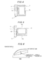
- the upper and lower face plates, front and rear face plates, or right and left face plates which have different wall thicknesses become different in temperature. This results in deformation of the structure, thus causing a spindle inclination (tilt). Specific examples of the spindle inclination are described with reference to FIGS. 4 to 6 .
- a spindle 1 is rotatably supported by a ram 4, and the ram 4 is supported by a structure 2 such as a column or cross rail.
- a tool 3 to machine a workpiece is mounted on the spindle 1, a tool 3 to machine a workpiece is mounted.
- front and rear face plates 2a and 2b are different in wall thickness from each other.
- the rate of change (convergence rate) in temperature A of the thin rear face plate 2b is higher than the rate of change (convergence rate) in temperature B of the thick front face plate 2a, thus resulting in a difference in temperature between the face plates 2a and 2b.
- the rear face plate 2b expands more than the front face plate 2a as indicated by dashed lines in FIG. 4 , and the structure 2 (front face plate 2a) tilts forward.
- a spindle 11 is rotatably supported by a ram 14, and the ram 14 is supported by a structure 12 such as a column or cross rail.
- a tool 13 to machine a workpiece is mounted on the spindle 11, a tool 13 to machine a workpiece is mounted.
- upper and lower face plates 12a and 12b are different in wall thickness from each other.
- the rate of change (convergence rate) in temperature A of the thin upper face plate 12b is higher than the rate of change (convergence rate) in temperature B of the thick lower face plate 12a, thus resulting in the temperature difference between the face plates 12a and 12b.
- the upper face plate 12b expands more than the lower face plate 12a as indicated by dashed lines in FIG. 5 , forming an inverted trapezoid.
- a front face plate 12c thereby tilts forward, and accordingly the spindle 11 supported by the structure 12 tilts (inclines) forward.
- the aforementioned first means can compensate the displacements of the tips of the tools 3 and 13 due to thermal expansion and contraction of the respective structures 2 and 12 but cannot compensate the inclination of the spindles 1 and 11.
- the inclination of the spindles 1 and 11 thermal deformation of the structures 2 and 12
- the insulator has a thickness optimal for preventing thermal deflection, but not optimal for preventing thermal twist.
- the thermal twist is a twist (thermal deformation) due to the temperature difference between a portion along one diagonal and a portion along the other diagonal, intersecting the one diagonal, of a rectangular face plate of a column or cross rail. A spindle inclination is also caused in this case.
- an object of the present invention is to provide: a spindle inclination detector capable of surely detecting spindle inclination with a simple configuration, performing high accuracy detection with temperature drifts canceled, and correcting the spindle inclination (thermal deformation of a structure); and a machine tool including the spindle inclination detector.
- a first aspect of the present invention to solve the aforementioned problems provides a spindle inclination detector equipped in a machine tool including: a spindle to which a tool for machining a workpiece is attached; and a structure supporting the spindle.
- the spindle inclination detector includes: a string hanging vertically with an upper end fixed to the structure and with a lower end attached to a weight; and a distance sensor attached to the string to measure a distance to a measurement portion of the structure, or a distance sensor attached to the structure to measure a distance to a measurement portion of the string.
- a second aspect of the present invention provides the spindle inclination detector according to the first aspect in which the distance sensor is a non-contact gap sensor.
- a third aspect of the present invention provides the spindle inclination detector according to the first or second aspect of the present invention, further including: a viscous fluid damper having a viscous fluid accommodated in a vessel. The weight is put in the viscous fluid of the viscous fluid damper.
- a fourth aspect of the present invention provides the spindle inclination detector according to any one of the first to third aspects of the present invention in which the string, the weight and the distance sensor are provided within the structure, or the string, the weight, the distance sensor and the viscous fluid damper are provided within the structure.
- a fifth aspect of the present invention provides a machine tool including the spindle inclination detector according to any one of the first to fourth aspects of the present invention.
- a sixth aspect of the present invention provides the machine tool according to the fifth aspect of the present invention, further including: temperature adjustment means which adjusts temperature of the structure; and a spindle inclination correction controller which corrects an inclination of the spindle due to the thermal deformation of the structure by correcting thermal deformation of the structure while controlling the temperature adjustment means on a basis of a distance measured by the distance sensor.
- a seventh aspect of the present invention provides the machine tool according to the sixth aspect of the present invention, in which the spindle inclination correction controller calculates an average distance measured by the distance sensor, and corrects an inclination of the spindle due to thermal deformation of the structure by correcting the thermal deformation of the structure while controlling the temperature adjustment means on a basis of the calculated average.
- An eighth aspect of the present invention provides the machine tool according to the sixth or seventh aspect, in which the spindle inclination correction controller determines whether the distance measured by the distance sensor is within a predetermined measurement range. When the measured distance is within the measurement range, the spindle inclination correction controller corrects an inclination of the spindle due to the thermal deformation of the structure by correcting the thermal deformation of the structure while controlling the temperature adjustment means on a basis of the measured distance.
- a ninth aspect of the present invention provides the machine tool according to any one of the sixth to eighth aspects, in which the temperature adjustment means is a Peltier device.
- the Peltier device is attached to at least one of portions of the structure, the portions being subject to temperature differences.
- a tenth aspect of the present invention provides the machine tool according to the ninth aspect of the present invention, in which the Peltier device is attached to each of the portions of the structure, the portions being subject to temperature differences. Additionally, the spindle inclination correction controller controls the Peltier device attached to a low-temperature portion among the portions subject to temperature differences so that the low-temperature portion can be heated, and controls the Peltier device attached to a high-temperature portion among the portions subject to temperature differences so that the high-temperature portion can be cooled.
- the spindle inclination detector includes: the string hanging vertically with the upper end fixed to the structure and with the lower end attached to the weight; and the distance sensor attached to the string to measure the distance to the measurement portion of the structure, or the distance sensor attached to the structure to measure the distance to the measurement portion of the string. Accordingly, if the structure is tilted by thermal deformation due to a temperature difference between portions (front and rear face plates; upper and lower face plates; or the like) of the structure to cause an inclination (tilt) of the spindle, there is a change in a relative positional relationship between the thermally deformed (tilted) structure and the vertically hanging string.
- the spindle inclination detector includes the non-contact gap sensor as the distance sensor. Accordingly, compared to the case of using a contact distance sensor, the distance sensor does not accidentally swing the string during the measurement of distance, thus performing more accurate distance measurement. Moreover, a commercially available gap sensor generally includes a function of canceling temperature drifts. Thus, when the gas sensor including such a function is used for the spindle inclination detector, it is possible to solve the problem of temperature drifts due to self-heating or changes in temperature.
- the spindle inclination detector includes the viscous fluid damper having the viscous fluid accommodated in the vessel, and the weight is put in the viscous fluid of the viscous fluid damper. Accordingly, the string and weight are less likely to be swung by external vibration or motion of the structure. Even when the string and weight are swung, such swing can be instantaneously attenuated by the viscous fluid. Therefore, the measurement of distance by the distance sensor can be performed with more accuracy.
- the members constituting the spindle inclination detector are provided within the structure. Accordingly, it is possible to easily prevent these members from being interfered with an operator or a structure around the machine tool without a protection cover or the like, thus making it possible to surely detect the spindle inclination.
- the machine tool includes the spindle inclination detector according to any one of the first to fourth aspects of the present invention. It is therefore possible to fabricate an excellent machine tool having the effect of any one of the first to fourth aspects of the present invention.
- the machine tool includes: the temperature adjustment means which adjusts temperature of the structure; and the spindle inclination correction controller which corrects the inclination of the spindle due to the thermal deformation of the structure by correcting the thermal deformation of the structure while controlling the temperature adjustment means on the basis of the distance measured by the distance sensor.
- the spindle inclination correction controller controls the temperature adjustment means on the basis of the distance, at this time, measured by the distance sensor while correcting the thermal deformation of the structure, thus making it possible to correct the spindle inclination.
- the spindle inclination correction controller calculates the average distance measured by the distance sensor and corrects the inclination of the spindle due to the thermal deformation of the structure by correcting the thermal deformation of the structure while controlling the temperature adjustment means on the basis of the calculated average. Accordingly, even when the string and weight are swung by external vibration or the like, and then the output of the distance sensor is fluctuated, such fluctuation is cancelled by averaging the distance measured by the distance sensor. This is because such fluctuation is nearly sinusoidal. It is therefore possible to more accurately correct the thermal deformation of the structure, and thereby correct the spindle inclination.
- the spindle inclination correction controller determines whether the distance measured by the distance sensor is within a predetermined measurement range. When the measured distance is within the measurement range, the spindle inclination correction controller corrects the inclination of the spindle due to the thermal deformation of the structure by correcting the thermal deformation of the structure while controlling the temperature adjustment means on the basis of the measured distance. Accordingly, even when the string and weight are greatly swung by motion of the structure, external vibration, or the like, and then the distance measured by the distance sensor greatly varies, the measured distance exceeding a predetermined measurement range (over range) is ignored. It is therefore possible to more accurately correct the thermal deformation of the structure, and thereby correct the spindle inclination.
- the temperature adjustment means is a Peltier device.
- the Peltier device is attached to at least one of portions of the structure, the portions being subject to temperature differences. Accordingly, the temperature of the structure can be easily adjusted by the Peltier device with high accuracy. It is therefore possible to correct the thermal deformation of the structure more easily and accurately, and thereby correct the spindle inclination. Moreover, since it is only necessary that the sheet-shaped Peltier device be attached to the structure, the installation operation is made with great ease.
- the Peltier device is attached to each of the portions of the structure, the portions being subject to temperature differences.
- the spindle inclination correction controller controls the Peltier device attached to the low-temperature portion among the portions subject to temperature differences so that the low-temperature portion can be heated, and controls the Peltier device attached to the high-temperature portion among the portions subject to temperature differences so that the high-temperature portion can be cooled. Accordingly, compared to the case of only heating the low-temperature portion or only cooling the high temperature portion with the Peltier device, it is possible to more easily correct the thermal deformation of the structure, and thereby correct the spindle inclination. Moreover, the amount of heat of the structure changes to a small extent, and the structure has little thermal expansion and contraction. Accordingly, it is not necessary to consider the thermal expansion and contraction of the structure, and thus it is only necessary to correct the spindle inclination.
- 21 machine tool; 22: bed; 23: table; 24: portal bridge; 25: cross rail; 26: saddle; 27: ram; 28: spindle; 29A and 29B: rail; 30: floor surface; 31A and 31B: wing; 32A and 32B: column; 33: top beam; 34A,34B,35A, and 35B: rail; 36: spindle motor; 37: tool; 41A and 41B: spindle inclination detector; 42A,42A-1,42A-2,42B,42B-1, and 42B-2: Peltier device; 43: string; 44: gap sensor; 45: weight; 46: oil damper; 47: vessel; 48: oil; 50: spindle inclination correction controller; 51: first measurement data processing section; 52: second measurement data processing section; 53: power supply
- FIG. 1 is a perspective view of a machine tool according to Embodiment 1 of the present invention
- FIG. 2 is a partially cut-away side view of the machine tool.
- a large-size machine tool 21 includes a bed 22, a table 23, a portal bridge 24, a cross rail 25, a saddle 26, a ram 27, and a spindle 28 as main structures.
- the bed 22 is fixed to a floor surface 30.
- a pair of rails 29A and 29B horizontally extending in a longitudinal direction (X-axis direction) of the bed 22.
- the table 23 is slidably attached to the rails 29A and 29B. Accordingly, the table 23 is guided by the rails 29A and 29B to be horizontally moved in the longitudinal direction (X-axis direction) of the bed 22 by non-illustrated drive means including a feeding screw mechanism.
- a workpiece to be machined by a tool 37 is placed on the table 23.
- the portal bridge 24 is a portal one including a pair of columns 32A and 32B and a top beam 33, and is installed so as to straddle the table 23.
- the columns 32A and 32B are respectively stood on a pair of wings 31A and 31B, which are horizontally protruded on the right and left sides of the bed 22.
- the columns 32A and 32B are positioned on the right and left side of the table 23, respectively.
- the top beam 33 connects the upper ends of the columns 32A and 32B to each other.
- a pair of rails 34A and 34B extending vertically (in a Z-axis direction) are provided, respectively.
- the cross rail 25 is horizontally placed on the front face plate 32a side of the columns 32A and 32B, and slidably attached to the rails 34A and 34B. Accordingly, the cross rail 25 is guided by the rails 34A and 34B to be moved vertically (in the Z-axis direction) by non-illustrated drive means including a feed screw mechanism.
- a pair of rails 35A and 35B horizontally extending in a longitudinal direction (Y-axis direction) of the cross rail 25.
- the saddle 26 is slidably attached to these rails 35A and 35B. Accordingly, the saddle 26 is guided by the rails 35A and 35B to be horizontally moved in the longitudinal direction (Y-axis direction) of the cross rail 25 by non-illustrated drive means including a feed screw mechanism.
- the ram 27 is slidably inserted into the saddle 26, and can be moved vertically (in the Z-axis direction) by non-illustrated drive means including a feed screw mechanism.
- the spindle 28 is rotatably provided in the ram 27 and extends vertically (in the Z-axis direction).
- a spindle motor 36 is attached to the upper end of the ram 27, and the spindle 28 is rotatably driven by the spindle motor 36.
- the tool 37 for machining such as milling or drilling is mounted on an end of the spindle 28.
- the tool 37 is rotated together with the spindle 28, and moved in the Z-axis direction or Y-axis direction together with the ram 27, cross rail 25, and saddle 26, while the workpiece on the table 23 is moved in the X-axis direction together with the table 23, thus performing machining such as milling or drilling for the workpiece.
- the front and rear face plates 32a and 32d of each of the columns 32A and 32B differ in wall thickness.
- the rate of change (convergence rate) in temperature of the thin rear face plate 32d is higher than the rate of change (convergence rate) in temperature of the thick front face plate 32a, thus resulting in the temperature difference between the face plates 32a and 32d.
- the rear face plate 32d expands more than the front face plate 32a as indicated by dashed lines in FIG. 2 (FIG.
- spindle inclination detectors 41A and 41B, Peltier devices 42A and 42B as temperature adjustment means, and a spindle inclination correction controller 50 are provided in order to detect and correct inclination of the spindle 28 due to thermal deformation (tilt) of the columns 32A and 32B.
- the spindle inclination detectors 41A and 41B are respectively provided within the columns 32A and 32B, which are hollow.
- the Peltier devices 42A and 42B are sheet-shaped, and attached to the rear face plates 32d of the columns 32A and 32B, respectively.
- the Peltier devices 42A and 42B are devices utilizing the Peltier effect. By switching the direction in which current flows, heat generation and heat absorption can be switched. Moreover, by adjusting the amount of current, the amount of heat generated or absorbed can be adjusted.
- the spindle inclination detector 41A equipped in the column 32A includes a string 43, a weight 45, a non-contact gap sensor 44 as a distance sensor, an oil damper 46 as a viscous fluid damper.
- the string 43 hangs vertically with the upper end fixed to a reinforcement 32b within the column 32A and with the lower end attached to the weight 45.
- the string 43 can be made of a proper material and have a proper thickness, but should have a low-rigidity so as to always hang vertically even if the structure (the reinforcement 32b of the column 32A in the example shown in the drawing) to which the upper end of the string 43 is fixed is tilted.
- the gap sensor 44 is attached to the string 43, and measures a distance L to the front face plate 32a of the column 32A (measurement portion).
- the measurement portion is not limited to a part of the front face plate 32a, and may be, for example, a measurement plate attached to the front face plate 32a.
- the gap sensor 44 may be attached to the front face plate 32a to measure a distance to the string 43 (measurement portion).
- the measurement portion is not limited to a part of the string 43, and may be, for example, a measurement plate attached to the string 43.
- the gap sensor 44 attached to the string 43 may measure a distance to the rear face plate 32d (measurement portion), or may be attached to the rear face plate 32d to measure a distance to the string 43 (measurement portion).
- the measurement portion is not limited to a part of the rear face plate 32d or a part of the string 43, and may be, for example, a measurement plate attached to the rear face plate 32d or string 43.
- the gap sensor 44 can be an eddy-current gap sensor, a capacitance gap sensor, an optical gap sensor which utilizes reflection of a laser beam, or the like. These gap sensors generally have a function of canceling temperature drifts with sufficient accuracy. Note that, in the case of using the eddy-current gap sensor, the material of the measurement portion needs to be metal in order to generate an eddy current. In the case of using the optical gap sensor, it is desirable that the material of the measurement portion have an excellent optical reflectivity.
- the columns 32A and 32B tilt forward due to thermal deformation. For this reason, in the case of measuring the distances to the front face plates 32a (measurement portions) with the gap sensors 44 attached to the strings 43 or measuring the distances to the strings 43 (measurement portions) with the gap sensors 44 attached to the front face plates 32a, the distances measured by the gap sensors 44 decrease according to thermal deformation (tilt) of the columns 32A and 32B.
- the distances measured by the gap sensors 44 increase according to thermal deformation (tilt) of the columns 32A and 32B.
- the oil damper 46 is provided on a lower face plate 32c of the column 32A, and accommodates oil 48 as a viscous fluid accommodated in a vessel 47.
- the weight 45 is put in the oil 48 in the vessel 47.
- the configuration of the spindle inclination detector 41B equipped in the column 32B is the same as that of the spindle inclination detector 41A equipped in the column 32A, and thus the concrete description is omitted.
- the spindle inclination correction controller 50 corrects the inclination (tilt) of the spindle 28 due to the thermal deformation (tilt) of the columns 32A and 32B by correcting the thermal deformation (tilt) of the columns 32A and 32B while controlling the Peltier devices 42A and 42B on the basis of the distances measured by the respective gap sensors 44.
- the spindle inclination correction controller 50 includes a first measurement data processing section 51, a second measurement data processing section 52, and a power supply 53.
- FIG. 2 shows only the relation between the spindle inclination correction controller 50 and spindle inclination detector 41A.
- the relation between the spindle inclination correction controller 50 and the spindle inclination detector 41B, which is not shown in the drawing, is the same as that in the case of the spindle inclination detector 41A.
- the strings 43 (weights 45) of the spindle inclination detectors 41A and 41B are sometimes swung to a large extent by motion of the saddle 26 and cross rail 25. Then, the output signals (measured distances) from the gap sensors 44 change to a large extent independently of the thermal deformation (tilt) of the columns 32A and 32B. However, the thermal deformation (tilt) of the columns 32A and 32B always occurs in order of hours, and thereby the measured distances change in order of hours. On the other hand, the large change in the measured distance due to the motion of the saddle 26 and cross rail 25 is temporary.
- the first measurement data processing section 51 determines whether the distance measured by each gap sensor 44 is within a predetermined measurement range. As a result, when it is determined that the measured distance exceeds the measurement range (over range), the measured distance is not outputted to the subsequent second measurement data processing section 52. Only when it is determined that the measured distance is within the predetermined measurement range, the measured distance is outputted to the subsequent second measurement data processing section 52. In other words, such a temporary change in the measured distance exceeding the measurement range (over range) is ignored. Note that, the measurement range should be wider than a range of variations in measured distance due to thermal deformation (tilt) of the columns 32A and 32B, and should be properly set by experiments or the like.
- the strings 43 (weights 45) of the spindle inclination detectors 41A and 41B are sometimes swung by vibration of the machine tool 21 due to external vibration, resulting in fluctuation of the output signals (measured distance) from the gap sensors 44. Note that, such fluctuation is nearly sinusoidal.
- the second measurement data processing section 52 therefore calculates an average distance measured by each gap sensor 44 and outputted from the first measurement data processing section 51.
- the number of hours during which data points used to calculate the average measurement data (distances measured by the gap sensors 44) are taken should be properly determined considering a period of the fluctuation on the basis of experiments or the like.
- the spindle inclination correction controller 50 of the example in the drawing performs both the measurement data processing by the first measurement data processing section 51 which ignores the temporary over range and the measurement data processing by the second measurement data processing section 52 which calculates the average of measured distances.
- the spindle inclination detector 41A is not limited to this, and may perform only one of the measurement data processing.
- the power supply 53 allows current to flow through each of the Peltier devices 42A and 42B in a predetermined direction on the basis of the average of the distances measured by the gap sensors 44 which are outputted from the second measurement data processing section 52. Note that, in the case where only the measurement data processing by the first measurement data processing section 51 is performed, when the distance measured by the each gap sensor 44 is within the measurement range, the power supply 53 allows current to flow through each of the Peltier devices 42A and 42B in the predetermined direction on the basis of the measured distance.
- the power supply 53 allows current to flow through each of the Peltier devices 42A and 42B in the predetermined direction directly on the basis of the distance measured by each gap sensor 44.
- each of the Peltier devices 42A and 42B is respectively attached to the rear face plate 32d of the corresponding column 32A and 32B.
- the power supply 53 allows current to flow through the Peltier devices 42A and 42B in such a direction that the Peltier devices 42A and 42B absorb heat.
- the rear face plates 32d are cooled by the heat absorption of the Peltier devices 42A and 42B, and the temperature of each rear face plate 32d is reduced by about 0.5°C, for example. Thereby, the thermal deformation (tilt) of the columns 32A and 32B is corrected, and thus the inclination of the spindle 28 is corrected.
- the power supply 53 allows current to flow through each of the Peltier devices 42A and 42B in such a direction that the Peltier devices 42A and 42B generate heat.
- the temperature of each front face plate 32a is increased by about 0.5°C, for example.
- the thermal deformation (tilt) of the columns 32A and 32B is corrected, and accordingly the inclination of the spindle 28 is corrected.
- a certain amount of current may be allowed to flow through each of the Peltier devices 42A and 42B when the following data reaches a set value: that is, the average distance measured by each gap sensor 44 (in the case where both the measurement data processings by the first and second measurement data processing sections 51 and 52 are performed, or only the measurement data processing by the second measurement data processing section 52 is performed) ; the distance measured by each gap sensor 44, which is within the measurement range (in the case where only the measurement data processing by the first measurement data processing section 51 is performed); or the distance measured by each gap sensor 44 (in the case where any measurement data processing by the first and second measurement data processing sections 51 and 52 is not performed).
- the current value to flow through each of the Peltier devices 42A and 42B may be adjusted (in other words, when the amount of change is increased, the current value is increased; when the amount of change is decreased, the current value is decreased).
- each of the spindle inclination detectors 41A and 41B is characterized by including: the string 43 which vertically hangs with the upper end fixed to the corresponding column 32A or 32B (the reinforcement 32b) and with the lower end attached to the weight 45; and the gap sensor 44 which is attached to the string 43 to measure the distance to the front face plate 32a (measurement portion) or rear face plate 32d (measurement portion) of the corresponding column 32A or 32B, or which is attached to the corresponding column 32A or 32B (front face plate 32a or rear face plate 32d) to measure the distance to the measurement portion of the string 43.
- each of the columns 32A and 32B tilts because of thermal deformation due to the temperature difference between the front and rear face plates 32a and 32d to cause an inclination (tilt) of the spindle 28, there is a change in the relative positional relationship between each of the thermally deformed (tilted) columns 32A and 32B (front and rear face plates 32a and 32d) and each of the vertically hanging strings 43.
- each of the spindle inclination detectors 41A and 41B is characterized by including the non-contact gap sensor 44 as the sensor to measure the distance. Accordingly, compared to the case of using a contact distance sensor, the distance sensor does not accidentally swing the string during the measurement of distance, thus performing more accurate distance measurement.
- the gas sensors 44 including the function of cancelling temperature drifts are used for the respective spindle inclination detectors 41A and 41B, it is possible to solve the problem of temperature drifts due to self-heating or changes in temperature.
- each of the spindle inclination detectors 41A and 41B is characterized by including the oil damper 46 accommodating the oil 48 accommodated in the vessel 47, and the weight 45 is put in the oil 48 of the oil damper 46. Accordingly, the string 43 and weight 45 are less likely to be swung by external vibration or motion of the cross rail 25. Even when the string 43 and weight 45 are swung, such swing can be instantaneously attenuated by the oil 48. Therefore, the measurement of distance by the gap sensors 44 can be performed with more accuracy.
- the spindle inclination detectors 41A and 41B according to Embodiment 1 is characterized in that the members constituting the spindle inclination detectors 41A and 41B (the strings 43, weights 45, gap sensors 44, and oil dampers 46) are provided in the columns 32A and 32B, respectively. Accordingly, it is possible to easily prevent these members from being interfered with an operator or a structure around the machine tool 21 without a protection cover or the like, thus making it possible to surely detect the spindle inclination.
- the machine tool 21 is characterized by including the spindle inclination detectors 41A and 41B having the above described structure. It is therefore possible to fabricate an excellent machine tool having the aforementioned effects.
- the machine tool 21 is characterized by including: the Peltier devices 42A and 42B respectively adjusting temperatures of the columns 32A and 32B; and the spindle inclination correction controller 50 which corrects the inclination of the spindle 28 due to the thermal deformation of the columns 32A and 32B by correcting the thermal deformation of the columns 32A and 32B while controlling the Peltier devices 42A and 42B on the basis of the average distance measured by the gap sensors 44.
- the spindle inclination correction controller 50 individually controls the Peltier devices 42A and 42B on the basis of the average, at this time, of the distances measured by the gap sensors 44 while correcting the thermal deformation of the columns 32A and 32B, and thus making it possible to correct the spindle inclination.
- each of the distances measured by the gap sensors 44 is within the predetermined measurement range, and only the measured distance within the measurement range is used for the control. Accordingly, even when the strings 43 and weights 45 are greatly swung by motion of the cross rail 25, external vibration, or the like, and then the distances measured by the gap sensors 44 greatly vary, the measured distance exceeding the measurement range (over range) is ignored. It is therefore possible to more accurately correct the thermal deformation of the columns 32A and 32B, and thereby correct the spindle inclination.
- the average distance measured by the gap sensors 44 are used for the control. Accordingly, even when the strings 43 and weights 45 are swung by external vibration or the like, and then the outputs of the gap sensors 44 are fluctuated, such fluctuations are cancelled by averaging the distances measured by the gap sensors 44. It is therefore possible to more accurately correct thermal deformation of the columns 32A and 32B, and thereby correct the spindle inclination.
- the Peltier devices 42A and 42B are used as the temperature adjustment means, and attached to the portions of the columns 32A and 32B (the front face plates 32a or rear face plates 32d), the portions being subject to temperature differences. Accordingly, the temperatures of the columns 32A and 32B can be easily adjusted by the Peltier devices 42A and 42B with high accuracy. It is therefore possible to more easily and accurately correct thermal deformation of the columns 32A and 32B, and thereby correct the spindle inclination. Moreover, since it is only necessary that the sheet-shaped Peltier devices 42A and 42B be attached to the columns 32A and 32B, the installation operation is made with great ease.
- the front face plates 32a or rear face plates 32d can be heated and cooled by the Peltier devices 42A and 42B with an accuracy of ⁇ 0.1°C as an example, it is possible to correct the thermal deformation (tilt) of the columns 32A and 32B within a range of, for example, ⁇ 100 ⁇ m/m with an accuracy of ⁇ 2 ⁇ m/m.
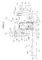
- FIG. 3 is a partially cut-away side view of a machine tool according to Embodiment 2 of the present invention.
- the entire configuration of the machine tool according to Embodiment 2 shown in FIG. 3 is the same as that of the machine tool according to Embodiment 1 shown in FIGS. 1 and 2 .
- the same parts as those in FIGS. 1 and 2 are donated by the same reference numerals.
- two Peltier devices 42A-1 and 42A-2 are attached to the front face plates 32a and rear face plates 32d of the column 32A, respectively, and two Peltier devices 42B-1 and 42B-2 are attached to the front face plates 32a and rear face plates 32d of the column 32B (see FIG. 1 ), respectively, which are not shown in the drawing.
- the power supply 53 of the spindle inclination correction controller 50 allows current to flow through each of the Peltier devices 42A-1, 42A-2, 42B-1, and 42B-2 in a predetermined direction on the basis of an average distance measured by each gap sensor 44 which is outputted from the second measurement data processing section 52. Note that, in the case where only the measurement data processing by the first measurement data processing section 51 is performed, when the distance measured by the each gap sensor 44 is within the measurement range, the power supply 53 allows current to flow through each of the Peltier devices 42A-1, 42A-2, 42B-1, and 42B-2 in the predetermined direction on the basis of the measured distance.
- the power supply 53 allows current to flow through each of the Peltier devices 42A-1, 42A-2, 42B-1, and 42B-2 in the predetermined direction directly on the basis of the distance measured by each gap sensor 44.
- the columns 32A and 32B is inclined forward by thermal deformation. Accordingly, current flows through the Peltier devices 42A-1 and 42B-1 attached to the respective front face plates 32a in such a direction that the Peltier devices 42A-1 and 42B-1 generate heat. Meanwhile, current flows through the Peltier devices 42A-2 and 42B-2 attached to the respective rear face plates 32d in such a direction that the Peltier devices 42A-2 and 42B-2 absorb heat.
- the front face plates 32a are heated by the heat generation of the respective Peltier devices 42A-1 and 42B-1 thereby to increase in temperatures of the front face plates 32a, and simultaneously the rear face plates 32d are cooled by the heat absorption of the Peltier devices 42A-2 and 42B-2 to decrease in temperatures of the rear face plates 32d.
- the thermal deformation (tilt) of the columns 32A and 32B are thus corrected, and accordingly the inclination of the spindle 28 is corrected.
- a certain amount of current may be allowed to flow through each of the Peltier devices 42A-1, 42A-2, 42B-1 and 42B-2 when the following data reaches a set value: that is, the average distance measured by each gap sensor 44 (in the case where both the measurement data processings by the first and second measurement data processing sections 51 and 52 are performed, or only the measurement data processing by the second measurement data processing section 52 is performed); the distance measured by each gap sensor 44, which is within the measurement range (in the case where only the measurement data processing by the first measurement data processing section 51 is performed); or the distance measured by each gap sensor 44 (in the case where any measurement data processing by the first and second measurement data processing sections 51 and 52 is not performed).
- the current value to flow through each of the Peltier devices 42A-1, 42A-2, 42B-1, and 42B-2 may be adjusted (in other words, when the amount of change is increased, the current value is increased; when the amount of change is decreased, the current value is decreased).
- the other configuration of the machine tool 21 according to Embodiment 2 is the same as that of the machine tool 21 according to Embodiment 1 (see FIGS. 1 and 2 ), and the detailed description thereof is omitted herein.
- the machine tool according to Embodiment 2 is characterized as follows. Specifically, the Peltier devices 42A-1 and 42B-1 and the Peltier devices 42A-2 and 42B-2 are respectively attached to the front face plates 32a and rear face plates 32d of the columns 32A and 32B, which are subject to temperature differences.
- the spindle inclination correction controller 50 controls the Peltier devices 42A-1 and 42B-1 attached to the front face plates 32a as low-temperature portions among the portions subject to temperature differences so that the front face plates 32a can be heated.
- the spindle inclination correction controller 50 controls the Peltier devices 42A-2 and 42B-2 attached to the rear face plates 32d as high-temperature portions among the portions subject to temperature differences so that the rear face plates 32d can be cooled.
- the spindle inclination detector according to the present invention is adopted to the large portal machine tool.
- the spindle inclination detector according to the present invention is not limited to this, and can be adopted to various types of machine tools such as a small machine tool, a machine tool with a single column, and a machine tool with a moving column.
- the spindle inclination detector is equipped in each column.
- the provision of the spindle inclination detector is not limited to this, and it is possible to provide the spindle inclination for various types of structures such as a saddle or cross rail supporting the spindle.
- the spindle inclination detector is provided for the cross rail, it is possible to detect not only spindle inclination due to thermal deformation (tilt) of the cross rail but also spindle inclination due to thermal deformation (tilt) of the columns because the cross rail is tilted together with the spindle by the thermal deformation (tilt) of the columns.
- the spindle inclination detector when the spindle inclination detector is provided for the saddle, it is possible to detect not only spindle inclination due to thermal deformation of the saddle but also spindle inclination due to thermal deformation (tilt) of the columns and thermal deformation (tilt) of the cross rail because the saddle is tilted together with the spindle by the thermal deformation (tilt) of the columns and the thermal deformation (tilt) of the cross rail.
- the spindle inclination detector may be provided for not only a structure which is thermally deformed (tilted) to directly cause spindle inclination but also other structures which are tilted together with the spindle by the thermal deformation of the structure which is thermally deformed to directly cause spindle inclination.
- the spindle inclination detector according to the present invention is not limited to such a case, and can be adopted for detection of the spindle inclination in cases where the upper and lower face plates have different wall thicknesses and where the right and left face plates have different wall thicknesses. Furthermore, the spindle inclination detector according to the present invention can be adopted for detection of the spindle inclination due to twist of the cross rail and the like.
- the Peltier device should be attached to one or both of a portion along one diagonal and a portion along the other diagonal, intersecting the one diagonal, of a rectangular face plate of the cross rail and the like.
- the Peltier device only needs to be attached to at least one of portions, subject to temperature differences, of a structure which is thermally deformed because of the temperature difference causing the spindle inclination.
- the temperature adjustment means is desirably, but not necessarily limited to, a Peltier device.
- the temperature adjustment means may be one which adjusts temperature of the structure with, for example, a temperature adjusting fluid (hot water, cold water, or the like).
- the present invention relates to a spindle inclination detector which detects an inclination (tilt) of a spindle and a machine tool including the spindle inclination detector, and is useful in applications to various machine tools such as a large portal machine tool.
Landscapes
- Engineering & Computer Science (AREA)
- Mechanical Engineering (AREA)
- Automatic Control Of Machine Tools (AREA)
- Machine Tool Sensing Apparatuses (AREA)
- Machine Tool Units (AREA)
Abstract
Description
- The present invention relates to a spindle inclination detector which detects an inclination (tilt) of a spindle and a machine tool including the spindle inclination detector.
- Conventional machine tools employ the following means in order to prevent reduction in machining accuracy due to thermal deformation of a structure.
-
- (1) First means is to measure the temperature of a main portion of a machine tool to compensate the position of the tool tip according to a change amount in the temperature of the main portion <see
Patent Document 1> - (2) Second means is to attach an insulator (a thermal insulating balancing wall panel) on a face plate of a structure such as a column or cross rail of a machine tool, the insulator having such a thickness that thermal equilibrium can be achieved <see
Patent Document 2> -
- Patent Document 1: Japanese Patent Application Laid-open Publication No.
2004-337996 - Patent Document 2: Japanese Patent Application Laid-open Publication No.
2003-145373 - In some machine tools, to minimize weight thereof while keeping necessary rigidity, face plates of a structure such as a column or cross rail supporting a spindle are made different in thickness between upper and lower face plates, between front and rear face plates, or between right and left face plates. In such a case, an air-temperature change around the machine tool leads to a difference in temperature change (convergence rate) among the face plates. A thinner face plate has a higher convergence rate. Accordingly, the upper and lower face plates, front and rear face plates, or right and left face plates which have different wall thicknesses become different in temperature. This results in deformation of the structure, thus causing a spindle inclination (tilt). Specific examples of the spindle inclination are described with reference to
FIGS. 4 to 6 . - In a machine tool shown in
FIG. 4 , aspindle 1 is rotatably supported by aram 4, and theram 4 is supported by astructure 2 such as a column or cross rail. On thespindle 1, atool 3 to machine a workpiece is mounted. In thisstructure 2, front andrear face plates structure 2, with respect to the change in ambient temperature around the machine tool as exemplified inFIG. 6 , the rate of change (convergence rate) in temperature A of the thinrear face plate 2b is higher than the rate of change (convergence rate) in temperature B of the thickfront face plate 2a, thus resulting in a difference in temperature between theface plates rear face plate 2b expands more than thefront face plate 2a as indicated by dashed lines inFIG. 4 , and the structure 2 (front face plate 2a) tilts forward. Thespindle 1, which is supported by thestructure 2, accordingly tilts (inclines) forward. - In a machine tool shown in
FIG. 5 , aspindle 11 is rotatably supported by aram 14, and theram 14 is supported by astructure 12 such as a column or cross rail. On thespindle 11, atool 13 to machine a workpiece is mounted. In thisstructure 12, upper andlower face plates structure 12, with respect to the change in ambient temperature around the machine tool as exemplified inFIG. 6 , the rate of change (convergence rate) in temperature A of the thinupper face plate 12b is higher than the rate of change (convergence rate) in temperature B of the thicklower face plate 12a, thus resulting in the temperature difference between theface plates upper face plate 12b expands more than thelower face plate 12a as indicated by dashed lines inFIG. 5 , forming an inverted trapezoid. Afront face plate 12c thereby tilts forward, and accordingly thespindle 11 supported by thestructure 12 tilts (inclines) forward. - Against this problem, the aforementioned first means can compensate the displacements of the tips of the
tools respective structures spindles spindles 1 and 11 (thermal deformation of thestructures 2 and 12) cannot be detected, and thereby the inclination of thespindles spindles spindles 1 and 11 (the thermal deformation of the structures) cannot be corrected. Note that, the thermal twist is a twist (thermal deformation) due to the temperature difference between a portion along one diagonal and a portion along the other diagonal, intersecting the one diagonal, of a rectangular face plate of a column or cross rail. A spindle inclination is also caused in this case. - Incidentally, as means for detecting a spindle inclination, it is considerable to measure a degree of a tilt with an electronic level meter such as an accelerator sensor. However, in the electronic level meter, temperature drifts occur due to self-heating or a change in temperature, and thus the electronic level meter has a low detection accuracy. Accordingly, the electronic level meter cannot detect a slight spindle inclination.
- In the light of the aforementioned circumferences, an object of the present invention is to provide: a spindle inclination detector capable of surely detecting spindle inclination with a simple configuration, performing high accuracy detection with temperature drifts canceled, and correcting the spindle inclination (thermal deformation of a structure); and a machine tool including the spindle inclination detector.
- A first aspect of the present invention to solve the aforementioned problems provides a spindle inclination detector equipped in a machine tool including: a spindle to which a tool for machining a workpiece is attached; and a structure supporting the spindle. The spindle inclination detector includes: a string hanging vertically with an upper end fixed to the structure and with a lower end attached to a weight; and a distance sensor attached to the string to measure a distance to a measurement portion of the structure, or a distance sensor attached to the structure to measure a distance to a measurement portion of the string.
- A second aspect of the present invention provides the spindle inclination detector according to the first aspect in which the distance sensor is a non-contact gap sensor.
- A third aspect of the present invention provides the spindle inclination detector according to the first or second aspect of the present invention, further including: a viscous fluid damper having a viscous fluid accommodated in a vessel. The weight is put in the viscous fluid of the viscous fluid damper.
- A fourth aspect of the present invention provides the spindle inclination detector according to any one of the first to third aspects of the present invention in which the string, the weight and the distance sensor are provided within the structure, or the string, the weight, the distance sensor and the viscous fluid damper are provided within the structure.
- A fifth aspect of the present invention provides a machine tool including the spindle inclination detector according to any one of the first to fourth aspects of the present invention.
- A sixth aspect of the present invention provides the machine tool according to the fifth aspect of the present invention, further including: temperature adjustment means which adjusts temperature of the structure; and a spindle inclination correction controller which corrects an inclination of the spindle due to the thermal deformation of the structure by correcting thermal deformation of the structure while controlling the temperature adjustment means on a basis of a distance measured by the distance sensor.
- A seventh aspect of the present invention provides the machine tool according to the sixth aspect of the present invention, in which the spindle inclination correction controller calculates an average distance measured by the distance sensor, and corrects an inclination of the spindle due to thermal deformation of the structure by correcting the thermal deformation of the structure while controlling the temperature adjustment means on a basis of the calculated average.
- An eighth aspect of the present invention provides the machine tool according to the sixth or seventh aspect, in which the spindle inclination correction controller determines whether the distance measured by the distance sensor is within a predetermined measurement range. When the measured distance is within the measurement range, the spindle inclination correction controller corrects an inclination of the spindle due to the thermal deformation of the structure by correcting the thermal deformation of the structure while controlling the temperature adjustment means on a basis of the measured distance.
- A ninth aspect of the present invention provides the machine tool according to any one of the sixth to eighth aspects, in which the temperature adjustment means is a Peltier device. The Peltier device is attached to at least one of portions of the structure, the portions being subject to temperature differences.
- A tenth aspect of the present invention provides the machine tool according to the ninth aspect of the present invention, in which the Peltier device is attached to each of the portions of the structure, the portions being subject to temperature differences. Additionally, the spindle inclination correction controller controls the Peltier device attached to a low-temperature portion among the portions subject to temperature differences so that the low-temperature portion can be heated, and controls the Peltier device attached to a high-temperature portion among the portions subject to temperature differences so that the high-temperature portion can be cooled.
- The spindle inclination detector according to the first aspect of the present invention includes: the string hanging vertically with the upper end fixed to the structure and with the lower end attached to the weight; and the distance sensor attached to the string to measure the distance to the measurement portion of the structure, or the distance sensor attached to the structure to measure the distance to the measurement portion of the string. Accordingly, if the structure is tilted by thermal deformation due to a temperature difference between portions (front and rear face plates; upper and lower face plates; or the like) of the structure to cause an inclination (tilt) of the spindle, there is a change in a relative positional relationship between the thermally deformed (tilted) structure and the vertically hanging string. Specifically, there is a change in the distance between the distance sensor attached to the string and the measurement portion of the structure or distance between the distance sensor attached to the structure and the measurement portion of the string. Such a change in distance is measured by the distance sensor. In other words, the distance measured by the distance sensor varies. It is therefore possible to detect thermal deformation (tilt) of the structure, that is, inclination (tilt) of the spindle, on the basis of the change in distance measured by the distance sensor. Accordingly, it is possible to surely detect the spindle inclination with such a simple structure at low cost.
- Moreover, according to the second aspect of the present invention, the spindle inclination detector includes the non-contact gap sensor as the distance sensor. Accordingly, compared to the case of using a contact distance sensor, the distance sensor does not accidentally swing the string during the measurement of distance, thus performing more accurate distance measurement. Moreover, a commercially available gap sensor generally includes a function of canceling temperature drifts. Thus, when the gas sensor including such a function is used for the spindle inclination detector, it is possible to solve the problem of temperature drifts due to self-heating or changes in temperature.
- Still moreover, according to the third aspect of the present invention, the spindle inclination detector includes the viscous fluid damper having the viscous fluid accommodated in the vessel, and the weight is put in the viscous fluid of the viscous fluid damper. Accordingly, the string and weight are less likely to be swung by external vibration or motion of the structure. Even when the string and weight are swung, such swing can be instantaneously attenuated by the viscous fluid. Therefore, the measurement of distance by the distance sensor can be performed with more accuracy.
- Still moreover, in the spindle inclination detector according to the fourth aspect of the present invention, the members constituting the spindle inclination detector (the string, weight, and distance sensor; or the string, weight, distance sensor, and viscous fluid damper) are provided within the structure. Accordingly, it is possible to easily prevent these members from being interfered with an operator or a structure around the machine tool without a protection cover or the like, thus making it possible to surely detect the spindle inclination.
- According to the fifth aspect of the present invention, the machine tool includes the spindle inclination detector according to any one of the first to fourth aspects of the present invention. It is therefore possible to fabricate an excellent machine tool having the effect of any one of the first to fourth aspects of the present invention.
- Moreover, according to the sixth aspect of the present invention, the machine tool includes: the temperature adjustment means which adjusts temperature of the structure; and the spindle inclination correction controller which corrects the inclination of the spindle due to the thermal deformation of the structure by correcting the thermal deformation of the structure while controlling the temperature adjustment means on the basis of the distance measured by the distance sensor. Accordingly, even when the structure is tilted by the thermal deformation due to the temperature difference between the portions (front and rear face plates, upper and lower face plates, or the like) of the structure to cause an inclination (tilt) of the spindle, the spindle inclination correction controller controls the temperature adjustment means on the basis of the distance, at this time, measured by the distance sensor while correcting the thermal deformation of the structure, thus making it possible to correct the spindle inclination.
- Moreover, in the machine tool according to the seventh aspect of the present invention, the spindle inclination correction controller calculates the average distance measured by the distance sensor and corrects the inclination of the spindle due to the thermal deformation of the structure by correcting the thermal deformation of the structure while controlling the temperature adjustment means on the basis of the calculated average. Accordingly, even when the string and weight are swung by external vibration or the like, and then the output of the distance sensor is fluctuated, such fluctuation is cancelled by averaging the distance measured by the distance sensor. This is because such fluctuation is nearly sinusoidal. It is therefore possible to more accurately correct the thermal deformation of the structure, and thereby correct the spindle inclination.
- Still moreover, in the machine tool according to the eighth aspect of the present invention, the spindle inclination correction controller determines whether the distance measured by the distance sensor is within a predetermined measurement range. When the measured distance is within the measurement range, the spindle inclination correction controller corrects the inclination of the spindle due to the thermal deformation of the structure by correcting the thermal deformation of the structure while controlling the temperature adjustment means on the basis of the measured distance. Accordingly, even when the string and weight are greatly swung by motion of the structure, external vibration, or the like, and then the distance measured by the distance sensor greatly varies, the measured distance exceeding a predetermined measurement range (over range) is ignored. It is therefore possible to more accurately correct the thermal deformation of the structure, and thereby correct the spindle inclination.
- In the machine tool according to the ninth aspect of the present invention, the temperature adjustment means is a Peltier device. The Peltier device is attached to at least one of portions of the structure, the portions being subject to temperature differences. Accordingly, the temperature of the structure can be easily adjusted by the Peltier device with high accuracy. It is therefore possible to correct the thermal deformation of the structure more easily and accurately, and thereby correct the spindle inclination. Moreover, since it is only necessary that the sheet-shaped Peltier device be attached to the structure, the installation operation is made with great ease.
- In the machine tool according to the tenth aspect of the present invention, the Peltier device is attached to each of the portions of the structure, the portions being subject to temperature differences. Additionally, the spindle inclination correction controller controls the Peltier device attached to the low-temperature portion among the portions subject to temperature differences so that the low-temperature portion can be heated, and controls the Peltier device attached to the high-temperature portion among the portions subject to temperature differences so that the high-temperature portion can be cooled. Accordingly, compared to the case of only heating the low-temperature portion or only cooling the high temperature portion with the Peltier device, it is possible to more easily correct the thermal deformation of the structure, and thereby correct the spindle inclination. Moreover, the amount of heat of the structure changes to a small extent, and the structure has little thermal expansion and contraction. Accordingly, it is not necessary to consider the thermal expansion and contraction of the structure, and thus it is only necessary to correct the spindle inclination.
-
- [
FIG. 1] FIG. 1 is a perspective view of a machine tool according toEmbodiment 1 of the present invention. - [
FIG. 2] FIG. 2 is a partially cut-away side view of the machine tool. - [
FIG. 3] FIG. 3 is a partially cut-away side view of a machine tool according toEmbodiment 2 of the present invention. - [
FIG. 4] FIG. 4 is an explanatory view showing a concrete example of a spindle inclination. - [
FIG. 5] FIG. 5 is an explanatory view showing another concrete example of a spindle inclination. - [
FIG. 6] FIG. 6 is an explanatory view for exemplifying changes in temperature of face plates which are different in wall thicknesses from each other with respect to changes in air temperature. - 21: machine tool; 22: bed; 23: table; 24: portal bridge; 25: cross rail; 26: saddle; 27: ram; 28: spindle; 29A and 29B: rail; 30: floor surface; 31A and 31B: wing; 32A and 32B: column; 33: top beam; 34A,34B,35A, and 35B: rail; 36: spindle motor; 37: tool; 41A and 41B: spindle inclination detector; 42A,42A-1,42A-2,42B,42B-1, and 42B-2: Peltier device; 43: string; 44: gap sensor; 45: weight; 46: oil damper; 47: vessel; 48: oil; 50: spindle inclination correction controller; 51: first measurement data processing section; 52: second measurement data processing section; 53: power supply
- Hereinafter, a specific description is given of embodiments of the present invention with reference to the drawings.
-
FIG. 1 is a perspective view of a machine tool according toEmbodiment 1 of the present invention, andFIG. 2 is a partially cut-away side view of the machine tool. - As shown in
FIGS. 1 and2 , a large-size machine tool 21 includes abed 22, a table 23, aportal bridge 24, across rail 25, asaddle 26, aram 27, and aspindle 28 as main structures. - The
bed 22 is fixed to afloor surface 30. On an upper surface of thebed 22, provided are a pair ofrails bed 22. The table 23 is slidably attached to therails rails bed 22 by non-illustrated drive means including a feeding screw mechanism. Although omitted in the drawing, a workpiece to be machined by atool 37 is placed on the table 23. - The
portal bridge 24 is a portal one including a pair ofcolumns top beam 33, and is installed so as to straddle the table 23. Thecolumns wings bed 22. Thecolumns top beam 33 connects the upper ends of thecolumns - On front faces (
front face plates 32a) of thecolumns rails cross rail 25 is horizontally placed on thefront face plate 32a side of thecolumns rails cross rail 25 is guided by therails - On a front face of the
cross rail 25, provided are a pair ofrails cross rail 25. Thesaddle 26 is slidably attached to theserails saddle 26 is guided by therails cross rail 25 by non-illustrated drive means including a feed screw mechanism. - The
ram 27 is slidably inserted into thesaddle 26, and can be moved vertically (in the Z-axis direction) by non-illustrated drive means including a feed screw mechanism. Thespindle 28 is rotatably provided in theram 27 and extends vertically (in the Z-axis direction). Aspindle motor 36 is attached to the upper end of theram 27, and thespindle 28 is rotatably driven by thespindle motor 36. Thetool 37 for machining such as milling or drilling is mounted on an end of thespindle 28. - Accordingly, in this
machine tool 21, thetool 37 is rotated together with thespindle 28, and moved in the Z-axis direction or Y-axis direction together with theram 27,cross rail 25, and saddle 26, while the workpiece on the table 23 is moved in the X-axis direction together with the table 23, thus performing machining such as milling or drilling for the workpiece. - To minimize weight of the
machine tool 21 while keeping necessary rigidity, the front andrear face plates columns such columns FIG. 6 , for example, the rate of change (convergence rate) in temperature of the thinrear face plate 32d is higher than the rate of change (convergence rate) in temperature of the thickfront face plate 32a, thus resulting in the temperature difference between theface plates machine tool 21 increases, therear face plate 32d expands more than thefront face plate 32a as indicated by dashed lines inFIG. 2 (FIG. 2 shows only thetilting column 32A, but thecolumn 32B tilts in a similar manner), and thecolumns front face plates 32a) thus tilt forward. Thespindle 28, which is supported by thecolumns front face plates 32a), thus tilts (inclines) forward. - In the
machine tool 21,spindle inclination detectors Peltier devices inclination correction controller 50 are provided in order to detect and correct inclination of thespindle 28 due to thermal deformation (tilt) of thecolumns - The
spindle inclination detectors columns Peltier devices rear face plates 32d of thecolumns Peltier devices - As shown in
FIG. 2 , thespindle inclination detector 41A equipped in thecolumn 32A includes astring 43, aweight 45, anon-contact gap sensor 44 as a distance sensor, anoil damper 46 as a viscous fluid damper. Thestring 43 hangs vertically with the upper end fixed to areinforcement 32b within thecolumn 32A and with the lower end attached to theweight 45. Thestring 43 can be made of a proper material and have a proper thickness, but should have a low-rigidity so as to always hang vertically even if the structure (thereinforcement 32b of thecolumn 32A in the example shown in the drawing) to which the upper end of thestring 43 is fixed is tilted. - The
gap sensor 44 is attached to thestring 43, and measures a distance L to thefront face plate 32a of thecolumn 32A (measurement portion). In this case, the measurement portion is not limited to a part of thefront face plate 32a, and may be, for example, a measurement plate attached to thefront face plate 32a. Thegap sensor 44 may be attached to thefront face plate 32a to measure a distance to the string 43 (measurement portion). In this case, the measurement portion is not limited to a part of thestring 43, and may be, for example, a measurement plate attached to thestring 43. Furthermore, thegap sensor 44 attached to thestring 43 may measure a distance to therear face plate 32d (measurement portion), or may be attached to therear face plate 32d to measure a distance to the string 43 (measurement portion). In this case also, the measurement portion is not limited to a part of therear face plate 32d or a part of thestring 43, and may be, for example, a measurement plate attached to therear face plate 32d orstring 43. - The
gap sensor 44 can be an eddy-current gap sensor, a capacitance gap sensor, an optical gap sensor which utilizes reflection of a laser beam, or the like. These gap sensors generally have a function of canceling temperature drifts with sufficient accuracy. Note that, in the case of using the eddy-current gap sensor, the material of the measurement portion needs to be metal in order to generate an eddy current. In the case of using the optical gap sensor, it is desirable that the material of the measurement portion have an excellent optical reflectivity. - In the example shown in the drawing, the
columns front face plates 32a (measurement portions) with thegap sensors 44 attached to thestrings 43 or measuring the distances to the strings 43 (measurement portions) with thegap sensors 44 attached to thefront face plates 32a, the distances measured by thegap sensors 44 decrease according to thermal deformation (tilt) of thecolumns rear face plates 32d (measurement portions) with thegap sensors 44 attached to thestrings 43 or measuring the distances to the strings 43 (measurement portions) with thegap sensors 44 attached to therear face plates 32d, the distances measured by thegap sensors 44 increase according to thermal deformation (tilt) of thecolumns - The
oil damper 46 is provided on alower face plate 32c of thecolumn 32A, and accommodatesoil 48 as a viscous fluid accommodated in avessel 47. Theweight 45 is put in theoil 48 in thevessel 47. Thus, even if theweight 45 swings together with thestring 43 because of external vibration or the like, the swing of theweight 45 andstring 43 is attenuated by theoil 48 of theoil damper 46 in a short time. - The configuration of the
spindle inclination detector 41B equipped in thecolumn 32B is the same as that of thespindle inclination detector 41A equipped in thecolumn 32A, and thus the concrete description is omitted. - Distance measurement signals of each
gap sensor 44 of thespindle inclination detectors inclination correction controller 50. The spindleinclination correction controller 50 corrects the inclination (tilt) of thespindle 28 due to the thermal deformation (tilt) of thecolumns columns Peltier devices respective gap sensors 44. - To be specific, the spindle
inclination correction controller 50 includes a first measurementdata processing section 51, a second measurementdata processing section 52, and apower supply 53. Note thatFIG. 2 shows only the relation between the spindleinclination correction controller 50 andspindle inclination detector 41A. The relation between the spindleinclination correction controller 50 and thespindle inclination detector 41B, which is not shown in the drawing, is the same as that in the case of thespindle inclination detector 41A. - The strings 43 (weights 45) of the
spindle inclination detectors saddle 26 andcross rail 25. Then, the output signals (measured distances) from thegap sensors 44 change to a large extent independently of the thermal deformation (tilt) of thecolumns columns saddle 26 andcross rail 25 is temporary. - For this reason, the first measurement
data processing section 51 determines whether the distance measured by eachgap sensor 44 is within a predetermined measurement range. As a result, when it is determined that the measured distance exceeds the measurement range (over range), the measured distance is not outputted to the subsequent second measurementdata processing section 52. Only when it is determined that the measured distance is within the predetermined measurement range, the measured distance is outputted to the subsequent second measurementdata processing section 52. In other words, such a temporary change in the measured distance exceeding the measurement range (over range) is ignored. Note that, the measurement range should be wider than a range of variations in measured distance due to thermal deformation (tilt) of thecolumns - Moreover, the strings 43 (weights 45) of the
spindle inclination detectors machine tool 21 due to external vibration, resulting in fluctuation of the output signals (measured distance) from thegap sensors 44. Note that, such fluctuation is nearly sinusoidal. - For this reason, the second measurement
data processing section 52 therefore calculates an average distance measured by eachgap sensor 44 and outputted from the first measurementdata processing section 51. In this case, the number of hours during which data points used to calculate the average measurement data (distances measured by the gap sensors 44) are taken should be properly determined considering a period of the fluctuation on the basis of experiments or the like. - Note that, the spindle
inclination correction controller 50 of the example in the drawing performs both the measurement data processing by the first measurementdata processing section 51 which ignores the temporary over range and the measurement data processing by the second measurementdata processing section 52 which calculates the average of measured distances. However, thespindle inclination detector 41A is not limited to this, and may perform only one of the measurement data processing. - The
power supply 53 allows current to flow through each of thePeltier devices gap sensors 44 which are outputted from the second measurementdata processing section 52. Note that, in the case where only the measurement data processing by the first measurementdata processing section 51 is performed, when the distance measured by the eachgap sensor 44 is within the measurement range, thepower supply 53 allows current to flow through each of thePeltier devices data processing section 51 and the second measurementdata processing section 52 is not performed, thepower supply 53 allows current to flow through each of thePeltier devices gap sensor 44. - In the example shown in the drawing, each of the
Peltier devices rear face plate 32d of thecorresponding column columns power supply 53 allows current to flow through thePeltier devices Peltier devices rear face plates 32d are cooled by the heat absorption of thePeltier devices rear face plate 32d is reduced by about 0.5°C, for example. Thereby, the thermal deformation (tilt) of thecolumns spindle 28 is corrected. It is needless say that, in the case of attaching thePeltier devices front face plates 32a, thepower supply 53 allows current to flow through each of thePeltier devices Peltier devices Peltier devices front face plate 32a is increased by about 0.5°C, for example. Thus, the thermal deformation (tilt) of thecolumns spindle 28 is corrected. - Note that, in this case, for example, a certain amount of current may be allowed to flow through each of the
Peltier devices data processing sections data processing section 52 is performed) ; the distance measured by eachgap sensor 44, which is within the measurement range (in the case where only the measurement data processing by the first measurementdata processing section 51 is performed); or the distance measured by each gap sensor 44 (in the case where any measurement data processing by the first and second measurementdata processing sections gap sensor 44, an amount of change in distance measured by eachgap sensor 44, which is within the measurement range, or an amount of change in distance measured by eachgap sensor 44, the current value to flow through each of thePeltier devices - As described above, according to the
Embodiment 1, each of thespindle inclination detectors string 43 which vertically hangs with the upper end fixed to thecorresponding column reinforcement 32b) and with the lower end attached to theweight 45; and thegap sensor 44 which is attached to thestring 43 to measure the distance to thefront face plate 32a (measurement portion) orrear face plate 32d (measurement portion) of thecorresponding column corresponding column front face plate 32a orrear face plate 32d) to measure the distance to the measurement portion of thestring 43. Accordingly, if each of thecolumns rear face plates spindle 28, there is a change in the relative positional relationship between each of the thermally deformed (tilted)columns rear face plates strings 43. Specifically, there is a change in the distance between eachgap sensor 44 attached to eachstring 43 and the measurement portion of thecorresponding column front face plate 32a orrear face plate 32d), or distance between eachgap sensor 44 attached to thecorresponding column front face plate 32a orrear face plate 32d) and the measurement portion at thestring 43. Then, such a change in the distance is measured by each gap sensor. In other words, the distance measured by eachgap sensor 44 changes. It is therefore possible to detect thermal deformation (tilt) of each of thecolumns spindle 28, on the basis of the change in the distances measured by thegap sensors 44. Accordingly, it is possible to surely detect the spindle inclination with such a simple structure at low cost. - Moreover, according to
Embodiment 1, each of thespindle inclination detectors non-contact gap sensor 44 as the sensor to measure the distance. Accordingly, compared to the case of using a contact distance sensor, the distance sensor does not accidentally swing the string during the measurement of distance, thus performing more accurate distance measurement. When thegas sensors 44 including the function of cancelling temperature drifts are used for the respectivespindle inclination detectors - Still moreover, according to
Embodiment 1, each of thespindle inclination detectors oil damper 46 accommodating theoil 48 accommodated in thevessel 47, and theweight 45 is put in theoil 48 of theoil damper 46. Accordingly, thestring 43 andweight 45 are less likely to be swung by external vibration or motion of thecross rail 25. Even when thestring 43 andweight 45 are swung, such swing can be instantaneously attenuated by theoil 48. Therefore, the measurement of distance by thegap sensors 44 can be performed with more accuracy. - Still moreover, the
spindle inclination detectors Embodiment 1 is characterized in that the members constituting thespindle inclination detectors strings 43,weights 45,gap sensors 44, and oil dampers 46) are provided in thecolumns machine tool 21 without a protection cover or the like, thus making it possible to surely detect the spindle inclination. - In addition, according to
Embodiment 1, themachine tool 21 is characterized by including thespindle inclination detectors - Moreover, according to
Embodiment 1, themachine tool 21 is characterized by including: thePeltier devices columns inclination correction controller 50 which corrects the inclination of thespindle 28 due to the thermal deformation of thecolumns columns Peltier devices gap sensors 44. Accordingly, even when thecolumns rear face plates spindle 28, the spindleinclination correction controller 50 individually controls thePeltier devices gap sensors 44 while correcting the thermal deformation of thecolumns - Additionally, it is determined whether each of the distances measured by the
gap sensors 44 is within the predetermined measurement range, and only the measured distance within the measurement range is used for the control. Accordingly, even when thestrings 43 andweights 45 are greatly swung by motion of thecross rail 25, external vibration, or the like, and then the distances measured by thegap sensors 44 greatly vary, the measured distance exceeding the measurement range (over range) is ignored. It is therefore possible to more accurately correct the thermal deformation of thecolumns - Moreover, the average distance measured by the
gap sensors 44 are used for the control. Accordingly, even when thestrings 43 andweights 45 are swung by external vibration or the like, and then the outputs of thegap sensors 44 are fluctuated, such fluctuations are cancelled by averaging the distances measured by thegap sensors 44. It is therefore possible to more accurately correct thermal deformation of thecolumns - Furthermore, it is characterized in that the
Peltier devices columns front face plates 32a orrear face plates 32d), the portions being subject to temperature differences. Accordingly, the temperatures of thecolumns Peltier devices columns Peltier devices columns front face plates 32a orrear face plates 32d can be heated and cooled by thePeltier devices columns -
FIG. 3 is a partially cut-away side view of a machine tool according toEmbodiment 2 of the present invention. The entire configuration of the machine tool according toEmbodiment 2 shown inFIG. 3 is the same as that of the machine tool according toEmbodiment 1 shown inFIGS. 1 and2 . InFIG. 3 , the same parts as those inFIGS. 1 and2 are donated by the same reference numerals. - As shown in
FIG. 3 , in themachine tool 21 according toEmbodiment 2, twoPeltier devices 42A-1 and 42A-2 are attached to thefront face plates 32a andrear face plates 32d of thecolumn 32A, respectively, and twoPeltier devices 42B-1 and 42B-2 are attached to thefront face plates 32a andrear face plates 32d of thecolumn 32B (seeFIG. 1 ), respectively, which are not shown in the drawing. - The
power supply 53 of the spindleinclination correction controller 50 allows current to flow through each of thePeltier devices 42A-1, 42A-2, 42B-1, and 42B-2 in a predetermined direction on the basis of an average distance measured by eachgap sensor 44 which is outputted from the second measurementdata processing section 52. Note that, in the case where only the measurement data processing by the first measurementdata processing section 51 is performed, when the distance measured by the eachgap sensor 44 is within the measurement range, thepower supply 53 allows current to flow through each of thePeltier devices 42A-1, 42A-2, 42B-1, and 42B-2 in the predetermined direction on the basis of the measured distance. Meanwhile, in the case where any measurement data processing by the first measurementdata processing section 51 and the second measurementdata processing section 52 is not performed, thepower supply 53 allows current to flow through each of thePeltier devices 42A-1, 42A-2, 42B-1, and 42B-2 in the predetermined direction directly on the basis of the distance measured by eachgap sensor 44. - In the example shown in the drawing, the
columns Peltier devices 42A-1 and 42B-1 attached to the respectivefront face plates 32a in such a direction that thePeltier devices 42A-1 and 42B-1 generate heat. Meanwhile, current flows through thePeltier devices 42A-2 and 42B-2 attached to the respectiverear face plates 32d in such a direction that thePeltier devices 42A-2 and 42B-2 absorb heat. Thefront face plates 32a are heated by the heat generation of therespective Peltier devices 42A-1 and 42B-1 thereby to increase in temperatures of thefront face plates 32a, and simultaneously therear face plates 32d are cooled by the heat absorption of thePeltier devices 42A-2 and 42B-2 to decrease in temperatures of therear face plates 32d. The thermal deformation (tilt) of thecolumns spindle 28 is corrected. - Note that, in this case as similar to
Embodiment 1, a certain amount of current may be allowed to flow through each of thePeltier devices 42A-1, 42A-2, 42B-1 and 42B-2 when the following data reaches a set value: that is, the average distance measured by each gap sensor 44 (in the case where both the measurement data processings by the first and second measurementdata processing sections data processing section 52 is performed); the distance measured by eachgap sensor 44, which is within the measurement range (in the case where only the measurement data processing by the first measurementdata processing section 51 is performed); or the distance measured by each gap sensor 44 (in the case where any measurement data processing by the first and second measurementdata processing sections gap sensor 44, an amount of change in the distance measured by eachgap sensor 44, which is within the measurement range, or an amount of change in distance measured by eachgap sensor 44, the current value to flow through each of thePeltier devices 42A-1, 42A-2, 42B-1, and 42B-2 may be adjusted (in other words, when the amount of change is increased, the current value is increased; when the amount of change is decreased, the current value is decreased). - Note that, the other configuration of the
machine tool 21 according toEmbodiment 2 is the same as that of themachine tool 21 according to Embodiment 1 (seeFIGS. 1 and2 ), and the detailed description thereof is omitted herein. - As described above, the machine tool according to
Embodiment 2 is characterized as follows. Specifically, thePeltier devices 42A-1 and 42B-1 and thePeltier devices 42A-2 and 42B-2 are respectively attached to thefront face plates 32a andrear face plates 32d of thecolumns inclination correction controller 50 controls thePeltier devices 42A-1 and 42B-1 attached to thefront face plates 32a as low-temperature portions among the portions subject to temperature differences so that thefront face plates 32a can be heated. The spindleinclination correction controller 50 controls thePeltier devices 42A-2 and 42B-2 attached to therear face plates 32d as high-temperature portions among the portions subject to temperature differences so that therear face plates 32d can be cooled. Accordingly, compared to the case of only heating the low-temperature portions (thefront face plates 32a) with the Peltier devices or only cooling the high-temperature portions (therear face plates 32d) with the Peltier devices, it is possible to easily correct the thermal deformation of thecolumns columns columns columns - Note that, the above description is given of the case where the spindle inclination detector according to the present invention is adopted to the large portal machine tool. However, the spindle inclination detector according to the present invention is not limited to this, and can be adopted to various types of machine tools such as a small machine tool, a machine tool with a single column, and a machine tool with a moving column.
- Moreover, the above description is given of the case where the spindle inclination detector is equipped in each column. The provision of the spindle inclination detector is not limited to this, and it is possible to provide the spindle inclination for various types of structures such as a saddle or cross rail supporting the spindle. For example, when the spindle inclination detector is provided for the cross rail, it is possible to detect not only spindle inclination due to thermal deformation (tilt) of the cross rail but also spindle inclination due to thermal deformation (tilt) of the columns because the cross rail is tilted together with the spindle by the thermal deformation (tilt) of the columns. Meanwhile, when the spindle inclination detector is provided for the saddle, it is possible to detect not only spindle inclination due to thermal deformation of the saddle but also spindle inclination due to thermal deformation (tilt) of the columns and thermal deformation (tilt) of the cross rail because the saddle is tilted together with the spindle by the thermal deformation (tilt) of the columns and the thermal deformation (tilt) of the cross rail. In other words, the spindle inclination detector may be provided for not only a structure which is thermally deformed (tilted) to directly cause spindle inclination but also other structures which are tilted together with the spindle by the thermal deformation of the structure which is thermally deformed to directly cause spindle inclination.
- The above description is given of detection of the spindle inclination in the case where the front and rear face plates have different wall thicknesses. However, it is needless to say that the spindle inclination detector according to the present invention is not limited to such a case, and can be adopted for detection of the spindle inclination in cases where the upper and lower face plates have different wall thicknesses and where the right and left face plates have different wall thicknesses. Furthermore, the spindle inclination detector according to the present invention can be adopted for detection of the spindle inclination due to twist of the cross rail and the like. In this case, the Peltier device should be attached to one or both of a portion along one diagonal and a portion along the other diagonal, intersecting the one diagonal, of a rectangular face plate of the cross rail and the like. In other words, the Peltier device only needs to be attached to at least one of portions, subject to temperature differences, of a structure which is thermally deformed because of the temperature difference causing the spindle inclination.
- The temperature adjustment means is desirably, but not necessarily limited to, a Peltier device. The temperature adjustment means may be one which adjusts temperature of the structure with, for example, a temperature adjusting fluid (hot water, cold water, or the like).
- The present invention relates to a spindle inclination detector which detects an inclination (tilt) of a spindle and a machine tool including the spindle inclination detector, and is useful in applications to various machine tools such as a large portal machine tool.
Claims (10)
- A spindle inclination detector equipped in a machine tool including: a spindle to which a tool for machining a workpiece is attached; and a structure supporting the spindle, the spindle inclination detector comprising:a string hanging vertically with an upper end fixed to the structure and with a lower end attached to a weight; andany one of a distance sensor attached to the string to measure a distance to a measurement portion of the structure, and a distance sensor attached to the structure to measure a distance to a measurement portion of the string.
- The spindle inclination detector according to claim 1, wherein the distance sensor is a non-contact gap sensor.
- The spindle inclination detector according to any one of claims 1 and 2, further comprising
a viscous fluid damper including a viscous fluid accommodated in a vessel, wherein
the weight is put in the viscous fluid of the viscous fluid damper. - The spindle inclination detector according to any one of claims 1 to 3, wherein
the string, the weight and the distance sensor are provided within the structure, or the string, the weight, the distance sensor and the viscous fluid damper are provided within the structure. - A machine tool, comprising
the spindle inclination detector according to any one of claims 1 to 4. - The machine tool according to claim 5, further comprising:temperature adjustment means which adjusts temperature of the structure; anda spindle inclination correction controller which corrects an inclination of the spindle due to the thermal deformation of the structure, by correcting thermal deformation of the structure while controlling the temperature adjustment means on a basis of a distance measured by the distance sensor.
- The machine tool according to claim 6, wherein
the spindle inclination correction controller calculates an average distance measured by the distance sensor, and corrects an inclination of the spindle due to thermal deformation of the structure by correcting the thermal deformation of the structure while controlling the temperature adjustment means on a basis of the calculated average. - The machine tool according to any one of claims 6 and 7, wherein
the spindle inclination correction controller determines whether the distance measured by the distance sensor is within a predetermined measurement range, and
when the measured distance is within the measurement range, the spindle inclination correction controller corrects an inclination of the spindle due to the thermal deformation of the structure by correcting the thermal deformation of the structure while controlling the temperature adjustment means on a basis of the measured distance. - The machine tool according to any one of claims 6 to 8, wherein
the temperature adjustment means is a Peltier device, and the Peltier device is attached to at least one of portions of the structure, the portions being subject to temperature differences. - The machine tool according to claim 9, wherein
the Peltier device is attached to each of the portions of the structure, the portions being subject to temperature differences, and
the spindle inclination correction controller controls the Peltier device attached to a low-temperature portion among the portions subject to temperature differences so that the low-temperature portion can be heated, and controls the Peltier device attached to a high-temperature portion among the portions subject to temperature differences so that the high-temperature portion can be cooled.
Applications Claiming Priority (2)
| Application Number | Priority Date | Filing Date | Title |
|---|---|---|---|
| JP2006349043A JP2008155339A (en) | 2006-12-26 | 2006-12-26 | Main spindle perpendicularity detecting device, and work machine equipped with the same |
| PCT/JP2007/073443 WO2008078519A1 (en) | 2006-12-26 | 2007-12-05 | Spindle tilting detection device and machine tool provided with this |
Publications (2)
| Publication Number | Publication Date |
|---|---|
| EP2098329A1 true EP2098329A1 (en) | 2009-09-09 |
| EP2098329A4 EP2098329A4 (en) | 2013-04-03 |
Family
ID=39562313
Family Applications (1)
| Application Number | Title | Priority Date | Filing Date |
|---|---|---|---|
| EP07850085A Withdrawn EP2098329A4 (en) | 2006-12-26 | 2007-12-05 | Spindle tilting detection device and machine tool provided with this |
Country Status (7)
| Country | Link |
|---|---|
| US (1) | US8545145B2 (en) |
| EP (1) | EP2098329A4 (en) |
| JP (1) | JP2008155339A (en) |
| KR (1) | KR101134204B1 (en) |
| CN (1) | CN101573211B (en) |
| TW (1) | TWI333877B (en) |
| WO (1) | WO2008078519A1 (en) |
Families Citing this family (43)
| Publication number | Priority date | Publication date | Assignee | Title |
|---|---|---|---|---|
| US8549550B2 (en) * | 2008-09-17 | 2013-10-01 | Tubemogul, Inc. | Method and apparatus for passively monitoring online video viewing and viewer behavior |
| JP5001870B2 (en) * | 2008-02-07 | 2012-08-15 | 三菱重工業株式会社 | Machine Tools |
| DE102009013356A1 (en) * | 2009-03-16 | 2010-09-23 | P + L Gmbh & Co. Kg | Machine tool guide block assembly |
| JP2011140098A (en) * | 2010-01-08 | 2011-07-21 | Mitsubishi Heavy Ind Ltd | Machine displacement correction system for machine tool |
| IT1402471B1 (en) * | 2010-09-08 | 2013-09-13 | Camozzi Machine Tools S P A Ora Innse Berardi S P A | LARGE SIZE MACHINE MACHINE EQUIPPED WITH A DEVICE FOR DETECTION AND CORRECTION OF DEFORMATIONS |
| CN102166722B (en) * | 2010-12-22 | 2013-03-20 | 西安交通大学苏州研究院 | Comprehensive monitoring system and method for temperature and thermal deformation of high-speed numerically-controlled lathe |
| CN102672534B (en) * | 2011-03-16 | 2015-04-15 | 发得科技工业股份有限公司 | Dynamic deformation automatic correction device |
| EP2557390B1 (en) * | 2011-08-12 | 2019-05-22 | Hexagon Metrology S.p.A. | Measuring machine provided with a block of concrete having the function of foundation or machine bed, and method for compensating the measuring errors due to deformations of the block |
| KR101248898B1 (en) | 2012-04-27 | 2013-04-03 | 안희태 | Cross-rail bending compensation method and apparatus |
| JP2013255978A (en) * | 2012-06-14 | 2013-12-26 | Jtekt Corp | Thermal displacement compensation device |
| JP5964159B2 (en) | 2012-07-05 | 2016-08-03 | 東芝機械株式会社 | Precision machine tools |
| JP6016568B2 (en) * | 2012-10-12 | 2016-10-26 | 三菱重工工作機械株式会社 | Portal machine tool |
| ITBS20130012A1 (en) * | 2013-02-07 | 2014-08-08 | Innse Berardi S P A | TOOL MACHINE WITH DEVICE FOR CONTRASTING THE WEIGHT OF THE PROCESSING HEAD |
| JP6155946B2 (en) * | 2013-08-07 | 2017-07-05 | 株式会社ジェイテクト | Method for determining linear expansion coefficient of each member of machine tool and thermal displacement correction device for machine tool |
| CN105517753B (en) * | 2013-09-13 | 2018-04-27 | 株式会社牧野铣床制作所 | machine tool |
| WO2015147910A1 (en) * | 2014-03-24 | 2015-10-01 | Marposs Corporation | Apparatus for inspecting machined bores |
| CN104097069A (en) * | 2014-06-27 | 2014-10-15 | 赵秋燕 | Upright machine tool |
| JP6442888B2 (en) * | 2014-07-10 | 2018-12-26 | 株式会社ジェイテクト | Machine tool and control method thereof |
| CN104197882A (en) * | 2014-09-19 | 2014-12-10 | 长春理工大学 | Multi-parameter non-contact online detection device for large-size stepped shafts |
| JP2016078177A (en) * | 2014-10-17 | 2016-05-16 | 三菱重工業株式会社 | Machine tool |
| WO2016113894A1 (en) * | 2015-01-16 | 2016-07-21 | 富士機械製造株式会社 | Machine tool |
| CN107206562B (en) * | 2015-03-17 | 2020-06-16 | 东芝机械株式会社 | Machine tool |
| TW201700213A (en) * | 2015-06-30 | 2017-01-01 | 國立中興大學 | Machine tool capable of improving thermal error by improving the thermal deformation of main shaft and yet without increasing structural complexity to enhance the processing precision |
| JP6378290B2 (en) * | 2016-11-11 | 2018-08-22 | ファナック株式会社 | Machine Tools |
| TWI618598B (en) * | 2016-11-18 | 2018-03-21 | 財團法人資訊工業策進會 | System and method of warm-up compensation |
| CN106734386B (en) * | 2017-01-13 | 2018-04-27 | 山东大学 | A kind of axial workpiece detection straightener and method for aligning |
| IT201700122296A1 (en) * | 2017-10-27 | 2019-04-27 | Hpt Sinergy Srl | CARTESIAN MACHINE TOOL WITH NUMERIC CONTROL PERFORMED FOR HIGH PRECISION WORKINGS AND MONITORING EQUIPMENT FOR DEFORMATIONS FOR CARTESIAN TOOL MACHINES FOR HIGH PRECISION MACHINING |
| JP7102127B2 (en) * | 2017-11-06 | 2022-07-19 | 大同マシナリー株式会社 | Punching method using a gantry type drilling device and a gantry type drilling device |
| CN107953386A (en) * | 2017-11-17 | 2018-04-24 | 张家港鋐荣金属科技有限公司 | A kind of building materials machining high-precision cutting mechanism |
| IT201800007230A1 (en) * | 2018-07-16 | 2020-01-16 | NUMERICAL CONTROL MACHINE TOOL | |
| TWI728411B (en) * | 2019-07-24 | 2021-05-21 | 財團法人工業技術研究院 | Detection device for spindle of machine tool and detection method for spindle of machine tool |
| DE102019130324A1 (en) * | 2019-11-11 | 2021-05-12 | Sudholt-Wasemann GmbH | Procedure for operating a work process |
| CN111098191A (en) * | 2020-01-17 | 2020-05-05 | 中铝瑞闽股份有限公司 | Method for simply detecting whether aluminum alloy thick plate is deformed during machining |
| CN112091646A (en) * | 2020-09-02 | 2020-12-18 | 阿帕斯精机(上海)有限公司 | A fixed beam gantry CNC machine tool driven by a linear motor that counteracts the magnetic attraction |
| CN112676915A (en) * | 2020-12-16 | 2021-04-20 | 东莞市埃弗米数控设备科技有限公司 | Three-axis numerical control machine tool and error compensation method thereof |
| CN112611403B (en) * | 2020-12-24 | 2021-09-17 | 江苏柏勋科技发展有限公司 | Computer lab environmental monitoring equipment |
| CN114012505B (en) * | 2021-11-12 | 2022-12-13 | 湖北文理学院 | Method and system for correcting machine tool spindle |
| CN114055250B (en) * | 2021-12-07 | 2022-08-23 | 意特利(上海)科技有限公司 | Method, device and system for monitoring levelness of five-axis linkage machine tool and storage medium |
| JP7738541B2 (en) * | 2022-01-24 | 2025-09-12 | オークマ株式会社 | Machining accuracy diagnosis device and machining accuracy diagnosis method for machine tools |
| JP7834605B2 (en) * | 2022-08-23 | 2026-03-24 | トーヨーエイテック株式会社 | Scroll machining machine and method for machining scroll-shaped workpieces |
| CN117516476B (en) * | 2023-11-23 | 2024-03-22 | 山西清泰恒环保科技有限公司 | Verticality detector for quality detector of building energy-saving engineering |
| TWI865398B (en) * | 2024-05-10 | 2024-12-01 | 國立勤益科技大學 | Machining platform horizontal stability monitoring system |
| CN120680316B (en) * | 2025-08-25 | 2025-12-09 | 龙岩市新罗联合铸造有限公司 | High-stability upright post mechanism |
Family Cites Families (22)
| Publication number | Priority date | Publication date | Assignee | Title |
|---|---|---|---|---|
| US2498460A (en) * | 1948-02-20 | 1950-02-21 | William E Shenefelt | Tilt indicating attachment for machine heads |
| US3715808A (en) * | 1971-08-13 | 1973-02-13 | A Petrik | Vertical alignment gauge |
| JPS57201142A (en) * | 1981-05-29 | 1982-12-09 | Hitachi Seiko Ltd | Thermal deformation preventing equipment for machine tool |
| JPS591128A (en) * | 1982-06-28 | 1984-01-06 | Urawa Seisakusho:Kk | Thermal deformation preventing device for machine tool |
| JPH0749181B2 (en) | 1990-07-24 | 1995-05-31 | 浜井産業株式会社 | Attitude control device for machine tools |
| JPH0839311A (en) | 1994-07-29 | 1996-02-13 | Nakamura Tome Precision Ind Co Ltd | Thermal deformation preventing structure for turret tool rest |
| JP2765499B2 (en) | 1994-12-27 | 1998-06-18 | 有限会社テクノ菅谷 | Inclinometer |
| JP3106355B2 (en) | 1997-09-17 | 2000-11-06 | 中央復建コンサルタンツ株式会社 | Inclinometer |
| JPH11207615A (en) | 1998-01-23 | 1999-08-03 | Toshiba Corp | Grinding equipment |
| JPH11320211A (en) | 1998-05-15 | 1999-11-24 | Seibu Electric & Mach Co Ltd | Thermal deformation prevention structure of machine tool |
| JP2001162490A (en) | 1999-12-07 | 2001-06-19 | Canon Inc | Method and apparatus for compensating thermal displacement of machine tool spindle |
| JP2002178234A (en) | 2000-12-14 | 2002-06-25 | Nakamura Tome Precision Ind Co Ltd | Machine tool |
| JP3957478B2 (en) | 2001-05-30 | 2007-08-15 | 株式会社牧野フライス製作所 | Machine tools that can suppress thermal deformation |
| JP4508500B2 (en) | 2001-09-28 | 2010-07-21 | 東芝機械株式会社 | Spindle head center of gravity correction device accompanying attachment replacement |
| JP2003145373A (en) | 2001-11-14 | 2003-05-20 | Mitsubishi Heavy Ind Ltd | Thermal deformation preventing structure for machine tool |
| JP2003300122A (en) | 2002-04-05 | 2003-10-21 | Makino Milling Mach Co Ltd | Machine Tools |
| JP2004068825A (en) | 2002-08-01 | 2004-03-04 | Fanuc Ltd | Temperature control method of air static pressure bearing |
| JP4232180B2 (en) | 2003-05-13 | 2009-03-04 | 豊和工業株式会社 | Spindle device |
| JP4371023B2 (en) * | 2004-09-27 | 2009-11-25 | シンフォニアテクノロジー株式会社 | Tilt angle unit |
| JP4840144B2 (en) * | 2005-01-19 | 2011-12-21 | 三菱電機株式会社 | Positioning device and positioning method |
| JP4846432B2 (en) * | 2006-04-28 | 2011-12-28 | コマツNtc株式会社 | Displacement and run-out measuring device for spindle device in machine tool |
| CN1868666A (en) * | 2006-06-28 | 2006-11-29 | 四川长征机床集团有限公司 | Heat distortion compensation method of digial controlled machine tool main driving system |
-
2006
- 2006-12-26 JP JP2006349043A patent/JP2008155339A/en not_active Withdrawn
-
2007
- 2007-12-05 EP EP07850085A patent/EP2098329A4/en not_active Withdrawn
- 2007-12-05 CN CN2007800485462A patent/CN101573211B/en not_active Expired - Fee Related
- 2007-12-05 US US12/521,198 patent/US8545145B2/en not_active Expired - Fee Related
- 2007-12-05 KR KR1020097013192A patent/KR101134204B1/en not_active Expired - Fee Related
- 2007-12-05 WO PCT/JP2007/073443 patent/WO2008078519A1/en not_active Ceased
- 2007-12-21 TW TW096149367A patent/TWI333877B/en not_active IP Right Cessation
Non-Patent Citations (2)
| Title |
|---|
| No further relevant documents disclosed * |
| See also references of WO2008078519A1 * |
Also Published As
| Publication number | Publication date |
|---|---|
| CN101573211A (en) | 2009-11-04 |
| TWI333877B (en) | 2010-12-01 |
| JP2008155339A (en) | 2008-07-10 |
| US20100024206A1 (en) | 2010-02-04 |
| EP2098329A4 (en) | 2013-04-03 |
| US8545145B2 (en) | 2013-10-01 |
| KR20090086609A (en) | 2009-08-13 |
| CN101573211B (en) | 2011-04-06 |
| TW200840681A (en) | 2008-10-16 |
| KR101134204B1 (en) | 2012-04-09 |
| WO2008078519A1 (en) | 2008-07-03 |
Similar Documents
| Publication | Publication Date | Title |
|---|---|---|
| US8545145B2 (en) | Spindle inclination detector and machine tool including the same | |
| US20130223946A1 (en) | System for correcting thermal displacement of machine tool | |
| JPS62213945A (en) | Thermal displacement correcting device for machine tool | |
| EP2537631A1 (en) | Machine tool thermal displacement correction method and thermal displacement correction device | |
| JPH0653337B2 (en) | Compensator for temperature-dependent displacement of a point on a machine | |
| US20120271439A1 (en) | Machine displacement adjustment system for machine tools | |
| US9228607B2 (en) | Linear motion guide | |
| US8191408B2 (en) | Measuring instrument | |
| JP2006212765A (en) | Machine tool thermal displacement compensation method | |
| JP4559277B2 (en) | NC machine tool thermal displacement compensation method | |
| JP2021011014A (en) | Machine tool | |
| US20180266817A1 (en) | Profile measuring machine | |
| JP6480572B2 (en) | Position measuring device used in machine tools | |
| JP5210911B2 (en) | Shape measuring device | |
| ES3064853T3 (en) | Cutting machine with temperature compensation | |
| TWI466753B (en) | Dynamic device for automatically correcting deformation | |
| US20170001310A1 (en) | Positioning device | |
| JPS5894960A (en) | Thermal displacement correction device | |
| JPH0919847A (en) | Correcting device for thermal displacement of spindle | |
| JP2720781B2 (en) | Attitude control method of heating torch | |
| CZ2006530A3 (en) | Device for automatic compensation of vertical fall and angular incline of extended end of horizontally extended portion of processing machine, particularly machine tool | |
| JPH04146047A (en) | Thermal displacement detection device of spindle head in machine tool |
Legal Events
| Date | Code | Title | Description |
|---|---|---|---|
| PUAI | Public reference made under article 153(3) epc to a published international application that has entered the european phase |
Free format text: ORIGINAL CODE: 0009012 |
|
| 17P | Request for examination filed |
Effective date: 20090604 |
|
| AK | Designated contracting states |
Kind code of ref document: A1 Designated state(s): AT BE BG CH CY CZ DE DK EE ES FI FR GB GR HU IE IS IT LI LT LU LV MC MT NL PL PT RO SE SI SK TR |
|
| DAX | Request for extension of the european patent (deleted) | ||
| A4 | Supplementary search report drawn up and despatched |
Effective date: 20130301 |
|
| RIC1 | Information provided on ipc code assigned before grant |
Ipc: B23Q 1/34 20060101ALI20130225BHEP Ipc: B23Q 17/00 20060101ALI20130225BHEP Ipc: B23Q 17/20 20060101AFI20130225BHEP |
|
| GRAP | Despatch of communication of intention to grant a patent |
Free format text: ORIGINAL CODE: EPIDOSNIGR1 |
|
| INTG | Intention to grant announced |
Effective date: 20131029 |
|
| STAA | Information on the status of an ep patent application or granted ep patent |
Free format text: STATUS: THE APPLICATION IS DEEMED TO BE WITHDRAWN |
|
| 18D | Application deemed to be withdrawn |
Effective date: 20140311 |