CN112676915A - Three-axis numerical control machine tool and error compensation method thereof - Google Patents
Three-axis numerical control machine tool and error compensation method thereof Download PDFInfo
- Publication number
- CN112676915A CN112676915A CN202011487681.0A CN202011487681A CN112676915A CN 112676915 A CN112676915 A CN 112676915A CN 202011487681 A CN202011487681 A CN 202011487681A CN 112676915 A CN112676915 A CN 112676915A
- Authority
- CN
- China
- Prior art keywords
- machine tool
- driving mechanism
- axis
- controller
- beam assembly
- Prior art date
- Legal status (The legal status is an assumption and is not a legal conclusion. Google has not performed a legal analysis and makes no representation as to the accuracy of the status listed.)
- Pending
Links
- 238000000034 method Methods 0.000 title claims abstract description 10
- 230000007246 mechanism Effects 0.000 claims abstract description 63
- 238000003801 milling Methods 0.000 claims abstract description 25
- 238000006073 displacement reaction Methods 0.000 claims abstract description 19
- XLYOFNOQVPJJNP-UHFFFAOYSA-N water Substances O XLYOFNOQVPJJNP-UHFFFAOYSA-N 0.000 claims description 16
- 238000003754 machining Methods 0.000 claims description 8
- 239000011159 matrix material Substances 0.000 claims description 3
- 230000000712 assembly Effects 0.000 abstract description 6
- 238000000429 assembly Methods 0.000 abstract description 6
- 238000004519 manufacturing process Methods 0.000 description 3
- 230000000903 blocking effect Effects 0.000 description 2
- 206010063385 Intellectualisation Diseases 0.000 description 1
- 230000004075 alteration Effects 0.000 description 1
- 238000004458 analytical method Methods 0.000 description 1
- 230000009286 beneficial effect Effects 0.000 description 1
- 239000000498 cooling water Substances 0.000 description 1
- 238000010586 diagram Methods 0.000 description 1
- 238000005516 engineering process Methods 0.000 description 1
- 238000009434 installation Methods 0.000 description 1
- 238000006467 substitution reaction Methods 0.000 description 1
Images
Landscapes
- Numerical Control (AREA)
Abstract
The invention relates to a three-axis numerical control machine tool and an error compensation method thereof, relating to the technical field of numerical control machine tools, in particular to a three-axis numerical control machine tool, which comprises a base, a processing table, a milling head processing assembly, a horizontal driving mechanism, a vertical driving mechanism and a controller, wherein Y-axis beam assemblies are symmetrically arranged at two ends of the upper end of the base, X-axis beam assemblies are slidably arranged on the Y-axis beam assemblies, sliding blocks are slidably arranged on the X-axis beam assemblies, and displacement sensors are respectively arranged on the horizontal driving mechanism, the vertical driving mechanism and the vertical driving mechanism. The invention has reasonable structural design, convenient assembly and small processing error and is suitable for processing parts and instruments with high precision.
Description
Technical Field
The invention relates to the technical field of numerical control machines, in particular to a three-axis numerical control machine and an error compensation method of the three-axis numerical control machine.
Background
The numerical control machine tool is a high-tech master machine, is a machine for manufacturing machines, is basic equipment for realizing national industrialization, modernization, informatization and intellectualization, and is also an important guarantee for realizing the strategy of strong country manufacturing. For a numerical control machine tool, the reliability not only means that the machine tool can run stably, but also more importantly, the qualified product can be processed for a long time, so that the reliability is an important index of the numerical control machine tool. The reliability of the numerical control machine tool relates to the whole life cycle of the numerical control machine tool, and is closely related to the reliability technology of the numerical control machine tool from the design, manufacture, assembly, installation, debugging and use of the numerical control machine tool to the scrapping of the machine tool by a user.
The existing three-axis numerical control machine tool has a complex structure, is easy to deform in the using process, and causes the deformation of a milling head in the processing process, in the three-axis numerical control machine tool, the positioning and repeated positioning precision of each linear shaft can be compensated by a laser interferometer, but in the moving and positioning processes of each part of the machine tool, the straightness of each shaft, the angle deviation of the movement and the mutual perpendicularity between the linear shafts can influence the final actual position of a tool nose, so the high-precision three-axis numerical control machine tool is needed.
Disclosure of Invention
The invention provides a three-axis numerical control machine tool and an error compensation method thereof aiming at the problems in the prior art.
In order to solve the technical problems, the invention adopts the following technical scheme:
the invention provides a three-axis numerical control machine tool, which comprises a base, a processing table, a milling head processing assembly, a horizontal driving mechanism, a vertical driving mechanism and a controller, wherein Y-axis beam assemblies are symmetrically arranged at two ends of the upper end of the base, an X-axis beam assembly is slidably mounted on the Y-axis beam assembly, a sliding block is slidably arranged on the X-axis beam assembly, the milling head processing assembly comprises a machine tool ram, a machine tool spindle and a milling head, a guide rail is arranged in the sliding block, the machine tool ram is slidably mounted on the guide rail, the machine tool spindle is mounted at the lower end of the machine tool ram, the milling head is mounted at the lower end of the machine tool spindle, the horizontal driving mechanism is used for driving the X-axis beam assembly to move, the vertical driving mechanism is used for driving the sliding block to move, the vertical driving mechanism is, the horizontal driving mechanism, the vertical driving mechanism and the vertical driving mechanism are all provided with displacement sensors, and the horizontal driving mechanism, the vertical driving mechanism and the displacement sensors are all electrically connected with the controller.
Preferably, a sliding rod is arranged on the upper portion of the Y-axis beam assembly, a sliding fixing block matched with the sliding rod for use is arranged at the lower end of the X-axis beam assembly, the sliding fixing block is slidably mounted on the sliding rod, and blocking blocks are arranged at two ends of the sliding rod.
Preferably, a plurality of sliding bosses arranged in parallel are arranged on the side portion of the X-axis beam assembly, and a plurality of parallel grooves matched with the sliding bosses for use are arranged on the sliding block.
Preferably, the milling head machining assembly further comprises a cooler, and a water outlet of the cooler is aligned with the milling head.
Preferably, the machine tool spindle is mounted on a micrometer, and the micrometer is electrically connected with the controller.
Preferably, the processing table is provided with a plurality of water flow channels, and the side parts of the water flow channels are provided with water collecting boxes.
Preferably, the horizontal driving mechanism, the vertical driving mechanism and the vertical driving mechanism are all servo motors.
A displacement sensor transmits collected data to a controller, the controller converts the data of X, Y, Z shaft displacement of the three-shaft numerical control machine tool and compares the data with actual displacement, and the reading of a micrometer is transmitted to the controller;
according to the XY coordinate values of the point 1, the point 2 and the point 3 measured by the displacement sensor and the dial indicator reading of the Z axis:
according to the equation

It can be found that:

after the matrix is obtained, Δ X, Δ Y, and Δ Z are obtained and added to the controller, so that the controller controls the corresponding horizontal driving mechanism, vertical driving mechanism, and vertical driving mechanism.
Preferably, the controller is a PLC control system.
The invention has the beneficial effects that:
the invention provides a three-axis numerical control machine tool, which comprises a base, a processing table, a milling head processing assembly, a horizontal driving mechanism, a vertical driving mechanism and a controller, wherein Y-axis beam assemblies are symmetrically arranged at two ends of the upper end of the base, an X-axis beam assembly is slidably mounted on the Y-axis beam assembly, a sliding block is slidably arranged on the X-axis beam assembly, the milling head processing assembly comprises a machine tool ram, a machine tool spindle and a milling head, a guide rail is arranged in the sliding block, the machine tool ram is slidably mounted on the guide rail, the machine tool spindle is mounted at the lower end of the machine tool ram, the milling head is mounted at the lower end of the machine tool spindle, the horizontal driving mechanism is used for driving the X-axis beam assembly to move, the vertical driving mechanism is used for driving the sliding block to move, the vertical driving mechanism is, the horizontal driving mechanism, the vertical driving mechanism and the vertical driving mechanism are all provided with displacement sensors, and the horizontal driving mechanism, the vertical driving mechanism and the displacement sensors are all electrically connected with the controller.
Drawings
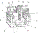
FIG. 1 is a schematic structural diagram of the present invention.
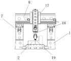
Fig. 2 is a front view of the present invention.
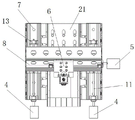
Fig. 3 is a side view of the present invention.
The reference numerals are respectively:
the milling head machining device comprises a base seat (1), a machining table (2), a milling head machining assembly (3), a horizontal driving mechanism (4), a vertical driving mechanism (5), a vertical driving mechanism (6), a Y-axis beam assembly (7), an X-axis beam assembly (8), a sliding block (9), a guide rail (10), a sliding rod (11), a sliding fixed block (12), a blocking block (13), a sliding boss (14), a parallel groove (15), a cooler (16), a machine tool ram (17), a machine tool spindle (18), a milling head (19), a water flow channel (20) and a water collecting box (21).
Detailed Description
In order to facilitate understanding of those skilled in the art, the present invention will be further described with reference to the following examples and drawings, which are not intended to limit the present invention. The present invention is described in detail below with reference to the attached drawings.
Example one
As shown in fig. 1-3, the three-axis numerical control machine tool provided by the invention comprises a base 1, a processing table 2, a milling head processing assembly 3, a horizontal driving mechanism 4, a vertical driving mechanism 5, a vertical driving mechanism 6 and a controller, wherein two ends of the upper end of the base 1 are symmetrically provided with a Y-axis beam assembly 7, the Y-axis beam assembly 7 is slidably mounted with an X-axis beam assembly 8, the X-axis beam assembly 8 is slidably provided with a sliding block 9, the milling head processing assembly 3 comprises a machine ram 17, a machine spindle 18 and a milling head 19, a guide rail 10 is arranged in the sliding block 9, the machine ram 17 is slidably mounted on the guide rail 10, the machine spindle 18 is mounted at the lower end of the machine ram 17, the milling head 19 is mounted at the lower end of the machine spindle 18, the horizontal driving mechanism 4 is used for driving the X-axis beam assembly 8 to move, the milling head 19 is more accurately machined by the aid of the horizontal driving mechanism 4, the vertical driving mechanism 5 and the vertical driving mechanism 6 in a negative feedback mode, and is reasonable in structural design and convenient to assemble.
In this embodiment, Y axle beam assembly 7 upper portion is provided with slide bar 11, X axle beam assembly 8 lower extreme be provided with slide bar 11 cooperation use the slip fixed block 12, slip fixed block 12 slidable mounting in on the slide bar 11, slide bar 11 both ends are provided with stop block 13, and slide bar 11 and the cooperation of slip fixed block 12 are used, can carry out further spacing along Y axle beam assembly 7 to X axle beam assembly 8, stop block 13 and can prevent that X axle beam assembly 8 excessively removes and break away from Y axle beam assembly 7.
In this embodiment, in order to prevent the sliding block 9 from separating from the X-axis beam assembly 8, a plurality of sliding bosses 14 arranged in parallel are disposed on the side of the X-axis beam assembly 8, and a plurality of parallel grooves 15 used in cooperation with the sliding bosses 14 are disposed on the sliding block 9.
In this embodiment, the milling head machining assembly 3 further includes a cooler 16, a water outlet of the cooler 16 is aligned with the milling head 19, the machining table 2 is provided with a plurality of water flow channels 20, a water collection box 21 is disposed on a side portion of the water flow channels 20, the cooler 16 can rapidly dissipate heat generated during machining of the milling head 19, and the water flow channels 20 and the water collection box 21 are used for cooling water sprayed from the mobile phone cooler 16.
In this embodiment, the machine tool spindle 18 is installed on a micrometer, the micrometer is electrically connected with the controller, and the micrometer is used for measuring the data of the rotation of the machine tool spindle 18 and sending the data to the controller for analysis and processing.
In this embodiment, the horizontal driving mechanism 4, the vertical driving mechanism 5, and the vertical driving mechanism 6 are all servo motors.
Example two
A displacement sensor transmits collected data to a controller, the controller converts the data of X, Y, Z shaft displacement of the three-shaft numerical control machine tool and compares the data with actual displacement, and the reading of a micrometer is transmitted to the controller;
according to the XY coordinate values of the point 1, the point 2 and the point 3 measured by the displacement sensor and the dial indicator reading of the Z axis:
according to the equation

It can be found that:

after the matrix is obtained, Δ X, Δ Y, and Δ Z are obtained and added to the controller, so that the controller controls the corresponding horizontal driving mechanism 4, vertical driving mechanism 5, and vertical driving mechanism 6.
In this embodiment, the controller is a PLC control system.
Although the present invention has been described with reference to the above preferred embodiments, it should be understood that various changes, substitutions and alterations can be made herein without departing from the spirit and scope of the invention as defined by the appended claims.
Claims (9)
1. A three-axis numerical control machine tool is characterized in that: including base, processing platform, cutter head processing subassembly, horizontal drive mechanism, vertical drive mechanism and controller, base upper end both ends symmetry is provided with Y axle beam assembly, Y axle beam assembly slidable mounting has X axle beam assembly, it is provided with the sliding block to slide on the X axle beam assembly, the cutter head processing subassembly includes lathe ram, lathe main shaft, cutter head, be provided with the guide rail in the sliding block, lathe ram slidable mounting in on the guide rail, the lathe main shaft install in the lathe ram lower extreme, the cutter head install in lathe main shaft lower extreme, horizontal drive mechanism is used for the drive X axle beam assembly removes, vertical drive mechanism is used for driving the sliding block and removes, vertical drive mechanism is used for the drive the lathe ram removes, horizontal drive mechanism vertical drive mechanism, Displacement sensors are installed on the vertical driving mechanisms, and the horizontal driving mechanism, the vertical driving mechanism and the displacement sensors are electrically connected with the controller.
2. The three-axis numerically controlled machine tool according to claim 1, wherein: y axle beam assembly upper portion is provided with the slide bar, X axle beam assembly lower extreme be provided with the slide bar cooperation is used the slip fixed block, slip fixed block slidable mounting in on the slide bar, the slide bar both ends are provided with and block the piece.
3. The three-axis numerically controlled machine tool according to claim 1, wherein: the X-axis beam assembly side part is provided with a plurality of parallel sliding bosses, and the sliding block is provided with a plurality of parallel grooves matched with the sliding bosses for use.
4. The three-axis numerically controlled machine tool according to claim 1, wherein: the milling head machining assembly further comprises a cooler, and a water outlet of the cooler is aligned with the milling head.
5. The three-axis numerically controlled machine tool according to claim 1, wherein: the machine tool spindle is arranged on a micrometer, and the micrometer is electrically connected with the controller.
6. The three-axis numerically controlled machine tool according to claim 1, wherein: the processing table is provided with a plurality of water flow channels, and the side parts of the water flow channels are provided with water collecting boxes.
7. The three-axis numerically controlled machine tool according to claim 1, wherein: the horizontal driving mechanism, the vertical driving mechanism and the vertical driving mechanism are all servo motors.
8. An error compensation method of a three-axis numerical control machine tool is characterized by comprising the following steps: the displacement sensor transmits the acquired data to the controller, the controller converts the displacement of the X, Y, Z shaft of the three-shaft numerical control machine tool and compares the data with the actual displacement, and the reading of the micrometer is transmitted to the controller;
according to the XY coordinate values of the point 1, the point 2 and the point 3 measured by the displacement sensor and the dial indicator reading of the Z axis:
according to the equation

It can be found that:

after the matrix is obtained, Δ X, Δ Y, and Δ Z are obtained and added to the controller, so that the controller controls the corresponding horizontal driving mechanism, vertical driving mechanism, and vertical driving mechanism.
9. The error compensation method of the three-axis numerical control machine tool according to claim 8, wherein: the controller is a PLC control system.
Priority Applications (1)
| Application Number | Priority Date | Filing Date | Title |
|---|---|---|---|
| CN202011487681.0A CN112676915A (en) | 2020-12-16 | 2020-12-16 | Three-axis numerical control machine tool and error compensation method thereof |
Applications Claiming Priority (1)
| Application Number | Priority Date | Filing Date | Title |
|---|---|---|---|
| CN202011487681.0A CN112676915A (en) | 2020-12-16 | 2020-12-16 | Three-axis numerical control machine tool and error compensation method thereof |
Publications (1)
| Publication Number | Publication Date |
|---|---|
| CN112676915A true CN112676915A (en) | 2021-04-20 |
Family
ID=75448388
Family Applications (1)
| Application Number | Title | Priority Date | Filing Date |
|---|---|---|---|
| CN202011487681.0A Pending CN112676915A (en) | 2020-12-16 | 2020-12-16 | Three-axis numerical control machine tool and error compensation method thereof |
Country Status (1)
| Country | Link |
|---|---|
| CN (1) | CN112676915A (en) |
Cited By (2)
| Publication number | Priority date | Publication date | Assignee | Title |
|---|---|---|---|---|
| CN113334138A (en) * | 2021-07-28 | 2021-09-03 | 安徽津野数控科技有限公司 | Automatic change triaxial digit control machine tool |
| CN118287734A (en) * | 2024-06-04 | 2024-07-05 | 济南盛世阳光机械零部件有限公司 | Milling head for numerical control machine tool and numerical control machine tool |
Citations (6)
| Publication number | Priority date | Publication date | Assignee | Title |
|---|---|---|---|---|
| CN201192776Y (en) * | 2008-05-08 | 2009-02-11 | 南京四开电子企业有限公司 | Planer-type numerically controlling engraving and milling machine |
| US20100024206A1 (en) * | 2006-12-26 | 2010-02-04 | Mitsubishi Heavy Industries, Ltd. | Spindle inclination detector and machine tool including the same |
| CN207037447U (en) * | 2017-07-04 | 2018-02-23 | 广东创能精密机械有限公司 | CNC machine tools capable of error compensation |
| CN207155252U (en) * | 2017-11-23 | 2018-03-30 | 山东科技大学 | A kind of three axle linear drives Digit Control Machine Tools of high accuracy |
| CN111496305A (en) * | 2020-04-30 | 2020-08-07 | 宁波市凯博数控机械有限公司 | Overhead efficient five-axis numerical control milling machine |
| CN111618612A (en) * | 2020-06-04 | 2020-09-04 | 飞创直线模组(苏州)有限公司 | Three-axis machine tool and control method thereof |
-
2020
- 2020-12-16 CN CN202011487681.0A patent/CN112676915A/en active Pending
Patent Citations (6)
| Publication number | Priority date | Publication date | Assignee | Title |
|---|---|---|---|---|
| US20100024206A1 (en) * | 2006-12-26 | 2010-02-04 | Mitsubishi Heavy Industries, Ltd. | Spindle inclination detector and machine tool including the same |
| CN201192776Y (en) * | 2008-05-08 | 2009-02-11 | 南京四开电子企业有限公司 | Planer-type numerically controlling engraving and milling machine |
| CN207037447U (en) * | 2017-07-04 | 2018-02-23 | 广东创能精密机械有限公司 | CNC machine tools capable of error compensation |
| CN207155252U (en) * | 2017-11-23 | 2018-03-30 | 山东科技大学 | A kind of three axle linear drives Digit Control Machine Tools of high accuracy |
| CN111496305A (en) * | 2020-04-30 | 2020-08-07 | 宁波市凯博数控机械有限公司 | Overhead efficient five-axis numerical control milling machine |
| CN111618612A (en) * | 2020-06-04 | 2020-09-04 | 飞创直线模组(苏州)有限公司 | Three-axis machine tool and control method thereof |
Cited By (3)
| Publication number | Priority date | Publication date | Assignee | Title |
|---|---|---|---|---|
| CN113334138A (en) * | 2021-07-28 | 2021-09-03 | 安徽津野数控科技有限公司 | Automatic change triaxial digit control machine tool |
| CN118287734A (en) * | 2024-06-04 | 2024-07-05 | 济南盛世阳光机械零部件有限公司 | Milling head for numerical control machine tool and numerical control machine tool |
| CN118287734B (en) * | 2024-06-04 | 2024-11-08 | 济南盛世阳光机械零部件有限公司 | Milling head for numerical control machine tool and numerical control machine tool |
Similar Documents
| Publication | Publication Date | Title |
|---|---|---|
| CN110548908B (en) | Gantry type coarse-fine composite five-axis precision machine tool and machining method | |
| CN102689263B (en) | Symmetric abrasive machining center with multiple carriages and double main shafts | |
| CN203875884U (en) | Five-axis manipulator | |
| CN210677068U (en) | A gantry type rough-finish compound five-axis precision machine tool | |
| CN103084854B (en) | A kind of numerical control machine tool and rotary table thereof | |
| CN112676915A (en) | Three-axis numerical control machine tool and error compensation method thereof | |
| CN102886648B (en) | Method and fixture for machining railway vehicle roof locking device | |
| CN116852050A (en) | Five-axis full-direct-drive bridge type gantry machining center and process for machining unmanned aerial vehicle rotary blades | |
| CN202951908U (en) | Six-station milling machine | |
| CN102183187B (en) | Method for assembling and positioning large-size machine tool body | |
| CN109227151B (en) | Multi-head efficient machining center | |
| CN1559754A (en) | Laser processing center for machining mould | |
| CN107543511A (en) | The flatness detecting system and its method of a kind of PCB equipment workbench | |
| CN212217764U (en) | Numerical control movable beam type five-axis gantry machining center machine tool | |
| CN111618612A (en) | Three-axis machine tool and control method thereof | |
| CN218658089U (en) | Modular numerical control machine tool | |
| CN218503852U (en) | Numerical control milling machine | |
| CN208214508U (en) | High-precision spiral case making lathe and its Measurement and Control System with on-line checking mechanism | |
| CN213794424U (en) | Filter plate processing production line | |
| CN218137036U (en) | Machine tool for grinding multiple grooves on linear shaft | |
| CN115770915A (en) | A gantry machining unit of an electric discharge machine tool | |
| CN115945965A (en) | A method and system for testing and analyzing thermal characteristics of a machine tool workbench | |
| CN214685577U (en) | Carving that carries high accuracy linear displacement sensor mills machine | |
| CN202922201U (en) | Spindle ram-combined guide rail unit for numerically controlled milling planers | |
| CN220613257U (en) | Shaft thermal elongation compensation device |
Legal Events
| Date | Code | Title | Description |
|---|---|---|---|
| PB01 | Publication | ||
| PB01 | Publication | ||
| SE01 | Entry into force of request for substantive examination | ||
| SE01 | Entry into force of request for substantive examination | ||
| RJ01 | Rejection of invention patent application after publication |
Application publication date: 20210420 |
|
| RJ01 | Rejection of invention patent application after publication |