EP2098328A2 - Workpiece support device and rotary indexer - Google Patents
Workpiece support device and rotary indexer Download PDFInfo
- Publication number
- EP2098328A2 EP2098328A2 EP20090002705 EP09002705A EP2098328A2 EP 2098328 A2 EP2098328 A2 EP 2098328A2 EP 20090002705 EP20090002705 EP 20090002705 EP 09002705 A EP09002705 A EP 09002705A EP 2098328 A2 EP2098328 A2 EP 2098328A2
- Authority
- EP
- European Patent Office
- Prior art keywords
- workpiece
- support shaft
- support
- countershaft
- frame
- Prior art date
- Legal status (The legal status is an assumption and is not a legal conclusion. Google has not performed a legal analysis and makes no representation as to the accuracy of the status listed.)
- Withdrawn
Links
- 238000003825 pressing Methods 0.000 claims abstract description 42
- 230000008878 coupling Effects 0.000 claims abstract description 40
- 238000010168 coupling process Methods 0.000 claims abstract description 40
- 238000005859 coupling reaction Methods 0.000 claims abstract description 40
- 230000002093 peripheral effect Effects 0.000 claims description 121
- 238000005096 rolling process Methods 0.000 claims description 22
- 238000003754 machining Methods 0.000 description 107
- 239000012530 fluid Substances 0.000 description 85
- 210000000078 claw Anatomy 0.000 description 45
- 230000004048 modification Effects 0.000 description 30
- 238000012986 modification Methods 0.000 description 30
- 230000033001 locomotion Effects 0.000 description 29
- 238000001514 detection method Methods 0.000 description 25
- 230000004044 response Effects 0.000 description 22
- 230000004913 activation Effects 0.000 description 19
- 230000009849 deactivation Effects 0.000 description 17
- 230000007246 mechanism Effects 0.000 description 15
- 230000007423 decrease Effects 0.000 description 8
- 238000006243 chemical reaction Methods 0.000 description 7
- 230000005764 inhibitory process Effects 0.000 description 6
- 230000036316 preload Effects 0.000 description 6
- 230000005540 biological transmission Effects 0.000 description 5
- 230000000149 penetrating effect Effects 0.000 description 5
- 239000000126 substance Substances 0.000 description 5
- 238000006073 displacement reaction Methods 0.000 description 4
- 238000000034 method Methods 0.000 description 4
- 230000009467 reduction Effects 0.000 description 4
- 239000002184 metal Substances 0.000 description 3
- 229910052751 metal Inorganic materials 0.000 description 3
- 230000003213 activating effect Effects 0.000 description 2
- 239000002173 cutting fluid Substances 0.000 description 2
- 230000005484 gravity Effects 0.000 description 2
- 238000003780 insertion Methods 0.000 description 2
- 230000037431 insertion Effects 0.000 description 2
- 238000009434 installation Methods 0.000 description 2
- 230000004397 blinking Effects 0.000 description 1
- 230000008859 change Effects 0.000 description 1
- 230000006835 compression Effects 0.000 description 1
- 238000007906 compression Methods 0.000 description 1
- 238000005520 cutting process Methods 0.000 description 1
- 239000004519 grease Substances 0.000 description 1
- 230000002401 inhibitory effect Effects 0.000 description 1
- 239000000314 lubricant Substances 0.000 description 1
- 125000006850 spacer group Chemical group 0.000 description 1
- 230000003746 surface roughness Effects 0.000 description 1
Images




Classifications
-
- B—PERFORMING OPERATIONS; TRANSPORTING
- B23—MACHINE TOOLS; METAL-WORKING NOT OTHERWISE PROVIDED FOR
- B23Q—DETAILS, COMPONENTS, OR ACCESSORIES FOR MACHINE TOOLS, e.g. ARRANGEMENTS FOR COPYING OR CONTROLLING; MACHINE TOOLS IN GENERAL CHARACTERISED BY THE CONSTRUCTION OF PARTICULAR DETAILS OR COMPONENTS; COMBINATIONS OR ASSOCIATIONS OF METAL-WORKING MACHINES, NOT DIRECTED TO A PARTICULAR RESULT
- B23Q1/00—Members which are comprised in the general build-up of a form of machine, particularly relatively large fixed members
- B23Q1/25—Movable or adjustable work or tool supports
- B23Q1/26—Movable or adjustable work or tool supports characterised by constructional features relating to the co-operation of relatively movable members; Means for preventing relative movement of such members
- B23Q1/28—Means for securing sliding members in any desired position
- B23Q1/287—Means for securing sliding members in any desired position using a hydraulically controlled membrane acting directly upon a sliding member
-
- B—PERFORMING OPERATIONS; TRANSPORTING
- B23—MACHINE TOOLS; METAL-WORKING NOT OTHERWISE PROVIDED FOR
- B23B—TURNING; BORING
- B23B23/00—Tailstocks; Centres
-
- B—PERFORMING OPERATIONS; TRANSPORTING
- B23—MACHINE TOOLS; METAL-WORKING NOT OTHERWISE PROVIDED FOR
- B23B—TURNING; BORING
- B23B31/00—Chucks; Expansion mandrels; Adaptations thereof for remote control
- B23B31/02—Chucks
- B23B31/10—Chucks characterised by the retaining or gripping devices or their immediate operating means
- B23B31/12—Chucks with simultaneously-acting jaws, whether or not also individually adjustable
- B23B31/16—Chucks with simultaneously-acting jaws, whether or not also individually adjustable moving radially
- B23B31/16195—Jaws movement actuated by levers moved by a coaxial control rod
- B23B31/16216—Jaws movement actuated by levers moved by a coaxial control rod using fluid-pressure means to actuate the gripping means
- B23B31/1622—Jaws movement actuated by levers moved by a coaxial control rod using fluid-pressure means to actuate the gripping means using mechanical transmission through the spindle
-
- B—PERFORMING OPERATIONS; TRANSPORTING
- B23—MACHINE TOOLS; METAL-WORKING NOT OTHERWISE PROVIDED FOR
- B23Q—DETAILS, COMPONENTS, OR ACCESSORIES FOR MACHINE TOOLS, e.g. ARRANGEMENTS FOR COPYING OR CONTROLLING; MACHINE TOOLS IN GENERAL CHARACTERISED BY THE CONSTRUCTION OF PARTICULAR DETAILS OR COMPONENTS; COMBINATIONS OR ASSOCIATIONS OF METAL-WORKING MACHINES, NOT DIRECTED TO A PARTICULAR RESULT
- B23Q16/00—Equipment for precise positioning of tool or work into particular locations not otherwise provided for
- B23Q16/02—Indexing equipment
- B23Q16/08—Indexing equipment having means for clamping the relatively movable parts together in the indexed position
- B23Q16/10—Rotary indexing
- B23Q16/102—Rotary indexing with a continuous drive
-
- B—PERFORMING OPERATIONS; TRANSPORTING
- B23—MACHINE TOOLS; METAL-WORKING NOT OTHERWISE PROVIDED FOR
- B23Q—DETAILS, COMPONENTS, OR ACCESSORIES FOR MACHINE TOOLS, e.g. ARRANGEMENTS FOR COPYING OR CONTROLLING; MACHINE TOOLS IN GENERAL CHARACTERISED BY THE CONSTRUCTION OF PARTICULAR DETAILS OR COMPONENTS; COMBINATIONS OR ASSOCIATIONS OF METAL-WORKING MACHINES, NOT DIRECTED TO A PARTICULAR RESULT
- B23Q16/00—Equipment for precise positioning of tool or work into particular locations not otherwise provided for
- B23Q16/02—Indexing equipment
- B23Q16/08—Indexing equipment having means for clamping the relatively movable parts together in the indexed position
- B23Q16/10—Rotary indexing
- B23Q16/107—Rotary indexing clamping with a drum brake
Definitions
- the present invention relates to a workpiece support device, the support device supporting a second end of the workpiece while a first end of the workpiece is coupled to a rotary shaft of a rotary drive.
- the present invention also relates to a rotary indexer including the workpiece support device, an indexing device serving as the rotary drive provided at a position opposite to the position of the support device, and a control device.
- the above-described rotary drive arranged at the position opposite to the position of the workpiece support device may be an indexing device mounted on a machine tool, or a spindle head of a machine tool such as a lathe.
- the indexing device provided at the position opposite to the position of the workpiece support device may be an indexing device mounted on a machine tool, or a spindle head of a machine tool such as a combined lathe having an indexing function.
- the workpiece support device may be a tailstock arranged at a position opposite to the position of a lathe headstock that holds a first end surface of a workpiece.
- a frame supports a tailstock sleeve in which a tailstock shaft is rotatably supported at the central axis of the tailstock sleeve.
- a play in the radial direction is provided between the frame and the tailstock sleeve.
- the tailstock sleeve is reciprocated by a hydraulic cylinder.
- a tailstock center coaxially provided at a tip of the tailstock shaft is pressed against a center bore at a second end surface of the workpiece.
- a play in the axial direction of a rotary shaft of the lathe headstock, the tailstock shaft, and the tailstock sleeve is eliminated by the pressed workpiece.
- a load exerted by a tool that is, a machining force by the tool is applied, and hence the workpiece is machined.
- the play in the axial direction of the rotary shaft of the headstock, the tailstock shaft, and the tailstock sleeve is eliminated by the pressed workpiece, the play in a radial direction provided between the frame and the tailstock sleeve is not eliminated.
- the tailstock center supported by the tailstock sleeve via the tailstock shaft is movable in a radial direction relative to the frame.
- the tailstock center and a second end of the workpiece are restricted from relatively moving in the axial direction, but not sufficiently restricted from moving in the radial direction, by a pressing force applied by the tailstock center to the center bore.
- the workpiece may be moved in the radial direction and vibrated, bent, or twisted, by the machining force applied by the tool in a direction intersecting with a plane containing the axis of the tailstock shaft, for example, a direction orthogonal to the plane.
- the workpiece is machined while being vibrated or deformed. This may deteriorate machining accuracy. When turning is carried out, rotation deflection occurs. This may deteriorate surface roughness in addition to the machining accuracy.
- An object of the present invention is to improve machining accuracy of a workpiece while a first end of the workpiece is coupled to a rotary shaft of a rotary drive.
- a workpiece support device is configured to support a second end of a workpiece while a first end of the workpiece is coupled to a rotary shaft of a rotary drive.
- the support device includes a coupling member configured to couple the second end of the workpiece; a support shaft, the coupling member provided at a first end of the support shaft; a frame configured to support the support shaft movably in an axial direction and rotatably; a force generating device configured to apply a force in the axial direction to the support shaft; and an axial clamping device including a single pressing member extending along the entire periphery of the support shaft or a plurality of pressing members equally arranged in a circumferential direction of the support shaft, the pressing member generating a force in a radial direction while the force generating device is activated, the axial clamping device fixing the support shaft to the frame in the axial direction by the force.
- the second end of the workpiece is coupled to the support shaft via the coupling member while the first end of the workpiece is coupled to the rotary shaft of the rotary drive, and the axial clamping device is activated to fix the support shaft in the axial direction while the force generating device presses or draws the second end of the workpiece via the support shaft and the coupling member. Accordingly, a play in the axial direction between the support shaft and the rotary shaft is eliminated by the workpiece, that is, a reaction force from the workpiece. Also, while the force generating device is activated, the axial clamping device is activated and the force in the radial direction is equally applied to the periphery of the support shaft.
- the support shaft is continuously coaxial with the rotary shaft.
- the rotary shaft, the workpiece, and the support shaft are integrated while the rotary shaft is continuously coaxial with the support shaft.
- the workpiece is supported by the rotary shaft and the support shaft with the play eliminated in the axial direction and the radial direction.
- the workpiece is machined without being moved or vibrated by a load in the axial direction applied from a tool, i.e., a machining force in the axial direction.
- the workpiece is machined while a coaxial state is maintained without being vibrated or deformed in the radial direction by a load in the radial direction applied from the tool, i.e., a machining force in the radial direction. Therefore, the workpiece can be machined with high accuracy.
- the support shaft may be directly supported by the frame.
- the workpiece support device further includes a countershaft provided at the outside in the radial direction of the support shaft coaxially with the support shaft.
- the frame supports the support shaft movably in the axial direction and rotatably in association with the countershaft.
- One of pairs including a pair of the support shaft and the countershaft and a pair of the countershaft and the frame is configured to be relatively rotatable but not relatively movable in the axial direction via a rolling bearing.
- the pressing member of the axial clamping device is supported by an outer member in the radial direction of the other one of the pairs, the axial clamping device applying a pressing force as a force in the radial direction to the outer peripheral surface of an inner member in the radial direction of the other one of the pairs.
- the frame and the countershaft support the support shaft movably in the axial direction and rotatably in association with each other. Accordingly, the support shaft is rotatable even when the axial clamping device is activated and movement in the axial drection of the support shaft is resticted.
- the workpiece is rotatable while movement in the axial direction and movement in the radial direction at the second end of the workpiece are restricted. Accordingly, rotational machining of the workpiece (turning machining, indexing machining in correspondence with a phase angle of the workpiece during continous rotation) can be carried out with high accuracy.
- the support shaft does not have to be actively held not rotatably.
- the support device further includes a rotational clamping device configured to restrict relative rotation of the one of the pairs.
- the rotational clamping device by activating the rotational clamping device in addition to the axial clamping device, the movement in the axial direction and the rotation of the supoprt shaft are restricted.
- the workpiece is prevented from being rotated at the second end of the workpiece, i.e., from being twisted by a machining force in a direction intersecting with a plane containing the axis, for example, in a direction orthogonal to the plane containing the axis, which is a machining force applied at a position deviated from the axis in the direction intersecting with the plane. Accordingly, the workpiece is machined without being deformed, thereby improving the machining accuracy.
- the first end of the workpiece may be coupled to the rotary shaft of the rotary drive without an indexing function.
- the first end of the workpiece W may be coupled to a rotary shaft of an indexing device so that the workpiece support device forms a rotary indexer.
- a rotary indexer according to a second aspect of the present invention which includes the workpiece support device of the first aspect; an indexing device serving as the rotary drive provided at a position opposite to the position of the support device and including the rotary shaft to which the first end of the workpiece is coupled; and a control device.
- the control device deactivates the rotational clamping device when the indexing device is rotated, and activates the rotational clamping device when the rotation of the indexing device is stopped.
- the control device deactivates the rotational clamping device when the indexing device is rotated. Accordingly, correct rotational indexing and highly accurate turning machining of the workpiece can be carried out. Also, the control device activates the rotational clamping device when the rotation of the indexing device is stopped. Accordingly, the support shaft is restricted from moving in the axial direction and from rotating.
- the workpiece is machined without being moved and vibrated in the axial direction by a machining force and wihtout being rotated and twisted at the second end of the workpiece by the machining force. Hence, the workpiece is machined without being deformed, thereby improving the machining accuracy.
- a rotary indexer according to a third aspect of the invention which includes the workpiece support device of the first aspect; an indexing device serving as the rotary drive provided at a position opposite to the position of the support device and including the rotary shaft to which the first end of the workpiece is coupled; and a control device.
- the pressing member of the axial clamping device is supported by the frame and applies a pressing force as the force in the radial direction to the outer peripheral surface of the support shaft, and the support device fixes the support shaft to the frame not movably in the axial direction and not rotatably relative to the frame by the pressing force.
- the control device deactivates the axial clamping device and activates the force generating device when the indexing device is rotated, and activates the axial clamping device while the force generating device is activated when the rotation of the indexing device is stopped.
- control device deactivates the axial clamping device and activates the force generating device when the indexing device is rotated, the support shaft and the rotary shaft are rotated while the play in the axial direction is continuously eliminated. Accordingly, correct rotational indexing and highly accurate turning machining of the workpiece can be carried out. Also, since the control device activates the axial clamping device while the force generating device is activated when the rotation of the indexing device is stopped, movement in the axial direction, vibration, and rotation of the support shaft are restricted while the support shaft is coaxial with the frame.
- the rotary indexer only the indexing device that supports the first end of the workpiece may carry out indexing for the workpiece, and the support shaft of the support device may be rotated via the workpiece.
- the following configuration is preferable.
- the rotary indexer further includes a drive configured to cause the support shaft to be rotated in the same manner as the indexing device.
- both ends of the workpiece can be rotationally driven by the indexing device and the support device.
- the workpiece is rotated without being twisted. Accordingly, machining accuracy and indexing accuracy for indexing machining are improved. Also, machining accuracy for rotational machining is improved.
- the drive may cause the support shaft to be rotated in the same manner as the indexing device via a transmission mechanism, while a driving motor of the indexing device serves as a common drive source.
- the drive includes a dedicated driving motor which is different from a driving motor of the indexing device.
- the drive includes a control device configured to drive the dedicated driving motor synchronously with the driving motor of the indexing device.
- the drive includes the dedicated driving motor which is different from the driving motor of the indexing device.
- the control device of the drive drives the dedicated driving motor synchronously with the driving motor of the indexing device.
- the drive does not include a transmission mechanism coupled to the driving motor of the indexing device. Accordingly, the drive can be simplified. Also, synchronization deviation between the support shaft and the rotary shaft due to the use of the above transmission mechanism does not occur. In particular, synchronization deviation between the support shaft and the rotary shaft does not occur, the deviation may be caused by a play or twisting of a transmission mechanism component such as a gear, a timing pulley, a timing belt, a coupling, and a shaft.
- a transmission mechanism component such as a gear, a timing pulley, a timing belt, a coupling, and a shaft.
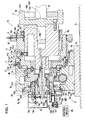
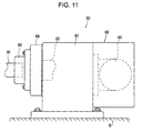
- a rotary indexer 50 includes an indexing device 60 ( Fig. 11 ) serving as a rotary drive, a workpiece support device 70 ( Figs. 1 , 4 , 7 , and 8 ) arranged at a position opposite to the position of the indexing device 60, and a control device 80 for both devices 60 and 70.
- the control device 80 controls the support device 70 in accordance with the operation of the indexing device 60.
- the indexing device 60 holds a first end of the workpiece W and the workpiece support device 70 holds a second end of the workpiece W.
- the indexing device 60 is mounted on a bed B of a machine tool.
- the machine tool includes a rotary shaft of a tool such as a grindstone, an end mill, a drill, a tap, etc., or a holder of a tool such as a cutting tool, and the tool is driven by, for example, numerical control.
- the indexing device 60 may serve as a workpiece supporting part, such as a headstock of a combined lathe having an indexing function, and define a machine tool with a tool driving part.
- the indexing device 60 includes a body 61 mounted on and fixed to the bed B; a rotary shaft 62 rotatably supported in the body 61; a driving motor 63; a rotation transmission mechanism (not shown) provided in the body 61, having a worm speed reduction device or the like, and transmitting a torque of the driving motor 63 to the rotary shaft 62; a rotary table 64 provided at a first end of the rotary shaft 62, the rotary table 64 rotating for indexing; and a workpiece mounting jig 65 detachably attached to a workpiece mounting surface of the rotary table 64 by a bolt or the like, the workpiece mounting jig 65 fixing a first end of the workpiece W.
- the workpiece support device 70 includes a frame 1 mounted on and fixed to the bed B; a countershaft 4 fitted to the inner peripheral surface of the frame 1; and a support shaft 2 fitted to the inner peripheral surface of the countershaft 4 and supported by the countershaft 4 movably in the axial direction and rotatably relative to the frame 1 via the countershaft 4.
- the frame 1 specifically, the inner peripheral surface of the frame 1, to which the countershaft 4 is fitted, is coaxial with the countershaft 4 and the support shaft 2.
- the workpiece support device 70 includes a coupling member 3 provided at a first end of the support shaft 2 so as to couple the second end of the workpiece W; a force generating device 5 that applies a force in the axial direction to the support shaft 2; an axial clamping device 6 that restricts the support shaft 2 from moving in the axial direction; a rotational clamping device 7 that restricts the support shaft 2 from rotating by restricting relative rotation of the frame 1 and the countershaft 4; and a drive 8 that rotates the support shaft 2.
- the frame 1 includes a base plate 1a and a frame body 1b fixed to the base plate 1a by a bolt.
- the base plate 1a moves on the bed B in the axial direction of the support shaft 2 along a guide groove (not shown) having, for example, a dovetail-groove shape, and is fixed to the bed B via a clamping member (not shown). Accordingly, the position of the support device 70 opposite to the position of the indexing device 60 is adjusted in the axial direction depending on the length of the workpiece W.
- the frame body 1b has a plurality of hollow first to fifth frame members 1b1 to 1b5 which are fastened by bolts to be integrated.
- the frame members 1b1 to 1b5, excluding a part of the frame member 1b1, define a cylindrical body.
- the frame body 1b serves as a housing space of the countershaft 4.
- the diameter of the outer peripheral surface of the countershaft 4 gradually increases in the axial direction toward the workpiece W.
- the diameter of the inner peripheral surface of the frame body 1b increases to correspond to the countershaft 4.
- the frame body 1b includes the first frame member 1b1 fixed to the base plate 1a; the second frame member 1b2 having a disk-like shape and fixed to a not-workpiece-side end surface of the first frame member 1b1; the third frame member 1b3 fitted to a not-workpiece-side inner peripheral surface portion of the first frame member 1b1 and having a flange part which is pressed via a bolt and a washer and fixed to the first frame member 1b1; the fourth frame member 1b4 fitted to the inner peripheral surface of the third frame member 1b3 and fixed to the first frame member 1b1 via the second frame member 1b2; and the fifth frame member 1b5 serving as a fixing member to fix the outer ring of a cross roller bearing serving as a rolling bearing 9, the fifth frame member 1b5 fitted to a bearing-outer-ring fitting surface of the first frame member 1b1.
- the countershaft 4 which is a hollow cylinder, is provided at the inside in the radial direction of the frame 1 coaxially with the inner peripheral surface of the frame 1 to which the countershaft 4 is fitted.
- the countershaft 4 houses the support shaft 2.
- the countershaft 4 has a plurality of first to third countershaft members 4a to 4c which are fixed by bolts to be integrated. By fitting the plurality of countershaft members 4a to 4c to each other, the countershaft members 4a to 4c having the coaxially formed peripheral surfaces, all peripheral surfaces of the countershaft members 4a to 4c are formed coaxially with the frame 1, in particular, with a countershaft fitting surface of the frame 1 and the support shaft 2.
- first to third countershaft members 4a to 4c of the countershaft 4 are arranged from the not-workpiece side toward the workpiece side in that order.
- the first countershaft member 4a is fitted to the inner peripheral surface of the fourth frame member 1b4.
- the third countershaft member 4c is fitted to a body member 7a of the rotational clamping device 7 (described later).
- the second countershaft member 4b is arranged between the first and third countershaft members 4a and 4c, and is fitted to the outer peripheral surfaces of the first and third countershaft members 4a and 4c.
- a worm wheel 8c and the inner ring of the rolling bearing 9 are fitted to the outer peripheral surface of the second countershaft member 4b.
- the support shaft 2 is formed such that the diameter of the outer peripheral surface of the support shaft 2 gradually increases from the not-workpiece side toward the workpiece side.
- the support shaft 2 includes a first support shaft member 2a located at the not-workpiece side and a second support shaft member 2b located at the workpiece side.
- the peripheral surfaces of both members 2a and 2b are fitted to each other and integrated by a bolt.
- the outer peripheral surface of the support shaft 2 is fitted to the inner peripheral surface of the countershaft 4 with a clearance, i.e., a play, provided therebetween.
- An oil film of, for example, a lubricant or grease is formed in the play, thereby allowing the support shaft 2 and the countershaft 4 to smoothly slide on each other.
- a center bore 2b1 is made at the central axis of a workpiece-side end surface of the second support shaft member 2b.
- the center bore 2b1 serves as a mounting reference hole for the coupling member 3 that couples the second end of the workpiece W.
- a block 2b2 is fitted to an intermediate part of the center bore 2b1 to serve as a lid, so as to prevent a foreign substance, such as cutting fluid, from entering the inside through an insertion hole of the bolt that fastens the support shaft members 2a and 2b.
- the coupling member 3 detachably couples the workpiece W to the support shaft 2 by a bolt, or claws configured to be advanced and retracted in the radial direction.
- a manual chucking device is used as the coupling member 3.
- the chucking device includes a base 3a and a plurality of claws 3b.
- the base 3a has a cylindrical shape with a bottom, to be open to the workpiece side.
- the plurality of claws 3b can be advanced in the radial direction from the inner peripheral surface of a cylindrical portion 3a1 of the base 3a by an advance/retract mechanism (not shown).
- a contact surface 3a3 that contacts the second end surface of the workpiece W protrudes at the central axis from a workpiece-side bottom surface of a bottom portion 3a2 of the base 3a.
- a mounting reference shaft portion protrudes at the central axis from a not-workpiece-side bottom surface of the bottom portion 3a2 of the base 3a.
- a dedicated handle wrench is attached to operate the advance/retract mechanism (not shown), so that the tip ends of the plurality of claws 3b are positioned at equal distances from the central axis to hold (or release) the workpiece W. Accordingly, the workpiece W is coaxially coupled to (or decoupled from) the support shaft 2.
- the axial clamping device 6 is provided at a workpiece-side end portion of the countershaft 4.
- the axial clamping device 6 includes a body member 6a having a flange part fixed to a workpiece-side end surface of the third countershaft member 4c by a bolt, a thin ring portion 6a1 formed at a cylindrical part of the body member 6a, a ring-shaped clamping pressure chamber 6b formed between the outer peripheral surface of the thin ring portion 6a1 and the inner peripheral surface of the third countershaft member 4c, a channel 6c penetrating through the third countershaft member 4c from the outer peripheral surface thereof in the radial direction and communicating with the clamping pressure chamber 6b, and a joint member 6d fitted to the outer peripheral surface of the third countershaft member 4c and fixed to the frame 1 via a bracket 6e.
- a rotary joint is defined to include the outer peripheral surface of the third countershaft member 4c and the inner peripheral surface of the joint member 6d.
- the channel 6c communicates with a high-pressure fluid supply (not shown) via the rotary joint, a connector terminal 6f provided at the outer peripheral surface of the joint member 6d, and a pipe.
- the thin ring portion 6a1 functions as a pressing member provided at the countershaft 4.
- the diameter of the thin ring portion 6a1 decreases by the fluid pressure of the high-pressure fluid of the clamping pressure chamber 6b.
- the thin ring portion 6a1 presses the outer peripheral surface of the support shaft 2, and restricts relative movement of the countershaft 4 and the support shaft 2. The thin ring portion 6a1 thusly restricts relative movement in the axial direction of the countershaft 4 and the support shaft 2.
- a single pressing member that is, the thin ring portion 6a1 has a ring shape and extends along the entire periphery of the support shaft 2 so as to equally press the outer peripheral surface of the support shaft 2. Accordingly, the play in the radial direction between the countershaft 4 and the support shaft 2 is equally eliminated at the entire periphery while the relative movement in the axial direction of the countershaft 4 and the support shaft 2 is restricted, thereby achieving the coaxial arrangement of the countershaft 4 and the support shaft 2.
- a plurality of pressing members may be equally arranged in a circumferential direction of the support shaft 2. Similarly to the above, the play in the radial direction between the countershaft 4 and the support shaft 2 is equally eliminated at the entire periphery, thereby achieving the coaxial arrangement of the countershaft 4 and the support shaft 2.
- a detent device 11 is provided.
- the device 11 restricts relative rotation of the countershaft 4 and the support shaft 2 and permits relative movement in the axial direction of the countershaft 4 and the support shaft 2.
- the detent device 11 includes a retaining groove 11a extending in the outer peripheral surface of the support shaft 2 in the axial direction, and a pin serving as a retaining member 11c.
- the retaining member 11c is fitted into a through hole 11b penetrating through the countershaft 4 from the outer peripheral surface in the radial direction and reaching the retaining groove 11a.
- the retaining member 11c is also fitted into the retaining groove 11a.
- the fitting surfaces of the retaining member 11c and the retaining groove 11a are defined by two flat surfaces parallel to each other.
- the retaining groove 11a extends by a length which is greater than a permissible relative movement distance of the countershaft 4 and the support shaft 2.
- a cap 11d is screwed into the through hole 11b so as to prevent the retaining member 11c from being removed and to prevent a foreign substance such as cutting fluid from entering the inside.
- An internal thread 11e is provided at a head portion of the retaining member 11c.
- a dedicated workpiece mounting jig is used as the coupling member 3 fixed to the support shaft 2 of the support device 70, instead of the chucking device of this embodiment.
- the permissible mounting phase of the workpiece W and the coupling member 3 is determined. Unless the relative phase of the second end of the workpiece W and the coupling member 3 is the permissible mounting phase, the second end of the workpiece W cannot be mounted to the coupling member 3 while the first end of the workpiece W is fixed to the indexing device 60.
- the coupling member 3 is manually rotated with hand while the axial clamping device 6 is deactivated by removing the retaining member 11c and deactivating the detent device 11, so that the relative phase of the coupling member 3 and the second end of the workpiece W is adjusted to the mounting phase without rotating the countershaft 4 by the drive 8 (described later).
- the rotational clamping device 7 is provided at a workpiece-side end portion of the frame 1.
- the rotational clamping device 7 includes a body member 7a having a flange part fixed to a workpiece-side end surface of the first frame member 1b1 by a bolt, a thin ring portion 7a1 formed at a cylindrical part of the body member 7a, a ring-shaped clamping pressure chamber 7b formed between the outer peripheral surface of the thin ring portion 7a1 and the inner peripheral surface of the first frame member 1b1, and a channel 7c penetrating through the first frame member 1b1 from the outer peripheral surface in the radial direction and communicating with the clamping pressure chamber 7b.
- the channel 7c communicates with a high-pressure fluid supply (not shown) via a connector terminal 7d provided at the outer peripheral surface of the first frame member 1b1, and a pipe.
- the thin ring portion 7a1 functions as a pressing member provided at the frame 1.
- the diameter of the thin ring portion 7a1 decreases by the fluid pressure of the high-pressure fluid of the clamping pressure chamber 7b.
- the thin ring portion 7a1 presses the outer peripheral surface of the countershaft 4, and restricts relative movement of the frame 1 and the countershaft 4. The thin ring portion 7a1 thusly restricts rotation of the countershaft 4.
- the rotational clamping device 7 When the rotational clamping device 7 is deactivated, the pressure of the high-pressure fluid is reduced. The diameter of the inner peripheral surface of the thin ring portion 7a1 returns to the original diameter. Hence, the thin ring portion 7a1 stops pressing the outer peripheral surface of the support shaft 2, and the support shaft 2 becomes rotatable.
- a single pressing member that is, the thin ring portion 7a1 extends along the entire periphery of the support shaft 2 so as to equally press the outer peripheral surface of the support shaft 2 in a similar manner to the axial clamping device 6.
- the rotational clamping device 7 differs from the axial clamping device 6 in that the pressing member may have a structure in which a pressing member unequally presses the outer peripheral surface of the support shaft 2, or a structure in which a pressing member supported by one of the frame 1 and the support shaft 2 moves in the axial direction and presses an end surface of the other of the frame 1 and the support shaft 2 so as to clamp the rotation of the support shaft 2.
- the outer ring of the rolling bearing 9 is fitted to the first frame member 1b1, and the inner ring thereof is fitted to the second countershaft member 4b of the countershaft 4.
- the outer ring is restricted from moving in the axial direction by a surface formed at a step portion of the first frame member 1b1 and being orthogonal to the axis of the first frame member 1b1, i.e., an orthogonal-to-axis step-portion surface of the first frame member 1b1, and by the fifth frame member 1b5.
- the inner ring is restricted from moving in the axial direction by an orthogonal-to-axis step-portion surface of the second countershaft member 4b, and by a spacer 21 which is arranged between the orthogonal-to-axis step-portion surface of the third countershaft member 4c and the inner ring and fitted to an inner ring fitting surface of the second countershaft member 4b.
- a roller serving as a rolling member permits relative rotation of the outer and inner rings but restricts relative movement in the axial direction of the outer and inner rings.
- Such structure may be applied to one of pairs including a pair of the support shaft 2 and the countershaft 4 and a pair of the countershaft 4 and the frame 1.
- the countershaft 4 and the frame 1 are configured to be relatively rotatable but not relatively movable in the axial direction via the rolling bearing 9.
- the rolling bearing 9 in this embodiment is a single cross roller bearing which receives a radial load, a thrust load applied from the workpiece side, and a thrust load applied from the not-workpiece side, and causes the countershaft 4 and the frame 1 to be relatively rotatable but not relatively movable in the axial direction.
- the rolling bearing 9 may be formed of a plurality of rolling bearing members including, for example, a radial bearing or a plurality of radial bearings at an interval in the axial direction, a thrust bearing which receives the thrust load applied from the workpiece side, and a thrust bearing which receives the thrust load applied from the not-workpiece side.
- the support shaft 2 is driven by the drive 8 synchronously with the rotary shaft 62 of the indexing device 60.
- the drive 8 includes a dedicated driving motor M (not shown) which is different from the driving motor 63 of the indexing device 60, a coupling (not shown), and a worm speed reduction mechanism 8a contained in the frame 1.
- the drive 8 rotationally drives the countershaft 4, thereby rotationally driving the support shaft 2 which is not rotatable relative to the countershaft 4.
- the worm speed reduction mechanism 8a includes a worm 8b supported by the frame 1 and coupled to the dedicated driving motor M via the coupling, and a worm wheel 8c fixed to the countershaft 4 and meshing with the worm 8b.
- the force generating device 5 also serves as a moving device of the support shaft 2 in the axial direction.
- the force generating device 5 includes a double-acting fluid-pressure cylinder device formed of the first countershaft member 4a of the countershaft 4 serving as a cylinder and the first support shaft member 2a of the support shaft 2 serving as a piston.
- An advance pressure chamber 5b1 is formed at the not-workpiece side and a retract pressure chamber 5c1 is formed at the workpiece side while a piston wall is arranged therebetween.
- a rotary joint is defined to include the inner peripheral surface of the fourth frame member 1b4 and the outer peripheral surface of the first countershaft member 4a.
- the advance pressure chamber 5b1 and the retract pressure chamber 5c1 are respectively communicate with connector terminals 5d and 5e provided at a not-workpiece-side end surface of the fourth frame member 1b4 via the rotary joint, and via an advance channel 5b and a retract channel 5c made in the fourth frame member 1b4 and the first countershaft member 4a.
- the advance pressure chamber 5b1 and the retract pressure chamber 5c1 are connected to the high-pressure fluid supply via a pipe, an electromagnetic on-off valve (not shown), and a regulator.
- a pipe an electromagnetic on-off valve (not shown), and a regulator.
- An axial position sensor 13 of the support shaft 2 is provided at the not-workpiece side of the support device 70.
- the axial position sensor 13 detects advance by a distance exceeding a permissible limit and a retract limit of the support shaft 2 which is advanced and retracted by the force generating device 5.
- the axial position sensor 13 includes a pair of sensors 13a and a ring-shaped detection object 13b.
- the pair of sensors 13a is fixed to an axially long hole of a sensor holder 13c fixed to the frame 1 such that the positions in the axial direction of the sensors 13a are adjustable.
- the detection object 13b is fixed to the support shaft 2 by a setscrew.
- the workpiece-side sensor 13a is used for error detection such as a coupling error of the workpiece W, and an installation error of the support device 70.
- This sensor 13a detects the detection object 13b, for example, when the support shaft 2 is advanced by a predetermined distance or greater, in particular, when the first end of the workpiece W is not correctly coupled to the rotary shaft 62 of the indexing device 60 and hence the contact surface 3a3 of the coupling member 3 is advanced by a predetermined distance or greater, or when the support device 70 is arranged at a predetermined distance or greater from the indexing device 60 and then the contact surface 3a3 of the coupling member 3 is advanced by a predetermined distance or greater.
- This sensor 13a outputs an error detection signal to a control device of the machine tool via the control device 80.
- the control device of the machine tool outputs an operation inhibition signal in response to the error detection signal.
- the not-workpiece side sensor 13a detects the retract limit of the support shaft 2.
- the sensor 13a detects the detection object 13b
- the sensor 13a outputs a retract completion signal to the control device of the machine tool via the control device 80.
- the control device of the machine tool stops the supply of the high-pressure fluid from the high-pressure fluid supply in response to the retract completion signal.
- Two ring-shaped spaces are formed by the outer peripheral surface of the support shaft 2 and the inner peripheral surface of the countershaft 4, and by two facing orthogonal-to-axis step-portion surfaces of the support shaft 2 and the countershaft 4, at a distance in the axial direction.
- the two ring-shaped spaces communicate with the outside air via an air vent 2b3 made in the support shaft 2 and being open to a not-workpiece-side end surface of the support shaft 2 so as to handle a change in volume thereof when the support shaft 2 is advanced and retracted.
- the axial clamping device 6 in this embodiment includes an operation check device 12 to prevent the workpiece W from being machined while the axial clamping device 6 is deactivated.
- the operation check device 12 is formed to include a channel 6g being open to the not-workpiece-side end surface of the fourth frame member 1b4, made in the fourth frame member 1b4 and the countershaft 4, and communicating with the clamping pressure chamber 6b; the inner peripheral surface of the fourth frame member 1b4; and the outer peripheral surface of the countershaft 4.
- the operation check device 12 includes a rotary joint, at which the channel 6g of the fourth frame member 1b4 communicates with the channel 6g of the countershaft 4; a single-acting cylinder provided with a return spring 12a; a detection object 12g fixed at a ram 12b of the single-acting cylinder; and a pair of sensors 12f.
- the operation check device 12 moves the ram 12b by using a fluid pressure actually added to the clamping pressure chamber 6b with the high-pressure fluid against an urging force of the return spring 12a.
- the state whether the axial clamping device 6 is actually activated or deactivated can be recognized.
- the single-acting cylinder includes a cylinder body 12e having a circulation hole 12h at a workpiece-side end surface thereof, the circulation hole 12h being connected to the channel 6g of the fourth frame member 1b4; a sleeve 12d provided at a not-workpiece-side end of the cylinder body 12e; the ram 12b fitted to the inner peripheral surface of the sleeve 12d; the return spring 12a surrounding the outer peripheral surface of the ram 12b; and a washer 12i fixed to a workpiece-side end surface of the ram 12b.
- the detection object 12g is inserted into the not-workpiece side of the ram 12b such that the position in the axial direction of the detection object 12g is adjusted.
- the detection object 12g is fixed by a setscrew.
- a sensor holder 12c is fixed to a not-workpiece-side end surface of the sleeve 12d.
- the pair of sensors 12f is provided at the sensor holder 12c, at a distance in the axial direction of the ram 12b.
- the figure illustrates the state in which the ram 12b is located at a workpiece-side limit position.
- the detection object 12g faces the workpiece-side sensor 12f.
- This sensor 12f outputs a deactivation recognition signal to the control device 80, and therefore, the control device 80 recognizes that no fluid pressure is applied to the clamping pressure chamber 6b.
- the control device 80 recognizes that the axial clamping device 6 is activated while a predetermined pressure is applied to the clamping pressure chamber 6b.
- control device 80 When the control device 80 does not receive the activation recognition signal from the not-workpiece-side sensor 12f although the control device 80 has output an activation command signal of the axial clamping device 6, a hydraulic motor, a high-pressure fluid supply such as an air compressor, a regulator, or an electromagnetic on/off valve may be in a fail. Then, the control device 80 outputs the operation inhibition signal to the control device of the machine tool, thereby inhibiting the workpiece W from being machined.
- a hydraulic motor, a high-pressure fluid supply such as an air compressor, a regulator, or an electromagnetic on/off valve
- the rotational clamping device 7 may have an operation check device in a similar manner to the axial clamping device 6.
- the control device 80 outputs the operation inhibition signal if the control device 80 does not receive the activation recognition signal from a sensor of the operation check device when an activation command of the rotational clamping device 7 is output, or if the control device 80 does not receive the deactivation recognition signal from the sensor of the operation check device when the deactivation command of the rotational clamping device 7 is output.
- the machining procedure of machining the workpiece W using the rotary indexer 50 is described below.
- the indexing device 60 and the support device 70 are arranged on the bed B of the machine tool at positions opposite to each other.
- the support device 70 is moved on the bed B and fixed at a predetermined distance from the indexing device 60 depending on the length of the workpiece W, whereas the support device 70 is fixed such that the support shaft 2 is located coaxially with the rotary shaft 62 of the indexing device 60.
- the control device 80 opens a supply valve and closes an exhaust valve at an advance electromagnetic on/off valve, and closes a supply valve and opens an exhaust valve at a retract electromagnetic on/off valve, in response to an activation signal of the force generating device 5 from the control device of the machine tool. Accordingly, the high-pressure fluid is supplied from the high-pressure fluid supply to the advance pressure chamber 5b1 with a predetermined pressure, and exhausted from the retract pressure chamber 5c1.
- the support shaft 2 is advanced, and the contact surface 3a3 of the chucking device contacts the second end surface of the workpiece W, thereby pressing the end surface by a force corresponding to the predetermined pressure of the high-pressure fluid.
- the play in the axial direction between the rotary shaft 62 of the indexing device 60 and the support shaft 2 of the support device 70 is eliminated by the workpiece W, in particular, by a reaction force applied by the workpiece W.
- the operator attaches the handle wrench to the chucking device to operate the advance/retract mechanism (not shown), thereby moving the plurality of claws 3b in the radial direction and holding the outer peripheral surface of the workpiece W. Accordingly, the second end of the workpiece W is fixed and coupled to the support shaft 2 via the chucking device.
- the operator operates a machining start switch provided on the operation panel of the machine tool.
- the control device 80 activates the axial clamping device 6 in response to a machining start signal input via the control device of the machine tool.
- the operator opens the supply valve of the electromagnetic on/off valve of the axial clamping device 6, so that the high-pressure fluid is supplied from the high-pressure fluid supply to the clamping pressure chamber 6b. Accordingly, the diameter of the thin ring portion 6a1 of the body member 6a decreases.
- the thin ring portion 6a1 equally presses the outer peripheral surface of the support shaft 2.
- the play in the radial direction between the countershaft 4 and the support shaft 2 is equally eliminated at the entire periphery.
- the countershaft 4 and the support shaft 2 are coaxially integrated.
- the support shaft 2 is continuously coaxial with the frame 1, in particular, with the inner peripheral surface of the frame 1 to which the countershaft 4 is fitted, via the countershaft 4 even after the axial clamping device 6 is operated.
- the control device of the machine tool outputs a predetermined index angle signal to the control device 80.
- the control device 80 synchronously rotates the driving motor 63 and the dedicated driving motor M in accordance with an index angle signal, and stops the driving motor 63 and the dedicated driving motor M at a predetermined rotation index angle. Accordingly, the rotary shaft 62 and the support shaft 2 which is not rotatable relative to the countershaft 4 are synchronously rotated.
- the workpiece W the first and second ends of which are respectively supported by the rotary shaft 62 and the support shaft 2 can be prevented from being twisted and deformed during indexing even when the workpiece W has a large weight and a large rotational resistance, even when the workpiece W is cut before machining or during machining and has a low torsion strength, or even when the center of gravity of the workpiece W is deviated from the axis and the torque due to the gravity varies depending on the rotational angle. Both ends of the workpiece W are stopped at the predetermined workpiece index angle, and the workpiece W can be held by the rotary indexer 50 without being twisted and deformed.
- the control device 80 activates a clamping device (not shown) of the indexing device 60 to clamp the rotary shaft 62 after the motors 63 and M are stopped. Also, the control device 80 opens the supply valve and closes the exhaust valve of the electromagnetic on/off valve of the rotational clamping device 7, so as to supply the high-pressure fluid from the high-pressure fluid supply to the clamping pressure chamber 7b. Accordingly, the rotational clamping device 7 is activated, and the relative rotation of the frame 1 and the countershaft 4 is restricted. Thus, the support shaft 2 becomes not movable relative to the frame 1 via the countershaft 4 while the support shaft 2 is coaxial with the frame 1.
- the support shaft 2 is not rotatable and not movable in the axial direction relative to the frame 1 via the countershaft 4.
- the workpiece W is integrally fixed to the frame 1, i.e., the workpiece W is held by the support device 70 not relatively movably.
- the workpiece W is machined by a tool of the machine tool while the first and second ends of the workpiece W are held by the indexing device 60 and the support device 70 not relatively movably.
- the workpiece W receives a machining force in a direction intersecting with the axial direction, such as a direction orthogonal to the axial direction.
- the workpiece W receives a machining force in a direction intersecting with a plane including the axis, such as a direction orthogonal to the plane including the axis.
- the machining force is applied in a direction toward the axis, in a direction intersecting with the plane at a position deviated from the axis, and in the axial direction.
- a torsion stress is applied to the workpiece W by the machining force in the direction intersecting with the plane at the position deviated from the axis.
- the first and second ends of the workpiece W are respectively supported by the indexing device 60 and the support device 70 not relatively movably and not relatively rotatably. Accordingly, the workpiece W can be machined without being twisted and deformed.
- the above-mentioned machining force in the axial direction axially moves the workpiece W.
- the first and second ends of the workpiece W are respectively supported by the indexing device 60 and the support device 70 not relatively movably in the axial direction. Accordingly, the workpiece W can be machined without moving in the axial direction or vibrating. Therefore, the workpiece W is machined without being twisted and deformed, and without moving in the axial direction or vibrating.
- the workpiece W can be machined with high accuracy.
- the control device of the machine tool When the machining of the workpiece W at the predetermined workpiece index angle is completed, the control device of the machine tool outputs a next predetermined index angle signal to the control device 80 for machining at a next predetermined workpiece index angle.
- the control device 80 closes the supply valve of the electromagnetic on/off valve of the rotational clamping device 7 to stop the supply of the high-pressure fluid to the clamping pressure chamber 7b, and opens the exhaust valve to reduce the pressure of the high-pressure fluid of the clamping pressure chamber 7b, thereby deactivating the rotational clamping device 7 in addition to a clamping device of the indexing device 60.
- control device 80 synchronously rotates the driving motor 63 and the dedicated driving motor M, and stops the motors 63 and M at the next predetermined index angle.
- the control device 80 activates the clamping device of the indexing device 60 and the rotational clamping device 7 after the motors 63 and M are stopped, so that the workpiece W is machined in a similar condition to that at the previous predetermined workpiece index angle.
- the control device 80 deactivates the clamping device of the indexing device 60 and the rotational clamping device 7. Also, the control device 80 closes the supply valve of the electromagnetic on/off valve of the axial clamping device 6 to stop the supply of the high-pressure fluid to the clamping pressure chamber 6b and opens the exhaust valve to reduce the pressure of the high-pressure fluid of the clamping pressure chamber 6b, thereby deactivating the axial clamping device 6.
- the detection object 12g moves toward the workpiece side in the axial direction, and faces the workpiece-side sensor 12f.
- This sensor 12f outputs a deactivation recognition signal of the axial clamping device 6 to the control device of the machine tool via the control device 80.
- the control device of the machine tool causes a machining end lamp (not shown) to blink in response to the deactivation recognition signal.
- the operator recognizes the end of machining by blinking of the machining end lamp, and then detaches the workpiece W.
- the operator attaches the handle wrench to the chucking device to operate the advance/retract mechanism, thereby retracting the claws 3b and releasing the workpiece W.
- the operator operates a deactivation switch of the force generating device 5, the switch provided on the operation panel of the machine tool.
- the control device 80 closes the supply valve and opens the exhaust valve of the advance electromagnetic on/off valve of the force generating device 5, and opens the supply valve and closes the exhaust valve of the retract electromagnetic on/off valve, in response to a deactivation signal of the force generating device 5 from the control device of the machine tool.
- the high-pressure fluid is supplied from the high-pressure fluid supply to the retract pressure chamber 5c1, and exhausted from the advance pressure chamber 5b1, thereby retracting the support shaft 2.
- the contact surface 3a3 of the chucking device is separated from the second end surface of the workpiece W, and hence the second end of the workpiece W becomes detachable.
- the not-workpiece-side sensor 13a detects the detection object 13b when the support shaft 2 is retracted. Then, this sensor 13a outputs a retract completion signal to the control device of the machine tool via the control device 80. Accordingly, the supply of the high-pressure fluid from the high-pressure fluid supply is stopped.
- the operator detaches the workpiece W from the workpiece mounting jig 65 of the indexing device 60.
- the machined workpiece W is detached from the rotary indexer 50.
- the control device 80 synchronously rotates the driving motor 63 of the indexing device 60 and the dedicated driving motor M of the support device 70. Accordingly, a correct workpiece index angle can be obtained.
- the workpiece W can be machined with high accuracy without being twisted and deformed during indexing and during machining at a predetermined workpiece index angle.
- the force generating device 5 is activated, and the play in the axial direction between the support shaft 2 and the rotary shaft 62 of the indexing device 60 is eliminated by the workpiece W. Accordingly, the workpiece W can be machined with further high accuracy without moving in the axial direction or vibrating due to the machining force from the tool.
- the force generating device 5 is activated from when the operator operates the activation switch of the force generating device 5 to when the operator operates the deactivation switch on the operation panel of the machine tool, and hence, the force generating device 5 is continuously activated during machining of the workpiece W.
- the force generating device 5 may be deactivated automatically or manually by operating the deactivation switch by the operator during machining after the axial clamping device 6 is activated. If an impulsive machining force is applied to the workpiece W in the axial direction and hence the support shaft 2 clamped by the axial clamping device 6 may be retracted, the force generating device 5 is preferably continuously activated during machining of the workpiece W by the tool in a similar manner to this embodiment.
- the support shaft 2 can be prevented from being retracted, and machining accuracy can be maintained.
- the force generating device 5 employs the fluid-pressure cylinder device.
- the force generating device 5 may employ a structure other than the fluid-pressure cylinder device.
- an intermediate member is provided which is coupled to the support shaft 2 relatively rotatably but not relatively movably in the axial direction.
- the intermediate member is moved in the axial direction by a torque motor via a motion converting device such as a ball screw device.
- a motion converting device such as a ball screw device.
- the support shaft 2 is moved in the axial direction, and the support shaft 2 is pressed or drawn by a force corresponding to a predetermined torque of the torque motor via the workpiece W while the first end of the workpiece W is held by the indexing device 60.
- the contact surface 3a3 of the chucking device presses the second end surface of the workpiece W in the force generating device 5, and the rotary indexer 50 supports the workpiece W so as to compress the workpiece W in the axial direction. Accordingly, the play in the axial direction is eliminated by the workpiece W.
- the rotary indexer 50 may support the workpiece W in a stretched manner by drawing the workpiece W in the axial direction, thereby eliminating the play in the axial direction by the workpiece W, in particular, by a reaction force from the workpiece W.
- the workpiece W can be prevented from being deteriorated in straightness as a result of compression in the axial direction.
- the control device of the machine tool outputs a drawing signal of the force generating device 5 to the control device 80.
- the control device 80 closes the supply valve and opens the exhaust valve of the advance electromagnetic on/off valve, and opens the supply valve and closes the exhaust valve of the retract electromagnetic on/off valve. Accordingly, the high-pressure fluid is supplied from the high-pressure fluid supply to the retract pressure chamber 5c1 with a predetermined pressure, and exhausted from the advance pressure chamber 5b1.
- the workpiece W is drawn by the force generating device 5 by a predetermined force corresponding to the predetermined pressure of the high-pressure fluid.
- the rotary indexer 50 supports the workpiece W by drawing the workpiece W by the predetermined force in the axial direction in a stretched manner.
- the control device of the machine tool outputs the activation signal of the axial clamping device 6 to the control device 80.
- the control device 80 activates the axial clamping device 6. Accordingly, similarly to the support in a compressed manner in the axial direction, the axial clamping device 6 is activated while the force generating device 5 is activated, and the support shaft 2 is coaxially fixed in the axial direction.
- the rotary indexer 50 machines the workpiece W while the play in the axial direction is eliminated by drawing the workpiece W in the axial direction by the predetermined drawing force and supporting the workpiece W in a stretched manner.
- the force generating device 5 may be deactivated after the axial clamping device 6 is activated in a similar manner to the above. However, if an impulsive machining force is applied to the workpiece W in the axial direction and hence the support shaft 2 clamped by the axial clamping device 6 may be advanced, the force generating device 5 is preferably continuously activated during machining of the workpiece W by the tool.
- the workpiece W is machined while the second end surface of the workpiece W is in contact with the contact surface 3a3 of the chucking device.
- the workpiece W may be held while the second end surface of the workpiece W is separated from the contact surface 3a3, and may be machined while a force in the axial direction is applied to the workpiece W by the force generating device 5.
- the workpiece W is preferably machined while the second end of the workpiece W is in contact with the contact surface 3a3 in a similar manner to this embodiment.
- the claws 3b hold the outer peripheral surface of the workpiece W.
- the coupling member may be a chucking device in which claws 3b are advanced to the outside in the radial direction to hold the inner peripheral surface of the workpiece W. This may be applied when the outer peripheral surface of the workpiece W does not have a holding reference surface, or when a chucking mark has to be prevented from being left in the outer peripheral surface of the workpiece W.
- the peripheral surface of the workpiece W is held via the claws 3b.
- the coupling member may be a workpiece mounting jig, which is detachably fixed to the support shaft 2 by a bolt or the like, such as the workpiece mounting jig 65 fixed to the rotary shaft 62 of the indexing device 60.
- the peripheral surface or the end surface of the second end of the workpiece W, the surface having a mounting reference, is fixed and coupled to the workpiece mounting jig by a bolt via a washer or the like.
- the rotary indexer 50 can carry out, in addition to such indexing machining in which the rotation of the workpiece W is stopped and held at a predetermined index angle, indexing machining during rotating the workpiece W, and turning machining of the workpiece W, with or without indexing machining.
- the control device of the machine tool synchronously rotates the driving motor 63 and the dedicated driving motor M via the control device 80 in a direction or two opposite directions at a predetermined rotational speed or a slow rotational speed, but the control device does not activate the rotational clamping device 7 or the clamping device of the indexing device 60. Accordingly, the rotary shaft 62 and the support shaft 2 are synchronously rotated, and the workpiece W, the first and second ends of which are respectively supported by the rotary shaft 62 and the support shaft 2, is machined without being twisted and deformed.
- the control device of the machine tool synchronously rotates the driving motor 63 and the dedicated driving motor M via the control device 80, but does not activate the rotational clamping device 7 or the clamping device of the indexing device 60. Accordingly, the rotary shaft 62 and the support shaft 2 are synchronously rotated, and the workpiece W, the first and second ends of which are respectively supported by the rotary shaft 62 and the support shaft 2, is machined by turning without being twisted and deformed.
- the control device 80 is provided as the control device 80 of the rotary indexer 50.
- the indexing device 60 and the support device 70 which form the rotary indexer 50 are controlled in association with each other.
- the control device 80 controls the force generating device 5, the axial clamping device 6, and the rotational clamping device 7.
- the control device 80 serves as the control device of the drive of the indexing device 60 to control the driving motor 63, and serves as the control device of the drive 8 of the support device 70 to control the dedicated driving motor M.
- the control device 80 is connected to the control device of the machine tool. In response to a command signal from the control device of the machine tool, the control device 80 controls the rotary indexer 50 in association with the machine tool.
- the control device 80 in response to a detection signal from the sensor, the control device 80 outputs an operation inhibition signal and the like to the control device of the machine tool.
- the rotary indexer 50 may include additional control devices, such as a control device of the indexing device 60, and a control device 80 of the support device 70.
- the control device 80 of the support device 70 controls respective devices of the support device 70 in accordance with a control signal directly input from the control device of the indexing device 60 and a control signal input from the control device of the machine tool via the control device of the indexing device 60.
- the control device 80 of the rotary indexer 50 may be contained in the control device of the machine tool, thereby reducing the space to be occupied by the control devices.
- the control device 80 controls the drive 8 of the support device 70 while controlling the rotation of the dedicated driving motor M.
- a dedicated control device of the drive 8 may be provided in addition to the control device 80.
- the dedicated control device controls the rotation of the dedicated driving motor M in accordance with a control signal from the control device 80.
- the rotary indexer 50 is mounted on the bed B of the machine tool.
- a single or plurality of rotary indexers 50 may be provided on a member other than the bed B of the machine tool, for example, on a palette.
- a single or plurality of palette standby positions may be provided.
- a plurality of palette standby positions may be arranged with the machine tool interposed therebetween.
- the workpiece W may be mounted to the rotary indexer 50 at the standby position.
- the single or plurality of rotary indexers 50 is conveyed to a single or plurality of workpiece machining positions of the machine tool by a palette conveying device, and are machined one by one or simultaneously.
- the single or plurality of rotary indexers 50 is conveyed to the original standby position or positions or to other standby position or positions by the palette conveying device. Then, the workpiece W is detached and another workpiece W is attached.
- the number of palettes may be one, however, if the plurality of palettes is used, waiting time of the machine tool for attachment/detachment of a workpiece is reduced or omitted although waiting time of the machine tool for conveyance of the palette is added. Accordingly, the waiting time of the machine tool can be reduced, and machining efficiency can be improved.
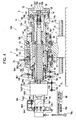
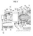
- a workpiece support device 70A according to a modification of the embodiment is described with reference to Fig. 4 which is the overview, Fig. 5 which is the detailed left view of Fig. 4 , and Fig. 6 which is the detailed right view of Fig. 4 .
- the workpiece support device 70A of this modification similarly to the support device 70, is arranged at a position opposite to the position of an indexing device 60.
- the support device 70A and the indexing device 60 form a rotary indexer 50.
- the support device 70A of this modification differs from the support device 70 in that a support shaft 2 is rotationally driven by a driving motor 63 of the indexing device 60 via a workpiece W, that a chucking device serving as a coupling member 3 is a so-called power chuck and hence claws 3b are advanced and retracted in the radial direction by a fluid pressure, and that the position of the support device 70A opposite to the position of the indexing device 60 is adjusted by a feeder 30.
- like numerals refer like members with similar functions to those of respective members of the support device 70.
- a frame 1 includes first to fifth frame members 101 to 105.
- the first frame member 101 is mounted on a bed B of a machine tool.
- the second frame member 102 is fitted to the inner peripheral surface of the first frame member 101 and fixed to a not-workpiece-side end surface of the first frame member 101 by a bolt.
- the third frame member 103 is fitted to the inner peripheral surface of the second frame member 102 and fixed to a not-workpiece-side end surface of the second frame member 102 by a bolt.
- the fourth frame member 104 is fitted to the outer peripheral surface of the third frame member 103 and fixed to a not-workpiece-side end surface of the third frame member 103 by a bolt.
- the fifth frame member 105 is fitted to the inner peripheral surface of the first frame member 101 and fixed to a workpiece-side end surface of the first frame member 101 by a bolt.
- a countershaft 4 is provided by being fitted to the inner peripheral surface of the frame 1.
- the countershaft 4 includes a first countershaft member 141 fitted to the third and fifth frame members 103 and 105, and a second countershaft member 142 fitted to the inner peripheral surface of the first countershaft member 141, fixed to a not-workpiece-side end surface of the first countershaft member 141 by a bolt, and fitted to the fourth frame member 104.
- the support shaft 2 is provided by being fitted to the inner peripheral surface of the countershaft 4.
- the support shaft 2 includes a first support shaft member 121 provided at the not-workpiece side, and a second support shaft member 122 fitted to the outer peripheral surface of the first support shaft member 121 and fixed to a workpiece-side end surface of the first support shaft member 121 by a bolt.
- the support shaft 2 has a through hole along the central axis thereof for a power chuck device.
- a rolling bearing 9 is provided between the frame 1 and the countershaft 4.
- the rolling bearing 9 includes two tapered roller bearings. Both bearings are separated from each other in the axial direction by a positioning step portion provided at the inner peripheral surface of the first frame member 101.
- the outer ring of the not-workpiece-side tapered roller bearing and the outer ring of the workpiece-side tapered roller bearing are restricted from moving in the axial direction respectively toward the workpiece side and the not-workpiece side by the positioning step portion.
- the inner bearing of the workpiece-side tapered roller bearing is restricted from moving in the axial direction toward the workpiece side by an orthogonal-to-axis step-portion surface of the first countershaft member 141.
- the inner ring of the not-workpiece-side tapered roller bearing is restricted from moving in the axial direction toward the not-workpiece side by a pre-load nut screwed onto an external thread provided at the first countershaft member 141.
- a roller of the not-workpiece-side tapered roller bearing restricts the inner ring from moving in the axial direction toward the workpiece side via the outer ring.
- a roller of the workpiece-side tapered roller bearing restricts the inner ring from moving in the axial direction toward the not-workpiece side via the outer ring.
- the countershaft 4 and the frame 1 are configured to be relatively rotatable but not relatively movable in the axial direction via the rolling bearing 9.
- An appropriate pre-load is applied in advance to the two tapered roller bearings by the pre-load nut.
- the play in the axial direction between the countershaft 4 and the frame 1 is eliminated while smooth relative rotation of the countershaft 4 and the frame 1 is provided.
- a locking nut to be screwed at a distance draws the pre-load nut in the axial direction via a countersunk screw. Using a frictional force generated between the screwed surfaces, the pre-load nut is prevented from being loosened.
- a ball screw nut (not shown) is mounted to a bottom portion of the first frame member 101, the ball screw nut being a component of the feeder 30. Balls are embedded in the ball screw nut along a screw groove.
- Another component of the feeder 30 is a ball screw shaft 31 which extends in the axial direction of the support device 70A, in particular, in parallel to the axial direction of the inner peripheral surface of the frame 1.
- the ball screw shaft 31 is supported by a supporter (not shown) vertically arranged on the bed B of the machine tool, rotatably but not movably in the axial direction.
- the frame 1 moves on the bed B in the axial direction along a guide groove having a dovetail shape (not shown) provided at the bed B, by rotating the ball screw shaft 31 with a motor or a handle operated by the operator.
- the position of the support device 70A opposite to the position of the indexing device 60 is adjusted.
- An axial clamping device 6 includes a body member 6a having a flange part fixed to a workpiece-side end surface of the first countershaft member 141 by a bolt; a thin ring portion 6a1 formed at a cylindrical part of the body member 6a; a ring-shaped clamping pressure chamber 6b formed between the outer peripheral surface of the thin ring portion 6a1 and the inner peripheral surface of the first countershaft member 141; and a channel 6c provided in the first and second countershaft members 141 and 142, both ends of the channel 6c being open to the clamping pressure chamber 6b and the outer peripheral surface of the second countershaft member 142.
- a rotary joint is defined to include the outer peripheral surface of the second countershaft member 142 and the fourth frame member 104.
- the channel 6c communicates with a high-pressure fluid supply (not shown) via the rotary joint, a connector terminal 6f provided at the outer peripheral surface of the second frame member 102, and a pipe.
- the thin ring portion 6a1 functions as a pressing member provided at the countershaft 4.
- the diameter of the thin ring portion 6a1 decreases by the fluid pressure of the high-pressure fluid of the clamping pressure chamber 6b.
- the thin rig portion 6a1 presses the outer peripheral surface of the support shaft 2, and restricts relative movement of the countershaft 4 and the support shaft 2. The thin ring portion 6a1 thusly restricts relative movement of the countershaft 4 and the support shaft 2 in the axial direction.
- a detent device 11 is provided.
- the device 11 restricts relative rotation of the countershaft 4 and the support shaft 2 and permits relative movement in the axial direction of the countershaft 4 and the support shaft 2.
- the detent device 11 includes a retaining groove 11a extending in the outer peripheral surface of the support shaft 2 in the axial direction, and a pin serving as a retaining member 11c.
- the retaining member 11c is fitted into a through hole 11b penetrating through the countershaft 4 from the outer peripheral surface in the radial direction and reaching the retaining groove 11a.
- the retaining member 11c is also fitted into the retaining groove 11a.
- the fitting surfaces of the retaining member 11c and the retaining groove 11a are defined by two flat surfaces parallel to each other.
- the retaining groove 11a extends by a length which is greater than a permissible relative movement distance of the countershaft 4 and the support shaft 2.
- a rotational clamping device 7 includes a thin ring portion 7a1 formed at the third frame member 103, a ring-shaped clamping pressure chamber 7b formed between the outer peripheral surface of the thin ring portion 7a1 and the inner peripheral surface of the second frame member 102, and a channel 7c penetrating through the second frame member 102 from the outer peripheral surface of the second frame member 102 in the radial direction and communicating with the clamping pressure chamber 7b.
- the channel 7c communicates with a high-pressure fluid supply (not shown) via a connector terminal 7d provided at the outer peripheral surface of the second frame member 102, and a pipe.
- the thin ring portion 7a1 functions as a pressing member provided at the frame 1.
- the diameter of the thin ring portion 7a1 decreases by the fluid pressure of the high-pressure fluid of the clamping pressure chamber 7b.
- the thin ring portion 7a1 presses the outer peripheral surface of the countershaft 4, and restricts relative movement of the frame 1 and the countershaft 4.
- the thin ring portion 7a1 thusly restricts rotation of the countershaft 4. Accordingly, rotation of the support shaft 2, whose rotation relative to the countershaft 4 is restricted by the detent device 11, is clamped.
- the force generating device 5 includes a double-acting fluid-pressure cylinder device formed of the second countershaft member 142 of the countershaft 4 serving as a cylinder and the first support shaft member 121 of the support shaft 2 serving as a piston.
- An advance pressure chamber 5b1 is formed at the not-workpiece side and a retract pressure chamber 5c1 is formed at the workpiece side while a piston wall is arranged therebetween.
- a rotary joint is defined to include the inner peripheral surface of the fourth frame member 104 and the outer peripheral surface of the second countershaft member 142.
- the advance pressure chamber 5b1 and the retract pressure chamber 5c1 respectively communicate with connector terminals 5d and 5e provided at the outer peripheral surface of the fourth frame member 104 via the rotary joint, and via an advance channel 5b and a retract channel 5c made in the fourth frame member 104 and the second countershaft member 142.
- the advance pressure chamber 5b1 and the retract pressure chamber 5c1 are connected to the high-pressure fluid supply via a pipe, an electromagnetic on-off valve (not shown), and a regulator.
- the chucking device serving as the coupling member 3 includes a base 3c fitted to the outer peripheral surface of the second support shaft member 122 and fixed to a workpiece-side end surface of the second support shaft member 122 by a bolt, a claw guide member 3d fixed to a workpiece-side end surface of the base 3c by a bolt and having a plurality of radial guide grooves extending toward the central axis, a plurality of claw holding members 3f having protruding parts fitted to the radial guide grooves, a plurality of claws 3b respectively fixed to the inside of the claw holding members 3f in the radial direction, a contact surface member 3e fixed to a workpiece-side end surface of the claw guide member 3d and defining a contact surface 3a3 at a workpiece-side end surface of the contact surface member 3e, a claw advance/retract device 14 that moves the plurality of claws 3b in the radial direction via the claw holding members 3f, and a mount check device 15 that checks whether the
- the claw advance/retract device 14 includes a drawbar 14a fitted into the through hole at the central axis of the support shaft 2; a piece holder 14b screwed onto an external thread provided at the outer peripheral surface of a workpiece-side end portion of the drawbar 14a and fitted to the inner peripheral surface of the base 3c; a plurality of tilting pieces 14c fixed to the piece holder 14b; a plurality of engagement pieces 14g respectively housed in a plurality of radial grooves formed at the base 3c equally arranged on a circumference of the base 3c and extending in the axial direction, the engagement pieces 14g being respectively supported by pins 14f provided at the base 3c; a rotary fluid-pressure cylinder device 14d in which a casing 14d1 is fixed to a not-workpiece-side end portion of the first support shaft member 121 by a bolt via a cylinder holder 14e, and in which a piston rod 14d2 is screwed onto an external thread provided at the outer peripheral surface of a
- the mount check device 15 includes a piece holder 15b fixed to a workpiece-side end surface of the base 3c by a bolt, a slide piece 15a fitted into an insertion hole of the piece holder 15b, a spring 15c for urging the slide piece 15a to cause the slide piece 15a to protrude from the contact surface 3a3 of the contact surface member 3e, and the rotary joint device 14h.
- a channel 15d for high-pressure air is formed at the piston rod 14d2, the support shaft 2, the piece holder 15b, and the slide piece 15a.
- the channel 15d is open to a fitting surface of the piston rod 14d2 with respect to the rotary joint device 14h and open to a workpiece-side end surface of the slide piece 15a.
- an air exhaust nozzle is formed in the workpiece-side end surface of the slide piece 15a.
- the high-pressure air from the air supply 15g is supplied to a connector terminal 15f provided at the casing 14h1 of the rotary joint device 14h via an electromagnetic on/off valve and a pipe to which a pressure sensor 15e is branch-connected.
- the high-pressure air is exhausted from the air exhaust nozzle of the slide piece 15a via the rotary joint device 14h and the channel 15d.
- an axial position sensor 13 of the support shaft 2 is provided at the not-workpiece side of the support device 70A.
- the axial position sensor 13 detects advance by a distance exceeding a permissible limit and a retract limit of the support shaft 2 which is advanced and retracted by the force generating device 5.
- the axial position sensor 13 of this modification includes a pair of sensors 13a and a ring-shaped detection object 13b.
- the pair of sensors 13a is fixed to an axially long hole of a sensor holder 13c fixed to the frame 1 such that the positions in the axial direction of the sensors 13a are adjustable.
- the detection object 13b is fixed to the outer peripheral surface of the cylinder holder 14e and thusly fixed to the support shaft 2 via the cylinder holder 14e.
- the workpiece-side sensor 13a is used for error detection, such as a coupling error of the workpiece W and an installation error of the support device 70A.
- This sensor 13a detects the detection object 13b when the support shaft 2 is advanced by a predetermined distance or greater, and outputs an error detection signal to a control device of the machine tool via a control device 80.
- the control device of the machine tool outputs an operation inhibition signal in response to the error detection signal.
- the not-workpiece side sensor 13a detects the retract limit of the support shaft 2.
- the sensor 13a When this sensor 13a detects the detection object 13b, the sensor 13a outputs a retract completion signal to the control device of the machine tool via the control device 80.
- the control device of the machine tool stops the supply of the high-pressure fluid from the high-pressure fluid supply in response to the retract completion signal. It is to be noted that the figure is provided for convenience of description, and therefore, the pair of sensors 13a is not illustrated at correct positions in the axial direction.
- the machining procedure of machining the workpiece W using the rotary indexer 50 is described below.
- the operator operates a handle to rotate the ball screw shaft 31, to move the support device 70A along the guide groove at the bed B, and to adjust the position of the support device 70A opposite to the position of the indexing device 60 depending on the length of the workpiece W.
- the operator fixes and couples the first end of the workpiece W to a workpiece mounting jig 65 of a rotary shaft 62 of the indexing device 60, and then operates an activation switch of the force generating device 5, the switch provided on an operation panel of the machine tool.
- the control device 80 opens a supply valve and closes an exhaust valve at an advance electromagnetic on/off valve, and closes a supply valve and opens an exhaust valve at a retract electromagnetic on/off valve, in response to an activation signal of the force generating device 5 from the control device of the machine tool. Accordingly, the high-pressure fluid is supplied from the high-pressure fluid supply to the advance pressure chamber 5b1 with a predetermined pressure, and exhausted from the retract pressure chamber 5c1.
- the control device 80 opens the electromagnetic on/off valve of the mount check device 15 to exhaust air from the air exhaust nozzle at the slide piece 15a.
- the support shaft 2 is advanced, and the contact surface 3a3 of the chucking device contacts the second end surface of the workpiece W, thereby pressing the end surface by a force corresponding to the predetermined pressure of the high-pressure fluid. Accordingly, the air exhausted from the air exhaust nozzle is interrupted, and the air pressure in the pipe increases.
- the air pressure is measured by a pressure sensor 15e.
- the control device 80 causes a mounting completion lamp (not shown) of the machine tool to blink if the input measured value of the pressure sensor 15e exceeds a threshold value.
- the play in the axial direction between the rotary shaft 62 of the indexing device 60 and the support shaft 2 of the support device 70A is eliminated by the workpiece W, in particular, by a reaction force applied by the workpiece W. Also, the play in the axial direction between the ball screw nut provided at the frame 1 and the ball screw shaft 31 is eliminated by a reaction force added from the workpiece W via the frame 1.
- the operator operates an activation switch of the claw advance/retract device 14, the switch provided on the operation panel of the machine tool.
- the control device 80 opens a holding electromagnetic on/off valve and closes a releasing electromagnetic on/off valve, in response to the activation signal of the claw advance/retract device 14 from the control device of the machine tool.
- the high-pressure air is supplied to the rotary joint device 14h from the air supply 15g via the regulator, the electromagnetic on/off valve, the pipe, and the holding connector terminal 14i.
- the high-pressure air enters a channel (not shown) made in the piston rod 14d2 via the rotary joint device 14h, and is supplied to a drawbar retract pressure chamber (not shown) of the rotary fluid-pressure cylinder device 14d.
- the drawbar 14a coupled to the piston rod 14d2 moves through the through hole of the support shaft 2 toward the not-workpiece side.
- the plurality of tilting pieces 14c fixed to the piece holder 14b move toward the not-workpiece side.
- the engagement pieces 14g rotate by the movement of the tilting pieces 14c toward the not-workpiece side, to move the claw holding members 3f having engagement recesses to the inside in the radial direction.
- the plurality of claw holding members 3f are respectively guided by the plurality of radial guide grooves of the claw guide member 3d.
- the plurality of claws 3b holds the outer peripheral surface of the workpiece W with a pressing pressure corresponding to a predetermined air pressure. Accordingly, the second end of the workpiece W is fixed and coupled to the support shaft 2.
- a drawbar displacement sensor 14k is provided at the claw advance/retract device 14.
- the drawbar displacement sensor 14k detects retract by a distance exceeding a retract limit and advance completion of the drawbar 14a.
- the drawbar displacement sensor 14k includes a pair of proximity sensors 14k2 and 14k3 mounted to the casing 14h1 of the rotary joint device 14h via a sensor holder 14k1 such that the positions in the axial direction of the proximity sensors 14k2 and 14k3 are adjustable, and a hollow cylinder 14k4 fixed to the casing 14h1 of the rotary joint device 14h.
- the hollow cylinder 14k4 is coaxially fixed to the piston rod 14d2.
- a ring-shaped detection object protruding to the outside in the radial direction is formed at the outer peripheral surface of a not-workpiece-side end portion of the hollow cylinder 14k4.
- the workpiece-side proximity sensor 14k2 outputs a holding failure signal to the control device 80 when this proximity sensor 14k2 detects retract by a distance exceeding the retract limit of the drawbar 14a.
- the proximity sensor 14k2 detects that the plurality of claws 3b is located at a movement limit position at the inside in the radial direction and hence the workpiece W may be held with a pressing force other than the predetermined pressing force. Thus, the claws 3b have to be adjusted or replaced.
- the control device 80 outputs the operation inhibition signal to the control device of the machine tool.
- the not-workpiece side proximity sensor 14k3 detects advance completion of the drawbar 14a when the workpiece W is released after machining is completed (described below). This proximity sensor 14k3 outputs a claw-retraction completion signal to the control device 80.
- the control device 80 stops the supply of the high-pressure air to a drawbar advance pressure chamber (not shown) of the rotary fluid-pressure cylinder device 14d.
- the operator operates a machining start switch provided on the operation panel of the machine tool.
- the control device 80 activates the axial clamping device 6 in response to a machining start signal input via the control device of the machine tool.
- the control device 80 opens the supply valve of the electromagnetic on/off valve of the axial clamping device 6, so that the high-pressure fluid is supplied from the high-pressure fluid supply to the clamping pressure chamber 6b.
- control device of the machine tool outputs a predetermined index angle signal to the control device 80.
- the control device 80 stops the driving motor 63 at a predetermined rotation index angle in accordance with an index angle signal.
- the control device 80 activates a clamping device (not shown) of the indexing device 60 to clamp the rotary shaft 62 after the driving motor 63 is stopped. Also, the control device 80 opens the supply valve and closes the exhaust valve of the electromagnetic on/off valve of the rotational clamping device 7, so as to supply the high-pressure fluid from the high-pressure fluid supply to the clamping pressure chamber 7b. Accordingly, the rotational clamping device 7 is activated, and the relative rotation of the frame 1 and the countershaft 4 is restricted.
- the workpiece W is integrally fixed to the frame 1. That is, the workpiece W is supported by the support device 70A not relatively movably.
- the workpiece W is machined by a tool of the machine tool while the first and second ends of the workpiece W are held by the indexing device 60 and the support device 70A not relatively movably.
- the control device of the machine tool When machining of the workpiece W at the predetermined workpiece index angle is completed, the control device of the machine tool outputs a next predetermined index angle signal to the control device 80 for machining at a next predetermined workpiece index angle.
- the control device 80 deactivates the clamping device of the indexing device 60 and the rotational clamping device 7 in accordance with the index angle signal. Then, the control device 80 rotates the driving motor 63 and stops the driving motor 63 at a next predetermined index angle.
- the control device 80 activates the clamping device of the indexing device 60 and the rotational clamping device 7 after the driving motor 63 is stopped, so that the workpiece W is machined in a similar condition to that at the previous predetermined workpiece index angle.
- the control device 80 deactivates the clamping device of the indexing device 60 and the rotational clamping device 7, and also deactivates the axial clamping device 6.
- the operator operates a deactivation switch of the claw advance/retract device 14, the switch provided on the operation panel of the machine tool.
- the control device 80 closes the holding electromagnetic on/off valve and opens the releasing electromagnetic on/off valve, in response to the deactivation signal of the claw advance/retract device 14 from the control device of the machine tool.
- the high-pressure air is supplied from the releasing connector terminal 14j to the rotary joint device 14h.
- the high-pressure air enters a channel (not shown) made in the piston rod 14d2 via the rotary joint device 14h, and is supplied to the drawbar advance pressure chamber (not shown) of the rotary fluid-pressure cylinder device 14d.
- the drawbar 14a coupled to the piston rod 14d2 moves toward the workpiece side.
- the plurality of tilting pieces 14c fixed to the piece holder 14b move toward the workpiece side.
- the engagement pieces 14g rotate by the movement of the tilting pieces 14c toward the workpiece side, to move the claw holding members 3f to the outside in the radial direction.
- the plurality of claws 3b is retracted from the outer peripheral surface of the workpiece W to the outside in the radial direction, and hence the workpiece W is released.
- the operator operates a deactivation switch of the force generating device 5, the switch provided on the operation panel of the machine tool.
- the high-pressure fluid is supplied from the high-pressure fluid supply to the retract pressure chamber 5c1, and exhausted from the advance pressure chamber 5b1, thereby retracting the support shaft 2.
- the contact surface 3a3 of the contact surface member 3e is separated from the second end surface of the workpiece W, and hence the second end of the workpiece W becomes detachable.
- the not-workpiece-side sensor 13a detects the detection object 13b when the support shaft 2 is retracted. Then, this sensor 13a outputs a retract completion signal to the control device of the machine tool via the control device 80.
- the supply of the high-pressure fluid from the high-pressure fluid supply is stopped.
- the operator detaches the workpiece W from the workpiece mounting jig 65 of the indexing device 60, and thusly the machined workpiece W is detached from the rotary indexer 50.
- a support device 70B according to another modification is schematically illustrated in Fig. 7 .
- the workpiece support device 70B of this modification similarly to the support device 70 or 70A, is arranged at a position opposite to the position of an indexing device 60.
- the support device 70B and the indexing device 60 form a rotary indexer 50.
- the support.device 70B differs from the support device 70 or 70A in that, while the countershaft 4 and the frame 1 are configured to be relatively rotatable but not relatively movable in the axial direction via the rolling bearing 9 in the support device 70 or 70A, a support shaft 2 and a countershaft 4 are configured to be relatively rotatable but not relatively movable in the axial direction via a rolling bearing 9 in this modification.
- the position of the support device 70B opposite to the position of the indexing device 60 is adjusted depending on the length of a workpiece W by a feeder 30 in a similar manner to the support device 70A.
- a force generating device 5 employs a fluid-pressure cylinder device formed of the frame 1 serving as a cylinder and the countershaft 4 serving as a piston.
- High-pressure fluid supplied from a high-pressure fluid supply (not shown) is supplied to an advance pressure chamber 5b1 located at the not-workpiece side and to a retract pressure chamber 5c1 located at the workpiece side via an advance channel 5b and a retract channel 5c formed at the frame 1.
- the force generating device 5 employs the fluid-pressure cylinder device.
- the force generating device 5 may employ a structure other than the fluid-pressure cylinder device.
- the countershaft 4 is moved in the axial direction by a torque motor via a motion converting device, such as a ball screw device, so that the support shaft 2 is pressed or drawn by a force corresponding to a predetermined torque of the torque motor.
- a motion converting device such as a ball screw device
- An axial clamping device 6 is provided at the frame 1 as shown in a schematic illustration.
- high-pressure fluid is supplied from a high-pressure fluid supply (not shown) to a ring-shaped clamping pressure chamber 6b formed at the frame 1 via a channel 6c formed at the frame 1. Accordingly, the diameter of a thin ring portion 6a1 decreases and the thin ring portion 6a1 holds the outer peripheral surface of the countershaft 4, thereby restricting relative movement of the frame 1 and the countershaft 4.
- the axial clamping device 6 thusly restricts the relative movement in the axial direction of the frame 1 and the countershaft 4.
- a detent device 11 is provided between the frame 1 and the countershaft 4.
- a flanged pin serving as a retaining member 11c is inserted through a through hole 11b formed at the frame 1.
- the tip end of the flanged pin is fitted into a retaining groove 11a formed at the outer peripheral surface of the countershaft 4 and extending in the axial direction by a length of at least a relative movement limit of the frame 1 and the countershaft 4.
- the retaining member 11c can be removed from the detent device 11 in this modification.
- the detent device 11 can be even deactivated depending on a situation.
- Two bearings which serve as the rolling bearing 9, are disposed between the inner peripheral surface of the countershaft 4 and the outer peripheral surface of the support shaft 2 at a distance from each other in the axial direction.
- the outer ring of the not-workpiece-side bearing is restricted from moving in the axial direction toward the not-workpiece side by an orthogonal-to-axis step-portion surface of the countershaft 4.
- the outer ring of the workpiece-side bearing is restricted from moving in the axial direction toward the workpiece side by a stop ring 1g fixed to the inner peripheral surface of the countershaft 4.
- the inner rings of the two bearings are restricted from moving in the axial direction toward the workpiece side and the not-workpiece side by an orthogonal-to-axis step-portion surface of the support shaft 2, a stop ring 1g fixed to the outer peripheral surface of the support shaft 2, and a distance collar 1f.
- the outer and inner rings of the bearings are restricted from moving in the axial direction by a rolling member.
- the support shaft 2 and the countershaft 4 are configured to be relatively rotatable but not relatively movable in the axial direction via the rolling bearing 9. It is noted that this modification is schematically illustrated, and the rolling bearing 9 employs a radial bearing.
- a rotational clamping device 7 is provided at the countershaft 4 as shown in a schematic illustration.
- high-pressure fluid is supplied from a high-pressure fluid supply (not shown) to a ring-shaped clamping pressure chamber 7b formed at the countershaft 4 via a channel 7c formed at the countershaft 4. Accordingly, the diameter of a thin ring portion 7a1 decreases and the thin ring portion 7a1 holds the outer peripheral surface of the support shaft 2, thereby restricting relative movement of the countershaft 4 and the support shaft 2.
- the rotational clamping device 7 thusly restricts the relative rotation of the countershaft 4 and the support shaft 2.
- the support shaft 2 is clamped in a manner not rotatable relative to the frame 1 via the countershaft 4 which is restricted from moving in the axial direction and rotating relative to the frame 1 by the activation of the axial clamping device 6.
- a chucking device which serves as a coupling member 3, is fixed to a workpiece-side end portion of the support shaft 2.
- the coupling member 3 includes a base 3a, a plurality of claws 3b, and a contact surface 3a3.
- a drive 8 of the support shaft 2 is provided, which is schematically illustrated.
- the drive 8 includes a dedicated driving motor M mounted to the countershaft 4 via a bracket 8d, and a gear mechanism 8f.
- the gear mechanism 8f includes a gear 8f1 fixed to the support shaft 2 and a gear 8f2 fixed to a rotary shaft of the dedicated driving motor M.
- the machining procedure of machining the workpiece W using the rotary indexer 50 is described below.
- the operator operates a handle to rotate the ball screw shaft 31.
- the support device 70B is moved along a guide groove at a bed B.
- the position of the support device 70B opposite to the position of the indexing device 60 is adjusted depending on the length of the workpiece W.
- the operator fixes and couples the first end of the workpiece W to a workpiece mounting jig 65 of a rotary shaft 62 of the indexing device 60, and then operates an activation switch of the force generating device 5, the switch provided on an operation panel of a machine tool.
- a control device 80 supplies high-pressure fluid to an advance pressure chamber 5b1 in response to an activation signal of the force generating device 5 from a control device of the machine tool.
- the support shaft 2 is advanced with the countershaft 4.
- the contact surface 3a3 presses the second end surface of the workpiece W by a force corresponding to a predetermined pressure of the high-pressure fluid.
- the play in the axial direction between the rotary shaft 62 of the indexing device 60 and the support shaft 2 of the support device 70B is eliminated by the workpiece W.
- the play in the axial direction between the ball screw nut provided at the frame 1 and the ball screw shaft 31 is eliminated by a reaction force added from the workpiece W via the frame 1.
- the operator operates a claw advance/retract mechanism of the coupling member 3 so as to hold the outer peripheral surface of the workpiece W by a plurality of claws 3b.
- the control device 80 activates the axial clamping device 6 in response to a machining start signal input via the control device of the machine tool.
- the control device of the machine tool outputs a predetermined index angle signal to the control device 80.
- the control device 80 synchronously rotates the driving motor 63 and the dedicated driving motor M in accordance with an index angle signal, and stops the driving motor 63 and the dedicated driving motor M at a predetermined rotation index angle.
- the control device 80 activates a clamping device of the indexing device 60 and the rotational clamping device 7 after the motors 63 and M are stopped.
- the workpiece W is machined by a tool of the machine tool while the workpiece W is held by the indexing device 60 and the support device 70B not relatively movably.
- the control device 80 deactivates the clamping device of the indexing device 60 and the rotational clamping device 7, and also deactivates the axial clamping device 6.
- the operator operates the claw advance/retract mechanism of the coupling member 3 to retract the plurality of claws 3b, thereby releasing chucking of the workpiece W.
- the deactivation switch of the force generating device 5 on the operation panel of the machine tool is operated, the high-pressure fluid is supplied to the retract pressure chamber 5c1, the support shaft 2 is retracted with the countershaft 4, and the contact surface 3a3 is separated from the second end surface of the workpiece W.
- the operator detaches the workpiece W from the workpiece mounting jig 65 of the indexing device 60.
- the control device 80 synchronously rotates the driving motor 63 of the indexing device 60 and the dedicated driving motor M of the support device 70B. Accordingly, a correct workpiece index angle can be obtained.
- the workpiece W can be machined with high accuracy without being twisted and deformed during indexing and during machining at a predetermined workpiece index angle.
- the force generating device 5 is activated, and the play in the axial direction between the support shaft 2 and the rotary shaft 62 of the indexing device 60 is eliminated by the workpiece W. Accordingly, the workpiece W can be machined with further high accuracy without moving in the axial direction or vibrated due to the machining force from the tool.
- a workpiece support device 70C according to still another modification of the embodiment is described with reference to Fig. 8 which is the overview, Fig. 9 which is the detailed left view of Fig. 8 , and Fig. 10 which is the detailed right view of Fig. 8 .
- the workpiece support device 70C of this modification similarly to the support device 70, 70A, or 70B, is arranged at a position opposite to the position of an indexing device 60.
- the support device 70C and the indexing device 60 form a rotary indexer 50.
- a chucking device which serves as a coupling member 3, includes a claw advance/retract device 14 as a so-called power chuck device, and a mount check device 15 that checks whether a contact surface 3a3 contacts a workpiece W or not.
- the support device 70C differs from the support device 70A in that the support device 70C in this modification does not have a countershaft 4, and a support shaft 2 slides on the inner peripheral surface of a frame 1 directly or indirectly via a sliding bearing 22 using, for example, sintered substance containing metal.
- the support shaft 2 slides on the inner peripheral surface of the frame 1 via the sliding bearing 22.
- the frame 1 includes first to fifth frame members 201 to 205.
- the first frame member 201 is mounted on a bed B of a machine tool.
- the second frame member 202 is fitted to the inner peripheral surface of the first frame member 201 and fixed to a not-workpiece-side end surface of the first frame member 201 by a bolt.
- the third frame member 203 is fitted to the inner peripheral surface of the first frame member 201 and fixed to a workpiece-side end surface of the first frame member 201 by a bolt.
- the fourth frame member 204 is fitted to the inner peripheral surface of the second frame member 202.
- the fifth frame member 205 is fixed to a not-workpiece-side end surface of the second frame member 202 by a bolt, and serving as a positioning member for relative positions of the second and fourth frame members 202 and 204 in the axial direction.
- the fourth frame member 204 extends from a fitting surface thereof with respect to the second frame member 202 to a workpiece-side end of the third frame member 203 in the axial direction.
- a housing space 206 of the support shaft 2 is formed in a ring shape.
- the housing space 206 extends in the axial direction along the outside of the fourth frame member 204 in the radial direction and the workpiece side of the housing space 206 is open.
- the sintered substance containing metal, serving as the sliding bearing 22, is press fitted to the inner peripheral surfaces of the first frame member 201 and the third frame member 203.
- the support shaft 2 includes first to fifth support shaft members 221 to 225.
- the first support shaft member 221 is fitted to the inner peripheral surface of the sliding bearing 22 and inserted into the housing space 206.
- the second support shaft member 222 is inserted into an axial through hole of the fourth frame member 204, a workpiece-side-end outer peripheral surface of the second support shaft member 222 being fitted to the first frame member 201, a workpiece-side-end orthogonal-to-axis step-portion surface of the second support shaft member 222 being fixed to the first frame member 201 by a bolt.
- the third and fourth support shaft members 223 and 224 being in contact with each other and fitted to the inner peripheral surface of the first frame member 201, the third support shaft member 223 being disposed at the not-workpiece side, the fourth support shaft member 224 being disposed at the workpiece side.
- the fifth support shaft member 225 has a cylindrical part fitted to the inner peripheral surface of the third support shaft member 223, and a flange part fixed to a not-workpiece-side end surface of the first support shaft member 221 by a bolt, to hold the third and fourth support shaft members 223 and 224 between the fifth support shaft member 225 and the first support shaft member 221.
- An axial clamping device 6 in this modification includes a body member 6a having a flange part fixed to an orthogonal-to-axis step-portion surface of the first frame member 201 by a bolt, a thin ring portion 6a1 formed at a cylindrical part of the body member 6a, a ring-shaped clamping pressure chamber 6b formed between the outer peripheral surface of the thin ring portion 6a1 and the inner peripheral surface of the first frame member 201, and a channel 6c provided at the first frame member 201, the channel 6c being open to a not-workpiece-side end surface of the first frame member 201 and to the clamping pressure chamber 6b.
- the channel 6c communicates with a high-pressure fluid supply (not shown) via a connector terminal 6f provided at a not-workpiece-side end surface of the first frame member 201, and a pipe.
- the thin ring portion 6a1 functions as a pressing member provided at the frame 1.
- the diameter of the thin ring portion 6a1 decreases by the fluid pressure of the high-pressure fluid of the clamping pressure chamber 6b.
- the thin ring portion 6a1 presses the outer peripheral surface of the support shaft 2, and restricts relative movement in the axial direction and relative rotation of the frame 1 and the support shaft 2.
- a force generating device 5 in this modification includes a double-acting fluid-pressure cylinder device formed of the third support shaft member 223 serving as a cylinder and the fourth frame member 204 serving as a piston. Since the piston of the fluid-pressure cylinder device is the frame 1 which is a fixed member, the cylinder slides relative to the fixed piston.
- the fifth support shaft member 225 fixed to the not-workpiece side of the third support shaft member 223 and the fourth support shaft member 224 fixed to the not-workpiece side of the third support shaft member 223 are slidably fitted to the outer peripheral surface of the fourth frame member 204.
- an advance pressure chamber 5b1 is formed at the workpiece side and a retract pressure chamber 5c1 is formed at the not-workpiece side while a piston wall formed at the fourth frame member 204 is arranged therebetween.
- the advance pressure chamber 5b1 and the retract pressure chamber 5c1 respectively communicate with connector terminals 5d and 5e provided at the outer peripheral surface of the second frame member 202 via an advance channel 5b and a retract channel 5c made in the fourth frame member 204 and the second frame member 202.
- the advance pressure chamber 5b1 and the retract pressure chamber 5c1 are connected to a high-pressure fluid supply via a pipe, an electromagnetic on-off valve (not shown), and a regulator.
- Two circular grooves are formed at fitting surfaces of the second frame member 202 and the fourth frame member 204, the grooves respectively corresponding to the advance channel 5b and the retract channel 5c. Regardless of the press-fit phase, the advance channel 5b and the retract channel 5c at the second frame member 202 are connected to those at the fourth frame member 204.
- the chucking device serving as the coupling member 3 in this modification is provided at a workpiece-side end portion of the support shaft 2 in a similar manner to the support device 70A.
- the chucking device includes a claw advance/retract device 14 and a mount check device 15 in a similar manner to the support device 70A.
- the claw advance/retract device 14 in this modification includes a drawbar displacement sensor 14k in a similar manner to the support device 70A.
- an axial position sensor 13 of the support shaft 2 is provided at the not-workpiece side of the support device 70C in a similar manner to the support device 70 or 70A.
- the machining procedure of machining the workpiece W using the rotary indexer 50 is described below.
- the operator fixes and couples the first end of the workpiece W to a workpiece mounting jig 65 of a rotary shaft 62 of the indexing device 60, and then operates an activation switch of the force generating device 5, the switch provided on an operation panel of the machine tool.
- the play in the axial direction between the rotary shaft 62 of the indexing device 60 and the support shaft 2 of the support device 70C is eliminated by the workpiece W.
- the play in the axial direction between a ball screw nut provided at the frame 1 and a ball screw shaft 31 is eliminated by a reaction force added from the workpiece W via the frame 1.
- the operator operates an activation switch of the claw advance/retract device 14, the switch provided on the operation panel of the machine tool.
- the second end of the workpiece W is held by the chucking device and coupled to the support shaft 2.
- the operator operates a machining start switch provided on the operation panel of the machine tool.
- the control device of the machine tool outputs a predetermined index angle signal to the control device 80 in response to a machining start signal from the machining start switch.
- the control device 80 stops the driving motor 63 at a predetermined rotation index angle in accordance with an index angle signal.
- the control device 80 activates a clamping device (not shown) of the indexing device 60 after the driving motor 63 is stopped, so as to clamp the rotary shaft 62. Also, the control device 80 activates the axial clamping device 6.
- the workpiece W is integrally fixed to the frame 1 via the coupling member 3 and the support shaft 2.
- the workpiece W is machined by a tool of the machine tool while the first and second ends of the workpiece W are supported by the indexing device 60 and the support device 70C not relatively movably.
- the control device of the machine tool outputs a next predetermined index angle signal to the control device 80 for machining at a next predetermined workpiece index angle.
- the control device 80 deactivates the clamping device of the indexing device 60 and the axial clamping device 6 in accordance with the index angle signal. Then, the control device 80 rotates the driving motor 63 and stops the driving motor 63 at a next predetermined index angle.
- the control device 80 activates the clamping device of the indexing device 60 and the axial clamping device 6 after the driving motor 63 is stopped, so that the workpiece W is machined in a similar condition to that at the previous predetermined workpiece index angle.
- the control device 80 deactivates the clamping device of the indexing device 60 and the axial clamping device 6.
- the operator operates a deactivation switch of the claw advance/retract device 14, the switch provided on the operation panel of the machine tool, so as to release the workpiece W.
- the operator operates a deactivation switch of the force generating device 5, the switch provided on the operation panel of the machine tool, so as to retract the support shaft 2.
- the supply of the high-pressure fluid from the high-pressure supply is stopped.
- the operator detaches the workpiece W from the workpiece mounting jig 65 of the indexing device 60, and thusly the machined workpiece W is detached from the rotary indexer 50.
- the force generating device 5 is activated from when the operator operates the activation switch of the force generating device 5 to when the operator operates the deactivation switch on the operation panel of the machine tool, and hence, the force generating device 5 is continuously activated during machining of the workpiece W.
- the force generating device 5 may be deactivated automatically or manually by operating the deactivation switch by the operator during machining at a predetermined workpiece index angle after the axial clamping device 6 is activated.
- the force generating device 5 is preferably continuously activated during machining of the workpiece W in a similar manner to this modification.
- the rotary indexer 50 can carry out, in addition to such indexing machining in which the rotation of the workpiece W is stopped and held at a predetermined index angle, indexing machining during rotating the workpiece W, and turning machining of the workpiece W, with or without indexing machining.
- the force generating device 5 is activated, but the axial clamping device 6 is not activated and is brought into the deactivated state.
- machining may be carried out while the workpiece W is pressed by the force generating device 5, or while the workpiece W is drawn by the force generating device 5.
Landscapes
- Engineering & Computer Science (AREA)
- Mechanical Engineering (AREA)
- Machine Tool Positioning Apparatuses (AREA)
- Machine Tool Units (AREA)
- Jigs For Machine Tools (AREA)
Abstract
A workpiece support device (70) includes a coupling member (3) that couples a second end of a workpiece (W); a support shaft (2), the coupling member (3) provided at a first end of the support shaft (2); a frame (1) that supports the support shaft (2) axially movably and rotatably; a force generating device (5) that applies a force in an axial direction to the support shaft (2); and an axial clamping device (6) including a single pressing member (6a1) extending along the entire periphery of the support shaft (2) or a plurality of pressing members (6a1) equally arranged in a circumferential direction of the support shaft (2), the pressing member (6a1) generating a force in a radial direction while the force generating device (5) is activated, the axial clamping device (6) fixing the support shaft (2) to the frame (1) in the axial direction by the force.
Description
- The present invention relates to a workpiece support device, the support device supporting a second end of the workpiece while a first end of the workpiece is coupled to a rotary shaft of a rotary drive. The present invention also relates to a rotary indexer including the workpiece support device, an indexing device serving as the rotary drive provided at a position opposite to the position of the support device, and a control device.
- The above-described rotary drive arranged at the position opposite to the position of the workpiece support device may be an indexing device mounted on a machine tool, or a spindle head of a machine tool such as a lathe. The indexing device provided at the position opposite to the position of the workpiece support device may be an indexing device mounted on a machine tool, or a spindle head of a machine tool such as a combined lathe having an indexing function.
- The workpiece support device may be a tailstock arranged at a position opposite to the position of a lathe headstock that holds a first end surface of a workpiece. In a tailstock disclosed in Japanese Unexamined Patent Application Publication No.
10-6105 - As described above, although the play in the axial direction of the rotary shaft of the headstock, the tailstock shaft, and the tailstock sleeve is eliminated by the pressed workpiece, the play in a radial direction provided between the frame and the tailstock sleeve is not eliminated. Thus, the tailstock center supported by the tailstock sleeve via the tailstock shaft is movable in a radial direction relative to the frame. In addition, the tailstock center and a second end of the workpiece are restricted from relatively moving in the axial direction, but not sufficiently restricted from moving in the radial direction, by a pressing force applied by the tailstock center to the center bore. Since the second end of the workpiece is not sufficiently restricted from moving in the radial direction by the tailstock, when a part of the workpiece near the second end of the workpiece is to be machined, the workpiece may be moved in the radial direction and vibrated, bent, or twisted, by the machining force applied by the tool in a direction intersecting with a plane containing the axis of the tailstock shaft, for example, a direction orthogonal to the plane. The workpiece is machined while being vibrated or deformed. This may deteriorate machining accuracy. When turning is carried out, rotation deflection occurs. This may deteriorate surface roughness in addition to the machining accuracy.
- The present invention is made in light of the above situations. An object of the present invention is to improve machining accuracy of a workpiece while a first end of the workpiece is coupled to a rotary shaft of a rotary drive.
- According to an aspect of the present invention, a workpiece support device is configured to support a second end of a workpiece while a first end of the workpiece is coupled to a rotary shaft of a rotary drive. The support device includes a coupling member configured to couple the second end of the workpiece; a support shaft, the coupling member provided at a first end of the support shaft; a frame configured to support the support shaft movably in an axial direction and rotatably; a force generating device configured to apply a force in the axial direction to the support shaft; and an axial clamping device including a single pressing member extending along the entire periphery of the support shaft or a plurality of pressing members equally arranged in a circumferential direction of the support shaft, the pressing member generating a force in a radial direction while the force generating device is activated, the axial clamping device fixing the support shaft to the frame in the axial direction by the force.
- With the above configuration, the second end of the workpiece is coupled to the support shaft via the coupling member while the first end of the workpiece is coupled to the rotary shaft of the rotary drive, and the axial clamping device is activated to fix the support shaft in the axial direction while the force generating device presses or draws the second end of the workpiece via the support shaft and the coupling member. Accordingly, a play in the axial direction between the support shaft and the rotary shaft is eliminated by the workpiece, that is, a reaction force from the workpiece. Also, while the force generating device is activated, the axial clamping device is activated and the force in the radial direction is equally applied to the periphery of the support shaft. Accordingly, a play in the radial direction of the support shaft is eliminated, and the support shaft is continuously coaxial with the rotary shaft. Thus, the rotary shaft, the workpiece, and the support shaft are integrated while the rotary shaft is continuously coaxial with the support shaft. Also, the workpiece is supported by the rotary shaft and the support shaft with the play eliminated in the axial direction and the radial direction. The workpiece is machined without being moved or vibrated by a load in the axial direction applied from a tool, i.e., a machining force in the axial direction. Also, the workpiece is machined while a coaxial state is maintained without being vibrated or deformed in the radial direction by a load in the radial direction applied from the tool, i.e., a machining force in the radial direction. Therefore, the workpiece can be machined with high accuracy.
- The support shaft may be directly supported by the frame. However, to improve machining accuracy of the workpiece during rotational machining, the following configuration is preferable. In particular, the workpiece support device further includes a countershaft provided at the outside in the radial direction of the support shaft coaxially with the support shaft. The frame supports the support shaft movably in the axial direction and rotatably in association with the countershaft. One of pairs including a pair of the support shaft and the countershaft and a pair of the countershaft and the frame is configured to be relatively rotatable but not relatively movable in the axial direction via a rolling bearing. The pressing member of the axial clamping device is supported by an outer member in the radial direction of the other one of the pairs, the axial clamping device applying a pressing force as a force in the radial direction to the outer peripheral surface of an inner member in the radial direction of the other one of the pairs.
- With the above configuration, the frame and the countershaft support the support shaft movably in the axial direction and rotatably in association with each other. Accordingly, the support shaft is rotatable even when the axial clamping device is activated and movement in the axial drection of the support shaft is resticted. The workpiece is rotatable while movement in the axial direction and movement in the radial direction at the second end of the workpiece are restricted. Accordingly, rotational machining of the workpiece (turning machining, indexing machining in correspondence with a phase angle of the workpiece during continous rotation) can be carried out with high accuracy.
- In the above configuration, the support shaft does not have to be actively held not rotatably. However, to improve the machining accuracy of the workpiece when the rotation of the rotary drive is stopped, the following configuration is provided. In particular, the support device further includes a rotational clamping device configured to restrict relative rotation of the one of the pairs.
- With the above configuration, by activating the rotational clamping device in addition to the axial clamping device, the movement in the axial direction and the rotation of the supoprt shaft are restricted. When machining is carried out while the rotation of the rotary drive is stopped, the workpiece is prevented from being rotated at the second end of the workpiece, i.e., from being twisted by a machining force in a direction intersecting with a plane containing the axis, for example, in a direction orthogonal to the plane containing the axis, which is a machining force applied at a position deviated from the axis in the direction intersecting with the plane. Accordingly, the workpiece is machined without being deformed, thereby improving the machining accuracy.
- In the above configuration, the first end of the workpiece may be coupled to the rotary shaft of the rotary drive without an indexing function. However, the first end of the workpiece W may be coupled to a rotary shaft of an indexing device so that the workpiece support device forms a rotary indexer. In particular, a rotary indexer according to a second aspect of the present invention is provided which includes the workpiece support device of the first aspect; an indexing device serving as the rotary drive provided at a position opposite to the position of the support device and including the rotary shaft to which the first end of the workpiece is coupled; and a control device. The control device deactivates the rotational clamping device when the indexing device is rotated, and activates the rotational clamping device when the rotation of the indexing device is stopped.
- With the above configuration, while the force generating device is activated, when the axial clamping device is activated, the play in the axial direction between the support shaft and the rotary shaft is eliminated. Also, the support shaft is restricted from moving in the axial direction relative to the frame while the play in the radial direction between the support shaft and the frame is eliminated while a coaxial state is maintained. In this state, the control device deactivates the rotational clamping device when the indexing device is rotated. Accordingly, correct rotational indexing and highly accurate turning machining of the workpiece can be carried out. Also, the control device activates the rotational clamping device when the rotation of the indexing device is stopped. Accordingly, the support shaft is restricted from moving in the axial direction and from rotating. The workpiece is machined without being moved and vibrated in the axial direction by a machining force and wihtout being rotated and twisted at the second end of the workpiece by the machining force. Hence, the workpiece is machined without being deformed, thereby improving the machining accuracy.
- Alternatively, when an indexing device is provided as the rotary drive, in the support device, the pressing member of the axial clamping device is supported by the frame and applies a pressing force as the force in the radial direction to the outer peripheral surface of the support shaft, and the support device fixes the support shaft to the frame not movably in the axial direction and not rotatably relative to the frame by the pressing force, the following configuration is provided. In particular, a rotary indexer according to a third aspect of the invention is provided which includes the workpiece support device of the first aspect; an indexing device serving as the rotary drive provided at a position opposite to the position of the support device and including the rotary shaft to which the first end of the workpiece is coupled; and a control device. The pressing member of the axial clamping device is supported by the frame and applies a pressing force as the force in the radial direction to the outer peripheral surface of the support shaft, and the support device fixes the support shaft to the frame not movably in the axial direction and not rotatably relative to the frame by the pressing force. The control device deactivates the axial clamping device and activates the force generating device when the indexing device is rotated, and activates the axial clamping device while the force generating device is activated when the rotation of the indexing device is stopped.
- The invention with the above configuration, since the control device deactivates the axial clamping device and activates the force generating device when the indexing device is rotated, the support shaft and the rotary shaft are rotated while the play in the axial direction is continuously eliminated. Accordingly, correct rotational indexing and highly accurate turning machining of the workpiece can be carried out. Also, since the control device activates the axial clamping device while the force generating device is activated when the rotation of the indexing device is stopped, movement in the axial direction, vibration, and rotation of the support shaft are restricted while the support shaft is coaxial with the frame. Thus, when the rotation of the indexing device is stopped, movemnet in the axial direction and vibration and rotation at the second end, i.e., twisting of the workpiece by a machining force are restricted. The workpiece is machined without being moved, vibrated, and deformed, thereby improving machining accuracy.
- In the rotary indexer, only the indexing device that supports the first end of the workpiece may carry out indexing for the workpiece, and the support shaft of the support device may be rotated via the workpiece. However, to improve indexing accuracy of the workpiece, and to improve the machining accuracy of rotational machining of the workpiece (turning machining, indexing machining in correspondence with a phase angle of the workpiece during rotating the workpiece), the following configuration is preferable. In particular, the rotary indexer further includes a drive configured to cause the support shaft to be rotated in the same manner as the indexing device.
- With the above configuration, since the drive is provided to cause the support shaft to be rotated in the same manner as the indexing device, both ends of the workpiece can be rotationally driven by the indexing device and the support device. The workpiece is rotated without being twisted. Accordingly, machining accuracy and indexing accuracy for indexing machining are improved. Also, machining accuracy for rotational machining is improved.
- The drive may cause the support shaft to be rotated in the same manner as the indexing device via a transmission mechanism, while a driving motor of the indexing device serves as a common drive source. To simplify the device, the following configuration is preferable. In particualr, the drive includes a dedicated driving motor which is different from a driving motor of the indexing device. The drive includes a control device configured to drive the dedicated driving motor synchronously with the driving motor of the indexing device.
- With the above configuration, the drive includes the dedicated driving motor which is different from the driving motor of the indexing device. The control device of the drive drives the dedicated driving motor synchronously with the driving motor of the indexing device. The drive does not include a transmission mechanism coupled to the driving motor of the indexing device. Accordingly, the drive can be simplified. Also, synchronization deviation between the support shaft and the rotary shaft due to the use of the above transmission mechanism does not occur. In particular, synchronization deviation between the support shaft and the rotary shaft does not occur, the deviation may be caused by a play or twisting of a transmission mechanism component such as a gear, a timing pulley, a timing belt, a coupling, and a shaft.
-
-
Fig. 1 illustrates overview of a workpiece support device according to an embodiment; -
Fig. 2 illustrates a left half portion of the workpiece support device inFig. 1 ; -
Fig. 3 illustrates a right half portion of the workpiece support device inFig. 1 ; -
Fig. 4 illustrates overview of a workpiece support device according to a modification of the embodiment; -
Fig. 5 illustrates a left half portion of the workpiece support device inFig. 4 ; -
Fig. 6 illustrates a right half portion of the workpiece support device inFig. 4 ; -
Fig. 7 schematically illustrates overview of a workpiece support device according to another modification of the embodiment; -
Fig. 8 illustrates overview of a workpiece support device according to still another modification of the embodiment; -
Fig. 9 illustrates a left half portion of the workpiece support device inFig. 8 ; -
Fig. 10 illustrates a right half portion of the workpiece support device inFig. 9 ; and -
Fig. 11 illustrates an indexing device of a rotary indexer. - A
rotary indexer 50 includes an indexing device 60 (Fig. 11 ) serving as a rotary drive, a workpiece support device 70 (Figs. 1 ,4 ,7 , and8 ) arranged at a position opposite to the position of theindexing device 60, and acontrol device 80 for bothdevices control device 80 controls thesupport device 70 in accordance with the operation of theindexing device 60. In therotary indexer 50, for example, when a long workpiece W is to be machined, theindexing device 60 holds a first end of the workpiece W and theworkpiece support device 70 holds a second end of the workpiece W. - In this embodiment, the
indexing device 60 is mounted on a bed B of a machine tool. In particular, the machine tool includes a rotary shaft of a tool such as a grindstone, an end mill, a drill, a tap, etc., or a holder of a tool such as a cutting tool, and the tool is driven by, for example, numerical control. Alternatively, theindexing device 60 may serve as a workpiece supporting part, such as a headstock of a combined lathe having an indexing function, and define a machine tool with a tool driving part. - The
indexing device 60 includes abody 61 mounted on and fixed to the bed B; arotary shaft 62 rotatably supported in thebody 61; a drivingmotor 63; a rotation transmission mechanism (not shown) provided in thebody 61, having a worm speed reduction device or the like, and transmitting a torque of the drivingmotor 63 to therotary shaft 62; a rotary table 64 provided at a first end of therotary shaft 62, the rotary table 64 rotating for indexing; and aworkpiece mounting jig 65 detachably attached to a workpiece mounting surface of the rotary table 64 by a bolt or the like, theworkpiece mounting jig 65 fixing a first end of the workpiece W. - The
workpiece support device 70 according to the embodiment, shown inFig. 1 which is the overview ofFig. 1 ,Fig. 2 which is the detailed left view ofFig. 1 , andFig. 3 which is the detailed right view ofFig. 1 , includes a frame 1 mounted on and fixed to the bed B; acountershaft 4 fitted to the inner peripheral surface of the frame 1; and asupport shaft 2 fitted to the inner peripheral surface of thecountershaft 4 and supported by thecountershaft 4 movably in the axial direction and rotatably relative to the frame 1 via thecountershaft 4. The frame 1, specifically, the inner peripheral surface of the frame 1, to which thecountershaft 4 is fitted, is coaxial with thecountershaft 4 and thesupport shaft 2. Theworkpiece support device 70 includes acoupling member 3 provided at a first end of thesupport shaft 2 so as to couple the second end of the workpiece W; aforce generating device 5 that applies a force in the axial direction to thesupport shaft 2; anaxial clamping device 6 that restricts thesupport shaft 2 from moving in the axial direction; arotational clamping device 7 that restricts thesupport shaft 2 from rotating by restricting relative rotation of the frame 1 and thecountershaft 4; and adrive 8 that rotates thesupport shaft 2. - The frame 1 includes a
base plate 1a and aframe body 1b fixed to thebase plate 1a by a bolt. Thebase plate 1a moves on the bed B in the axial direction of thesupport shaft 2 along a guide groove (not shown) having, for example, a dovetail-groove shape, and is fixed to the bed B via a clamping member (not shown). Accordingly, the position of thesupport device 70 opposite to the position of theindexing device 60 is adjusted in the axial direction depending on the length of the workpiece W. - The
frame body 1b has a plurality of hollow first to fifth frame members 1b1 to 1b5 which are fastened by bolts to be integrated. The frame members 1b1 to 1b5, excluding a part of the frame member 1b1, define a cylindrical body. Theframe body 1b serves as a housing space of thecountershaft 4. The diameter of the outer peripheral surface of thecountershaft 4 gradually increases in the axial direction toward the workpiece W. The diameter of the inner peripheral surface of theframe body 1b increases to correspond to thecountershaft 4. - To be more specific, the
frame body 1b includes the first frame member 1b1 fixed to thebase plate 1a; the second frame member 1b2 having a disk-like shape and fixed to a not-workpiece-side end surface of the first frame member 1b1; the third frame member 1b3 fitted to a not-workpiece-side inner peripheral surface portion of the first frame member 1b1 and having a flange part which is pressed via a bolt and a washer and fixed to the first frame member 1b1; the fourth frame member 1b4 fitted to the inner peripheral surface of the third frame member 1b3 and fixed to the first frame member 1b1 via the second frame member 1b2; and the fifth frame member 1b5 serving as a fixing member to fix the outer ring of a cross roller bearing serving as a rollingbearing 9, the fifth frame member 1b5 fitted to a bearing-outer-ring fitting surface of the first frame member 1b1. - The
countershaft 4, which is a hollow cylinder, is provided at the inside in the radial direction of the frame 1 coaxially with the inner peripheral surface of the frame 1 to which thecountershaft 4 is fitted. Thecountershaft 4 houses thesupport shaft 2. Thecountershaft 4 has a plurality of first tothird countershaft members 4a to 4c which are fixed by bolts to be integrated. By fitting the plurality ofcountershaft members 4a to 4c to each other, thecountershaft members 4a to 4c having the coaxially formed peripheral surfaces, all peripheral surfaces of thecountershaft members 4a to 4c are formed coaxially with the frame 1, in particular, with a countershaft fitting surface of the frame 1 and thesupport shaft 2. - To be more specific, the first to
third countershaft members 4a to 4c of thecountershaft 4 are arranged from the not-workpiece side toward the workpiece side in that order. Thefirst countershaft member 4a is fitted to the inner peripheral surface of the fourth frame member 1b4. The third countershaft member 4c is fitted to abody member 7a of the rotational clamping device 7 (described later). Thesecond countershaft member 4b is arranged between the first andthird countershaft members 4a and 4c, and is fitted to the outer peripheral surfaces of the first andthird countershaft members 4a and 4c. Aworm wheel 8c and the inner ring of the rollingbearing 9 are fitted to the outer peripheral surface of thesecond countershaft member 4b. - The
support shaft 2 is formed such that the diameter of the outer peripheral surface of thesupport shaft 2 gradually increases from the not-workpiece side toward the workpiece side. Thesupport shaft 2 includes a firstsupport shaft member 2a located at the not-workpiece side and a secondsupport shaft member 2b located at the workpiece side. The peripheral surfaces of bothmembers support shaft 2 is fitted to the inner peripheral surface of thecountershaft 4 with a clearance, i.e., a play, provided therebetween. An oil film of, for example, a lubricant or grease, is formed in the play, thereby allowing thesupport shaft 2 and thecountershaft 4 to smoothly slide on each other. A center bore 2b1 is made at the central axis of a workpiece-side end surface of the secondsupport shaft member 2b. The center bore 2b1 serves as a mounting reference hole for thecoupling member 3 that couples the second end of the workpiece W. A block 2b2 is fitted to an intermediate part of the center bore 2b1 to serve as a lid, so as to prevent a foreign substance, such as cutting fluid, from entering the inside through an insertion hole of the bolt that fastens thesupport shaft members - The
coupling member 3 detachably couples the workpiece W to thesupport shaft 2 by a bolt, or claws configured to be advanced and retracted in the radial direction. In this embodiment, a manual chucking device is used as thecoupling member 3. The chucking device includes abase 3a and a plurality ofclaws 3b. Thebase 3a has a cylindrical shape with a bottom, to be open to the workpiece side. The plurality ofclaws 3b can be advanced in the radial direction from the inner peripheral surface of a cylindrical portion 3a1 of thebase 3a by an advance/retract mechanism (not shown). A contact surface 3a3 that contacts the second end surface of the workpiece W protrudes at the central axis from a workpiece-side bottom surface of a bottom portion 3a2 of thebase 3a. Also, a mounting reference shaft portion protrudes at the central axis from a not-workpiece-side bottom surface of the bottom portion 3a2 of thebase 3a. When the shaft portion is fitted into the center bore 2b1, the chucking device is coaxially mounted to thesupport shaft 2. The plurality ofclaws 3b, for example, threeclaws 3b are equally arranged at, for example, three positions, on a circumference centering at the central axis of thesupport shaft 2. Theclaws 3b radially extend such that their tip ends are constantly equally arranged. To couple (or decouple) the workpiece W, a dedicated handle wrench is attached to operate the advance/retract mechanism (not shown), so that the tip ends of the plurality ofclaws 3b are positioned at equal distances from the central axis to hold (or release) the workpiece W. Accordingly, the workpiece W is coaxially coupled to (or decoupled from) thesupport shaft 2. - The
axial clamping device 6 is provided at a workpiece-side end portion of thecountershaft 4. Theaxial clamping device 6 includes abody member 6a having a flange part fixed to a workpiece-side end surface of the third countershaft member 4c by a bolt, a thin ring portion 6a1 formed at a cylindrical part of thebody member 6a, a ring-shapedclamping pressure chamber 6b formed between the outer peripheral surface of the thin ring portion 6a1 and the inner peripheral surface of the third countershaft member 4c, achannel 6c penetrating through the third countershaft member 4c from the outer peripheral surface thereof in the radial direction and communicating with the clampingpressure chamber 6b, and ajoint member 6d fitted to the outer peripheral surface of the third countershaft member 4c and fixed to the frame 1 via abracket 6e. A rotary joint is defined to include the outer peripheral surface of the third countershaft member 4c and the inner peripheral surface of thejoint member 6d. Thechannel 6c communicates with a high-pressure fluid supply (not shown) via the rotary joint, aconnector terminal 6f provided at the outer peripheral surface of thejoint member 6d, and a pipe. - When the
axial clamping device 6 is activated, high-pressure air or high-pressure working oil, as high-pressure fluid, is supplied from the high-pressure fluid supply to the clampingpressure chamber 6b via the pipe, theconnector terminal 6f, the rotary joint, and thechannel 6c. The thin ring portion 6a1 functions as a pressing member provided at thecountershaft 4. The diameter of the thin ring portion 6a1 decreases by the fluid pressure of the high-pressure fluid of the clampingpressure chamber 6b. The thin ring portion 6a1 presses the outer peripheral surface of thesupport shaft 2, and restricts relative movement of thecountershaft 4 and thesupport shaft 2. The thin ring portion 6a1 thusly restricts relative movement in the axial direction of thecountershaft 4 and thesupport shaft 2. In this embodiment, a single pressing member, that is, the thin ring portion 6a1 has a ring shape and extends along the entire periphery of thesupport shaft 2 so as to equally press the outer peripheral surface of thesupport shaft 2. Accordingly, the play in the radial direction between thecountershaft 4 and thesupport shaft 2 is equally eliminated at the entire periphery while the relative movement in the axial direction of thecountershaft 4 and thesupport shaft 2 is restricted, thereby achieving the coaxial arrangement of thecountershaft 4 and thesupport shaft 2. Alternatively, a plurality of pressing members may be equally arranged in a circumferential direction of thesupport shaft 2. Similarly to the above, the play in the radial direction between thecountershaft 4 and thesupport shaft 2 is equally eliminated at the entire periphery, thereby achieving the coaxial arrangement of thecountershaft 4 and thesupport shaft 2. - In this embodiment, a
detent device 11 is provided. Thedevice 11 restricts relative rotation of thecountershaft 4 and thesupport shaft 2 and permits relative movement in the axial direction of thecountershaft 4 and thesupport shaft 2. Thedetent device 11 includes a retaininggroove 11a extending in the outer peripheral surface of thesupport shaft 2 in the axial direction, and a pin serving as a retainingmember 11c. The retainingmember 11c is fitted into a throughhole 11b penetrating through thecountershaft 4 from the outer peripheral surface in the radial direction and reaching the retaininggroove 11a. The retainingmember 11c is also fitted into the retaininggroove 11a. The fitting surfaces of the retainingmember 11c and the retaininggroove 11a are defined by two flat surfaces parallel to each other. The retaininggroove 11a extends by a length which is greater than a permissible relative movement distance of thecountershaft 4 and thesupport shaft 2. Acap 11d is screwed into the throughhole 11b so as to prevent the retainingmember 11c from being removed and to prevent a foreign substance such as cutting fluid from entering the inside. Aninternal thread 11e is provided at a head portion of the retainingmember 11c. By screwing a bolt into theinternal thread 11e and manually drawing a part of the bolt protruding from the outer peripheral surface of thecountershaft 4, the retainingmember 11c can be easily removed from the throughhole 11b. Hence, thedetent device 11 can be deactivated and workpiece machining can be carried out. Thedetent device 11 is deactivated, for example, in the following situation. A dedicated workpiece mounting jig is used as thecoupling member 3 fixed to thesupport shaft 2 of thesupport device 70, instead of the chucking device of this embodiment. The permissible mounting phase of the workpiece W and thecoupling member 3 is determined. Unless the relative phase of the second end of the workpiece W and thecoupling member 3 is the permissible mounting phase, the second end of the workpiece W cannot be mounted to thecoupling member 3 while the first end of the workpiece W is fixed to theindexing device 60. That is, thecoupling member 3 is manually rotated with hand while theaxial clamping device 6 is deactivated by removing the retainingmember 11c and deactivating thedetent device 11, so that the relative phase of thecoupling member 3 and the second end of the workpiece W is adjusted to the mounting phase without rotating thecountershaft 4 by the drive 8 (described later). - The
rotational clamping device 7 is provided at a workpiece-side end portion of the frame 1. Therotational clamping device 7 includes abody member 7a having a flange part fixed to a workpiece-side end surface of the first frame member 1b1 by a bolt, a thin ring portion 7a1 formed at a cylindrical part of thebody member 7a, a ring-shapedclamping pressure chamber 7b formed between the outer peripheral surface of the thin ring portion 7a1 and the inner peripheral surface of the first frame member 1b1, and achannel 7c penetrating through the first frame member 1b1 from the outer peripheral surface in the radial direction and communicating with the clampingpressure chamber 7b. Thechannel 7c communicates with a high-pressure fluid supply (not shown) via aconnector terminal 7d provided at the outer peripheral surface of the first frame member 1b1, and a pipe. - When the
rotational clamping device 7 is activated, high-pressure air or high-pressure working oil, as high-pressure fluid, is supplied from the high-pressure fluid supply to the clampingpressure chamber 7b via the pipe, theconnector terminal 7d, and thechannel 7c. The thin ring portion 7a1 functions as a pressing member provided at the frame 1. The diameter of the thin ring portion 7a1 decreases by the fluid pressure of the high-pressure fluid of the clampingpressure chamber 7b. The thin ring portion 7a1 presses the outer peripheral surface of thecountershaft 4, and restricts relative movement of the frame 1 and thecountershaft 4. The thin ring portion 7a1 thusly restricts rotation of thecountershaft 4. Accordingly, rotation of thesupport shaft 2, whose rotation relative to thecountershaft 4 is restricted by thedetent device 11, is clamped. Also, since not only the relative movement in the axial direction of thecountershaft 4 and thesupport shaft 2 is restricted but also the relative rotation of thecountershaft 4 and thesupport shaft 2 is restricted, the rotation of thesupport shaft 2 can be clamped even when the retainingmember 11c is removed and thedetent device 11 is deactivated by activating therotational clamping device 7 while theaxial clamping device 6 is activated. - When the
rotational clamping device 7 is deactivated, the pressure of the high-pressure fluid is reduced. The diameter of the inner peripheral surface of the thin ring portion 7a1 returns to the original diameter. Hence, the thin ring portion 7a1 stops pressing the outer peripheral surface of thesupport shaft 2, and thesupport shaft 2 becomes rotatable. In therotational clamping device 7 in this embodiment, a single pressing member, that is, the thin ring portion 7a1 extends along the entire periphery of thesupport shaft 2 so as to equally press the outer peripheral surface of thesupport shaft 2 in a similar manner to theaxial clamping device 6. However, therotational clamping device 7 differs from theaxial clamping device 6 in that the pressing member may have a structure in which a pressing member unequally presses the outer peripheral surface of thesupport shaft 2, or a structure in which a pressing member supported by one of the frame 1 and thesupport shaft 2 moves in the axial direction and presses an end surface of the other of the frame 1 and thesupport shaft 2 so as to clamp the rotation of thesupport shaft 2. - The outer ring of the rolling
bearing 9 is fitted to the first frame member 1b1, and the inner ring thereof is fitted to thesecond countershaft member 4b of thecountershaft 4. The outer ring is restricted from moving in the axial direction by a surface formed at a step portion of the first frame member 1b1 and being orthogonal to the axis of the first frame member 1b1, i.e., an orthogonal-to-axis step-portion surface of the first frame member 1b1, and by the fifth frame member 1b5. The inner ring is restricted from moving in the axial direction by an orthogonal-to-axis step-portion surface of thesecond countershaft member 4b, and by aspacer 21 which is arranged between the orthogonal-to-axis step-portion surface of the third countershaft member 4c and the inner ring and fitted to an inner ring fitting surface of thesecond countershaft member 4b. A roller serving as a rolling member permits relative rotation of the outer and inner rings but restricts relative movement in the axial direction of the outer and inner rings. Such structure may be applied to one of pairs including a pair of thesupport shaft 2 and thecountershaft 4 and a pair of thecountershaft 4 and the frame 1. In this embodiment, thecountershaft 4 and the frame 1 are configured to be relatively rotatable but not relatively movable in the axial direction via the rollingbearing 9. The rollingbearing 9 in this embodiment is a single cross roller bearing which receives a radial load, a thrust load applied from the workpiece side, and a thrust load applied from the not-workpiece side, and causes thecountershaft 4 and the frame 1 to be relatively rotatable but not relatively movable in the axial direction. Alternatively, the rollingbearing 9 may be formed of a plurality of rolling bearing members including, for example, a radial bearing or a plurality of radial bearings at an interval in the axial direction, a thrust bearing which receives the thrust load applied from the workpiece side, and a thrust bearing which receives the thrust load applied from the not-workpiece side. - The
support shaft 2 is driven by thedrive 8 synchronously with therotary shaft 62 of theindexing device 60. Thedrive 8 includes a dedicated driving motor M (not shown) which is different from the drivingmotor 63 of theindexing device 60, a coupling (not shown), and a wormspeed reduction mechanism 8a contained in the frame 1. Thedrive 8 rotationally drives thecountershaft 4, thereby rotationally driving thesupport shaft 2 which is not rotatable relative to thecountershaft 4. The wormspeed reduction mechanism 8a includes aworm 8b supported by the frame 1 and coupled to the dedicated driving motor M via the coupling, and aworm wheel 8c fixed to thecountershaft 4 and meshing with theworm 8b. - Since the
workpiece support device 70 includes theforce generating device 5 that applies the force in the axial direction to thesupport shaft 2, in this embodiment, theforce generating device 5 also serves as a moving device of thesupport shaft 2 in the axial direction. Theforce generating device 5 includes a double-acting fluid-pressure cylinder device formed of thefirst countershaft member 4a of thecountershaft 4 serving as a cylinder and the firstsupport shaft member 2a of thesupport shaft 2 serving as a piston. An advance pressure chamber 5b1 is formed at the not-workpiece side and a retract pressure chamber 5c1 is formed at the workpiece side while a piston wall is arranged therebetween. To supply high-pressure fluid to the advance pressure chamber 5b1 and the retract pressure chamber 5c1 from the high-pressure fluid supply (not shown), a rotary joint is defined to include the inner peripheral surface of the fourth frame member 1b4 and the outer peripheral surface of thefirst countershaft member 4a. The advance pressure chamber 5b1 and the retract pressure chamber 5c1 are respectively communicate withconnector terminals advance channel 5b and a retractchannel 5c made in the fourth frame member 1b4 and thefirst countershaft member 4a. The advance pressure chamber 5b1 and the retract pressure chamber 5c1 are connected to the high-pressure fluid supply via a pipe, an electromagnetic on-off valve (not shown), and a regulator. When thesupport shaft 2 is advanced, and when a predetermined pressing force is applied via thecoupling member 3 to the workpiece W the first end of which is coupled to therotary shaft 62 of theindexing device 60, high-pressure fluid with a predetermined pressure is supplied from the high-pressure fluid supply to the advance pressure chamber 5b1. When thesupport shaft 2 is retracted, and when the workpiece W both ends of which are respectively coupled to therotary shaft 62 of theindexing device 60 and thecoupling member 3 is drawn by a predetermined drawing force, high-pressure fluid with a predetermined pressure is supplied from the high-pressure fluid supply to the retract pressure chamber 5c1. - An
axial position sensor 13 of thesupport shaft 2 is provided at the not-workpiece side of thesupport device 70. Theaxial position sensor 13 detects advance by a distance exceeding a permissible limit and a retract limit of thesupport shaft 2 which is advanced and retracted by theforce generating device 5. Theaxial position sensor 13 includes a pair ofsensors 13a and a ring-shapeddetection object 13b. The pair ofsensors 13a is fixed to an axially long hole of asensor holder 13c fixed to the frame 1 such that the positions in the axial direction of thesensors 13a are adjustable. Thedetection object 13b is fixed to thesupport shaft 2 by a setscrew. The workpiece-side sensor 13a is used for error detection such as a coupling error of the workpiece W, and an installation error of thesupport device 70. Thissensor 13a detects thedetection object 13b, for example, when thesupport shaft 2 is advanced by a predetermined distance or greater, in particular, when the first end of the workpiece W is not correctly coupled to therotary shaft 62 of theindexing device 60 and hence the contact surface 3a3 of thecoupling member 3 is advanced by a predetermined distance or greater, or when thesupport device 70 is arranged at a predetermined distance or greater from theindexing device 60 and then the contact surface 3a3 of thecoupling member 3 is advanced by a predetermined distance or greater. Thissensor 13a outputs an error detection signal to a control device of the machine tool via thecontrol device 80. The control device of the machine tool outputs an operation inhibition signal in response to the error detection signal. The not-workpiece side sensor 13a detects the retract limit of thesupport shaft 2. When thissensor 13a detects thedetection object 13b, thesensor 13a outputs a retract completion signal to the control device of the machine tool via thecontrol device 80. The control device of the machine tool stops the supply of the high-pressure fluid from the high-pressure fluid supply in response to the retract completion signal. It is to be noted that the figure is provided for convenience of description, and therefore, the pair ofsensors 13a is not illustrated at correct positions in the axial direction. Two ring-shaped spaces are formed by the outer peripheral surface of thesupport shaft 2 and the inner peripheral surface of thecountershaft 4, and by two facing orthogonal-to-axis step-portion surfaces of thesupport shaft 2 and thecountershaft 4, at a distance in the axial direction. The two ring-shaped spaces communicate with the outside air via an air vent 2b3 made in thesupport shaft 2 and being open to a not-workpiece-side end surface of thesupport shaft 2 so as to handle a change in volume thereof when thesupport shaft 2 is advanced and retracted. - The
axial clamping device 6 in this embodiment includes anoperation check device 12 to prevent the workpiece W from being machined while theaxial clamping device 6 is deactivated. Theoperation check device 12 is formed to include achannel 6g being open to the not-workpiece-side end surface of the fourth frame member 1b4, made in the fourth frame member 1b4 and thecountershaft 4, and communicating with the clampingpressure chamber 6b; the inner peripheral surface of the fourth frame member 1b4; and the outer peripheral surface of thecountershaft 4. Theoperation check device 12 includes a rotary joint, at which thechannel 6g of the fourth frame member 1b4 communicates with thechannel 6g of thecountershaft 4; a single-acting cylinder provided with areturn spring 12a; adetection object 12g fixed at aram 12b of the single-acting cylinder; and a pair ofsensors 12f. When theaxial clamping device 6 is activated, theoperation check device 12 moves theram 12b by using a fluid pressure actually added to the clampingpressure chamber 6b with the high-pressure fluid against an urging force of thereturn spring 12a. On the basis of the position of theram 12b, the state whether theaxial clamping device 6 is actually activated or deactivated can be recognized. - In particular, the single-acting cylinder includes a
cylinder body 12e having acirculation hole 12h at a workpiece-side end surface thereof, thecirculation hole 12h being connected to thechannel 6g of the fourth frame member 1b4; asleeve 12d provided at a not-workpiece-side end of thecylinder body 12e; theram 12b fitted to the inner peripheral surface of thesleeve 12d; thereturn spring 12a surrounding the outer peripheral surface of theram 12b; and awasher 12i fixed to a workpiece-side end surface of theram 12b. Thedetection object 12g is inserted into the not-workpiece side of theram 12b such that the position in the axial direction of thedetection object 12g is adjusted. Thedetection object 12g is fixed by a setscrew. Asensor holder 12c is fixed to a not-workpiece-side end surface of thesleeve 12d. The pair ofsensors 12f is provided at thesensor holder 12c, at a distance in the axial direction of theram 12b. - The figure illustrates the state in which the
ram 12b is located at a workpiece-side limit position. Thedetection object 12g faces the workpiece-side sensor 12f. Thissensor 12f outputs a deactivation recognition signal to thecontrol device 80, and therefore, thecontrol device 80 recognizes that no fluid pressure is applied to the clampingpressure chamber 6b. When theram 12b is moved toward the not-workpiece side against the urging force of thereturn spring 12a and thedetection object 12g faces the not-workpiece-side sensor 12f, thissensor 12f outputs an activation recognition signal. Accordingly, thecontrol device 80 recognizes that theaxial clamping device 6 is activated while a predetermined pressure is applied to the clampingpressure chamber 6b. When thecontrol device 80 does not receive the activation recognition signal from the not-workpiece-side sensor 12f although thecontrol device 80 has output an activation command signal of theaxial clamping device 6, a hydraulic motor, a high-pressure fluid supply such as an air compressor, a regulator, or an electromagnetic on/off valve may be in a fail. Then, thecontrol device 80 outputs the operation inhibition signal to the control device of the machine tool, thereby inhibiting the workpiece W from being machined. - While the
rotational clamping device 7 does not have an operation check device in this embodiment, therotational clamping device 7 may have an operation check device in a similar manner to theaxial clamping device 6. In such a case, thecontrol device 80 outputs the operation inhibition signal if thecontrol device 80 does not receive the activation recognition signal from a sensor of the operation check device when an activation command of therotational clamping device 7 is output, or if thecontrol device 80 does not receive the deactivation recognition signal from the sensor of the operation check device when the deactivation command of therotational clamping device 7 is output. - The machining procedure of machining the workpiece W using the
rotary indexer 50 is described below. Theindexing device 60 and thesupport device 70 are arranged on the bed B of the machine tool at positions opposite to each other. Thesupport device 70 is moved on the bed B and fixed at a predetermined distance from theindexing device 60 depending on the length of the workpiece W, whereas thesupport device 70 is fixed such that thesupport shaft 2 is located coaxially with therotary shaft 62 of theindexing device 60. - An operator fixes and couples the first end of the workpiece W to the
workpiece mounting jig 65 of therotary shaft 62 of theindexing device 60, and then operates an activation switch of theforce generating device 5, the switch provided on an operation panel of the machine tool. Thecontrol device 80 opens a supply valve and closes an exhaust valve at an advance electromagnetic on/off valve, and closes a supply valve and opens an exhaust valve at a retract electromagnetic on/off valve, in response to an activation signal of theforce generating device 5 from the control device of the machine tool. Accordingly, the high-pressure fluid is supplied from the high-pressure fluid supply to the advance pressure chamber 5b1 with a predetermined pressure, and exhausted from the retract pressure chamber 5c1. Thesupport shaft 2 is advanced, and the contact surface 3a3 of the chucking device contacts the second end surface of the workpiece W, thereby pressing the end surface by a force corresponding to the predetermined pressure of the high-pressure fluid. Hence, the play in the axial direction between therotary shaft 62 of theindexing device 60 and thesupport shaft 2 of thesupport device 70 is eliminated by the workpiece W, in particular, by a reaction force applied by the workpiece W. The operator attaches the handle wrench to the chucking device to operate the advance/retract mechanism (not shown), thereby moving the plurality ofclaws 3b in the radial direction and holding the outer peripheral surface of the workpiece W. Accordingly, the second end of the workpiece W is fixed and coupled to thesupport shaft 2 via the chucking device. - The operator operates a machining start switch provided on the operation panel of the machine tool. The
control device 80 activates theaxial clamping device 6 in response to a machining start signal input via the control device of the machine tool. The operator opens the supply valve of the electromagnetic on/off valve of theaxial clamping device 6, so that the high-pressure fluid is supplied from the high-pressure fluid supply to the clampingpressure chamber 6b. Accordingly, the diameter of the thin ring portion 6a1 of thebody member 6a decreases. The thin ring portion 6a1 equally presses the outer peripheral surface of thesupport shaft 2. The play in the radial direction between thecountershaft 4 and thesupport shaft 2 is equally eliminated at the entire periphery. Hence, thecountershaft 4 and thesupport shaft 2 are coaxially integrated. Thesupport shaft 2 is continuously coaxial with the frame 1, in particular, with the inner peripheral surface of the frame 1 to which thecountershaft 4 is fitted, via thecountershaft 4 even after theaxial clamping device 6 is operated. - Next, the control device of the machine tool outputs a predetermined index angle signal to the
control device 80. Thecontrol device 80 synchronously rotates the drivingmotor 63 and the dedicated driving motor M in accordance with an index angle signal, and stops the drivingmotor 63 and the dedicated driving motor M at a predetermined rotation index angle. Accordingly, therotary shaft 62 and thesupport shaft 2 which is not rotatable relative to thecountershaft 4 are synchronously rotated. Thus, the workpiece W, the first and second ends of which are respectively supported by therotary shaft 62 and thesupport shaft 2, can be prevented from being twisted and deformed during indexing even when the workpiece W has a large weight and a large rotational resistance, even when the workpiece W is cut before machining or during machining and has a low torsion strength, or even when the center of gravity of the workpiece W is deviated from the axis and the torque due to the gravity varies depending on the rotational angle. Both ends of the workpiece W are stopped at the predetermined workpiece index angle, and the workpiece W can be held by therotary indexer 50 without being twisted and deformed. - The
control device 80 activates a clamping device (not shown) of theindexing device 60 to clamp therotary shaft 62 after themotors 63 and M are stopped. Also, thecontrol device 80 opens the supply valve and closes the exhaust valve of the electromagnetic on/off valve of therotational clamping device 7, so as to supply the high-pressure fluid from the high-pressure fluid supply to the clampingpressure chamber 7b. Accordingly, therotational clamping device 7 is activated, and the relative rotation of the frame 1 and thecountershaft 4 is restricted. Thus, thesupport shaft 2 becomes not movable relative to the frame 1 via thecountershaft 4 while thesupport shaft 2 is coaxial with the frame 1. That is, thesupport shaft 2 is not rotatable and not movable in the axial direction relative to the frame 1 via thecountershaft 4. The workpiece W, the second end of which is held by thesupport shaft 2 via the chucking device, is integrally fixed to the frame 1, i.e., the workpiece W is held by thesupport device 70 not relatively movably. - The workpiece W is machined by a tool of the machine tool while the first and second ends of the workpiece W are held by the
indexing device 60 and thesupport device 70 not relatively movably. The workpiece W receives a machining force in a direction intersecting with the axial direction, such as a direction orthogonal to the axial direction. In particular, the workpiece W receives a machining force in a direction intersecting with a plane including the axis, such as a direction orthogonal to the plane including the axis. The machining force is applied in a direction toward the axis, in a direction intersecting with the plane at a position deviated from the axis, and in the axial direction. A torsion stress is applied to the workpiece W by the machining force in the direction intersecting with the plane at the position deviated from the axis. However, the first and second ends of the workpiece W are respectively supported by theindexing device 60 and thesupport device 70 not relatively movably and not relatively rotatably. Accordingly, the workpiece W can be machined without being twisted and deformed. Also, the above-mentioned machining force in the axial direction axially moves the workpiece W. However, the first and second ends of the workpiece W are respectively supported by theindexing device 60 and thesupport device 70 not relatively movably in the axial direction. Accordingly, the workpiece W can be machined without moving in the axial direction or vibrating. Therefore, the workpiece W is machined without being twisted and deformed, and without moving in the axial direction or vibrating. The workpiece W can be machined with high accuracy. - When the machining of the workpiece W at the predetermined workpiece index angle is completed, the control device of the machine tool outputs a next predetermined index angle signal to the
control device 80 for machining at a next predetermined workpiece index angle. On the basis of the index angle signal, thecontrol device 80 closes the supply valve of the electromagnetic on/off valve of therotational clamping device 7 to stop the supply of the high-pressure fluid to the clampingpressure chamber 7b, and opens the exhaust valve to reduce the pressure of the high-pressure fluid of the clampingpressure chamber 7b, thereby deactivating therotational clamping device 7 in addition to a clamping device of theindexing device 60. Next, thecontrol device 80 synchronously rotates the drivingmotor 63 and the dedicated driving motor M, and stops themotors 63 and M at the next predetermined index angle. Thecontrol device 80 activates the clamping device of theindexing device 60 and therotational clamping device 7 after themotors 63 and M are stopped, so that the workpiece W is machined in a similar condition to that at the previous predetermined workpiece index angle. - When machining at all predetermined workpiece index angles is completed, in response to a machining end signal from the control device of the machine tool, the
control device 80 deactivates the clamping device of theindexing device 60 and therotational clamping device 7. Also, thecontrol device 80 closes the supply valve of the electromagnetic on/off valve of theaxial clamping device 6 to stop the supply of the high-pressure fluid to the clampingpressure chamber 6b and opens the exhaust valve to reduce the pressure of the high-pressure fluid of the clampingpressure chamber 6b, thereby deactivating theaxial clamping device 6. Along with the reduction in pressure of the clampingpressure chamber 6b, thedetection object 12g moves toward the workpiece side in the axial direction, and faces the workpiece-side sensor 12f. Thissensor 12f outputs a deactivation recognition signal of theaxial clamping device 6 to the control device of the machine tool via thecontrol device 80. The control device of the machine tool causes a machining end lamp (not shown) to blink in response to the deactivation recognition signal. - The operator recognizes the end of machining by blinking of the machining end lamp, and then detaches the workpiece W. The operator attaches the handle wrench to the chucking device to operate the advance/retract mechanism, thereby retracting the
claws 3b and releasing the workpiece W. Then, the operator operates a deactivation switch of theforce generating device 5, the switch provided on the operation panel of the machine tool. Thecontrol device 80 closes the supply valve and opens the exhaust valve of the advance electromagnetic on/off valve of theforce generating device 5, and opens the supply valve and closes the exhaust valve of the retract electromagnetic on/off valve, in response to a deactivation signal of theforce generating device 5 from the control device of the machine tool. Accordingly, the high-pressure fluid is supplied from the high-pressure fluid supply to the retract pressure chamber 5c1, and exhausted from the advance pressure chamber 5b1, thereby retracting thesupport shaft 2. When thesupport shaft 2 is retracted, the contact surface 3a3 of the chucking device is separated from the second end surface of the workpiece W, and hence the second end of the workpiece W becomes detachable. The not-workpiece-side sensor 13a detects thedetection object 13b when thesupport shaft 2 is retracted. Then, thissensor 13a outputs a retract completion signal to the control device of the machine tool via thecontrol device 80. Accordingly, the supply of the high-pressure fluid from the high-pressure fluid supply is stopped. The operator detaches the workpiece W from theworkpiece mounting jig 65 of theindexing device 60. Thusly, the machined workpiece W is detached from therotary indexer 50. - In the
rotary indexer 50, as described above, while theaxial clamping device 6 clamps thesupport shaft 2, thecontrol device 80 synchronously rotates the drivingmotor 63 of theindexing device 60 and the dedicated driving motor M of thesupport device 70. Accordingly, a correct workpiece index angle can be obtained. In addition, the workpiece W can be machined with high accuracy without being twisted and deformed during indexing and during machining at a predetermined workpiece index angle. Further, in this embodiment, theforce generating device 5 is activated, and the play in the axial direction between thesupport shaft 2 and therotary shaft 62 of theindexing device 60 is eliminated by the workpiece W. Accordingly, the workpiece W can be machined with further high accuracy without moving in the axial direction or vibrating due to the machining force from the tool. - In this embodiment, the
force generating device 5 is activated from when the operator operates the activation switch of theforce generating device 5 to when the operator operates the deactivation switch on the operation panel of the machine tool, and hence, theforce generating device 5 is continuously activated during machining of the workpiece W. Alternatively, theforce generating device 5 may be deactivated automatically or manually by operating the deactivation switch by the operator during machining after theaxial clamping device 6 is activated. If an impulsive machining force is applied to the workpiece W in the axial direction and hence thesupport shaft 2 clamped by theaxial clamping device 6 may be retracted, theforce generating device 5 is preferably continuously activated during machining of the workpiece W by the tool in a similar manner to this embodiment. In particular, since the pressing force of theforce generating device 5 in addition to the clamping force of theaxial clamping device 6 acts against the impulsive machining force in the axial direction, thesupport shaft 2 can be prevented from being retracted, and machining accuracy can be maintained. - In this embodiment, the
force generating device 5 employs the fluid-pressure cylinder device. Alternatively, theforce generating device 5 may employ a structure other than the fluid-pressure cylinder device. For example, an intermediate member is provided which is coupled to thesupport shaft 2 relatively rotatably but not relatively movably in the axial direction. The intermediate member is moved in the axial direction by a torque motor via a motion converting device such as a ball screw device. Accordingly, thesupport shaft 2 is moved in the axial direction, and thesupport shaft 2 is pressed or drawn by a force corresponding to a predetermined torque of the torque motor via the workpiece W while the first end of the workpiece W is held by theindexing device 60. - In this embodiment, the contact surface 3a3 of the chucking device presses the second end surface of the workpiece W in the
force generating device 5, and therotary indexer 50 supports the workpiece W so as to compress the workpiece W in the axial direction. Accordingly, the play in the axial direction is eliminated by the workpiece W. Alternatively, therotary indexer 50 may support the workpiece W in a stretched manner by drawing the workpiece W in the axial direction, thereby eliminating the play in the axial direction by the workpiece W, in particular, by a reaction force from the workpiece W. The workpiece W can be prevented from being deteriorated in straightness as a result of compression in the axial direction. - In such a case, after the second end of the workpiece W is fixed and coupled to the
support shaft 2 by the chucking device, when the operator operates the machining start switch on the operation panel of the machine tool, the control device of the machine tool outputs a drawing signal of theforce generating device 5 to thecontrol device 80. In response to the drawing signal, thecontrol device 80 closes the supply valve and opens the exhaust valve of the advance electromagnetic on/off valve, and opens the supply valve and closes the exhaust valve of the retract electromagnetic on/off valve. Accordingly, the high-pressure fluid is supplied from the high-pressure fluid supply to the retract pressure chamber 5c1 with a predetermined pressure, and exhausted from the advance pressure chamber 5b1. The workpiece W is drawn by theforce generating device 5 by a predetermined force corresponding to the predetermined pressure of the high-pressure fluid. Thus, therotary indexer 50 supports the workpiece W by drawing the workpiece W by the predetermined force in the axial direction in a stretched manner. Then, the control device of the machine tool outputs the activation signal of theaxial clamping device 6 to thecontrol device 80. Thecontrol device 80 activates theaxial clamping device 6. Accordingly, similarly to the support in a compressed manner in the axial direction, theaxial clamping device 6 is activated while theforce generating device 5 is activated, and thesupport shaft 2 is coaxially fixed in the axial direction. - Similarly to the support in a compressed manner in the axial direction, the
rotary indexer 50 machines the workpiece W while the play in the axial direction is eliminated by drawing the workpiece W in the axial direction by the predetermined drawing force and supporting the workpiece W in a stretched manner. Theforce generating device 5 may be deactivated after theaxial clamping device 6 is activated in a similar manner to the above. However, if an impulsive machining force is applied to the workpiece W in the axial direction and hence thesupport shaft 2 clamped by theaxial clamping device 6 may be advanced, theforce generating device 5 is preferably continuously activated during machining of the workpiece W by the tool. - In this embodiment, the workpiece W is machined while the second end surface of the workpiece W is in contact with the contact surface 3a3 of the chucking device. Alternatively, the workpiece W may be held while the second end surface of the workpiece W is separated from the contact surface 3a3, and may be machined while a force in the axial direction is applied to the workpiece W by the
force generating device 5. However, if an impulsive machining force may be applied to the workpiece W and hence the workpiece W may move relative to the chucking device, the workpiece W is preferably machined while the second end of the workpiece W is in contact with the contact surface 3a3 in a similar manner to this embodiment. - In this embodiment, in the chucking device serving as the
coupling member 3, theclaws 3b hold the outer peripheral surface of the workpiece W. Alternatively, for a workpiece W, such as a pipe, having the inner peripheral surface, the coupling member may be a chucking device in whichclaws 3b are advanced to the outside in the radial direction to hold the inner peripheral surface of the workpiece W. This may be applied when the outer peripheral surface of the workpiece W does not have a holding reference surface, or when a chucking mark has to be prevented from being left in the outer peripheral surface of the workpiece W. Also, in this embodiment, using the chucking device as the coupling member, the peripheral surface of the workpiece W is held via theclaws 3b. Alternatively, the coupling member may be a workpiece mounting jig, which is detachably fixed to thesupport shaft 2 by a bolt or the like, such as theworkpiece mounting jig 65 fixed to therotary shaft 62 of theindexing device 60. The peripheral surface or the end surface of the second end of the workpiece W, the surface having a mounting reference, is fixed and coupled to the workpiece mounting jig by a bolt via a washer or the like. - The
rotary indexer 50 can carry out, in addition to such indexing machining in which the rotation of the workpiece W is stopped and held at a predetermined index angle, indexing machining during rotating the workpiece W, and turning machining of the workpiece W, with or without indexing machining. - To carry out indexing machining during rotating the workpiece W, after the
force generating device 5 is activated and then theaxial clamping device 6 is activated, the control device of the machine tool synchronously rotates the drivingmotor 63 and the dedicated driving motor M via thecontrol device 80 in a direction or two opposite directions at a predetermined rotational speed or a slow rotational speed, but the control device does not activate therotational clamping device 7 or the clamping device of theindexing device 60. Accordingly, therotary shaft 62 and thesupport shaft 2 are synchronously rotated, and the workpiece W, the first and second ends of which are respectively supported by therotary shaft 62 and thesupport shaft 2, is machined without being twisted and deformed. - To carry out turning machining of the workpiece W, after the
force generating device 5 is activated and then theaxial clamping device 6 is activated, the control device of the machine tool synchronously rotates the drivingmotor 63 and the dedicated driving motor M via thecontrol device 80, but does not activate therotational clamping device 7 or the clamping device of theindexing device 60. Accordingly, therotary shaft 62 and thesupport shaft 2 are synchronously rotated, and the workpiece W, the first and second ends of which are respectively supported by therotary shaft 62 and thesupport shaft 2, is machined by turning without being twisted and deformed. - In this embodiment, the
control device 80 is provided as thecontrol device 80 of therotary indexer 50. Theindexing device 60 and thesupport device 70 which form therotary indexer 50 are controlled in association with each other. In particular, thecontrol device 80 controls theforce generating device 5, theaxial clamping device 6, and therotational clamping device 7. In addition, thecontrol device 80 serves as the control device of the drive of theindexing device 60 to control the drivingmotor 63, and serves as the control device of thedrive 8 of thesupport device 70 to control the dedicated driving motor M. Thecontrol device 80 is connected to the control device of the machine tool. In response to a command signal from the control device of the machine tool, thecontrol device 80 controls therotary indexer 50 in association with the machine tool. Also, in response to a detection signal from the sensor, thecontrol device 80 outputs an operation inhibition signal and the like to the control device of the machine tool. Alternatively, therotary indexer 50 may include additional control devices, such as a control device of theindexing device 60, and acontrol device 80 of thesupport device 70. In such a case, thecontrol device 80 of thesupport device 70 controls respective devices of thesupport device 70 in accordance with a control signal directly input from the control device of theindexing device 60 and a control signal input from the control device of the machine tool via the control device of theindexing device 60. Still alternatively, thecontrol device 80 of therotary indexer 50 may be contained in the control device of the machine tool, thereby reducing the space to be occupied by the control devices. Thecontrol device 80 controls thedrive 8 of thesupport device 70 while controlling the rotation of the dedicated driving motor M. Alternatively, a dedicated control device of thedrive 8 may be provided in addition to thecontrol device 80. In such a case, the dedicated control device controls the rotation of the dedicated driving motor M in accordance with a control signal from thecontrol device 80. - In this embodiment, the
rotary indexer 50 is mounted on the bed B of the machine tool. Alternatively, a single or plurality ofrotary indexers 50 may be provided on a member other than the bed B of the machine tool, for example, on a palette. In such a case, a single or plurality of palette standby positions may be provided. For example, a plurality of palette standby positions may be arranged with the machine tool interposed therebetween. The workpiece W may be mounted to therotary indexer 50 at the standby position. The single or plurality ofrotary indexers 50 is conveyed to a single or plurality of workpiece machining positions of the machine tool by a palette conveying device, and are machined one by one or simultaneously. After completion of machining, the single or plurality ofrotary indexers 50 is conveyed to the original standby position or positions or to other standby position or positions by the palette conveying device. Then, the workpiece W is detached and another workpiece W is attached. The number of palettes may be one, however, if the plurality of palettes is used, waiting time of the machine tool for attachment/detachment of a workpiece is reduced or omitted although waiting time of the machine tool for conveyance of the palette is added. Accordingly, the waiting time of the machine tool can be reduced, and machining efficiency can be improved. - Next, a
workpiece support device 70A according to a modification of the embodiment is described with reference toFig. 4 which is the overview,Fig. 5 which is the detailed left view ofFig. 4 , andFig. 6 which is the detailed right view ofFig. 4 . Theworkpiece support device 70A of this modification, similarly to thesupport device 70, is arranged at a position opposite to the position of anindexing device 60. Thesupport device 70A and theindexing device 60 form arotary indexer 50. Thesupport device 70A of this modification differs from thesupport device 70 in that asupport shaft 2 is rotationally driven by a drivingmotor 63 of theindexing device 60 via a workpiece W, that a chucking device serving as acoupling member 3 is a so-called power chuck and henceclaws 3b are advanced and retracted in the radial direction by a fluid pressure, and that the position of thesupport device 70A opposite to the position of theindexing device 60 is adjusted by afeeder 30. In thesupport device 70A of this modification, like numerals refer like members with similar functions to those of respective members of thesupport device 70. - A frame 1 includes first to
fifth frame members 101 to 105. Thefirst frame member 101 is mounted on a bed B of a machine tool. Thesecond frame member 102 is fitted to the inner peripheral surface of thefirst frame member 101 and fixed to a not-workpiece-side end surface of thefirst frame member 101 by a bolt. Thethird frame member 103 is fitted to the inner peripheral surface of thesecond frame member 102 and fixed to a not-workpiece-side end surface of thesecond frame member 102 by a bolt. Thefourth frame member 104 is fitted to the outer peripheral surface of thethird frame member 103 and fixed to a not-workpiece-side end surface of thethird frame member 103 by a bolt. Thefifth frame member 105 is fitted to the inner peripheral surface of thefirst frame member 101 and fixed to a workpiece-side end surface of thefirst frame member 101 by a bolt. - A
countershaft 4 is provided by being fitted to the inner peripheral surface of the frame 1. Thecountershaft 4 includes afirst countershaft member 141 fitted to the third andfifth frame members second countershaft member 142 fitted to the inner peripheral surface of thefirst countershaft member 141, fixed to a not-workpiece-side end surface of thefirst countershaft member 141 by a bolt, and fitted to thefourth frame member 104. - The
support shaft 2 is provided by being fitted to the inner peripheral surface of thecountershaft 4. Thesupport shaft 2 includes a firstsupport shaft member 121 provided at the not-workpiece side, and a secondsupport shaft member 122 fitted to the outer peripheral surface of the firstsupport shaft member 121 and fixed to a workpiece-side end surface of the firstsupport shaft member 121 by a bolt. Thesupport shaft 2 has a through hole along the central axis thereof for a power chuck device. - A rolling
bearing 9 is provided between the frame 1 and thecountershaft 4. The rollingbearing 9 includes two tapered roller bearings. Both bearings are separated from each other in the axial direction by a positioning step portion provided at the inner peripheral surface of thefirst frame member 101. The outer ring of the not-workpiece-side tapered roller bearing and the outer ring of the workpiece-side tapered roller bearing are restricted from moving in the axial direction respectively toward the workpiece side and the not-workpiece side by the positioning step portion. The inner bearing of the workpiece-side tapered roller bearing is restricted from moving in the axial direction toward the workpiece side by an orthogonal-to-axis step-portion surface of thefirst countershaft member 141. The inner ring of the not-workpiece-side tapered roller bearing is restricted from moving in the axial direction toward the not-workpiece side by a pre-load nut screwed onto an external thread provided at thefirst countershaft member 141. A roller of the not-workpiece-side tapered roller bearing restricts the inner ring from moving in the axial direction toward the workpiece side via the outer ring. A roller of the workpiece-side tapered roller bearing restricts the inner ring from moving in the axial direction toward the not-workpiece side via the outer ring. Thus, in this modification, similarly to thesupport device 70, thecountershaft 4 and the frame 1 are configured to be relatively rotatable but not relatively movable in the axial direction via the rollingbearing 9. An appropriate pre-load is applied in advance to the two tapered roller bearings by the pre-load nut. The play in the axial direction between thecountershaft 4 and the frame 1 is eliminated while smooth relative rotation of thecountershaft 4 and the frame 1 is provided. A locking nut to be screwed at a distance draws the pre-load nut in the axial direction via a countersunk screw. Using a frictional force generated between the screwed surfaces, the pre-load nut is prevented from being loosened. - A ball screw nut (not shown) is mounted to a bottom portion of the
first frame member 101, the ball screw nut being a component of thefeeder 30. Balls are embedded in the ball screw nut along a screw groove. Another component of thefeeder 30 is aball screw shaft 31 which extends in the axial direction of thesupport device 70A, in particular, in parallel to the axial direction of the inner peripheral surface of the frame 1. The ball screwshaft 31 is supported by a supporter (not shown) vertically arranged on the bed B of the machine tool, rotatably but not movably in the axial direction. The frame 1 moves on the bed B in the axial direction along a guide groove having a dovetail shape (not shown) provided at the bed B, by rotating theball screw shaft 31 with a motor or a handle operated by the operator. The position of thesupport device 70A opposite to the position of theindexing device 60 is adjusted. - An
axial clamping device 6 includes abody member 6a having a flange part fixed to a workpiece-side end surface of thefirst countershaft member 141 by a bolt; a thin ring portion 6a1 formed at a cylindrical part of thebody member 6a; a ring-shapedclamping pressure chamber 6b formed between the outer peripheral surface of the thin ring portion 6a1 and the inner peripheral surface of thefirst countershaft member 141; and achannel 6c provided in the first andsecond countershaft members channel 6c being open to the clampingpressure chamber 6b and the outer peripheral surface of thesecond countershaft member 142. A rotary joint is defined to include the outer peripheral surface of thesecond countershaft member 142 and thefourth frame member 104. Thechannel 6c communicates with a high-pressure fluid supply (not shown) via the rotary joint, aconnector terminal 6f provided at the outer peripheral surface of thesecond frame member 102, and a pipe. - When the
axial clamping device 6 is activated, high-pressure air or high-pressure working oil, as high-pressure fluid, is supplied from the high-pressure fluid supply to the clampingpressure chamber 6b via the pipe, theconnector terminal 6f, the rotary joint, and thechannel 6c. The thin ring portion 6a1 functions as a pressing member provided at thecountershaft 4. The diameter of the thin ring portion 6a1 decreases by the fluid pressure of the high-pressure fluid of the clampingpressure chamber 6b. The thin rig portion 6a1 presses the outer peripheral surface of thesupport shaft 2, and restricts relative movement of thecountershaft 4 and thesupport shaft 2. The thin ring portion 6a1 thusly restricts relative movement of thecountershaft 4 and thesupport shaft 2 in the axial direction. - In this modification, a
detent device 11 is provided. Thedevice 11 restricts relative rotation of thecountershaft 4 and thesupport shaft 2 and permits relative movement in the axial direction of thecountershaft 4 and thesupport shaft 2. Thedetent device 11 includes a retaininggroove 11a extending in the outer peripheral surface of thesupport shaft 2 in the axial direction, and a pin serving as a retainingmember 11c. The retainingmember 11c is fitted into a throughhole 11b penetrating through thecountershaft 4 from the outer peripheral surface in the radial direction and reaching the retaininggroove 11a. The retainingmember 11c is also fitted into the retaininggroove 11a. The fitting surfaces of the retainingmember 11c and the retaininggroove 11a are defined by two flat surfaces parallel to each other. The retaininggroove 11a extends by a length which is greater than a permissible relative movement distance of thecountershaft 4 and thesupport shaft 2. - A
rotational clamping device 7 includes a thin ring portion 7a1 formed at thethird frame member 103, a ring-shapedclamping pressure chamber 7b formed between the outer peripheral surface of the thin ring portion 7a1 and the inner peripheral surface of thesecond frame member 102, and achannel 7c penetrating through thesecond frame member 102 from the outer peripheral surface of thesecond frame member 102 in the radial direction and communicating with the clampingpressure chamber 7b. Thechannel 7c communicates with a high-pressure fluid supply (not shown) via aconnector terminal 7d provided at the outer peripheral surface of thesecond frame member 102, and a pipe. - When the
rotational clamping device 7 is activated, high-pressure air or high-pressure working oil, as high-pressure fluid, is supplied from the high-pressure fluid supply to the clampingpressure chamber 7b via the pipe, theconnector terminal 7d, and thechannel 7c. The thin ring portion 7a1 functions as a pressing member provided at the frame 1. The diameter of the thin ring portion 7a1 decreases by the fluid pressure of the high-pressure fluid of the clampingpressure chamber 7b. The thin ring portion 7a1 presses the outer peripheral surface of thecountershaft 4, and restricts relative movement of the frame 1 and thecountershaft 4. The thin ring portion 7a1 thusly restricts rotation of thecountershaft 4. Accordingly, rotation of thesupport shaft 2, whose rotation relative to thecountershaft 4 is restricted by thedetent device 11, is clamped. - The
force generating device 5 includes a double-acting fluid-pressure cylinder device formed of thesecond countershaft member 142 of thecountershaft 4 serving as a cylinder and the firstsupport shaft member 121 of thesupport shaft 2 serving as a piston. An advance pressure chamber 5b1 is formed at the not-workpiece side and a retract pressure chamber 5c1 is formed at the workpiece side while a piston wall is arranged therebetween. To supply high-pressure fluid to the advance pressure chamber 5b1 and the retract pressure chamber 5c1 from a high-pressure fluid supply (not shown), a rotary joint is defined to include the inner peripheral surface of thefourth frame member 104 and the outer peripheral surface of thesecond countershaft member 142. The advance pressure chamber 5b1 and the retract pressure chamber 5c1 respectively communicate withconnector terminals fourth frame member 104 via the rotary joint, and via anadvance channel 5b and a retractchannel 5c made in thefourth frame member 104 and thesecond countershaft member 142. The advance pressure chamber 5b1 and the retract pressure chamber 5c1 are connected to the high-pressure fluid supply via a pipe, an electromagnetic on-off valve (not shown), and a regulator. - The chucking device serving as the
coupling member 3 includes a base 3c fitted to the outer peripheral surface of the secondsupport shaft member 122 and fixed to a workpiece-side end surface of the secondsupport shaft member 122 by a bolt, aclaw guide member 3d fixed to a workpiece-side end surface of the base 3c by a bolt and having a plurality of radial guide grooves extending toward the central axis, a plurality ofclaw holding members 3f having protruding parts fitted to the radial guide grooves, a plurality ofclaws 3b respectively fixed to the inside of theclaw holding members 3f in the radial direction, acontact surface member 3e fixed to a workpiece-side end surface of theclaw guide member 3d and defining a contact surface 3a3 at a workpiece-side end surface of thecontact surface member 3e, a claw advance/retractdevice 14 that moves the plurality ofclaws 3b in the radial direction via theclaw holding members 3f, and amount check device 15 that checks whether the workpiece W is in contact with the contact surface 3a3 or not. - The claw advance/retract device 14 includes a drawbar 14a fitted into the through hole at the central axis of the support shaft 2; a piece holder 14b screwed onto an external thread provided at the outer peripheral surface of a workpiece-side end portion of the drawbar 14a and fitted to the inner peripheral surface of the base 3c; a plurality of tilting pieces 14c fixed to the piece holder 14b; a plurality of engagement pieces 14g respectively housed in a plurality of radial grooves formed at the base 3c equally arranged on a circumference of the base 3c and extending in the axial direction, the engagement pieces 14g being respectively supported by pins 14f provided at the base 3c; a rotary fluid-pressure cylinder device 14d in which a casing 14d1 is fixed to a not-workpiece-side end portion of the first support shaft member 121 by a bolt via a cylinder holder 14e, and in which a piston rod 14d2 is screwed onto an external thread provided at the outer peripheral surface of a not-workpiece-side end portion of the drawbar 14a; and a rotary joint device 14h fitted to the outer peripheral surface of a not-workpiece-side end portion of the piston rod 14d2, the rotary joint device 14h being provided via a rotation restriction member (not shown) in a manner not rotatable but movable in the axial direction relative to the frame 1. The rotary
joint device 14h has a casing 14h1 which includes a holdingconnector terminal 14i and a releasingconnector terminal 14j respectively connected to anair supply 15g via pipes, electromagnetic on/off valves, and regulators. - The
mount check device 15 includes apiece holder 15b fixed to a workpiece-side end surface of the base 3c by a bolt, aslide piece 15a fitted into an insertion hole of thepiece holder 15b, aspring 15c for urging theslide piece 15a to cause theslide piece 15a to protrude from the contact surface 3a3 of thecontact surface member 3e, and the rotaryjoint device 14h. Achannel 15d for high-pressure air is formed at the piston rod 14d2, thesupport shaft 2, thepiece holder 15b, and theslide piece 15a. Thechannel 15d is open to a fitting surface of the piston rod 14d2 with respect to the rotaryjoint device 14h and open to a workpiece-side end surface of theslide piece 15a. Accordingly, an air exhaust nozzle is formed in the workpiece-side end surface of theslide piece 15a. The high-pressure air from theair supply 15g is supplied to aconnector terminal 15f provided at the casing 14h1 of the rotaryjoint device 14h via an electromagnetic on/off valve and a pipe to which apressure sensor 15e is branch-connected. The high-pressure air is exhausted from the air exhaust nozzle of theslide piece 15a via the rotaryjoint device 14h and thechannel 15d. - In the
support device 70A of this modification, similarly to thesupport device 70, anaxial position sensor 13 of thesupport shaft 2 is provided at the not-workpiece side of thesupport device 70A. Theaxial position sensor 13 detects advance by a distance exceeding a permissible limit and a retract limit of thesupport shaft 2 which is advanced and retracted by theforce generating device 5. Theaxial position sensor 13 of this modification includes a pair ofsensors 13a and a ring-shapeddetection object 13b. The pair ofsensors 13a is fixed to an axially long hole of asensor holder 13c fixed to the frame 1 such that the positions in the axial direction of thesensors 13a are adjustable. Thedetection object 13b is fixed to the outer peripheral surface of thecylinder holder 14e and thusly fixed to thesupport shaft 2 via thecylinder holder 14e. The workpiece-side sensor 13a is used for error detection, such as a coupling error of the workpiece W and an installation error of thesupport device 70A. Thissensor 13a detects thedetection object 13b when thesupport shaft 2 is advanced by a predetermined distance or greater, and outputs an error detection signal to a control device of the machine tool via acontrol device 80. The control device of the machine tool outputs an operation inhibition signal in response to the error detection signal. The not-workpiece side sensor 13a detects the retract limit of thesupport shaft 2. When thissensor 13a detects thedetection object 13b, thesensor 13a outputs a retract completion signal to the control device of the machine tool via thecontrol device 80. The control device of the machine tool stops the supply of the high-pressure fluid from the high-pressure fluid supply in response to the retract completion signal. It is to be noted that the figure is provided for convenience of description, and therefore, the pair ofsensors 13a is not illustrated at correct positions in the axial direction. - The machining procedure of machining the workpiece W using the
rotary indexer 50 is described below. The operator operates a handle to rotate theball screw shaft 31, to move thesupport device 70A along the guide groove at the bed B, and to adjust the position of thesupport device 70A opposite to the position of theindexing device 60 depending on the length of the workpiece W. - The operator fixes and couples the first end of the workpiece W to a
workpiece mounting jig 65 of arotary shaft 62 of theindexing device 60, and then operates an activation switch of theforce generating device 5, the switch provided on an operation panel of the machine tool. Thecontrol device 80 opens a supply valve and closes an exhaust valve at an advance electromagnetic on/off valve, and closes a supply valve and opens an exhaust valve at a retract electromagnetic on/off valve, in response to an activation signal of theforce generating device 5 from the control device of the machine tool. Accordingly, the high-pressure fluid is supplied from the high-pressure fluid supply to the advance pressure chamber 5b1 with a predetermined pressure, and exhausted from the retract pressure chamber 5c1. At this time, thecontrol device 80 opens the electromagnetic on/off valve of themount check device 15 to exhaust air from the air exhaust nozzle at theslide piece 15a. Thesupport shaft 2 is advanced, and the contact surface 3a3 of the chucking device contacts the second end surface of the workpiece W, thereby pressing the end surface by a force corresponding to the predetermined pressure of the high-pressure fluid. Accordingly, the air exhausted from the air exhaust nozzle is interrupted, and the air pressure in the pipe increases. The air pressure is measured by apressure sensor 15e. Thecontrol device 80 causes a mounting completion lamp (not shown) of the machine tool to blink if the input measured value of thepressure sensor 15e exceeds a threshold value. The play in the axial direction between therotary shaft 62 of theindexing device 60 and thesupport shaft 2 of thesupport device 70A is eliminated by the workpiece W, in particular, by a reaction force applied by the workpiece W. Also, the play in the axial direction between the ball screw nut provided at the frame 1 and theball screw shaft 31 is eliminated by a reaction force added from the workpiece W via the frame 1. - The operator operates an activation switch of the claw advance/retract
device 14, the switch provided on the operation panel of the machine tool. Thecontrol device 80 opens a holding electromagnetic on/off valve and closes a releasing electromagnetic on/off valve, in response to the activation signal of the claw advance/retractdevice 14 from the control device of the machine tool. The high-pressure air is supplied to the rotaryjoint device 14h from theair supply 15g via the regulator, the electromagnetic on/off valve, the pipe, and the holdingconnector terminal 14i. The high-pressure air enters a channel (not shown) made in the piston rod 14d2 via the rotaryjoint device 14h, and is supplied to a drawbar retract pressure chamber (not shown) of the rotary fluid-pressure cylinder device 14d. Thedrawbar 14a coupled to the piston rod 14d2 moves through the through hole of thesupport shaft 2 toward the not-workpiece side. The plurality of tiltingpieces 14c fixed to thepiece holder 14b move toward the not-workpiece side. Theengagement pieces 14g rotate by the movement of the tiltingpieces 14c toward the not-workpiece side, to move theclaw holding members 3f having engagement recesses to the inside in the radial direction. The plurality ofclaw holding members 3f are respectively guided by the plurality of radial guide grooves of theclaw guide member 3d. The plurality ofclaws 3b holds the outer peripheral surface of the workpiece W with a pressing pressure corresponding to a predetermined air pressure. Accordingly, the second end of the workpiece W is fixed and coupled to thesupport shaft 2. - A
drawbar displacement sensor 14k is provided at the claw advance/retractdevice 14. Thedrawbar displacement sensor 14k detects retract by a distance exceeding a retract limit and advance completion of thedrawbar 14a. Thedrawbar displacement sensor 14k includes a pair of proximity sensors 14k2 and 14k3 mounted to the casing 14h1 of the rotaryjoint device 14h via a sensor holder 14k1 such that the positions in the axial direction of the proximity sensors 14k2 and 14k3 are adjustable, and a hollow cylinder 14k4 fixed to the casing 14h1 of the rotaryjoint device 14h. The hollow cylinder 14k4 is coaxially fixed to the piston rod 14d2. A ring-shaped detection object protruding to the outside in the radial direction is formed at the outer peripheral surface of a not-workpiece-side end portion of the hollow cylinder 14k4. The workpiece-side proximity sensor 14k2 outputs a holding failure signal to thecontrol device 80 when this proximity sensor 14k2 detects retract by a distance exceeding the retract limit of thedrawbar 14a. In particular, the proximity sensor 14k2 detects that the plurality ofclaws 3b is located at a movement limit position at the inside in the radial direction and hence the workpiece W may be held with a pressing force other than the predetermined pressing force. Thus, theclaws 3b have to be adjusted or replaced. Then, thecontrol device 80 outputs the operation inhibition signal to the control device of the machine tool. The not-workpiece side proximity sensor 14k3 detects advance completion of thedrawbar 14a when the workpiece W is released after machining is completed (described below). This proximity sensor 14k3 outputs a claw-retraction completion signal to thecontrol device 80. Thecontrol device 80 stops the supply of the high-pressure air to a drawbar advance pressure chamber (not shown) of the rotary fluid-pressure cylinder device 14d. - The operator operates a machining start switch provided on the operation panel of the machine tool. The
control device 80 activates theaxial clamping device 6 in response to a machining start signal input via the control device of the machine tool. Thecontrol device 80 opens the supply valve of the electromagnetic on/off valve of theaxial clamping device 6, so that the high-pressure fluid is supplied from the high-pressure fluid supply to the clampingpressure chamber 6b. - Next, the control device of the machine tool outputs a predetermined index angle signal to the
control device 80. Thecontrol device 80 stops the drivingmotor 63 at a predetermined rotation index angle in accordance with an index angle signal. - The
control device 80 activates a clamping device (not shown) of theindexing device 60 to clamp therotary shaft 62 after the drivingmotor 63 is stopped. Also, thecontrol device 80 opens the supply valve and closes the exhaust valve of the electromagnetic on/off valve of therotational clamping device 7, so as to supply the high-pressure fluid from the high-pressure fluid supply to the clampingpressure chamber 7b. Accordingly, therotational clamping device 7 is activated, and the relative rotation of the frame 1 and thecountershaft 4 is restricted. The workpiece W is integrally fixed to the frame 1. That is, the workpiece W is supported by thesupport device 70A not relatively movably. - The workpiece W is machined by a tool of the machine tool while the first and second ends of the workpiece W are held by the
indexing device 60 and thesupport device 70A not relatively movably. - When machining of the workpiece W at the predetermined workpiece index angle is completed, the control device of the machine tool outputs a next predetermined index angle signal to the
control device 80 for machining at a next predetermined workpiece index angle. Thecontrol device 80 deactivates the clamping device of theindexing device 60 and therotational clamping device 7 in accordance with the index angle signal. Then, thecontrol device 80 rotates the drivingmotor 63 and stops the drivingmotor 63 at a next predetermined index angle. Thecontrol device 80 activates the clamping device of theindexing device 60 and therotational clamping device 7 after the drivingmotor 63 is stopped, so that the workpiece W is machined in a similar condition to that at the previous predetermined workpiece index angle. - When machining at all predetermined workpiece index angles is completed, in response to a machining end signal from the control device of the machine tool, the
control device 80 deactivates the clamping device of theindexing device 60 and therotational clamping device 7, and also deactivates theaxial clamping device 6. - The operator operates a deactivation switch of the claw advance/retract
device 14, the switch provided on the operation panel of the machine tool. Thecontrol device 80 closes the holding electromagnetic on/off valve and opens the releasing electromagnetic on/off valve, in response to the deactivation signal of the claw advance/retractdevice 14 from the control device of the machine tool. The high-pressure air is supplied from the releasingconnector terminal 14j to the rotaryjoint device 14h. The high-pressure air enters a channel (not shown) made in the piston rod 14d2 via the rotaryjoint device 14h, and is supplied to the drawbar advance pressure chamber (not shown) of the rotary fluid-pressure cylinder device 14d. Thedrawbar 14a coupled to the piston rod 14d2 moves toward the workpiece side. The plurality of tiltingpieces 14c fixed to thepiece holder 14b move toward the workpiece side. Theengagement pieces 14g rotate by the movement of the tiltingpieces 14c toward the workpiece side, to move theclaw holding members 3f to the outside in the radial direction. The plurality ofclaws 3b is retracted from the outer peripheral surface of the workpiece W to the outside in the radial direction, and hence the workpiece W is released. - The operator operates a deactivation switch of the
force generating device 5, the switch provided on the operation panel of the machine tool. The high-pressure fluid is supplied from the high-pressure fluid supply to the retract pressure chamber 5c1, and exhausted from the advance pressure chamber 5b1, thereby retracting thesupport shaft 2. When thesupport shaft 2 is retracted, the contact surface 3a3 of thecontact surface member 3e is separated from the second end surface of the workpiece W, and hence the second end of the workpiece W becomes detachable. The not-workpiece-side sensor 13a detects thedetection object 13b when thesupport shaft 2 is retracted. Then, thissensor 13a outputs a retract completion signal to the control device of the machine tool via thecontrol device 80. Accordingly, the supply of the high-pressure fluid from the high-pressure fluid supply is stopped. The operator detaches the workpiece W from theworkpiece mounting jig 65 of theindexing device 60, and thusly the machined workpiece W is detached from therotary indexer 50. - Next, a
support device 70B according to another modification is schematically illustrated inFig. 7 . Theworkpiece support device 70B of this modification, similarly to thesupport device indexing device 60. Thesupport device 70B and theindexing device 60 form arotary indexer 50. Thesupport.device 70B differs from thesupport device countershaft 4 and the frame 1 are configured to be relatively rotatable but not relatively movable in the axial direction via the rollingbearing 9 in thesupport device support shaft 2 and acountershaft 4 are configured to be relatively rotatable but not relatively movable in the axial direction via a rollingbearing 9 in this modification. - The position of the
support device 70B opposite to the position of theindexing device 60 is adjusted depending on the length of a workpiece W by afeeder 30 in a similar manner to thesupport device 70A. - A
force generating device 5 employs a fluid-pressure cylinder device formed of the frame 1 serving as a cylinder and thecountershaft 4 serving as a piston. High-pressure fluid supplied from a high-pressure fluid supply (not shown) is supplied to an advance pressure chamber 5b1 located at the not-workpiece side and to a retract pressure chamber 5c1 located at the workpiece side via anadvance channel 5b and a retractchannel 5c formed at the frame 1. In this modification, theforce generating device 5 employs the fluid-pressure cylinder device. Alternatively, theforce generating device 5 may employ a structure other than the fluid-pressure cylinder device. For example, thecountershaft 4 is moved in the axial direction by a torque motor via a motion converting device, such as a ball screw device, so that thesupport shaft 2 is pressed or drawn by a force corresponding to a predetermined torque of the torque motor. - An
axial clamping device 6 is provided at the frame 1 as shown in a schematic illustration. In theaxial clamping device 6, high-pressure fluid is supplied from a high-pressure fluid supply (not shown) to a ring-shapedclamping pressure chamber 6b formed at the frame 1 via achannel 6c formed at the frame 1. Accordingly, the diameter of a thin ring portion 6a1 decreases and the thin ring portion 6a1 holds the outer peripheral surface of thecountershaft 4, thereby restricting relative movement of the frame 1 and thecountershaft 4. Theaxial clamping device 6 thusly restricts the relative movement in the axial direction of the frame 1 and thecountershaft 4. - A
detent device 11 is provided between the frame 1 and thecountershaft 4. A flanged pin serving as a retainingmember 11c is inserted through a throughhole 11b formed at the frame 1. The tip end of the flanged pin is fitted into a retaininggroove 11a formed at the outer peripheral surface of thecountershaft 4 and extending in the axial direction by a length of at least a relative movement limit of the frame 1 and thecountershaft 4. Similarly to thesupport device 70, the retainingmember 11c can be removed from thedetent device 11 in this modification. Thedetent device 11 can be even deactivated depending on a situation. - Two bearings, which serve as the rolling
bearing 9, are disposed between the inner peripheral surface of thecountershaft 4 and the outer peripheral surface of thesupport shaft 2 at a distance from each other in the axial direction. The outer ring of the not-workpiece-side bearing is restricted from moving in the axial direction toward the not-workpiece side by an orthogonal-to-axis step-portion surface of thecountershaft 4. The outer ring of the workpiece-side bearing is restricted from moving in the axial direction toward the workpiece side by astop ring 1g fixed to the inner peripheral surface of thecountershaft 4. The inner rings of the two bearings are restricted from moving in the axial direction toward the workpiece side and the not-workpiece side by an orthogonal-to-axis step-portion surface of thesupport shaft 2, astop ring 1g fixed to the outer peripheral surface of thesupport shaft 2, and adistance collar 1f. The outer and inner rings of the bearings are restricted from moving in the axial direction by a rolling member. Accordingly, thesupport shaft 2 and thecountershaft 4 are configured to be relatively rotatable but not relatively movable in the axial direction via the rollingbearing 9. It is noted that this modification is schematically illustrated, and the rollingbearing 9 employs a radial bearing. A rollingbearing 9, such as a cross roller bearing or a tapered roller bearing, may be used in an actual device, the rollingbearing 9 receiving a thrust load in addition to a radial load. While the stop rings 1g are used to restrict the movement of the outer and inner rings of the rollingbearing 9 in the axial direction, it is difficult to receive the thrust load with the stop rings 1g. Hence, in the actual device, an orthogonal-to-axis step-portion surface, a pre-load nut, etc., are used in a similar manner to thesupport device - A
rotational clamping device 7 is provided at thecountershaft 4 as shown in a schematic illustration. In therotational clamping device 7, high-pressure fluid is supplied from a high-pressure fluid supply (not shown) to a ring-shapedclamping pressure chamber 7b formed at thecountershaft 4 via achannel 7c formed at thecountershaft 4. Accordingly, the diameter of a thin ring portion 7a1 decreases and the thin ring portion 7a1 holds the outer peripheral surface of thesupport shaft 2, thereby restricting relative movement of thecountershaft 4 and thesupport shaft 2. Therotational clamping device 7 thusly restricts the relative rotation of thecountershaft 4 and thesupport shaft 2. Accordingly, even when the retainingmember 11c is removed and hence thedetent device 11 is deactivated, thesupport shaft 2 is clamped in a manner not rotatable relative to the frame 1 via thecountershaft 4 which is restricted from moving in the axial direction and rotating relative to the frame 1 by the activation of theaxial clamping device 6. - A chucking device, which serves as a
coupling member 3, is fixed to a workpiece-side end portion of thesupport shaft 2. Thecoupling member 3 includes abase 3a, a plurality ofclaws 3b, and a contact surface 3a3. - A
drive 8 of thesupport shaft 2 is provided, which is schematically illustrated. Thedrive 8 includes a dedicated driving motor M mounted to thecountershaft 4 via abracket 8d, and agear mechanism 8f. Thegear mechanism 8f includes a gear 8f1 fixed to thesupport shaft 2 and a gear 8f2 fixed to a rotary shaft of the dedicated driving motor M. - The machining procedure of machining the workpiece W using the
rotary indexer 50 is described below. The operator operates a handle to rotate theball screw shaft 31. Thesupport device 70B is moved along a guide groove at a bed B. The position of thesupport device 70B opposite to the position of theindexing device 60 is adjusted depending on the length of the workpiece W. The operator fixes and couples the first end of the workpiece W to aworkpiece mounting jig 65 of arotary shaft 62 of theindexing device 60, and then operates an activation switch of theforce generating device 5, the switch provided on an operation panel of a machine tool. Acontrol device 80 supplies high-pressure fluid to an advance pressure chamber 5b1 in response to an activation signal of theforce generating device 5 from a control device of the machine tool. Thesupport shaft 2 is advanced with thecountershaft 4. The contact surface 3a3 presses the second end surface of the workpiece W by a force corresponding to a predetermined pressure of the high-pressure fluid. Hence, the play in the axial direction between therotary shaft 62 of theindexing device 60 and thesupport shaft 2 of thesupport device 70B is eliminated by the workpiece W. Also, the play in the axial direction between the ball screw nut provided at the frame 1 and theball screw shaft 31 is eliminated by a reaction force added from the workpiece W via the frame 1. The operator operates a claw advance/retract mechanism of thecoupling member 3 so as to hold the outer peripheral surface of the workpiece W by a plurality ofclaws 3b. Then, the operator operates a machining start switch provided on the operation panel of the machine tool. Thecontrol device 80 activates theaxial clamping device 6 in response to a machining start signal input via the control device of the machine tool. Next, the control device of the machine tool outputs a predetermined index angle signal to thecontrol device 80. Thecontrol device 80 synchronously rotates the drivingmotor 63 and the dedicated driving motor M in accordance with an index angle signal, and stops the drivingmotor 63 and the dedicated driving motor M at a predetermined rotation index angle. Thecontrol device 80 activates a clamping device of theindexing device 60 and therotational clamping device 7 after themotors 63 and M are stopped. The workpiece W is machined by a tool of the machine tool while the workpiece W is held by theindexing device 60 and thesupport device 70B not relatively movably. When machining at all predetermined workpiece index angles is completed, in response to a machining end signal from the control device of the machine tool, thecontrol device 80 deactivates the clamping device of theindexing device 60 and therotational clamping device 7, and also deactivates theaxial clamping device 6. The operator operates the claw advance/retract mechanism of thecoupling member 3 to retract the plurality ofclaws 3b, thereby releasing chucking of the workpiece W. The deactivation switch of theforce generating device 5 on the operation panel of the machine tool is operated, the high-pressure fluid is supplied to the retract pressure chamber 5c1, thesupport shaft 2 is retracted with thecountershaft 4, and the contact surface 3a3 is separated from the second end surface of the workpiece W. The operator detaches the workpiece W from theworkpiece mounting jig 65 of theindexing device 60. - In the
rotary indexer 50, as described above, while theaxial clamping device 6 clamps thecountershaft 4, thecontrol device 80 synchronously rotates the drivingmotor 63 of theindexing device 60 and the dedicated driving motor M of thesupport device 70B. Accordingly, a correct workpiece index angle can be obtained. In addition, the workpiece W can be machined with high accuracy without being twisted and deformed during indexing and during machining at a predetermined workpiece index angle. Further, in this modification, theforce generating device 5 is activated, and the play in the axial direction between thesupport shaft 2 and therotary shaft 62 of theindexing device 60 is eliminated by the workpiece W. Accordingly, the workpiece W can be machined with further high accuracy without moving in the axial direction or vibrated due to the machining force from the tool. - Next, a workpiece support device 70C according to still another modification of the embodiment is described with reference to
Fig. 8 which is the overview,Fig. 9 which is the detailed left view ofFig. 8 , andFig. 10 which is the detailed right view ofFig. 8 . The workpiece support device 70C of this modification, similarly to thesupport device indexing device 60. The support device 70C and theindexing device 60 form arotary indexer 50. Similarly to thesupport device 70A, a chucking device, which serves as acoupling member 3, includes a claw advance/retractdevice 14 as a so-called power chuck device, and amount check device 15 that checks whether a contact surface 3a3 contacts a workpiece W or not. The support device 70C differs from thesupport device 70A in that the support device 70C in this modification does not have acountershaft 4, and asupport shaft 2 slides on the inner peripheral surface of a frame 1 directly or indirectly via a slidingbearing 22 using, for example, sintered substance containing metal. In this modification, although described below, since the sintered substance containing metal as the slidingbearing 22 is press fitted to the inner peripheral surface of the frame 1, thesupport shaft 2 slides on the inner peripheral surface of the frame 1 via the slidingbearing 22. - The frame 1 includes first to
fifth frame members 201 to 205. Thefirst frame member 201 is mounted on a bed B of a machine tool. Thesecond frame member 202 is fitted to the inner peripheral surface of thefirst frame member 201 and fixed to a not-workpiece-side end surface of thefirst frame member 201 by a bolt. Thethird frame member 203 is fitted to the inner peripheral surface of thefirst frame member 201 and fixed to a workpiece-side end surface of thefirst frame member 201 by a bolt. Thefourth frame member 204 is fitted to the inner peripheral surface of thesecond frame member 202. Thefifth frame member 205 is fixed to a not-workpiece-side end surface of thesecond frame member 202 by a bolt, and serving as a positioning member for relative positions of the second andfourth frame members fourth frame member 204 extends from a fitting surface thereof with respect to thesecond frame member 202 to a workpiece-side end of thethird frame member 203 in the axial direction. In the frame 1, ahousing space 206 of thesupport shaft 2 is formed in a ring shape. Thehousing space 206 extends in the axial direction along the outside of thefourth frame member 204 in the radial direction and the workpiece side of thehousing space 206 is open. The sintered substance containing metal, serving as the slidingbearing 22, is press fitted to the inner peripheral surfaces of thefirst frame member 201 and thethird frame member 203. - The
support shaft 2 includes first to fifthsupport shaft members 221 to 225. The firstsupport shaft member 221 is fitted to the inner peripheral surface of the slidingbearing 22 and inserted into thehousing space 206. The secondsupport shaft member 222 is inserted into an axial through hole of thefourth frame member 204, a workpiece-side-end outer peripheral surface of the secondsupport shaft member 222 being fitted to thefirst frame member 201, a workpiece-side-end orthogonal-to-axis step-portion surface of the secondsupport shaft member 222 being fixed to thefirst frame member 201 by a bolt. The third and fourthsupport shaft members first frame member 201, the thirdsupport shaft member 223 being disposed at the not-workpiece side, the fourthsupport shaft member 224 being disposed at the workpiece side. The fifthsupport shaft member 225 has a cylindrical part fitted to the inner peripheral surface of the thirdsupport shaft member 223, and a flange part fixed to a not-workpiece-side end surface of the firstsupport shaft member 221 by a bolt, to hold the third and fourthsupport shaft members support shaft member 225 and the firstsupport shaft member 221. - An
axial clamping device 6 in this modification includes abody member 6a having a flange part fixed to an orthogonal-to-axis step-portion surface of thefirst frame member 201 by a bolt, a thin ring portion 6a1 formed at a cylindrical part of thebody member 6a, a ring-shapedclamping pressure chamber 6b formed between the outer peripheral surface of the thin ring portion 6a1 and the inner peripheral surface of thefirst frame member 201, and achannel 6c provided at thefirst frame member 201, thechannel 6c being open to a not-workpiece-side end surface of thefirst frame member 201 and to the clampingpressure chamber 6b. Thechannel 6c communicates with a high-pressure fluid supply (not shown) via aconnector terminal 6f provided at a not-workpiece-side end surface of thefirst frame member 201, and a pipe. - When the
axial clamping device 6 is activated, high-pressure fluid is supplied from the high-pressure fluid supply to the clampingpressure chamber 6b via the pipe, theconnector terminal 6f, and thechannel 6c. The thin ring portion 6a1 functions as a pressing member provided at the frame 1. The diameter of the thin ring portion 6a1 decreases by the fluid pressure of the high-pressure fluid of the clampingpressure chamber 6b. The thin ring portion 6a1 presses the outer peripheral surface of thesupport shaft 2, and restricts relative movement in the axial direction and relative rotation of the frame 1 and thesupport shaft 2. - A
force generating device 5 in this modification includes a double-acting fluid-pressure cylinder device formed of the thirdsupport shaft member 223 serving as a cylinder and thefourth frame member 204 serving as a piston. Since the piston of the fluid-pressure cylinder device is the frame 1 which is a fixed member, the cylinder slides relative to the fixed piston. The fifthsupport shaft member 225 fixed to the not-workpiece side of the thirdsupport shaft member 223 and the fourthsupport shaft member 224 fixed to the not-workpiece side of the thirdsupport shaft member 223 are slidably fitted to the outer peripheral surface of thefourth frame member 204. Assuming that thefourth frame member 204 and the fifthsupport shaft member 225 serve as opposite cylinder heads, an advance pressure chamber 5b1 is formed at the workpiece side and a retract pressure chamber 5c1 is formed at the not-workpiece side while a piston wall formed at thefourth frame member 204 is arranged therebetween. The advance pressure chamber 5b1 and the retract pressure chamber 5c1 respectively communicate withconnector terminals second frame member 202 via anadvance channel 5b and a retractchannel 5c made in thefourth frame member 204 and thesecond frame member 202. The advance pressure chamber 5b1 and the retract pressure chamber 5c1 are connected to a high-pressure fluid supply via a pipe, an electromagnetic on-off valve (not shown), and a regulator. Two circular grooves are formed at fitting surfaces of thesecond frame member 202 and thefourth frame member 204, the grooves respectively corresponding to theadvance channel 5b and the retractchannel 5c. Regardless of the press-fit phase, theadvance channel 5b and the retractchannel 5c at thesecond frame member 202 are connected to those at thefourth frame member 204. - The chucking device serving as the
coupling member 3 in this modification is provided at a workpiece-side end portion of thesupport shaft 2 in a similar manner to thesupport device 70A. The chucking device includes a claw advance/retractdevice 14 and amount check device 15 in a similar manner to thesupport device 70A. The claw advance/retractdevice 14 in this modification includes adrawbar displacement sensor 14k in a similar manner to thesupport device 70A. In this modification, anaxial position sensor 13 of thesupport shaft 2 is provided at the not-workpiece side of the support device 70C in a similar manner to thesupport device - The machining procedure of machining the workpiece W using the
rotary indexer 50 is described below. The operator fixes and couples the first end of the workpiece W to aworkpiece mounting jig 65 of arotary shaft 62 of theindexing device 60, and then operates an activation switch of theforce generating device 5, the switch provided on an operation panel of the machine tool. The play in the axial direction between therotary shaft 62 of theindexing device 60 and thesupport shaft 2 of the support device 70C is eliminated by the workpiece W. Also, the play in the axial direction between a ball screw nut provided at the frame 1 and aball screw shaft 31 is eliminated by a reaction force added from the workpiece W via the frame 1. - The operator operates an activation switch of the claw advance/retract
device 14, the switch provided on the operation panel of the machine tool. The second end of the workpiece W is held by the chucking device and coupled to thesupport shaft 2. - The operator operates a machining start switch provided on the operation panel of the machine tool. The control device of the machine tool outputs a predetermined index angle signal to the
control device 80 in response to a machining start signal from the machining start switch. Thecontrol device 80 stops the drivingmotor 63 at a predetermined rotation index angle in accordance with an index angle signal. - The
control device 80 activates a clamping device (not shown) of theindexing device 60 after the drivingmotor 63 is stopped, so as to clamp therotary shaft 62. Also, thecontrol device 80 activates theaxial clamping device 6. The workpiece W is integrally fixed to the frame 1 via thecoupling member 3 and thesupport shaft 2. - The workpiece W is machined by a tool of the machine tool while the first and second ends of the workpiece W are supported by the
indexing device 60 and the support device 70C not relatively movably. When the machining of the workpiece W at the predetermined workpiece index angle is completed, the control device of the machine tool outputs a next predetermined index angle signal to thecontrol device 80 for machining at a next predetermined workpiece index angle. Thecontrol device 80 deactivates the clamping device of theindexing device 60 and theaxial clamping device 6 in accordance with the index angle signal. Then, thecontrol device 80 rotates the drivingmotor 63 and stops the drivingmotor 63 at a next predetermined index angle. Thecontrol device 80 activates the clamping device of theindexing device 60 and theaxial clamping device 6 after the drivingmotor 63 is stopped, so that the workpiece W is machined in a similar condition to that at the previous predetermined workpiece index angle. - When machining at all predetermined workpiece index angles is completed, in response to a machining end signal from the control device of the machine tool, the
control device 80 deactivates the clamping device of theindexing device 60 and theaxial clamping device 6. The operator operates a deactivation switch of the claw advance/retractdevice 14, the switch provided on the operation panel of the machine tool, so as to release the workpiece W. Then, the operator operates a deactivation switch of theforce generating device 5, the switch provided on the operation panel of the machine tool, so as to retract thesupport shaft 2. After the retraction is completed, the supply of the high-pressure fluid from the high-pressure supply is stopped. The operator detaches the workpiece W from theworkpiece mounting jig 65 of theindexing device 60, and thusly the machined workpiece W is detached from therotary indexer 50. - In this modification, the
force generating device 5 is activated from when the operator operates the activation switch of theforce generating device 5 to when the operator operates the deactivation switch on the operation panel of the machine tool, and hence, theforce generating device 5 is continuously activated during machining of the workpiece W. Alternatively, theforce generating device 5 may be deactivated automatically or manually by operating the deactivation switch by the operator during machining at a predetermined workpiece index angle after theaxial clamping device 6 is activated. If an impulsive machining force is applied to the workpiece W in the axial direction and hence thesupport shaft 2 clamped by theaxial clamping device 6 may be retracted, theforce generating device 5 is preferably continuously activated during machining of the workpiece W in a similar manner to this modification. - The
rotary indexer 50 can carry out, in addition to such indexing machining in which the rotation of the workpiece W is stopped and held at a predetermined index angle, indexing machining during rotating the workpiece W, and turning machining of the workpiece W, with or without indexing machining. To carry out indexing of the workpiece W during rotating the workpiece W, or to carry out turning of the workpiece W, theforce generating device 5 is activated, but theaxial clamping device 6 is not activated and is brought into the deactivated state. Alternatively, similarly to therotary indexer 50 using thesupport device force generating device 5, or while the workpiece W is drawn by theforce generating device 5. - The present invention is not limited to any of the above-described embodiment and modifications, and may be modified within the scope of the present invention.
Claims (7)
- A workpiece support device (70) configured to support a second end of a workpiece (W) while a first end of the workpiece (W) is coupled to a rotary shaft (62) of a rotary drive (60), the support device (70) comprising:a coupling member (3) configured to couple the second end of the workpiece (W);a support shaft (2), the coupling member (3) provided at a first end of the support shaft (2);a frame (1) configured to support the support shaft (2) movably in an axial direction and rotatably;a force generating device (5) configured to apply a force in the axial direction to the support shaft (2); andan axial clamping device (6) including a single pressing member (6a1) extending along the entire periphery of the support shaft (2) or a plurality of pressing members (6a1) equally arranged in a circumferential direction of the support shaft (2), the pressing member (6a1) generating a force in a radial direction while the force generating device (5) is activated, the axial clamping device (6) fixing the support shaft (2) to the frame (1) in the axial direction by the force.
- The workpiece support device (70) according to claim 1, further comprising:a countershaft (4) provided at the outside in the radial direction of the support shaft (2) coaxially with the support shaft (2),wherein the frame (1) supports the support shaft (2) movably in the axial direction and rotatably in association with the countershaft (4),
wherein one of pairs including a pair of the support shaft (2) and the countershaft (4) and a pair of the countershaft (4) and the frame (1) is configured to be relatively rotatable but not relatively movable in the axial direction via a rolling bearing (9), and
wherein the pressing member (6a1) of the axial clamping device (6) is supported by an outer member in the radial direction of the other one of the pairs, the axial clamping device (6) applying a pressing force as a force in the radial direction to the outer peripheral surface of an inner member in the radial direction of the other one of the pairs. - The workpiece support device (70) according to claim 2, further comprising a rotational clamping device (7) configured to restrict relative rotation of the one of the pairs.
- A rotary indexer (50) comprising:the workpiece support device (70) according to claim 3;an indexing device (60) serving as the rotary drive provided at a position opposite to the position of the support device (70) and including the rotary shaft (62) to which the first end of the workpiece (W) is coupled; anda control device,wherein the control device deactivates the rotational clamping device (7) when the indexing device (60) is rotated, and activates the rotational clamping device (7) when the rotation of the indexing device (60) is stopped.
- A rotary indexer (50) comprising:the workpiece support device (70) according to claim 1;an indexing device (60) serving as the rotary drive provided at a position opposite to the position of the support device (70) and including the rotary shaft (62) to which the first end of the workpiece (W) is coupled; anda control device (80),wherein the pressing member (6a1) of the axial clamping device (6) is supported by the frame (1) and applies a pressing force as the force in the radial direction to the outer peripheral surface of the support shaft (2), and the support device (70) fixes the support shaft (2) to the frame (1) not movably in the axial direction and not rotatably relative to the frame (1) by the pressing force, and
wherein the control device (80) deactivates the axial clamping device (6) and activates the force generating device (5) when the indexing device (60) is rotated, and activates the axial clamping device (6) while the force generating device (5) is activated when the rotation of the indexing device (60) is stopped. - The rotary indexer (50) according to claim 4 or 5, further comprising a drive (8) configured to cause the support shaft (2) to be rotated in the same manner as the indexing device (60).
- The rotary indexer (50) according to claim 6,
wherein the drive (8) includes a dedicated driving motor (M) which is different from a driving motor (63) of the indexing device (60), and
wherein the drive (8) includes a control device (80) configured to drive the dedicated driving motor (M) synchronously with the driving motor (63) of the indexing device (60).
Applications Claiming Priority (1)
| Application Number | Priority Date | Filing Date | Title |
|---|---|---|---|
| JP2008054210A JP5009838B2 (en) | 2008-03-05 | 2008-03-05 | Work support device and rotary indexer |
Publications (1)
| Publication Number | Publication Date |
|---|---|
| EP2098328A2 true EP2098328A2 (en) | 2009-09-09 |
Family
ID=40790893
Family Applications (1)
| Application Number | Title | Priority Date | Filing Date |
|---|---|---|---|
| EP20090002705 Withdrawn EP2098328A2 (en) | 2008-03-05 | 2009-02-25 | Workpiece support device and rotary indexer |
Country Status (4)
| Country | Link |
|---|---|
| EP (1) | EP2098328A2 (en) |
| JP (1) | JP5009838B2 (en) |
| CN (1) | CN101524816B (en) |
| TW (1) | TWI438054B (en) |
Families Citing this family (5)
| Publication number | Priority date | Publication date | Assignee | Title |
|---|---|---|---|---|
| KR101452101B1 (en) * | 2013-04-04 | 2014-10-22 | 주식회사 성산암데코 | The fast and accurate index table machine |
| CN104551746A (en) * | 2013-10-18 | 2015-04-29 | 无锡蕾菲赛尔机械科技有限公司 | Novel bow-shaped seat die machining fixation structure |
| CN104772631B (en) * | 2014-01-15 | 2017-04-05 | 富鼎电子科技(嘉善)有限公司 | Clamping device and its rotatable drive mechanism of employing |
| JP2017205860A (en) * | 2016-05-12 | 2017-11-24 | 津田駒工業株式会社 | Machine tool rotary table device |
| WO2017204273A1 (en) * | 2016-05-25 | 2017-11-30 | 株式会社北川鉄工所 | Chuck device |
Citations (1)
| Publication number | Priority date | Publication date | Assignee | Title |
|---|---|---|---|---|
| JPH106105A (en) | 1996-06-24 | 1998-01-13 | Okuma Mach Works Ltd | Device to relieve bearing load during bite-in of drive claw of work drive center |
Family Cites Families (7)
| Publication number | Priority date | Publication date | Assignee | Title |
|---|---|---|---|---|
| JPS6215070A (en) * | 1985-07-12 | 1987-01-23 | Honda Motor Co Ltd | Phase indexing device in crankpin grinding machine |
| JP2916165B2 (en) * | 1989-06-16 | 1999-07-05 | 豊田工機株式会社 | Spindle device with phase indexing mechanism |
| JP2839592B2 (en) * | 1989-11-17 | 1998-12-16 | 豊田工機株式会社 | Workpiece support device |
| US5078558A (en) * | 1990-02-16 | 1992-01-07 | Hitachi Seiko, Ltd. | Low mass spindle and Z-axis unit |
| CA2076335C (en) * | 1992-08-18 | 1995-05-30 | Joel Jones | Precision depth spindle |
| KR20040059290A (en) * | 2002-12-28 | 2004-07-05 | 대우종합기계 주식회사 | Machine center spindle tool existence and clamp sensing device |
| CN2717599Y (en) * | 2004-08-05 | 2005-08-17 | 天津第一机床总厂 | Workpiece main shaft holding device for spiral bevel gear cutting machine tool |
-
2008
- 2008-03-05 JP JP2008054210A patent/JP5009838B2/en not_active Expired - Fee Related
-
2009
- 2009-02-25 EP EP20090002705 patent/EP2098328A2/en not_active Withdrawn
- 2009-03-05 CN CN 200910126935 patent/CN101524816B/en not_active Expired - Fee Related
- 2009-03-05 TW TW98107074A patent/TWI438054B/en not_active IP Right Cessation
Patent Citations (1)
| Publication number | Priority date | Publication date | Assignee | Title |
|---|---|---|---|---|
| JPH106105A (en) | 1996-06-24 | 1998-01-13 | Okuma Mach Works Ltd | Device to relieve bearing load during bite-in of drive claw of work drive center |
Also Published As
| Publication number | Publication date |
|---|---|
| JP2009208201A (en) | 2009-09-17 |
| JP5009838B2 (en) | 2012-08-22 |
| TW200938330A (en) | 2009-09-16 |
| TWI438054B (en) | 2014-05-21 |
| CN101524816A (en) | 2009-09-09 |
| CN101524816B (en) | 2013-03-13 |
Similar Documents
| Publication | Publication Date | Title |
|---|---|---|
| JP4727917B2 (en) | Index table | |
| US5078558A (en) | Low mass spindle and Z-axis unit | |
| CN201931307U (en) | External circular lathe clamp of sheet parts | |
| WO2014069219A1 (en) | Tailstock and working machine | |
| CN210232619U (en) | Honing center | |
| WO2011121793A1 (en) | Main spindle apparatus for machine tool | |
| US5108236A (en) | Low mass spindle and z-axis unit | |
| CN110253417A (en) | Honing machining center | |
| JP5009838B2 (en) | Work support device and rotary indexer | |
| TWI647055B (en) | Rotary table for machining workpiece | |
| EP1499473B1 (en) | Concentric pneumatic/hydraulic power feed apparatus | |
| JPS63174B2 (en) | ||
| US5277526A (en) | Apparatus with floating tool for drilling, boring, flaring and the like at a set depth using jigs | |
| CN104070393A (en) | Axial positioning halting-free lathe fixture | |
| EP0584412A1 (en) | Precision depth spindle | |
| JP2001205501A (en) | Spindle movement / indexing type multi-axis automatic lathe | |
| US3661042A (en) | Centering mechanism for machine tools | |
| CN222817985U (en) | Composite chuck for push boring | |
| CN202367540U (en) | Automatic indexing device for drilling | |
| JPH07328905A (en) | Deburring device | |
| CN120023658A (en) | A CNC lathe | |
| JPH0857758A (en) | Deburring device | |
| CN219336806U (en) | Shaft body machining and positioning tool | |
| CN221232002U (en) | Follower rest and long shaft machining equipment | |
| CN223863312U (en) | Processing tool for bidirectional punching of cylinder body of oil cylinder |
Legal Events
| Date | Code | Title | Description |
|---|---|---|---|
| PUAI | Public reference made under article 153(3) epc to a published international application that has entered the european phase |
Free format text: ORIGINAL CODE: 0009012 |
|
| AK | Designated contracting states |
Kind code of ref document: A2 Designated state(s): AT BE BG CH CY CZ DE DK EE ES FI FR GB GR HR HU IE IS IT LI LT LU LV MC MK MT NL NO PL PT RO SE SI SK TR |
|
| AX | Request for extension of the european patent |
Extension state: AL BA RS |
|
| STAA | Information on the status of an ep patent application or granted ep patent |
Free format text: STATUS: THE APPLICATION HAS BEEN WITHDRAWN |
|
| 18W | Application withdrawn |
Effective date: 20101110 |