EP2098114A2 - Sensormodule für Fischfanggeräte - Google Patents
Sensormodule für Fischfanggeräte Download PDFInfo
- Publication number
- EP2098114A2 EP2098114A2 EP09008382A EP09008382A EP2098114A2 EP 2098114 A2 EP2098114 A2 EP 2098114A2 EP 09008382 A EP09008382 A EP 09008382A EP 09008382 A EP09008382 A EP 09008382A EP 2098114 A2 EP2098114 A2 EP 2098114A2
- Authority
- EP
- European Patent Office
- Prior art keywords
- sensor
- fishing gear
- main body
- trawl
- angular position
- Prior art date
- Legal status (The legal status is an assumption and is not a legal conclusion. Google has not performed a legal analysis and makes no representation as to the accuracy of the status listed.)
- Withdrawn
Links
Images



Classifications
-
- A—HUMAN NECESSITIES
- A01—AGRICULTURE; FORESTRY; ANIMAL HUSBANDRY; HUNTING; TRAPPING; FISHING
- A01K—ANIMAL HUSBANDRY; AVICULTURE; APICULTURE; PISCICULTURE; FISHING; REARING OR BREEDING ANIMALS, NOT OTHERWISE PROVIDED FOR; NEW BREEDS OF ANIMALS
- A01K73/00—Drawn nets
- A01K73/02—Trawling nets
- A01K73/04—Devices for spreading or positioning, e.g. control thereof
Definitions
- the present invention relates to sensor modules for fishing gear, and more precisely to sensor modules which permit highly accurate charting of the geometry of the fishing gear.
- a number of sensor modules for use in connection with fishing gear are available. Examples of such modules are: symmetry sensors, trawleye sensors, trawl probes, trawl speed sensors, distance sensors, grid sensors, depth sensors, catch volume sensors, etc. These modules provide information about the position of the fishing gear in relation to the seabed, its speed, its direction of movement relative to water flow, the volume of fish inside the fishing gear etc.
- the fishing gear will also make a certain acoustic image when it moves in the water. Incorrect positioning of the fishing gear could result in an acoustic image that scares away the fish.
- fishing gear as used in this description is meant to include trawls, purse seines, Danish seines, lines and fish traps, and other similar gear.
- the object of the invention is to provide a sensor module which permits a charting of the position of the area of the fishing gear in which the sensor is located.
- the sensor module will in addition measure the characteristics of the surrounding environment/fishing gear for general monitoring of the trawl operation.
- Sensor modules for use in connection with fishing gear comprise an outer main body containing a sensor device for measuring different values, and fastening devices for fastening the main body to the fishing gear.
- the sensor device is either completely encased in the main body, arranged on the surface of the main body or partly contained within the main body.
- the sensor modules are as a rule secured to the fishing gear by wires, elastic cords or rope, one end of the wire/elastic cord/rope being fastened to the fishing gear and the other end being fastened to the fastening devices.
- wires, elastic cords or rope one end of the wire/elastic cord/rope being fastened to the fishing gear and the other end being fastened to the fastening devices.
- two or more wires/elastic cords/ropes will be used.
- the main body will, for example, be configured as a cylinder, as a flattened square main body or as a cube.
- a common feature of all the shapes is that the main body has a surface extending at least along one direction.
- the invention is characterised in that the sensor module comprises a device for measuring the angular position comprising three inclometers for measuring position in three directions of the main body, and thus the angular position of the fishing gear in the immediate vicinity of the module.
- the device for measuring the angular position of the main body could, for example, comprise one or more inclinometers for measuring angular position in one or more directions.
- the sensor module comprises a sensor device, and in a preferred variant of this embodiment the sensor module is a symmetry sensor, a trawleye sensor, a trawl probe, a trawl speed sensor, a distance sensor, a grid sensor, a depth sensor, a net transponder, a temperature sensor, a catch volume sensor or a tension sensor.
- the invention also comprises a system for charting the position of fishing gear, the system comprising:
- Figure 1 shows the location of different sensors on a trawl.
- the reference numeral 1 indicates the trawl 1
- the numeral 2 indicates lines running to the boat.
- A indicates the point at which distance, height and depth sensors are located
- B the point at which the net transponder and rip sensor are placed
- C the point at which catch volume sensors are placed
- D the point at which a grid sensor (optionally an additional trawleye sensor, trawl probe, trawl speed sensor) is located
- E the point at which temperature and depth sensors are located
- F the point at which a trawleye sensor, trawl probe and height sensor are placed
- G the point at which the trawl speed and symmetry sensors are located.
- these sensors may be located in other positions.
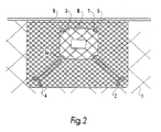
- FIG 2 shows a sensor module in the form of a trawl probe secured to a fishing trawl 1.
- a trawl probe is a sensor module which indicates in which area the catch is taking place by detecting entry of fish, trawl height, opening and bottom clearance.
- the trawl probe comprises a main body 3 arranged on the upper side of the trawl 1.
- the trawl probe is in a bag 2 made of a fine-meshed netting, and is secured to the head rope 6 in that the bag 2 and an attachment rope 5 are seized tightly to the head rope 6.
- the trawl probe 3 is fastened to the bag by rubber straps 4 and an attachment rope 5 and karabiners or snap hooks 7.
- the main body comprises fastening devices, in this case in the form of rings 3a for attachment to the trawl.
- the actual sensor device consists of a transducer 8 placed on the side of the trawl probe 3 facing towards the head rope.
- this sensor module is flattened and square, and is arranged in such manner that it rests against the trawl, or so that the distance between the trawl and the sensor module is small.
- the angular position of the area of the trawl lying in contact with or in the immediate vicinity of the sensor module can be assumed to be the same as the angular position of the sensor module main body.
- Figure 3 shows a sensor module according to the invention, equipped with devices for measuring angular position in three directions.
- the sensor module comprises a main body 3, optionally a sensor device (tension sensor, geophone etc, not shown) and fastening devices for attachment to the trawl (not shown).
- the main body 3 in this example is square and flattened and three directions can be defined in connection with the plane of the main body: a first direction z that is at right angles to the plane of the main body, and a second direction x and a third direction y at right angles to z and which are at right angles to each other.
- the sensor module according to the invention comprises a first inclinometer 10 which will measure changes in the position of the main body in the x direction.
- a second inclinometer 11 will, in a similar way, measure changes in the position of the main body in relation to the y direction, and a third inclinometer 12 will measure changes in the z direction.
- a sensor module could comprise one, two or three devices for measuring angular position depending on the location of the sensor module on the trawl, the geometry of the main body and the number/location of angle measuring devices in adjacent sensor modules.
- Figure 4 shows another embodiment of the sensor module according to the invention, this time in connection with a cylindrical main body.
- the sensor module of such shape is the net transponder, which is designed to indicate the position of the bottom rope.
- the net transponder comprises a cylindrical main body 3, fastening means 3a for attachment to the trawl (not shown) and a sensor device (not shown).
- the sensor module also comprises a device 11 for measuring the angular position of the main body 3 in the longitudinal direction x of the cylinder.
- the invention will comprise a main body having devices for measuring angular position, but it could also comprise a sensor device for measuring parameters associated with the fishing operation.
- the last-mentioned alternative will also include the case in which the sensor module comprises a sensor device and angular position measuring devices, but where the sensor device is not activated, so that the module is only used for measuring angular position.
- the invention also comprises a system for providing, on the basis of the measuring results, a representation of the position of the trawl.
- the accuracy of the representation will of course depend upon the number of angular position measuring devices and their location on the trawl.
- the system for charting the position of fishing gear according to the invention comprises:
Landscapes
- Life Sciences & Earth Sciences (AREA)
- Environmental Sciences (AREA)
- Animal Husbandry (AREA)
- Biodiversity & Conservation Biology (AREA)
- Length Measuring Devices With Unspecified Measuring Means (AREA)
- Toys (AREA)
- Gear Transmission (AREA)
- Mechanical Means For Catching Fish (AREA)
Applications Claiming Priority (3)
| Application Number | Priority Date | Filing Date | Title |
|---|---|---|---|
| NO20040708A NO326638B1 (no) | 2004-02-18 | 2004-02-18 | Sensormoduler for fiskeredskaper. |
| EP05722078A EP1715737B1 (de) | 2004-02-18 | 2005-02-18 | Anlage zur Standortsbestimmung eines Fischfanggerätes mit Sensormodulen |
| EP08004161A EP1922921A3 (de) | 2004-02-18 | 2005-02-18 | Sensormodule für Fischfanggerät |
Related Parent Applications (3)
| Application Number | Title | Priority Date | Filing Date |
|---|---|---|---|
| EP08004161A Division EP1922921A3 (de) | 2004-02-18 | 2005-02-18 | Sensormodule für Fischfanggerät |
| EP05722078.2 Division | 2005-02-18 | ||
| EP08004161.9 Division | 2008-03-06 |
Publications (2)
| Publication Number | Publication Date |
|---|---|
| EP2098114A2 true EP2098114A2 (de) | 2009-09-09 |
| EP2098114A3 EP2098114A3 (de) | 2011-04-20 |
Family
ID=34793433
Family Applications (3)
| Application Number | Title | Priority Date | Filing Date |
|---|---|---|---|
| EP08004161A Ceased EP1922921A3 (de) | 2004-02-18 | 2005-02-18 | Sensormodule für Fischfanggerät |
| EP09008382A Withdrawn EP2098114A3 (de) | 2004-02-18 | 2005-02-18 | Sensormodule für Fischfanggeräte |
| EP05722078A Revoked EP1715737B1 (de) | 2004-02-18 | 2005-02-18 | Anlage zur Standortsbestimmung eines Fischfanggerätes mit Sensormodulen |
Family Applications Before (1)
| Application Number | Title | Priority Date | Filing Date |
|---|---|---|---|
| EP08004161A Ceased EP1922921A3 (de) | 2004-02-18 | 2005-02-18 | Sensormodule für Fischfanggerät |
Family Applications After (1)
| Application Number | Title | Priority Date | Filing Date |
|---|---|---|---|
| EP05722078A Revoked EP1715737B1 (de) | 2004-02-18 | 2005-02-18 | Anlage zur Standortsbestimmung eines Fischfanggerätes mit Sensormodulen |
Country Status (7)
| Country | Link |
|---|---|
| EP (3) | EP1922921A3 (de) |
| AT (1) | ATE404052T1 (de) |
| DE (1) | DE602005008909D1 (de) |
| DK (1) | DK1715737T3 (de) |
| ES (1) | ES2308468T3 (de) |
| NO (1) | NO326638B1 (de) |
| WO (1) | WO2005077162A1 (de) |
Families Citing this family (7)
| Publication number | Priority date | Publication date | Assignee | Title |
|---|---|---|---|---|
| NO321070B1 (no) * | 2004-07-29 | 2006-03-13 | Henning Skjold-Larsen | Fremgangsmate og anordning for overvaking av posisjonen til et plategear |
| NO325356B1 (no) | 2006-08-08 | 2008-04-07 | Henning Skjold-Larsen | Vinkelbasert fyllingsgradindikator |
| EP2208417A1 (de) * | 2009-01-19 | 2010-07-21 | Henning Skjold-Larsen | Befestigungsvorrichtung für ein Sensormodul |
| NO334751B1 (no) * | 2011-09-22 | 2014-05-19 | Scantrawl As | System og fremgangsmåte for styring av trålfiske |
| US20150156998A1 (en) * | 2013-12-09 | 2015-06-11 | Smart Catch LLC | System, method, and platform for remote sensing and device manipulation in fishing environments |
| NO347510B1 (no) * | 2022-02-08 | 2023-12-04 | Scantrol Deep Vision As | Undervannssensor til bruk i en trål |
| EP4618752A1 (de) * | 2022-11-15 | 2025-09-24 | Caledonia Nets LLC | System zur messung der netzposition eines seine und verfahren zur bestimmung der netzposition eines seine |
Family Cites Families (4)
| Publication number | Priority date | Publication date | Assignee | Title |
|---|---|---|---|---|
| GB134969A (de) * | ||||
| GB1342969A (en) * | 1970-03-21 | 1974-01-10 | Morski Inst Rybacki | Method of continuously measuring a number of underwater parameters and simultaneously transmitting the measured parameters to a ship |
| PL68790B1 (de) * | 1970-05-27 | 1973-02-28 | ||
| DK161551C (da) * | 1988-04-28 | 1991-12-30 | Preben Munk Andersen | Apparat til overvaagning af vinkelstillingen mellem to wirer, fortrinsvis ved trawlovervaagning |
-
2004
- 2004-02-18 NO NO20040708A patent/NO326638B1/no active IP Right Review Request
-
2005
- 2005-02-18 DK DK05722078T patent/DK1715737T3/da active
- 2005-02-18 DE DE602005008909T patent/DE602005008909D1/de not_active Expired - Fee Related
- 2005-02-18 EP EP08004161A patent/EP1922921A3/de not_active Ceased
- 2005-02-18 EP EP09008382A patent/EP2098114A3/de not_active Withdrawn
- 2005-02-18 WO PCT/NO2005/000063 patent/WO2005077162A1/en not_active Ceased
- 2005-02-18 ES ES05722078T patent/ES2308468T3/es not_active Expired - Lifetime
- 2005-02-18 EP EP05722078A patent/EP1715737B1/de not_active Revoked
- 2005-02-18 AT AT05722078T patent/ATE404052T1/de not_active IP Right Cessation
Also Published As
| Publication number | Publication date |
|---|---|
| EP1922921A2 (de) | 2008-05-21 |
| WO2005077162A1 (en) | 2005-08-25 |
| NO20040708D0 (no) | 2004-02-18 |
| DE602005008909D1 (de) | 2008-09-25 |
| EP2098114A3 (de) | 2011-04-20 |
| NO20040708L (no) | 2005-08-19 |
| DK1715737T3 (da) | 2008-09-29 |
| EP1715737A1 (de) | 2006-11-02 |
| NO326638B1 (no) | 2009-01-26 |
| EP1922921A3 (de) | 2008-10-29 |
| EP1715737B1 (de) | 2008-08-13 |
| ATE404052T1 (de) | 2008-08-15 |
| ES2308468T3 (es) | 2008-12-01 |
Similar Documents
| Publication | Publication Date | Title |
|---|---|---|
| JP6812558B2 (ja) | 魚数計測装置、魚数計測システム及び魚数計測方法 | |
| ES2546953T3 (es) | Sistema de clasificación de peces para clasificar peces en una red de pesca de arrastre | |
| EP1715737B1 (de) | Anlage zur Standortsbestimmung eines Fischfanggerätes mit Sensormodulen | |
| US20060018197A1 (en) | Acoustic biomass monitor | |
| NO330863B1 (no) | Anordning og fremgangsmate for snittvektsmaling og appetittforing i oppdrettsanlegg | |
| US20140230308A1 (en) | System and method for screening fish during fishing | |
| WO2007105956A1 (en) | Electric field sensor for marine environments | |
| US9599736B2 (en) | Operation managing system for driving a navigation control device according to a degraded operating mode | |
| JP2011188806A (ja) | 水中における活魚の計数装置 | |
| JP3747308B2 (ja) | 魚槽内の活魚計測装置 | |
| ES2829562T3 (es) | Geometría de red de arrastre gemela | |
| JPS63116631A (ja) | トロール漁用装置並びにトロール漁のモニター方法 | |
| KR101488217B1 (ko) | 선체 장착형 단빔 음향측심기 및 확장가능한 바체크판을 구비한 측심시스템 | |
| KR20120058033A (ko) | 소하천용 수질 모니터링 장치 | |
| JP2005102638A (ja) | 水中における活魚の計数方法及びその装置 | |
| RU2008124201A (ru) | Устройство для индикации степени наполнения сети на основе угловых измерений | |
| WO2006011807A1 (en) | Method and device for position monitoring | |
| JP2004524022A (ja) | 海底において物体の物理的な着底を検出するための方法及び装置 | |
| ES2966606T3 (es) | Sensor para medir la flexión de un poste | |
| JP2002032733A (ja) | 活魚計数方法及びその装置 | |
| WO1999044057A1 (en) | Device and method for measuring the action potential of aquatic organisms | |
| WO2004044618A2 (en) | Floating weather station | |
| EP2150102A2 (de) | Vorrichtung zur erkennung einer wadennetzwand | |
| RU2303871C2 (ru) | Способ для мониторинга промысловой акватории | |
| CN207182591U (zh) | 一种水下电子围栏监控预警系统 |
Legal Events
| Date | Code | Title | Description |
|---|---|---|---|
| PUAI | Public reference made under article 153(3) epc to a published international application that has entered the european phase |
Free format text: ORIGINAL CODE: 0009012 |
|
| AC | Divisional application: reference to earlier application |
Ref document number: 1922921 Country of ref document: EP Kind code of ref document: P Ref document number: 1715737 Country of ref document: EP Kind code of ref document: P |
|
| AK | Designated contracting states |
Kind code of ref document: A2 Designated state(s): AT BE BG CH CY CZ DE DK EE ES FI FR GB GR HU IE IS IT LI LT LU MC NL PL PT RO SE SI SK TR |
|
| PUAL | Search report despatched |
Free format text: ORIGINAL CODE: 0009013 |
|
| AK | Designated contracting states |
Kind code of ref document: A3 Designated state(s): AT BE BG CH CY CZ DE DK EE ES FI FR GB GR HU IE IS IT LI LT LU MC NL PL PT RO SE SI SK TR |
|
| STAA | Information on the status of an ep patent application or granted ep patent |
Free format text: STATUS: THE APPLICATION IS DEEMED TO BE WITHDRAWN |
|
| 18D | Application deemed to be withdrawn |
Effective date: 20110901 |