EP2097680B1 - A cooking device - Google Patents
A cooking device Download PDFInfo
- Publication number
- EP2097680B1 EP2097680B1 EP07857569.3A EP07857569A EP2097680B1 EP 2097680 B1 EP2097680 B1 EP 2097680B1 EP 07857569 A EP07857569 A EP 07857569A EP 2097680 B1 EP2097680 B1 EP 2097680B1
- Authority
- EP
- European Patent Office
- Prior art keywords
- cook top
- frame
- cooking device
- front panel
- extension
- Prior art date
- Legal status (The legal status is an assumption and is not a legal conclusion. Google has not performed a legal analysis and makes no representation as to the accuracy of the status listed.)
- Active
Links
- 238000010411 cooking Methods 0.000 title claims description 30
- 238000003825 pressing Methods 0.000 claims description 20
- 210000001061 forehead Anatomy 0.000 claims description 9
- 238000005452 bending Methods 0.000 claims description 5
- 210000003298 dental enamel Anatomy 0.000 description 8
- 230000002238 attenuated effect Effects 0.000 description 4
- 238000005336 cracking Methods 0.000 description 4
- 238000004519 manufacturing process Methods 0.000 description 3
- 238000000034 method Methods 0.000 description 3
- 229910000831 Steel Inorganic materials 0.000 description 2
- 238000010438 heat treatment Methods 0.000 description 2
- 239000000463 material Substances 0.000 description 2
- 239000010959 steel Substances 0.000 description 2
- 239000002320 enamel (paints) Substances 0.000 description 1
- 210000003128 head Anatomy 0.000 description 1
- 238000007493 shaping process Methods 0.000 description 1
Images


Classifications
-
- F—MECHANICAL ENGINEERING; LIGHTING; HEATING; WEAPONS; BLASTING
- F24—HEATING; RANGES; VENTILATING
- F24C—DOMESTIC STOVES OR RANGES ; DETAILS OF DOMESTIC STOVES OR RANGES, OF GENERAL APPLICATION
- F24C15/00—Details
- F24C15/10—Tops, e.g. hot plates; Rings
-
- F—MECHANICAL ENGINEERING; LIGHTING; HEATING; WEAPONS; BLASTING
- F24—HEATING; RANGES; VENTILATING
- F24C—DOMESTIC STOVES OR RANGES ; DETAILS OF DOMESTIC STOVES OR RANGES, OF GENERAL APPLICATION
- F24C15/00—Details
- F24C15/08—Foundations or supports plates; Legs or pillars; Casings; Wheels
Definitions
- the present invention relates to a cooking device to which the cook top is mounted whereon cooking processes are performed.
- the cook top disposed on the top surface of cooking devices including burners thereon for performing the cooking process is produced of steel sheet and coated with enamel.
- the enamel coated cook top is being mounted on the frame, it can be subjected to tensions and impacts and this may result in damaging the enamel, which is a fragile material.
- connection springs are used to resiliently mount the cook top on the frame; however, enamel cracking cannot be avoided while mounting the cook top particularly on the frame.
- German Patent Document No DE19613320 a work surface fixing system used in household appliances is explained.
- the fixing system comprises a pair of spring sockets at opposite ends of the switch panel extending across the top front edge of the household appliance.
- the aim of the present invention is to the realization of a cooking device wherein the cook top can be mounted easily.
- the cook top is mounted by pressing down on the connection springs that are previously fastened to the upper surface of the frame which forms the skeleton of the body or to the front panel.
- the connection springs By means of the connection springs, the impacts that may affect the cook top during assembly or use are attenuated and thus the enamel coated on the cook top is prevented from cracking.
- connection spring comprises a fixing extension for assembling thereof to the frame and a resilient extension for attenuating the impacts by leaning on the bent side of the cook top, shaped as an inverted V, one arm of the V shape connected to the fixing extension and the other aim bearing on the front or lateral side of the cook top.
- the resilient extension comprises a continuous forehead surface that stretches the cook top backwards by the bent sides of the cook top pushing while the cook top is mounted by pressing downwards and a pressing extension that curves inwards by bending the forehead surface concavely that compresses the cook top by leaning on the side of the cook top seated on the frame or the front panel.
- a supporting protrusion is provided on the frame or the front panel that restricts the forwards, backwards motion of the connection spring and the connection spring is assembled by being seated on the supporting protrusion by means of a depression disposed on the fixing extension.
- a channel is arranged on the fixing extension and the connection spring is assembled on the frame allowing thereof to slide along the channel.
- a resilient extension is situated on the rear side of the connection spring and this extension increases stretching of the spring by leaning on a supporting protrusion arranged at the rear.
- stoppers are provided on the cook top that prevent the sideways movement of the cook top by leaning on the connection springs.
- the front side of the cook top is in the curved form and the connection springs are positioned angularly with respect to each other and in the vertical direction to the curved front side of the cook top such that the cook top is mounted on the frame by pressing down thereon.
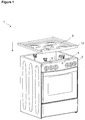
- the cooking device (1) comprises a body wherein the cooking process is performed on the upper surface and/or the interior volume, a front panel (2) including the elements such as knobs and displays thereon, a cook top (3) mounted on the body, containing the gas burners and/or electrical heating plates for heating and/or cooking and a frame (4) to which the walls forming the body, the front panel (2) and the cook top (3) are fastened ( Figures 1 , 2 ).
- the cook top (3) is produced by shaping the steel sheet material and coated with enamel.
- the cook top (3) comprises at least one side (12) formed by bending downwards the portions corresponding to above the front panel (2) and the frame (4) ( Figures 1 , 2 , 3 , 5 ).
- the cooking device (1) furthermore comprises a connection spring (5) that provides attaching the cook top (3), which is mounted to the frame, to the frame (4) to be resiliently and attenuating the forces acting on the cook top (3).
- the resilient extension (7) comprises an continuous forehead surface (A) disposed on the front side thereof over which the side (12) slides and pushes backwards while the cook top (3) is mounted by pressing down and a pressing extension (B) that curves inwardly by bending the forehead surface (A) concavely which compresses the cook top (3) by leaning on the inside of the side (12) seated on the frame (4) ( Figure 4 ).
- the continuous form of the forehead surface (A) provides the stretching of the resilient extension (7).
- connection spring (5) is fixed to the front panel (2) or the frame (4) by means of the fixing extension (6).
- the cook top (3) is brought over the frame (4) and after the burner head openings on the cook top (3) are aligned with the burners, the cook top (3) is lowered to be seated on the frame (4) ( Figures 1 , 2 ).
- the rear side of the cook top (3) is fixed by fastening elements such as screws or the like.
- the front and lateral sides (12) of the cook top (3) are bent downwards.
- the front or the lateral side (12) slides on the forehead surface (A) of the resilient extension (7) in front of the connection spring (5) and stretches the resilient extension (7) backwards and after passing beyond the forehead surface (A) goes under the pressing extension (B). Assembling is completed by compressing the side (12) between the pressing extension (B) and the frame (4) or the upper surface of the front panel (2).
- the resilient extension (7) does not stretch easily since the spring constant is high, only stretches under excessive forces, preventing cracking of the enamel coating of the cook top (3).
- the cooking device (1) comprises a supporting protrusion (8) disposed on the frame (4) or the front panel (2) that restricts the forwards, backwards motion of the connection spring (5) ( Figure 5 ).
- the motion of the connection spring (5) in the forwards, backwards directions is restricted by fixing on the supporting protrusion (8) or by bearing on the supporting protrusion (8), the movement of the cook top (3) in the forwards, backwards directions is attenuated only by the stretching of the resilient extension (7).
- connection spring (5) comprises a depression (9) for assembling thereof by being seated on the supporting protrusion (8), disposed on the fixing extension (6) and formed preferably by bending the fixing extension (6) ( Figures 4, 5 ).
- connection spring (5) comprises a channel (10) arranged on the fixing extension (6) for assembling thereof on the frame (4) by allowing to slide along a certain distance ( Figure 6 ).
- the connection spring (5) is attached to the frame (4) or the front panel (2) by a fastening element such as a screw, pin etc. that can move inside the channel (10) formed on the fixing extension (6) and attenuates the movement of the cook top (3) in the forwards, backwards directions by means of the channel (10) and also by the stretching feature of the resilient extension (7).
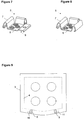
- the cooking device (1) comprises one or more stoppers (11) situated on the cook top (3) that prevent the sideways movement of the cook top (3) by contacting to the connection spring (5) from the side ( Figure 9 ).
- the cooking device (1) comprises a cook top (3), the front side configured to be curved that is mounted on connection springs (5) by pressing down and connection springs (5) fixed on the frame (4) or the front panel (2), positioned angularly with respect to each other and in the vertical direction to the curved front side of the cook top (3) such that the cook top (3) is mounted on the frame (4) by pressing downwards ( Figure 9 ).
- connection spring (5) furthermore comprises additional resilient elements that extend along the rear and lateral sides thereof that increase the attenuation of impacts acting on the cook top (3) ( Figures 7, 8 ).
- additional resilient elements that extend along the rear and lateral sides thereof that increase the attenuation of impacts acting on the cook top (3) ( Figures 7, 8 ).
- the movement of the cook top (3) both in the forwards, backwards and right and left directions is attenuated by means of the additional resilient elements.
- the enamel coated cook top (3) is mounted on the frame (4) or the front panel (2), the impacts acting thereon are attenuated by means of the connection springs (5) and cracking hence damaging of the enamel is prevented.
- the front side curved cook top (3) is mounted easily by pressing down and fitting to the connection springs (5), moreover since the cook top (3) is mounted from the top by aligning the burner openings thereon with the burners, the cook top (3) is prevented from bumping to the burners and being damaged during assembling.
Description
- The present invention relates to a cooking device to which the cook top is mounted whereon cooking processes are performed.
- The cook top disposed on the top surface of cooking devices including burners thereon for performing the cooking process is produced of steel sheet and coated with enamel. During production, while the enamel coated cook top is being mounted on the frame, it can be subjected to tensions and impacts and this may result in damaging the enamel, which is a fragile material. In state of the art, connection springs are used to resiliently mount the cook top on the frame; however, enamel cracking cannot be avoided while mounting the cook top particularly on the frame.
- In state of the art German Patent Document No
DE19613320 , a work surface fixing system used in household appliances is explained. The fixing system comprises a pair of spring sockets at opposite ends of the switch panel extending across the top front edge of the household appliance. - In document
GB 430 829 A - The aim of the present invention is to the realization of a cooking device wherein the cook top can be mounted easily.
- The cooking device realized in order to attain the aim of the present invention is explicated in the claims.
- While the cooking device of the present invention is manufactured, the cook top is mounted by pressing down on the connection springs that are previously fastened to the upper surface of the frame which forms the skeleton of the body or to the front panel. By means of the connection springs, the impacts that may affect the cook top during assembly or use are attenuated and thus the enamel coated on the cook top is prevented from cracking.
- The connection spring comprises a fixing extension for assembling thereof to the frame and a resilient extension for attenuating the impacts by leaning on the bent side of the cook top, shaped as an inverted V, one arm of the V shape connected to the fixing extension and the other aim bearing on the front or lateral side of the cook top. The resilient extension comprises a continuous forehead surface that stretches the cook top backwards by the bent sides of the cook top pushing while the cook top is mounted by pressing downwards and a pressing extension that curves inwards by bending the forehead surface concavely that compresses the cook top by leaning on the side of the cook top seated on the frame or the front panel.
- In an embodiment of the present invention, a supporting protrusion is provided on the frame or the front panel that restricts the forwards, backwards motion of the connection spring and the connection spring is assembled by being seated on the supporting protrusion by means of a depression disposed on the fixing extension.
- In another embodiment of the present invention, a channel is arranged on the fixing extension and the connection spring is assembled on the frame allowing thereof to slide along the channel.
- In another embodiment of the present invention, a resilient extension is situated on the rear side of the connection spring and this extension increases stretching of the spring by leaning on a supporting protrusion arranged at the rear.
- In another embodiment of the present invention, stoppers are provided on the cook top that prevent the sideways movement of the cook top by leaning on the connection springs.
- In another embodiment of the present invention, the front side of the cook top is in the curved form and the connection springs are positioned angularly with respect to each other and in the vertical direction to the curved front side of the cook top such that the cook top is mounted on the frame by pressing down thereon.
- The cooking device realized in order to attain the aim of the present invention is illustrated in the attached figures, where:
-
Figure 1 - is the perspective view of a cooking device body and a cook top. -
Figure 2 - is the perspective view of a cooking device after the cook top is mounted thereon. -
Figure 3 - is the view of detail D inFigure 2 . -
Figure 4 - is the perspective view of a connection spring. -
Figure 5 - is the cross-sectional view of a connection spring. -
Figure 6 - is the perspective view of a connection spring including a channel at the center. -
Figures 7, 8 - are the perspective views of connection springs including additional resilient elements. -
Figure 9 - is the schematic view of a cook top with a curved front side and the connection springs positioned angularly with respect to one another. - The elements illustrated in the figures are numbered as follows:
- 1. Cooking device
- 2. Front panel
- 3. Cook top
- 4. Frame
- 5. Connection spring
- 6. Fixing extension
- 7. Resilient extension
- 8. Supporting protrusion
- 9. Depression
- 10. Channel
- 11. Stopper
- 12. Side
- The cooking device (1) comprises a body wherein the cooking process is performed on the upper surface and/or the interior volume, a front panel (2) including the elements such as knobs and displays thereon, a cook top (3) mounted on the body, containing the gas burners and/or electrical heating plates for heating and/or cooking and a frame (4) to which the walls forming the body, the front panel (2) and the cook top (3) are fastened (
Figures 1 ,2 ). - The cook top (3) is produced by shaping the steel sheet material and coated with enamel. The cook top (3) comprises at least one side (12) formed by bending downwards the portions corresponding to above the front panel (2) and the frame (4) (
Figures 1 ,2 ,3 ,5 ). - The cooking device (1) furthermore comprises a connection spring (5) that provides attaching the cook top (3), which is mounted to the frame, to the frame (4) to be resiliently and attenuating the forces acting on the cook top (3).
- The connection spring (5), enabling to attach the cook top (3) on the frame (4) by pressing down, used in the cooking device (1) of the present invention comprises
- a fixing extension (6) for mounting on the frame (4) or the front panel (2) by screwing etc.,
- a resilient extension (7) shaped as an inverted V, one arm of the V shape connected to one end of the fixing extension (6) and the other arm leaning on the side (12), that stretches backwards by the side (12) of the cook top (3) pushing while the cook top (3) is mounted by pressing down, that returns to its former position when the cook top (3) is properly seated on the frame (4) and exerting force on the side (12) from the inside so that the cook top (3) is attached on the frame (4) by pressing down (
Figures 4, 5 ). - The resilient extension (7) comprises an continuous forehead surface (A) disposed on the front side thereof over which the side (12) slides and pushes backwards while the cook top (3) is mounted by pressing down and a pressing extension (B) that curves inwardly by bending the forehead surface (A) concavely which compresses the cook top (3) by leaning on the inside of the side (12) seated on the frame (4) (
Figure 4 ). The continuous form of the forehead surface (A) provides the stretching of the resilient extension (7). - During the production of the cooking device (1), the connection spring (5) is fixed to the front panel (2) or the frame (4) by means of the fixing extension (6). The cook top (3) is brought over the frame (4) and after the burner head openings on the cook top (3) are aligned with the burners, the cook top (3) is lowered to be seated on the frame (4) (
Figures 1 ,2 ). The rear side of the cook top (3) is fixed by fastening elements such as screws or the like. The front and lateral sides (12) of the cook top (3) are bent downwards. The front or the lateral side (12) slides on the forehead surface (A) of the resilient extension (7) in front of the connection spring (5) and stretches the resilient extension (7) backwards and after passing beyond the forehead surface (A) goes under the pressing extension (B). Assembling is completed by compressing the side (12) between the pressing extension (B) and the frame (4) or the upper surface of the front panel (2). The resilient extension (7) does not stretch easily since the spring constant is high, only stretches under excessive forces, preventing cracking of the enamel coating of the cook top (3). - In an embodiment of the present invention, the cooking device (1) comprises a supporting protrusion (8) disposed on the frame (4) or the front panel (2) that restricts the forwards, backwards motion of the connection spring (5) (
Figure 5 ). The motion of the connection spring (5) in the forwards, backwards directions is restricted by fixing on the supporting protrusion (8) or by bearing on the supporting protrusion (8), the movement of the cook top (3) in the forwards, backwards directions is attenuated only by the stretching of the resilient extension (7). - In another embodiment of the present invention, the connection spring (5) comprises a depression (9) for assembling thereof by being seated on the supporting protrusion (8), disposed on the fixing extension (6) and formed preferably by bending the fixing extension (6) (
Figures 4, 5 ). - In another embodiment of the present invention, the connection spring (5) comprises a channel (10) arranged on the fixing extension (6) for assembling thereof on the frame (4) by allowing to slide along a certain distance (
Figure 6 ). The connection spring (5) is attached to the frame (4) or the front panel (2) by a fastening element such as a screw, pin etc. that can move inside the channel (10) formed on the fixing extension (6) and attenuates the movement of the cook top (3) in the forwards, backwards directions by means of the channel (10) and also by the stretching feature of the resilient extension (7). - In an embodiment of the present invention, the cooking device (1) comprises one or more stoppers (11) situated on the cook top (3) that prevent the sideways movement of the cook top (3) by contacting to the connection spring (5) from the side (
Figure 9 ). - In an embodiment of the present invention, the cooking device (1) comprises a cook top (3), the front side configured to be curved that is mounted on connection springs (5) by pressing down and connection springs (5) fixed on the frame (4) or the front panel (2), positioned angularly with respect to each other and in the vertical direction to the curved front side of the cook top (3) such that the cook top (3) is mounted on the frame (4) by pressing downwards (
Figure 9 ). - The connection spring (5) furthermore comprises additional resilient elements that extend along the rear and lateral sides thereof that increase the attenuation of impacts acting on the cook top (3) (
Figures 7, 8 ). The movement of the cook top (3) both in the forwards, backwards and right and left directions is attenuated by means of the additional resilient elements. - During the production of the cooking device (1) of the present invention, while the enamel coated cook top (3) is mounted on the frame (4) or the front panel (2), the impacts acting thereon are attenuated by means of the connection springs (5) and cracking hence damaging of the enamel is prevented. The front side curved cook top (3) is mounted easily by pressing down and fitting to the connection springs (5), moreover since the cook top (3) is mounted from the top by aligning the burner openings thereon with the burners, the cook top (3) is prevented from bumping to the burners and being damaged during assembling.
Claims (7)
- A cooking device (1) comprising walls, forming a body, a front panel (2) including elements in particular knobs and displays thereon, a cook top (3) mounted on the body and having at least one side (12) bent downwards, and a frame (4) to which the walls, the front panel (2) and the cook top (3) are fastened, and the at least one side (12) bent downwards having a portion placed above the front panel (2) and/or the frame (4) characterized in that the cooking device further comprises a connection spring (5)- for attaching the cook top (3) on the frame (4) by pressing down,- having a fixing extension (6) for mounting on the frame (4) or the front panel (2), and- a resilient extension (7) shaped as an inverted V, one arm of the V shape connected to one end of the fixing extension (6) and the other arm leaning on said portion of the side (12) placed above the front panel (2) and/or the frame (4) so that it is stretched backwards by the at least one side (12) of the cook top (3) while the cook top (3) is mounted by pressing down, and so that it returns to its former position when the cook top (3) is properly seated on the frame (4), thus exerting force on the side (12) from the inside.
- A cooking device (1) as in Claim 1, characterized by the connection spring (5) comprising the resilient extension (7) having a continuous forehead surface (A) disposed on the front side thereof over which the at least one side (12) slides and pushes backwards while the cook top (3) is mounted by pressing down and a pressing extension (B) that curves inwardly by bending the forehead surface (A) concavely which compresses the cook top (3) by leaning on the inside of the at least one side (12) seated on the frame (4).
- A cooking device (1) as in Claim 1, characterized by a supporting protrusion (8) disposed on the frame (4) or the front panel (2) that restricts the movement of the connection spring (5) in the forward and backward directions.
- A cooking device (1) as in Claim 3, characterized by the connection spring (5) comprising a depression (9) disposed on the fixing extension (6) for assembling thereof by being seated on the supporting protrusion (8).
- A cooking device (1) as in Claim 1, characterized by the connection spring (5) comprising a channel (10) arranged on the fixing extension (6) for assembling thereof on the frame (4) by allowing to slide along a certain distance.
- A cooking device (1) as in any one of the above claims, characterized by one or more stoppers (11) situated on the cook top (3) that prevent the sideways movement of the cook top (3) by contacting to the connection spring (5) from the side.
- A cooking device (1) as in any one of the above claims, characterized by the cook top (3), the front side configured to be curved, that is mounted on the connection springs (5) by pressing down and the connection springs (5) fixed on the frame (4) or the front panel (2), positioned angularly with respect to each other and in the vertical direction to the curved front side of the cook top (3) such that the cook top (3) is mounted on the frame (4) by pressing downwards.
Priority Applications (1)
| Application Number | Priority Date | Filing Date | Title |
|---|---|---|---|
| PL07857569T PL2097680T3 (en) | 2006-12-28 | 2007-12-14 | A cooking device |
Applications Claiming Priority (2)
| Application Number | Priority Date | Filing Date | Title |
|---|---|---|---|
| TR200607581 | 2006-12-28 | ||
| PCT/EP2007/063922 WO2008080795A2 (en) | 2006-12-28 | 2007-12-14 | A cooking device |
Publications (2)
| Publication Number | Publication Date |
|---|---|
| EP2097680A2 EP2097680A2 (en) | 2009-09-09 |
| EP2097680B1 true EP2097680B1 (en) | 2016-02-10 |
Family
ID=39589028
Family Applications (1)
| Application Number | Title | Priority Date | Filing Date |
|---|---|---|---|
| EP07857569.3A Active EP2097680B1 (en) | 2006-12-28 | 2007-12-14 | A cooking device |
Country Status (4)
| Country | Link |
|---|---|
| EP (1) | EP2097680B1 (en) |
| ES (1) | ES2568684T3 (en) |
| PL (1) | PL2097680T3 (en) |
| WO (1) | WO2008080795A2 (en) |
Cited By (3)
| Publication number | Priority date | Publication date | Assignee | Title |
|---|---|---|---|---|
| WO2018063115A2 (en) | 2016-07-22 | 2018-04-05 | Femaş Metal Sanayi̇ Ve Ti̇caret Anoni̇m Şi̇rketi̇ | Flexible fitting mechanism in cooking devices |
| WO2019096488A1 (en) | 2017-11-17 | 2019-05-23 | Arcelik Anonim Sirketi | Cooker device with improved upper plate assembly |
| US10816217B2 (en) | 2018-01-26 | 2020-10-27 | Haier Us Appliance Solutions, Inc. | Oven appliance |
Families Citing this family (5)
| Publication number | Priority date | Publication date | Assignee | Title |
|---|---|---|---|---|
| ES2373152B1 (en) * | 2008-11-26 | 2012-12-10 | Bsh Electrodomésticos España, S.A. | COOKING FIELD AND PROCEDURE FOR THE MANUFACTURE OF A COOKING FIELD. |
| RU2615537C2 (en) | 2011-12-20 | 2017-04-05 | Бсх Хаусгерете Гмбх | Kitchen appliance with spring element |
| CN105612389A (en) * | 2013-09-18 | 2016-05-25 | 阿塞里克股份有限公司 | A cooker comprising a cast iron burner plate |
| ES2564314B1 (en) | 2014-08-20 | 2016-12-28 | Domingo Panea Medina | DOUBLE DISCHARGE TANK FOR TOILETS |
| WO2020136254A1 (en) | 2018-12-27 | 2020-07-02 | Arcelik Anonim Sirketi | A cooking device |
Family Cites Families (6)
| Publication number | Priority date | Publication date | Assignee | Title |
|---|---|---|---|---|
| GB430829A (en) * | 1934-01-09 | 1935-06-26 | Falk Stadelmann And Company Lt | Improvements in cooking apparatus |
| DE9108044U1 (en) * | 1991-06-29 | 1992-07-23 | Licentia Patent-Verwaltungs-Gmbh, 6000 Frankfurt, De | |
| US5549098A (en) * | 1994-02-16 | 1996-08-27 | Maytag Corporation | Glass range top-seal system |
| DE4434821C2 (en) * | 1994-09-29 | 1997-12-11 | Schott Glaswerke | Arrangement for mounting and holding a built-in hob |
| DE19613320C1 (en) * | 1996-04-03 | 1997-04-30 | Bauknecht Hausgeraete | Worksurface fixing system for domestic electrical appliance |
| DE102006003319B4 (en) * | 2006-01-23 | 2008-01-03 | Electrolux Home Products Corporation N.V. | Fastening element for fastening a component to a carrier element |
-
2007
- 2007-12-14 PL PL07857569T patent/PL2097680T3/en unknown
- 2007-12-14 WO PCT/EP2007/063922 patent/WO2008080795A2/en active Application Filing
- 2007-12-14 EP EP07857569.3A patent/EP2097680B1/en active Active
- 2007-12-14 ES ES07857569.3T patent/ES2568684T3/en active Active
Cited By (3)
| Publication number | Priority date | Publication date | Assignee | Title |
|---|---|---|---|---|
| WO2018063115A2 (en) | 2016-07-22 | 2018-04-05 | Femaş Metal Sanayi̇ Ve Ti̇caret Anoni̇m Şi̇rketi̇ | Flexible fitting mechanism in cooking devices |
| WO2019096488A1 (en) | 2017-11-17 | 2019-05-23 | Arcelik Anonim Sirketi | Cooker device with improved upper plate assembly |
| US10816217B2 (en) | 2018-01-26 | 2020-10-27 | Haier Us Appliance Solutions, Inc. | Oven appliance |
Also Published As
| Publication number | Publication date |
|---|---|
| WO2008080795A3 (en) | 2009-03-19 |
| WO2008080795A2 (en) | 2008-07-10 |
| PL2097680T3 (en) | 2016-08-31 |
| EP2097680A2 (en) | 2009-09-09 |
| ES2568684T3 (en) | 2016-05-03 |
Similar Documents
| Publication | Publication Date | Title |
|---|---|---|
| EP2097680B1 (en) | A cooking device | |
| EP2144009A1 (en) | A one-piece fastening element for a cooking hob and a cooking hob with one-piece fastening elements | |
| KR100771628B1 (en) | Electricity oven | |
| US9217573B2 (en) | Cook top unit for cooker | |
| EP3710754B1 (en) | Cooker device with improved upper plate assembly | |
| KR100767694B1 (en) | Electricity oven | |
| EP3047213B1 (en) | A cooker comprising a cast iron burner plate | |
| WO2011098289A1 (en) | A control panel for a household appliance | |
| WO1998041059A2 (en) | Spider mounting in a heating device | |
| KR20060014789A (en) | Mounting structure of heating element | |
| CN208658816U (en) | The shell shade assembly of cooking apparatus and cooking apparatus | |
| WO2008080960A2 (en) | A cooking range | |
| EP4235036A1 (en) | A cooking device comprising a mounting bracket | |
| JP5013977B2 (en) | Built-in cooking device | |
| CN218096090U (en) | Kitchen range chassis structure and gas kitchen range | |
| CN205682986U (en) | Toaster switch | |
| CN210040062U (en) | Multi-gear temperature controller and electric oven | |
| CN218096085U (en) | Kitchen range chassis structure and gas kitchen range | |
| CN219813855U (en) | Heating device and cooking utensil | |
| EP3903034B1 (en) | A cooking device | |
| CN219283409U (en) | Kitchen range chassis adjusting device and kitchen range | |
| US4368378A (en) | Electric heating elements | |
| CN215765223U (en) | Cooking utensils with switching support | |
| CN213721492U (en) | Baking oven | |
| CN210961678U (en) | Handheld cooking machine switch structure |
Legal Events
| Date | Code | Title | Description |
|---|---|---|---|
| PUAI | Public reference made under article 153(3) epc to a published international application that has entered the european phase |
Free format text: ORIGINAL CODE: 0009012 |
|
| 17P | Request for examination filed |
Effective date: 20090622 |
|
| AK | Designated contracting states |
Kind code of ref document: A2 Designated state(s): AT BE BG CH CY CZ DE DK EE ES FI FR GB GR HU IE IS IT LI LT LU LV MC MT NL PL PT RO SE SI SK TR |
|
| DAX | Request for extension of the european patent (deleted) | ||
| 17Q | First examination report despatched |
Effective date: 20130701 |
|
| GRAP | Despatch of communication of intention to grant a patent |
Free format text: ORIGINAL CODE: EPIDOSNIGR1 |
|
| INTG | Intention to grant announced |
Effective date: 20150922 |
|
| GRAS | Grant fee paid |
Free format text: ORIGINAL CODE: EPIDOSNIGR3 |
|
| GRAA | (expected) grant |
Free format text: ORIGINAL CODE: 0009210 |
|
| AK | Designated contracting states |
Kind code of ref document: B1 Designated state(s): AT BE BG CH CY CZ DE DK EE ES FI FR GB GR HU IE IS IT LI LT LU LV MC MT NL PL PT RO SE SI SK TR |
|
| REG | Reference to a national code |
Ref country code: GB Ref legal event code: FG4D |
|
| REG | Reference to a national code |
Ref country code: AT Ref legal event code: REF Ref document number: 774847 Country of ref document: AT Kind code of ref document: T Effective date: 20160215 Ref country code: CH Ref legal event code: EP |
|
| REG | Reference to a national code |
Ref country code: IE Ref legal event code: FG4D |
|
| REG | Reference to a national code |
Ref country code: DE Ref legal event code: R096 Ref document number: 602007044835 Country of ref document: DE |
|
| REG | Reference to a national code |
Ref country code: RO Ref legal event code: EPE |
|
| REG | Reference to a national code |
Ref country code: ES Ref legal event code: FG2A Ref document number: 2568684 Country of ref document: ES Kind code of ref document: T3 Effective date: 20160503 |
|
| REG | Reference to a national code |
Ref country code: LT Ref legal event code: MG4D |
|
| REG | Reference to a national code |
Ref country code: NL Ref legal event code: MP Effective date: 20160210 |
|
| REG | Reference to a national code |
Ref country code: AT Ref legal event code: MK05 Ref document number: 774847 Country of ref document: AT Kind code of ref document: T Effective date: 20160210 |
|
| PG25 | Lapsed in a contracting state [announced via postgrant information from national office to epo] |
Ref country code: FI Free format text: LAPSE BECAUSE OF FAILURE TO SUBMIT A TRANSLATION OF THE DESCRIPTION OR TO PAY THE FEE WITHIN THE PRESCRIBED TIME-LIMIT Effective date: 20160210 Ref country code: GR Free format text: LAPSE BECAUSE OF FAILURE TO SUBMIT A TRANSLATION OF THE DESCRIPTION OR TO PAY THE FEE WITHIN THE PRESCRIBED TIME-LIMIT Effective date: 20160511 |
|
| PG25 | Lapsed in a contracting state [announced via postgrant information from national office to epo] |
Ref country code: NL Free format text: LAPSE BECAUSE OF FAILURE TO SUBMIT A TRANSLATION OF THE DESCRIPTION OR TO PAY THE FEE WITHIN THE PRESCRIBED TIME-LIMIT Effective date: 20160210 Ref country code: PT Free format text: LAPSE BECAUSE OF FAILURE TO SUBMIT A TRANSLATION OF THE DESCRIPTION OR TO PAY THE FEE WITHIN THE PRESCRIBED TIME-LIMIT Effective date: 20160613 Ref country code: LV Free format text: LAPSE BECAUSE OF FAILURE TO SUBMIT A TRANSLATION OF THE DESCRIPTION OR TO PAY THE FEE WITHIN THE PRESCRIBED TIME-LIMIT Effective date: 20160210 Ref country code: SE Free format text: LAPSE BECAUSE OF FAILURE TO SUBMIT A TRANSLATION OF THE DESCRIPTION OR TO PAY THE FEE WITHIN THE PRESCRIBED TIME-LIMIT Effective date: 20160210 Ref country code: LT Free format text: LAPSE BECAUSE OF FAILURE TO SUBMIT A TRANSLATION OF THE DESCRIPTION OR TO PAY THE FEE WITHIN THE PRESCRIBED TIME-LIMIT Effective date: 20160210 Ref country code: AT Free format text: LAPSE BECAUSE OF FAILURE TO SUBMIT A TRANSLATION OF THE DESCRIPTION OR TO PAY THE FEE WITHIN THE PRESCRIBED TIME-LIMIT Effective date: 20160210 Ref country code: IS Free format text: LAPSE BECAUSE OF FAILURE TO SUBMIT A TRANSLATION OF THE DESCRIPTION OR TO PAY THE FEE WITHIN THE PRESCRIBED TIME-LIMIT Effective date: 20160610 |
|
| PG25 | Lapsed in a contracting state [announced via postgrant information from national office to epo] |
Ref country code: EE Free format text: LAPSE BECAUSE OF FAILURE TO SUBMIT A TRANSLATION OF THE DESCRIPTION OR TO PAY THE FEE WITHIN THE PRESCRIBED TIME-LIMIT Effective date: 20160210 Ref country code: DK Free format text: LAPSE BECAUSE OF FAILURE TO SUBMIT A TRANSLATION OF THE DESCRIPTION OR TO PAY THE FEE WITHIN THE PRESCRIBED TIME-LIMIT Effective date: 20160210 |
|
| REG | Reference to a national code |
Ref country code: DE Ref legal event code: R097 Ref document number: 602007044835 Country of ref document: DE |
|
| PG25 | Lapsed in a contracting state [announced via postgrant information from national office to epo] |
Ref country code: CZ Free format text: LAPSE BECAUSE OF FAILURE TO SUBMIT A TRANSLATION OF THE DESCRIPTION OR TO PAY THE FEE WITHIN THE PRESCRIBED TIME-LIMIT Effective date: 20160210 Ref country code: SK Free format text: LAPSE BECAUSE OF FAILURE TO SUBMIT A TRANSLATION OF THE DESCRIPTION OR TO PAY THE FEE WITHIN THE PRESCRIBED TIME-LIMIT Effective date: 20160210 |
|
| PLBE | No opposition filed within time limit |
Free format text: ORIGINAL CODE: 0009261 |
|
| STAA | Information on the status of an ep patent application or granted ep patent |
Free format text: STATUS: NO OPPOSITION FILED WITHIN TIME LIMIT |
|
| REG | Reference to a national code |
Ref country code: FR Ref legal event code: PLFP Year of fee payment: 10 |
|
| PG25 | Lapsed in a contracting state [announced via postgrant information from national office to epo] |
Ref country code: BE Free format text: LAPSE BECAUSE OF FAILURE TO SUBMIT A TRANSLATION OF THE DESCRIPTION OR TO PAY THE FEE WITHIN THE PRESCRIBED TIME-LIMIT Effective date: 20160210 |
|
| 26N | No opposition filed |
Effective date: 20161111 |
|
| PG25 | Lapsed in a contracting state [announced via postgrant information from national office to epo] |
Ref country code: SI Free format text: LAPSE BECAUSE OF FAILURE TO SUBMIT A TRANSLATION OF THE DESCRIPTION OR TO PAY THE FEE WITHIN THE PRESCRIBED TIME-LIMIT Effective date: 20160210 Ref country code: BG Free format text: LAPSE BECAUSE OF FAILURE TO SUBMIT A TRANSLATION OF THE DESCRIPTION OR TO PAY THE FEE WITHIN THE PRESCRIBED TIME-LIMIT Effective date: 20160510 |
|
| PGFP | Annual fee paid to national office [announced via postgrant information from national office to epo] |
Ref country code: PL Payment date: 20161213 Year of fee payment: 10 Ref country code: FR Payment date: 20161222 Year of fee payment: 10 Ref country code: RO Payment date: 20161212 Year of fee payment: 10 Ref country code: ES Payment date: 20161213 Year of fee payment: 10 |
|
| PGFP | Annual fee paid to national office [announced via postgrant information from national office to epo] |
Ref country code: IT Payment date: 20161223 Year of fee payment: 10 |
|
| REG | Reference to a national code |
Ref country code: CH Ref legal event code: PL |
|
| PG25 | Lapsed in a contracting state [announced via postgrant information from national office to epo] |
Ref country code: MC Free format text: LAPSE BECAUSE OF FAILURE TO SUBMIT A TRANSLATION OF THE DESCRIPTION OR TO PAY THE FEE WITHIN THE PRESCRIBED TIME-LIMIT Effective date: 20160210 |
|
| REG | Reference to a national code |
Ref country code: IE Ref legal event code: MM4A |
|
| PG25 | Lapsed in a contracting state [announced via postgrant information from national office to epo] |
Ref country code: LI Free format text: LAPSE BECAUSE OF NON-PAYMENT OF DUE FEES Effective date: 20161231 Ref country code: CH Free format text: LAPSE BECAUSE OF NON-PAYMENT OF DUE FEES Effective date: 20161231 Ref country code: LU Free format text: LAPSE BECAUSE OF NON-PAYMENT OF DUE FEES Effective date: 20161214 |
|
| PG25 | Lapsed in a contracting state [announced via postgrant information from national office to epo] |
Ref country code: IE Free format text: LAPSE BECAUSE OF NON-PAYMENT OF DUE FEES Effective date: 20161214 |
|
| PG25 | Lapsed in a contracting state [announced via postgrant information from national office to epo] |
Ref country code: CY Free format text: LAPSE BECAUSE OF FAILURE TO SUBMIT A TRANSLATION OF THE DESCRIPTION OR TO PAY THE FEE WITHIN THE PRESCRIBED TIME-LIMIT Effective date: 20160210 Ref country code: HU Free format text: LAPSE BECAUSE OF FAILURE TO SUBMIT A TRANSLATION OF THE DESCRIPTION OR TO PAY THE FEE WITHIN THE PRESCRIBED TIME-LIMIT; INVALID AB INITIO Effective date: 20071214 |
|
| PG25 | Lapsed in a contracting state [announced via postgrant information from national office to epo] |
Ref country code: RO Free format text: LAPSE BECAUSE OF NON-PAYMENT OF DUE FEES Effective date: 20171214 |
|
| PG25 | Lapsed in a contracting state [announced via postgrant information from national office to epo] |
Ref country code: MT Free format text: LAPSE BECAUSE OF NON-PAYMENT OF DUE FEES Effective date: 20161214 |
|
| REG | Reference to a national code |
Ref country code: FR Ref legal event code: ST Effective date: 20180831 |
|
| PG25 | Lapsed in a contracting state [announced via postgrant information from national office to epo] |
Ref country code: IT Free format text: LAPSE BECAUSE OF NON-PAYMENT OF DUE FEES Effective date: 20171214 Ref country code: FR Free format text: LAPSE BECAUSE OF NON-PAYMENT OF DUE FEES Effective date: 20180102 |
|
| PG25 | Lapsed in a contracting state [announced via postgrant information from national office to epo] |
Ref country code: PL Free format text: LAPSE BECAUSE OF NON-PAYMENT OF DUE FEES Effective date: 20171214 |
|
| REG | Reference to a national code |
Ref country code: ES Ref legal event code: FD2A Effective date: 20190703 |
|
| PG25 | Lapsed in a contracting state [announced via postgrant information from national office to epo] |
Ref country code: ES Free format text: LAPSE BECAUSE OF NON-PAYMENT OF DUE FEES Effective date: 20171215 |
|
| PGFP | Annual fee paid to national office [announced via postgrant information from national office to epo] |
Ref country code: GB Payment date: 20231220 Year of fee payment: 17 |
|
| PGFP | Annual fee paid to national office [announced via postgrant information from national office to epo] |
Ref country code: TR Payment date: 20231124 Year of fee payment: 17 Ref country code: DE Payment date: 20231214 Year of fee payment: 17 |