EP2096966B1 - Anziehvorrichtung für strumpfwaren, im besonderen für kompressionsstrümpfe - Google Patents
Anziehvorrichtung für strumpfwaren, im besonderen für kompressionsstrümpfe Download PDFInfo
- Publication number
- EP2096966B1 EP2096966B1 EP07859189A EP07859189A EP2096966B1 EP 2096966 B1 EP2096966 B1 EP 2096966B1 EP 07859189 A EP07859189 A EP 07859189A EP 07859189 A EP07859189 A EP 07859189A EP 2096966 B1 EP2096966 B1 EP 2096966B1
- Authority
- EP
- European Patent Office
- Prior art keywords
- hosiery
- foot
- handle
- support
- saddle
- Prior art date
- Legal status (The legal status is an assumption and is not a legal conclusion. Google has not performed a legal analysis and makes no representation as to the accuracy of the status listed.)
- Ceased
Links
- 230000006835 compression Effects 0.000 title claims abstract description 9
- 238000007906 compression Methods 0.000 title claims abstract description 9
- 239000000463 material Substances 0.000 claims description 10
- 239000004744 fabric Substances 0.000 claims description 4
- 239000004677 Nylon Substances 0.000 claims description 3
- 229920001778 nylon Polymers 0.000 claims description 3
- 239000004033 plastic Substances 0.000 claims description 3
- 229920003023 plastic Polymers 0.000 claims description 3
- 235000013339 cereals Nutrition 0.000 claims description 2
- 238000010276 construction Methods 0.000 claims description 2
- 239000003365 glass fiber Substances 0.000 claims description 2
- 230000005484 gravity Effects 0.000 claims description 2
- 230000000284 resting effect Effects 0.000 claims description 2
- 230000002787 reinforcement Effects 0.000 claims 1
- 210000002683 foot Anatomy 0.000 description 15
- 210000003371 toe Anatomy 0.000 description 7
- 244000309466 calf Species 0.000 description 3
- 238000005452 bending Methods 0.000 description 2
- -1 polyethylene Polymers 0.000 description 2
- 239000004698 Polyethylene Substances 0.000 description 1
- 239000004743 Polypropylene Substances 0.000 description 1
- 229920000122 acrylonitrile butadiene styrene Polymers 0.000 description 1
- 239000004676 acrylonitrile butadiene styrene Substances 0.000 description 1
- 230000002547 anomalous effect Effects 0.000 description 1
- 210000005069 ears Anatomy 0.000 description 1
- 238000001746 injection moulding Methods 0.000 description 1
- 230000007246 mechanism Effects 0.000 description 1
- 230000004048 modification Effects 0.000 description 1
- 238000012986 modification Methods 0.000 description 1
- 239000004417 polycarbonate Substances 0.000 description 1
- 229920000515 polycarbonate Polymers 0.000 description 1
- 229920000573 polyethylene Polymers 0.000 description 1
- 229920001155 polypropylene Polymers 0.000 description 1
- 239000000243 solution Substances 0.000 description 1
Images


Classifications
-
- A—HUMAN NECESSITIES
- A47—FURNITURE; DOMESTIC ARTICLES OR APPLIANCES; COFFEE MILLS; SPICE MILLS; SUCTION CLEANERS IN GENERAL
- A47G—HOUSEHOLD OR TABLE EQUIPMENT
- A47G25/00—Household implements used in connection with wearing apparel; Dress, hat or umbrella holders
- A47G25/90—Devices for domestic use for assisting in putting-on or pulling-off clothing, e.g. stockings or trousers
- A47G25/905—Devices for domestic use for assisting in putting-on or pulling-off clothing, e.g. stockings or trousers for stockings
Definitions
- the present invention relates to a hosiery donning device, in particular for compression hosiery.
- the known surgical products consist of a support over which the sock or stocking is placed and rolled-up before inserting the foot into said sock or stocking.
- Said support is manoeuvred manually by means of a handle, which consists of an arm coupled via an articulated joint to a lower portion of the support.
- the support has a concave upper surface and is made to pass under the foot and past the heel by pulling the handle upwards, while the foot gradually enters the sock or stocking, passing over the support.
- FR2712162 discloses a device which is made in one-piece and has an handle and an open-topped curved part.
- the curved part is joined to the handle, is curved inwards, is cylindrical and, in use, receives the user's foot.
- the curved part comprises two lateral ears having respective notches, to hold the upper edge of the sock.
- the sock is threaded on to the curved part and gathered so that its toe is on the lower end of the curved part.
- the handle is curved downwards and makes an obtuse angle with the generator of the curved part.
- the purpose of the present invention is to provide a hosiery donning device, in particular for compression hosiery, which overcomes the drawbacks described above in a simple and cost-effective manner.
- a hosiery donning device is produced, in particular for compression hosiery, as set forth in claim 1.
- hosiery refers to men's socks, for example knee-length socks, women's socks and stockings, and compression stockings worn for medical reasons, with or without a toe portion and made of a fabric consisting of any type of material or with any degree of elasticity.
- the device 1 is made of a semi-rigid or rigid material, in particular a plastic material (ABS, polyethylene, polypropylene, glass-nylon, polycarbonate) or a material derived from cereals (for example, a material marketed under the trade name of MATER-BI ® ).
- a plastic material ABS, polyethylene, polypropylene, glass-nylon, polycarbonate
- a material derived from cereals for example, a material marketed under the trade name of MATER-BI ®
- an ideal degree of rigidity/elasticity and an ideal degree of slipperiness on the outside surface of the device 1 are provided by a plastic nylon-based material containing approx. 20% by weight of glass fiber.
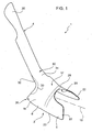
- the device 1 is symmetrical in relation to a vertical median plane and comprises a base support 3 and an upper handle 4, which is fixed and faces upwards in relation to the support 3.
- the handle 4 and the support 3 are preferably made in one-piece by injection moulding, in particular to obtain a device 1 with a constant thickness.
- the support 3 comprises a front end portion 5 and a saddle-shaped portion 6, which defines a downwards-facing cavity 14.
- the cavity 14 extends in a longitudinal direction 15 from the portion 5 up to a rear opening 16, beneath the handle 4.
- the portion 6 has a convex upper outside surface 17, upon which, in use, at least a portion of the hosiery to be donned is gathered.
- the portion 6 comprises two side walls 18, which extend in a cantilevered fashion downwards in relation to an upper inside surface 19 of the cavity 14 and have respective curved lower edges 20 with a downwardly-facing convexity.
- the device 1 has a center of gravity in a position such as to be balanced when standing on the floor resting on the edges 20.
- the height of the walls 18, i.e. the vertical distance between the surface 19 and the edges 20, increases from the portion 5 towards the opening 16.
- the portion 5 is appropriately shaped and, thanks to the type and thickness of the material that is used, it is elastically deformable, so that the support 3 can be inserted into the sock or stocking to be donned.
- the portion 5 comprises two flanges 22, which extend towards the front in a cantilevered fashion from the walls 18 of the portion 6, face one another, and are concave towards the inside of said cavity 14.
- the edges of the flanges 22 have a rounded upper and lower corner, to facilitate the application of the hosiery, and between them superiorly define a recess 25, the profile of which in a plan view is essentially U-shaped.
- the walls 18 have two notches 26, which are essentially obtained in correspondence with the opening 16 and are used to engage internally a top border of the hosiery.
- the portion 6 has a projection 28, which is arranged on the surface 17 in a position adjacent to the recess 25, it extends in an arch-like way, and is transversal in relation to the direction 15.
- the portion 6 is joined to the handle 4 by means of a fitting portion 30, which comprises a front area 31 and two side areas 32 or ribs, which define respective folds 33 in relation to the area 31 and to the walls 18.
- the folds 33 reinforce the portion 30 in case of anomalous stress or bending between the handle 4 and the support 3.
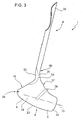
- the handle 4 consists of an elongated rectilinear portion that is essentially at a right angle to the direction 15. As shown in the side view in figure 3 and in the cross-section in figure 4 , the handle 4 is radiused via the area 31 to the upper profile of the portion 6, which is essentially rectilinear and forms an obtuse angle A with the handle 4.
- the angle A in particular, is between 135° and 145°.
- the handle 4 has an essentially semi-circular cross-section with the concavity facing towards the rear, so as to essentially fit against the user's leg.
- the upper end of the handle 4 is indicated by reference number 35 and defines a shoehorn, which can also be used to remove the hosiery after use.
- the hosiery to be donned is placed around the support 3, gradually inserting the portion 5 into the hosiery in the direction 15 and gathering the hosiery on the portion 6 beyond the projection 28, until the portion 5 enters the toe portion of said hosiery.
- the projection 28 prevents the sock or stocking from slipping towards the portion 5, while it is being gathered around the portion 6. Meanwhile, the top border of the sock or stocking is pushed into the notches 26. In this way, said border is held in a fixed position exactly in correspondence with the rear opening 16.
- the foot is placed through the opening 16 and into the cavity 14, while pulling the handle 4 of the device 1 parallel to the direction 15 towards the leg.
- the foot is gradually inserted into the cavity 14 in the direction 15, as the surface 19 is made to slide over the upper surface of the foot, until the tip of the foot pushes against the toe portion of the sock or stocking. This push causes the toe portion of the hosiery to slide off the portion 5 and settle against the tip of the foot.
- the retaining force exerted by the notches 26 and, especially, by the projection 28, prevents the hosiery from coming off the support 3 all at once. In other words, as the tip of the foot pushes against the toe portion of the hosiery, the projection 28 allows the hosiery to slide off gradually.
- the shape of the surface 19 and of the connection defined by the portion 30 essentially matches the shape of the upper surface and instep of the foot.
- the handle 4 is tilted forwards manually leaving the surface 19 in contact with the instep of the foot and making the upper surface of the foot enter the recess 25, until the calf is aligned with the opening 16.
- the notches 26 and the walls 18 accompany the portion of the hosiery that closes the lower part of the cavity 14 over the heel.
- the device 1 can even be used by people who have difficulty bending their backs or legs, enabling them to put their own hosiery on in a simple manner, regardless of the material out of which said hosiery is made.
- the shoehorn function performed by the end of the handle makes the device 1 even more useful.
- the device 1 is a one-piece construction makes it extremely simple to use and cheap to produce.
- the device 1 is particularly advantageous due to the total absence of any mechanisms, sharp edges, appendices or other accessories that could threaten the safety of the user and/or make the donning of hosiery more complicated.
- the handle could be a separate part attached to the support 3, and possibly detachable from the support 3.
- the parts of the device 1 could have different proportions to those illustrated herein.
Landscapes
- Holders For Apparel And Elements Relating To Apparel (AREA)
- Socks And Pantyhose (AREA)
Claims (12)
- Anziehvorrichtung (1) für Strumpfwaren, insbesondere für Kompressionsstrümpfe, umfassend:- einen Träger (3), umfassend:a) einen Vorderendabschnitt (5), welcher in den anzuziehenden Strumpf eingesetzt werden kann undb) einen sattelförmigen Abschnitt (6), welcher Rückhaltemittel (26, 28) umfasst, um zumindest einen Teil eines Stoffes des Strumpfes zu halten, welcher eine konvexe obere Außenfläche (17) aufweist, und welcher eine Kavität (14) definiert, in welche bei Verwendung, um den Strumpf anzuziehen, ein Fuß platziert wird, wobei die Kavität (14) nach unten gerichtet ist, um zu ermöglichen, dass der Träger (3) bei Verwendung über die obere Fläche und den Spann des Fußes gleitet;- ein Griffstück (4), welches in Bezug auf den Träger (3) nach oben gerichtet ist;- einen verbindenden Abschnitt (30), um das Griffstück (4) an den Träger (3) an dem dem Vorderendabschnitt (5) entgegengesetzten Ende in einer relativ festen Position zu binden;dadurch gekennzeichnet, dass:- die Rückhaltemittel (26, 28) dazu ausgebildet sind, einen gerafften Teil des Strumpfes auf der konvexen oberen Außenfläche (17) zu halten;- der Vorderendabschnitt (5) zwei Flansche (22) umfasst, welche sich freitragend von dem sattelförmigen Abschnitt (6) gegen die Front erstrecken, sich gegenüberstehen und zwischen ihren oberen Kanten eine Aussparung (25) definieren, deren Profil in einer Schnittansicht U-förmig ist; wobei bei Verwendung die Aussparung (25) von der oberen Fläche des Fußes eingenommen wird, wenn das Griffteil (4), mit dem sattelförmigen Abschnitt (6) im Kontakt mit dem Spann des Fußes, nach vorne gekippt wird.
- Vorrichtung gemäß Anspruch 1, dadurch gekennzeichnet, dass der sattelförmige Abschnitt (6) zwei Seitenwände (18) umfasst, welche sich freitragend nach unten erstrecken und bei Verwendung einen Teil des Strumpfes über die Ferse des Fußes geleiten, wenn das Griffteil (4), mit dem sattelförmigen Abschnitt (6) im Kontakt mit dem Spann des Fußes, nach vorne gekippt wird; wobei die Seitenwände (18) gekrümmte untere Kanten (20) mit einer nach unten gerichteten Konvexität aufweisen.
- Vorrichtung gemäß Anspruch 2, dadurch gekennzeichnet, dass sie ein Schwerezentrum an einem Ort derart aufweist, dass sie auf den gekrümmten unteren Kanten (20) auf dem Boden stehend ausbalanciert ist.
- Vorrichtung gemäß einem der vorhergehenden Ansprüche, dadurch gekennzeichnet, dass die Flansche (22) in Richtung des Inneren der Kavität (14) konkav sind, wobei die Kanten der Flansche (22) entsprechend eine abgerundete obere und untere Ecke aufweisen.
- Vorrichtung gemäß einem der vorhergehenden Ansprüche, dadurch gekennzeichnet, dass die Rückhaltemittel zumindest eine Kerbe (26) auf einer Kante des sattelförmigen Abschnitts (6) umfassen, wobei die Kerbe (26) in Übereinstimmung mit einer rückwärtigen Öffnung (16) der Kavität (14) ausgebildet ist.
- Vorrichtung gemäß einem der vorhergehenden Ansprüche, dadurch gekennzeichnet, dass der verbindende Abschnitt (30), das Griffteil (4) und der Träger (3) einstückig ausgebildet sind.
- Vorrichtung gemäß Anspruch 6, dadurch gekennzeichnet, dass der verbindende Abschnitt (30) ein Einbauabschnitt ist, welcher zwei verstärkende Seitenfalze (33) aufweist.
- Vorrichtung gemäß einem der vorhergehenden Ansprüche, dadurch gekennzeichnet, dass die Rückhaltemittel zumindest einen Vorsprung (28) umfassen, welcher an einer Stelle in der Nähe der Aussparung (25) angeordnet ist und welcher sich bogenförmig auf der oberen Außenfläche (17) erstreckt.
- Vorrichtung gemäß einem der vorhergehenden Ansprüche, dadurch gekennzeichnet, dass zumindest der Vorderendabschnitt (5) elastisch deformierbar ist.
- Vorrichtung gemäß einem der vorhergehenden Ansprüche, dadurch gekennzeichnet, dass sie aus einem auf Nylon basiertem Plastikmaterial mit Zusatz von Glasfasern hergestellt ist.
- Vorrichtung gemäß einem der Ansprüche 1 bis 9, dadurch gekennzeichnet, dass sie aus einem aus Getreide (cereals) gewonnenem Material hergestellt ist.
- Vorrichtung gemäß einem der vorhergehenden Ansprüche, dadurch gekennzeichnet, dass das obere Profil des sattelförmigen Abschnitts (6) im Wesentlichen geradlinig ausgebildet ist und mit dem Griffteil (4) einen stumpfen Winkel (A) zwischen 135° und 145° bildet.
Applications Claiming Priority (2)
| Application Number | Priority Date | Filing Date | Title |
|---|---|---|---|
| IT000012A ITVB20060012A1 (it) | 2006-12-28 | 2006-12-28 | Inseritore ed estrattore di calze con calzascarpe in pezzo unico |
| PCT/IB2007/004106 WO2008081294A1 (en) | 2006-12-28 | 2007-12-27 | Hosiery donning device, in particular for compression hosiery |
Publications (2)
| Publication Number | Publication Date |
|---|---|
| EP2096966A1 EP2096966A1 (de) | 2009-09-09 |
| EP2096966B1 true EP2096966B1 (de) | 2010-04-21 |
Family
ID=39410074
Family Applications (1)
| Application Number | Title | Priority Date | Filing Date |
|---|---|---|---|
| EP07859189A Ceased EP2096966B1 (de) | 2006-12-28 | 2007-12-27 | Anziehvorrichtung für strumpfwaren, im besonderen für kompressionsstrümpfe |
Country Status (6)
| Country | Link |
|---|---|
| US (1) | US9161646B2 (de) |
| EP (1) | EP2096966B1 (de) |
| AT (1) | ATE464816T1 (de) |
| DE (1) | DE602007006054D1 (de) |
| IT (1) | ITVB20060012A1 (de) |
| WO (1) | WO2008081294A1 (de) |
Families Citing this family (9)
| Publication number | Priority date | Publication date | Assignee | Title |
|---|---|---|---|---|
| ITVB20060012A1 (it) * | 2006-12-28 | 2008-06-29 | Silvia Bertinotti | Inseritore ed estrattore di calze con calzascarpe in pezzo unico |
| ITMI20101365A1 (it) * | 2010-07-23 | 2012-01-24 | Fiore Casari | Dispositivo per consentire l'infilaggio di una calza su un piede. |
| US9144339B2 (en) * | 2011-05-28 | 2015-09-29 | Joseph M. Cannata | Device to dress socks on and off |
| JP5776030B2 (ja) * | 2012-12-05 | 2015-09-09 | 信幸 岡室 | 下衣の装着自助具 |
| US8919620B2 (en) * | 2013-03-12 | 2014-12-30 | Kevin Darrell Taylor | Long handled sock donning tool and method of use |
| GB2539632B (en) * | 2015-05-06 | 2020-09-23 | Rayne Damian | An apparatus for assisting with the application of a garment |
| CN104957949B (zh) * | 2015-07-31 | 2017-08-25 | 都奥实业有限公司 | 穿袜辅助装置 |
| USD855282S1 (en) * | 2016-10-26 | 2019-08-06 | Damian RAYNE | Sock horn |
| US12274387B2 (en) | 2023-07-20 | 2025-04-15 | Barzetti Welding LLC | Device for getting socks on |
Family Cites Families (13)
| Publication number | Priority date | Publication date | Assignee | Title |
|---|---|---|---|---|
| US1374544A (en) * | 1921-01-24 | 1921-04-12 | Erik A Asplund | Overshoe-applicator |
| GB633930A (en) * | 1948-01-14 | 1949-12-30 | Fred Render | An appliance to aid the putting on of stockings and socks |
| US3692217A (en) * | 1970-12-18 | 1972-09-19 | Edward I Smith | Stocking appliance |
| GB2221604A (en) * | 1988-08-11 | 1990-02-14 | Koon Hing Trading Co Ltd | Shoe horn |
| US4943097A (en) | 1989-01-17 | 1990-07-24 | Yehuda Naim | Manually operable personal convenience implement |
| US5419283A (en) * | 1992-04-08 | 1995-05-30 | Ciuffo Gatto S.R.L. | Animal chew toy of starch material and degradable ethylene copolymer |
| FR2712162A1 (fr) | 1993-11-12 | 1995-05-19 | Darbonville Pierre Justin Augu | Instrument servant à l'enfilage de chaussettes, socquettes, bas et articles d'habillement similaire. |
| US6241134B1 (en) | 1998-09-22 | 2001-06-05 | David Dunkel | Apparatus and method for the removal of gloves |
| US6056171A (en) * | 1999-04-29 | 2000-05-02 | Santamaria; Eugene | Sock donning aid |
| FR2814930B1 (fr) * | 2000-10-05 | 2003-02-07 | Philippe Hermann | Dispositif a etrier pour enfiler un vetement |
| US6942129B2 (en) * | 2001-04-02 | 2005-09-13 | Michael P. Ferraioli | Footwear donning device |
| US20060025712A1 (en) * | 2004-07-27 | 2006-02-02 | Kammerer Donald J | Donning facilitator for dorsal wrap-around ankle-foot orthosis |
| ITVB20060012A1 (it) * | 2006-12-28 | 2008-06-29 | Silvia Bertinotti | Inseritore ed estrattore di calze con calzascarpe in pezzo unico |
-
2006
- 2006-12-28 IT IT000012A patent/ITVB20060012A1/it unknown
-
2007
- 2007-12-27 US US12/521,559 patent/US9161646B2/en not_active Expired - Fee Related
- 2007-12-27 WO PCT/IB2007/004106 patent/WO2008081294A1/en not_active Ceased
- 2007-12-27 AT AT07859189T patent/ATE464816T1/de not_active IP Right Cessation
- 2007-12-27 DE DE602007006054T patent/DE602007006054D1/de active Active
- 2007-12-27 EP EP07859189A patent/EP2096966B1/de not_active Ceased
Also Published As
| Publication number | Publication date |
|---|---|
| US20110049201A1 (en) | 2011-03-03 |
| DE602007006054D1 (de) | 2010-06-02 |
| WO2008081294A1 (en) | 2008-07-10 |
| ITVB20060012A1 (it) | 2008-06-29 |
| EP2096966A1 (de) | 2009-09-09 |
| US9161646B2 (en) | 2015-10-20 |
| ATE464816T1 (de) | 2010-05-15 |
Similar Documents
| Publication | Publication Date | Title |
|---|---|---|
| EP2096966B1 (de) | Anziehvorrichtung für strumpfwaren, im besonderen für kompressionsstrümpfe | |
| GB2616224A (en) | Footwear counter for easier entry and removal | |
| US9498077B2 (en) | Footwear application assisting apparatus | |
| US5249720A (en) | Tool for facilitating application of elastic stockings | |
| GB2369551A (en) | Footwear with shoehorn | |
| US20150083761A1 (en) | Combination Shoe Horn and Sock Donning and Doffing Apparatus | |
| US4943097A (en) | Manually operable personal convenience implement | |
| KR101999344B1 (ko) | 바른발 기능성 양말 | |
| US7328460B1 (en) | Pant leg lower end reinforcing structure and shoe and pant leg system | |
| EP2099339B1 (de) | Stiefelknecht | |
| US8047216B2 (en) | Standing aid | |
| US9144339B2 (en) | Device to dress socks on and off | |
| US20120211532A1 (en) | Method and apparatus for a shoehorn | |
| CN204814542U (zh) | 一种分体伸缩式骨科护理床 | |
| US8109418B1 (en) | Apparatus to enable removal of closely fitting attire on legs and feet | |
| GB2338172A (en) | Sock fitting and removal appliance | |
| US20040104254A1 (en) | Device for facilitating donning a sock | |
| US9167929B1 (en) | Boot doffing assistance device | |
| RU2730860C1 (ru) | Самообслуживаемое приспособление для надевания бахил | |
| JP2001353172A (ja) | 内反尖足の矯正用装具 | |
| US9198530B1 (en) | Footwear donning and removal system | |
| SI26403A (sl) | Pripomoček za brezročno obuvanje | |
| CN221242461U (zh) | 穿袜辅助器 | |
| JP3201746U (ja) | 靴下装着補助具 | |
| JP3166883U (ja) | 靴べら付靴脱ぎ器 |
Legal Events
| Date | Code | Title | Description |
|---|---|---|---|
| PUAI | Public reference made under article 153(3) epc to a published international application that has entered the european phase |
Free format text: ORIGINAL CODE: 0009012 |
|
| 17P | Request for examination filed |
Effective date: 20090630 |
|
| AK | Designated contracting states |
Kind code of ref document: A1 Designated state(s): AT BE BG CH CY CZ DE DK EE ES FI FR GB GR HU IE IS IT LI LT LU LV MC MT NL PL PT RO SE SI SK TR |
|
| GRAP | Despatch of communication of intention to grant a patent |
Free format text: ORIGINAL CODE: EPIDOSNIGR1 |
|
| GRAS | Grant fee paid |
Free format text: ORIGINAL CODE: EPIDOSNIGR3 |
|
| GRAA | (expected) grant |
Free format text: ORIGINAL CODE: 0009210 |
|
| DAX | Request for extension of the european patent (deleted) | ||
| AK | Designated contracting states |
Kind code of ref document: B1 Designated state(s): AT BE BG CH CY CZ DE DK EE ES FI FR GB GR HU IE IS IT LI LT LU LV MC MT NL PL PT RO SE SI SK TR |
|
| REG | Reference to a national code |
Ref country code: GB Ref legal event code: FG4D |
|
| REG | Reference to a national code |
Ref country code: CH Ref legal event code: EP |
|
| REG | Reference to a national code |
Ref country code: IE Ref legal event code: FG4D |
|
| REF | Corresponds to: |
Ref document number: 602007006054 Country of ref document: DE Date of ref document: 20100602 Kind code of ref document: P |
|
| REG | Reference to a national code |
Ref country code: NL Ref legal event code: VDEP Effective date: 20100421 |
|
| LTIE | Lt: invalidation of european patent or patent extension |
Effective date: 20100421 |
|
| PG25 | Lapsed in a contracting state [announced via postgrant information from national office to epo] |
Ref country code: NL Free format text: LAPSE BECAUSE OF FAILURE TO SUBMIT A TRANSLATION OF THE DESCRIPTION OR TO PAY THE FEE WITHIN THE PRESCRIBED TIME-LIMIT Effective date: 20100421 Ref country code: SE Free format text: LAPSE BECAUSE OF FAILURE TO SUBMIT A TRANSLATION OF THE DESCRIPTION OR TO PAY THE FEE WITHIN THE PRESCRIBED TIME-LIMIT Effective date: 20100421 Ref country code: ES Free format text: LAPSE BECAUSE OF FAILURE TO SUBMIT A TRANSLATION OF THE DESCRIPTION OR TO PAY THE FEE WITHIN THE PRESCRIBED TIME-LIMIT Effective date: 20100801 Ref country code: LT Free format text: LAPSE BECAUSE OF FAILURE TO SUBMIT A TRANSLATION OF THE DESCRIPTION OR TO PAY THE FEE WITHIN THE PRESCRIBED TIME-LIMIT Effective date: 20100421 |
|
| PG25 | Lapsed in a contracting state [announced via postgrant information from national office to epo] |
Ref country code: FI Free format text: LAPSE BECAUSE OF FAILURE TO SUBMIT A TRANSLATION OF THE DESCRIPTION OR TO PAY THE FEE WITHIN THE PRESCRIBED TIME-LIMIT Effective date: 20100421 Ref country code: AT Free format text: LAPSE BECAUSE OF FAILURE TO SUBMIT A TRANSLATION OF THE DESCRIPTION OR TO PAY THE FEE WITHIN THE PRESCRIBED TIME-LIMIT Effective date: 20100421 Ref country code: IS Free format text: LAPSE BECAUSE OF FAILURE TO SUBMIT A TRANSLATION OF THE DESCRIPTION OR TO PAY THE FEE WITHIN THE PRESCRIBED TIME-LIMIT Effective date: 20100821 Ref country code: LV Free format text: LAPSE BECAUSE OF FAILURE TO SUBMIT A TRANSLATION OF THE DESCRIPTION OR TO PAY THE FEE WITHIN THE PRESCRIBED TIME-LIMIT Effective date: 20100421 Ref country code: SI Free format text: LAPSE BECAUSE OF FAILURE TO SUBMIT A TRANSLATION OF THE DESCRIPTION OR TO PAY THE FEE WITHIN THE PRESCRIBED TIME-LIMIT Effective date: 20100421 |
|
| PG25 | Lapsed in a contracting state [announced via postgrant information from national office to epo] |
Ref country code: PL Free format text: LAPSE BECAUSE OF FAILURE TO SUBMIT A TRANSLATION OF THE DESCRIPTION OR TO PAY THE FEE WITHIN THE PRESCRIBED TIME-LIMIT Effective date: 20100421 Ref country code: CY Free format text: LAPSE BECAUSE OF FAILURE TO SUBMIT A TRANSLATION OF THE DESCRIPTION OR TO PAY THE FEE WITHIN THE PRESCRIBED TIME-LIMIT Effective date: 20100616 |
|
| PG25 | Lapsed in a contracting state [announced via postgrant information from national office to epo] |
Ref country code: PT Free format text: LAPSE BECAUSE OF FAILURE TO SUBMIT A TRANSLATION OF THE DESCRIPTION OR TO PAY THE FEE WITHIN THE PRESCRIBED TIME-LIMIT Effective date: 20100823 Ref country code: EE Free format text: LAPSE BECAUSE OF FAILURE TO SUBMIT A TRANSLATION OF THE DESCRIPTION OR TO PAY THE FEE WITHIN THE PRESCRIBED TIME-LIMIT Effective date: 20100421 Ref country code: DK Free format text: LAPSE BECAUSE OF FAILURE TO SUBMIT A TRANSLATION OF THE DESCRIPTION OR TO PAY THE FEE WITHIN THE PRESCRIBED TIME-LIMIT Effective date: 20100421 |
|
| PLBE | No opposition filed within time limit |
Free format text: ORIGINAL CODE: 0009261 |
|
| STAA | Information on the status of an ep patent application or granted ep patent |
Free format text: STATUS: NO OPPOSITION FILED WITHIN TIME LIMIT |
|
| PG25 | Lapsed in a contracting state [announced via postgrant information from national office to epo] |
Ref country code: CZ Free format text: LAPSE BECAUSE OF FAILURE TO SUBMIT A TRANSLATION OF THE DESCRIPTION OR TO PAY THE FEE WITHIN THE PRESCRIBED TIME-LIMIT Effective date: 20100421 Ref country code: BE Free format text: LAPSE BECAUSE OF FAILURE TO SUBMIT A TRANSLATION OF THE DESCRIPTION OR TO PAY THE FEE WITHIN THE PRESCRIBED TIME-LIMIT Effective date: 20100421 Ref country code: SK Free format text: LAPSE BECAUSE OF FAILURE TO SUBMIT A TRANSLATION OF THE DESCRIPTION OR TO PAY THE FEE WITHIN THE PRESCRIBED TIME-LIMIT Effective date: 20100421 Ref country code: RO Free format text: LAPSE BECAUSE OF FAILURE TO SUBMIT A TRANSLATION OF THE DESCRIPTION OR TO PAY THE FEE WITHIN THE PRESCRIBED TIME-LIMIT Effective date: 20100421 |
|
| 26N | No opposition filed |
Effective date: 20110124 |
|
| PG25 | Lapsed in a contracting state [announced via postgrant information from national office to epo] |
Ref country code: GR Free format text: LAPSE BECAUSE OF FAILURE TO SUBMIT A TRANSLATION OF THE DESCRIPTION OR TO PAY THE FEE WITHIN THE PRESCRIBED TIME-LIMIT Effective date: 20100722 |
|
| PG25 | Lapsed in a contracting state [announced via postgrant information from national office to epo] |
Ref country code: MC Free format text: LAPSE BECAUSE OF NON-PAYMENT OF DUE FEES Effective date: 20101231 |
|
| PG25 | Lapsed in a contracting state [announced via postgrant information from national office to epo] |
Ref country code: IE Free format text: LAPSE BECAUSE OF NON-PAYMENT OF DUE FEES Effective date: 20101227 |
|
| PG25 | Lapsed in a contracting state [announced via postgrant information from national office to epo] |
Ref country code: IT Free format text: LAPSE BECAUSE OF NON-PAYMENT OF DUE FEES Effective date: 20101227 Ref country code: MT Free format text: LAPSE BECAUSE OF FAILURE TO SUBMIT A TRANSLATION OF THE DESCRIPTION OR TO PAY THE FEE WITHIN THE PRESCRIBED TIME-LIMIT Effective date: 20100421 |
|
| REG | Reference to a national code |
Ref country code: CH Ref legal event code: PL |
|
| PG25 | Lapsed in a contracting state [announced via postgrant information from national office to epo] |
Ref country code: LU Free format text: LAPSE BECAUSE OF NON-PAYMENT OF DUE FEES Effective date: 20101227 Ref country code: HU Free format text: LAPSE BECAUSE OF FAILURE TO SUBMIT A TRANSLATION OF THE DESCRIPTION OR TO PAY THE FEE WITHIN THE PRESCRIBED TIME-LIMIT Effective date: 20101022 Ref country code: BG Free format text: LAPSE BECAUSE OF FAILURE TO SUBMIT A TRANSLATION OF THE DESCRIPTION OR TO PAY THE FEE WITHIN THE PRESCRIBED TIME-LIMIT Effective date: 20100421 |
|
| PG25 | Lapsed in a contracting state [announced via postgrant information from national office to epo] |
Ref country code: CH Free format text: LAPSE BECAUSE OF NON-PAYMENT OF DUE FEES Effective date: 20111231 Ref country code: LI Free format text: LAPSE BECAUSE OF NON-PAYMENT OF DUE FEES Effective date: 20111231 Ref country code: TR Free format text: LAPSE BECAUSE OF FAILURE TO SUBMIT A TRANSLATION OF THE DESCRIPTION OR TO PAY THE FEE WITHIN THE PRESCRIBED TIME-LIMIT Effective date: 20100421 |
|
| PG25 | Lapsed in a contracting state [announced via postgrant information from national office to epo] |
Ref country code: BG Free format text: LAPSE BECAUSE OF FAILURE TO SUBMIT A TRANSLATION OF THE DESCRIPTION OR TO PAY THE FEE WITHIN THE PRESCRIBED TIME-LIMIT Effective date: 20100721 |
|
| REG | Reference to a national code |
Ref country code: FR Ref legal event code: PLFP Year of fee payment: 9 |
|
| REG | Reference to a national code |
Ref country code: FR Ref legal event code: PLFP Year of fee payment: 10 |
|
| REG | Reference to a national code |
Ref country code: FR Ref legal event code: PLFP Year of fee payment: 11 |
|
| PGFP | Annual fee paid to national office [announced via postgrant information from national office to epo] |
Ref country code: DE Payment date: 20181218 Year of fee payment: 12 |
|
| PGFP | Annual fee paid to national office [announced via postgrant information from national office to epo] |
Ref country code: GB Payment date: 20181214 Year of fee payment: 12 Ref country code: FR Payment date: 20181214 Year of fee payment: 12 Ref country code: IT Payment date: 20181217 Year of fee payment: 12 |
|
| REG | Reference to a national code |
Ref country code: DE Ref legal event code: R119 Ref document number: 602007006054 Country of ref document: DE |
|
| GBPC | Gb: european patent ceased through non-payment of renewal fee |
Effective date: 20191227 |
|
| PG25 | Lapsed in a contracting state [announced via postgrant information from national office to epo] |
Ref country code: DE Free format text: LAPSE BECAUSE OF NON-PAYMENT OF DUE FEES Effective date: 20200701 Ref country code: IT Free format text: LAPSE BECAUSE OF NON-PAYMENT OF DUE FEES Effective date: 20191227 Ref country code: GB Free format text: LAPSE BECAUSE OF NON-PAYMENT OF DUE FEES Effective date: 20191227 Ref country code: FR Free format text: LAPSE BECAUSE OF NON-PAYMENT OF DUE FEES Effective date: 20191231 |