EP2096466B1 - A detector for detecting a current carrying conductor and a method of validating operation of the detector - Google Patents
A detector for detecting a current carrying conductor and a method of validating operation of the detector Download PDFInfo
- Publication number
- EP2096466B1 EP2096466B1 EP09250563.5A EP09250563A EP2096466B1 EP 2096466 B1 EP2096466 B1 EP 2096466B1 EP 09250563 A EP09250563 A EP 09250563A EP 2096466 B1 EP2096466 B1 EP 2096466B1
- Authority
- EP
- European Patent Office
- Prior art keywords
- detector
- test
- antennas
- antenna
- results
- Prior art date
- Legal status (The legal status is an assumption and is not a legal conclusion. Google has not performed a legal analysis and makes no representation as to the accuracy of the status listed.)
- Active
Links
Images

Classifications
-
- G—PHYSICS
- G01—MEASURING; TESTING
- G01V—GEOPHYSICS; GRAVITATIONAL MEASUREMENTS; DETECTING MASSES OR OBJECTS; TAGS
- G01V3/00—Electric or magnetic prospecting or detecting; Measuring magnetic field characteristics of the earth, e.g. declination, deviation
- G01V3/08—Electric or magnetic prospecting or detecting; Measuring magnetic field characteristics of the earth, e.g. declination, deviation operating with magnetic or electric fields produced or modified by objects or geological structures or by detecting devices
- G01V3/081—Electric or magnetic prospecting or detecting; Measuring magnetic field characteristics of the earth, e.g. declination, deviation operating with magnetic or electric fields produced or modified by objects or geological structures or by detecting devices the magnetic field is produced by the objects or geological structures
-
- G—PHYSICS
- G01—MEASURING; TESTING
- G01R—MEASURING ELECTRIC VARIABLES; MEASURING MAGNETIC VARIABLES
- G01R29/00—Arrangements for measuring or indicating electric quantities not covered by groups G01R19/00 - G01R27/00
- G01R29/08—Measuring electromagnetic field characteristics
- G01R29/0807—Measuring electromagnetic field characteristics characterised by the application
- G01R29/0814—Field measurements related to measuring influence on or from apparatus, components or humans, e.g. in ESD, EMI, EMC, EMP testing, measuring radiation leakage; detecting presence of micro- or radiowave emitters; dosimetry; testing shielding; measurements related to lightning
- G01R29/085—Field measurements related to measuring influence on or from apparatus, components or humans, e.g. in ESD, EMI, EMC, EMP testing, measuring radiation leakage; detecting presence of micro- or radiowave emitters; dosimetry; testing shielding; measurements related to lightning for detecting presence or location of electric lines or cables
-
- G—PHYSICS
- G01—MEASURING; TESTING
- G01V—GEOPHYSICS; GRAVITATIONAL MEASUREMENTS; DETECTING MASSES OR OBJECTS; TAGS
- G01V13/00—Manufacturing, calibrating, cleaning, or repairing instruments or devices covered by groups G01V1/00 – G01V11/00
-
- G—PHYSICS
- G01—MEASURING; TESTING
- G01V—GEOPHYSICS; GRAVITATIONAL MEASUREMENTS; DETECTING MASSES OR OBJECTS; TAGS
- G01V3/00—Electric or magnetic prospecting or detecting; Measuring magnetic field characteristics of the earth, e.g. declination, deviation
- G01V3/02—Electric or magnetic prospecting or detecting; Measuring magnetic field characteristics of the earth, e.g. declination, deviation operating with propagation of electric current
- G01V3/06—Electric or magnetic prospecting or detecting; Measuring magnetic field characteristics of the earth, e.g. declination, deviation operating with propagation of electric current using ac
-
- G—PHYSICS
- G01—MEASURING; TESTING
- G01V—GEOPHYSICS; GRAVITATIONAL MEASUREMENTS; DETECTING MASSES OR OBJECTS; TAGS
- G01V3/00—Electric or magnetic prospecting or detecting; Measuring magnetic field characteristics of the earth, e.g. declination, deviation
- G01V3/08—Electric or magnetic prospecting or detecting; Measuring magnetic field characteristics of the earth, e.g. declination, deviation operating with magnetic or electric fields produced or modified by objects or geological structures or by detecting devices
- G01V3/10—Electric or magnetic prospecting or detecting; Measuring magnetic field characteristics of the earth, e.g. declination, deviation operating with magnetic or electric fields produced or modified by objects or geological structures or by detecting devices using induction coils
- G01V3/104—Electric or magnetic prospecting or detecting; Measuring magnetic field characteristics of the earth, e.g. declination, deviation operating with magnetic or electric fields produced or modified by objects or geological structures or by detecting devices using induction coils using several coupled or uncoupled coils
Definitions
- the present invention relates to a detector for detecting a current carrying conductor and a method of validating operation of the detector.
- the depth of the utility can be calculated to determine a safe excavation depth. It is important that the depth information provided to the operator is accurate so as to avoid damage to the buried utility or injury to person when excavating the area.
- US-A-7336078 describes a portable locator for finding and mapping buried objects such as utilities.
- An articulatable antenna node configuration and the use of Doppler radar and GPS navigation are also disclosed.
- US-A-5541516 describes a system for use in determining the location and orientation of concealed underground objects and, more particularly, to a locator system having an improved interface with an operator.
- a swivel joint couples an upper housing portion and a lower housing portion.
- US-A-5043666 describes electromagnetic field sensing apparatus used for locating and determining the distance to buried conductive conduits including at least two receptor means, each adapted to receive a signal from the conduit and produce an output voltage proportional to the signal received, and also including a calibrating coil, with known relative coupling to the receptor means, and capable of inducing calibrating signals therein.
- EP 0 735 377 A2 describes a two-channel magnetic metal detector, wherein the inductance of the coils is tested by applying a square wave test signal to the first coil and determining whether the resulting output signal from the second coil has a magnitude falling within a range of magnitudes defined by two threshold values stored in a memory.
- a detector for detecting a buried conductor according to claim 1.
- the predetermined limits for each antenna may be the calibration data ⁇ 0.01%.
- the processor may be configured to disable the detector if one of the test currents is outside the predetermined limits of the calibration data.
- the plurality of antennas may comprise two or three parallel antennas which in use are oriented horizontally and spaced vertically.
- the processor may be configured to store results of the test in the memory.
- the detector may further comprise a user interface for conveying the results of the test to a user and a communications module for transmitting results of the test to another device.
- the system may further comprise a server connected to said network, wherein the server is configured to receive test results from the microprocessor-controlled device.
- the server may be configured to generate a calibration certificate if the test results indicate that said detector is operating within predetermined limits, the calibration certificate being downloadable from the server to the microprocessor-controlled device.
- the network may be the Internet.
- the predetermined limits for each antenna may be the calibration data ⁇ 0.01%.
- the processor may disable the detector if one of the test currents is outside the predetermined limits of the calibration data.
- the plurality of antennas may comprise two or three parallel antennas which in use are oriented horizontally and spaced vertically.
- the processor may store results of the test in the memory and the test may be conveyed to a user via a user interface.
- the method may further comprise: providing the detector with a communications module; providing a microprocessor-controlled device having a communications module for communicating with the communications module of the detector; and transmitting the results of the test from the detector to the microprocessor-controlled device via the communications modules.
- the method may further comprise: providing the microprocessor-controlled device with a communications module for accessing a network; and transmitting results of the test from the microprocessor-controlled device to said network.
- the method may further comprise: providing a server connected to said network; and transmitting results of the test from the microprocessor-controlled device to the server over said network.
- the method may further comprise: generating a calibration certificate at the server if the test results indicate that the detector is operating within predetermined limits and downloading the calibration certificate from the server to the microprocessor-controlled device.
- the network may be the Internet.
- the detector described above may further comprise a housing in which the other components of the detector are housed, wherein the detector is portable.
- a system for detecting a buried conductor comprising: a transmitter for generating an alternating current test signal in said conductor; and a detector as defined in claims 1 to 8 for detecting the signal generated in said buried conductor by the transmitter.
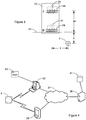
- Figure 1 is a schematic representation of a system 1 for detecting a buried conductor according to an embodiment of the invention, comprising a portable transmitter 3 and a portable receiver/detector 5.
- the transmitter 3 is placed in proximity to a buried conductor 7 to produce an alternating current test signal in the buried conductor 7.
- An aerial in the transmitter 3 is fed with an AC voltage to produce an electromagnetic field 9 which links with the buried conductor 7, thereby inducing the alternating current test signal in the buried conductor 7.
- the alternating current test signal is radiated as an electromagnetic field 11 by the buried conductor 7 and this electromagnetic field can be detected by the receiver 5.
- the transmitter may provide a test signal in the conductor by direct connection to the conductor or by clamping around the conductor, as is known in the art.
- FIG 2 is a block diagram of the receiver 5 of the system 1 of Figure 1 .
- An electromagnetic field 11 radiated by the buried conductor 7 is detected by a plurality of antennas in an antenna module 13. Each antenna outputs a field strength signal representative of the electromagnetic field 11 at the antenna.
- the outputs from the antenna module 13 are fed into a signal processor module 15 for isolating signals of a desired frequency band or bands and processing these signals to derive their characteristics using known techniques.
- the signal processor module 15 may comprise a pre-amplification stage for amplifying the field strength signals output from the antennas if the detected signal is weak.
- the signal processor module 15 may further comprise an analogue to digital converter for converting the field strength signals into digital signals and a digital signal processor for processing the digitised signals.
- the receiver comprises a communications module 17 to provide a communication/data link between the receiver 5 and a microprocessor-controlled device such as a personal computer (PC) or a personal digital assistant (PDA) (not shown).
- a microprocessor-controlled device such as a personal computer (PC) or a personal digital assistant (PDA) (not shown).
- the communication link may be implemented via a wired or wireless connection.
- the communications module 17 may provide a communication link with the transmitter 3.
- a user interface module 19 is provided to convey information to the operator of the receiver 5 and may comprise one or more of a display for displaying information to the operator of the device, input devices such as a keypad or a touch sensitive screen and an audible output device such as a speaker or beeper.
- the receiver 5 further comprises a memory module 21 and a power supply unit (PSU) 23 comprising power management circuitry and a power source such as batteries.
- PSU power supply unit
- FIG. 3 shows an antenna module 13 of a detector 5 comprising two horizontal vertically spaced antennas B, T.
- the detector 5 is held vertical on ground 27 in which a current carrying conductor 7 is buried, with the bottom antenna B close to the surface of the ground 27.
- the axes of the antennas are parallel and the separation between the bottom antenna B and the top antenna T is 2s.
- the conductor 7 is buried at a depth d below the surface of the ground 27 (and below the bottom antenna B) and the horizontal displacement between the antennas B and T and the conductor 7 is x.
- the components of the portable detector 5 are housed in a housing (not shown).
- the magnetic flux density or magnetic field at the bottom antenna B is B B and the magnetic flux density at the top antenna T is B T .
- each antenna B, T is provided with a winding 29 (shown in dotted lines) which is wound around the ferrite of the antenna and connected to a precision current source 31 (shown in dotted lines) to provide an integrated built-in test capability.
- a precision current source 31 shown in dotted lines
- the predefined test current is generated by the precision current sources 31 and passed through the windings 29 to produce electromagnetic fields at the antennas B, T which induces test currents in the respective antennas B, T.
- the test currents output from the antennas B, T are compared to the factory calibration data stored in the memory 21 for each antenna B, T to verify that the currents are within predetermined limits of the factory calibration data. If the currents output from both of the antennas B, T are within the predetermined limits then the calibration test is deemed to be a pass.
- the predetermined limit for each antenna is that the test current is within the factory calibration data ⁇ 0.01% (i.e., 1 part in 10,000).
- the calibration test is deemed to be a fail.
- the results of the integrated built-in test are conveyed to the user by means of the user interface 19 and stored in the memory 21. If the detector 5 fails the integrated built-in test then a warning is displayed to indicate that the detector 5 is out of calibration. Alternatively or additionally the controller 25 may lock the detector 5 to prevent its use until the detector is recalibrated and the integrated built-in test is passed.
- Figure 4 shows a system for validating the operation of the detector of Figure 2 .
- the detector 5 communicates via its communications module 17 with a communications module of a PC 33, a PDA 35 or other microprocessor-controlled device (not shown).
- the detector 5 communicates wirelessly with the PC 33 and PDA 35 but in other embodiments the detector 5 may communicate via a wired connection.
- the PC 33 and PDA 35 are connected or connectable via a network 37, such as the Internet, to a server 39.
- the server 39 can access a storage device 41.
- the results of the calibration test together with an identifier of the detector 5, such as a serial number, can be uploaded from the memory 21 of the detector 5 to the PC 33 or PDA 35 and from there via the network 37 to a server 39 so that the results can be stored in the memory 41 associated with the server 39 to record the test results and whether the detector 5 passed or failed the calibration test on the date in question. If the calibration test was passed then the server 39 can generate a test pass certificate which can be downloaded to the PC 33 or PDA 35. A printer 43 connected to the PC 33 can print the calibration certificate to show that the detector 5 passed the calibration test on the date in question.
- the detector 5 shown in the Figures comprises two parallel horizontal antennas. It will be understood by a person skilled in the art that the detector may comprise three parallel horizontal antennas or more and that some or all of the antennas may comprise a winding wound around the ferrite of the antenna and connected to a precision current source to provide an integrated built-in test capability for some or all of the antennas.
- aspects of the present invention can be implemented in any convenient form, for example using dedicated hardware, or a mixture of dedicated hardware and software.
- the processing apparatuses can comprise any suitably programmed apparatuses such as a general purpose computer, personal digital assistant, mobile telephone (such as a WAP or 3G-compliant phone) and so on. Since the present invention can be implemented as software, each and every aspect of the present invention thus encompasses computer software implementable on a programmable device.
- the computer software can be provided to the programmable device using any conventional carrier medium.
- the carrier medium can comprise a transient carrier medium such as an electrical, optical, microwave, acoustic or radio frequency signal carrying the computer code.
- An example of such a transient medium is a TCP/IP signal carrying computer code over an IP network, such as the Internet.
- the carrier medium can also comprise a storage medium for storing processor readable code such as a floppy disk, hard disk, CD ROM, magnetic tape device or solid state memory device.
Landscapes
- Physics & Mathematics (AREA)
- Engineering & Computer Science (AREA)
- Life Sciences & Earth Sciences (AREA)
- Remote Sensing (AREA)
- General Physics & Mathematics (AREA)
- Geophysics (AREA)
- General Life Sciences & Earth Sciences (AREA)
- Geology (AREA)
- Environmental & Geological Engineering (AREA)
- Electromagnetism (AREA)
- Manufacturing & Machinery (AREA)
- Geophysics And Detection Of Objects (AREA)
- Near-Field Transmission Systems (AREA)
Applications Claiming Priority (1)
| Application Number | Priority Date | Filing Date | Title |
|---|---|---|---|
| GB0803873.9A GB2457954B (en) | 2008-02-29 | 2008-02-29 | A detector for detecting a current carrying conductor and a method of validating operations of the detector |
Publications (3)
| Publication Number | Publication Date |
|---|---|
| EP2096466A2 EP2096466A2 (en) | 2009-09-02 |
| EP2096466A3 EP2096466A3 (en) | 2011-03-02 |
| EP2096466B1 true EP2096466B1 (en) | 2019-12-11 |
Family
ID=39315814
Family Applications (1)
| Application Number | Title | Priority Date | Filing Date |
|---|---|---|---|
| EP09250563.5A Active EP2096466B1 (en) | 2008-02-29 | 2009-02-27 | A detector for detecting a current carrying conductor and a method of validating operation of the detector |
Country Status (6)
| Country | Link |
|---|---|
| US (1) | US8115489B2 (zh) |
| EP (1) | EP2096466B1 (zh) |
| CN (2) | CN201555556U (zh) |
| CA (1) | CA2656257C (zh) |
| ES (1) | ES2762429T3 (zh) |
| GB (1) | GB2457954B (zh) |
Families Citing this family (21)
| Publication number | Priority date | Publication date | Assignee | Title |
|---|---|---|---|---|
| GB2457954B (en) * | 2008-02-29 | 2012-04-04 | Radiodetection Ltd | A detector for detecting a current carrying conductor and a method of validating operations of the detector |
| US8729901B2 (en) | 2009-07-06 | 2014-05-20 | Merlin Technology, Inc. | Measurement device and associated method for use in frequency selection for inground transmission |
| NL2007986C2 (nl) * | 2011-12-16 | 2013-07-15 | Roos & Bijl B V | Werkwijze en systeem voor het bepalen van een in ten minste ã©ã©n ondergrondse buisleiding geã¯nduceerde stroomsterkte, werkwijze voor het reduceren van de gevolgen van de geã¯nduceerde stroom, computerprogramma en informatiedrager. |
| EP2645133A1 (en) | 2012-03-30 | 2013-10-02 | Leica Geosystems AG | Buried service detection |
| JP5980611B2 (ja) * | 2012-07-25 | 2016-08-31 | オリンパス株式会社 | 計測内視鏡装置およびプログラム |
| US20140225618A1 (en) * | 2013-02-08 | 2014-08-14 | Radiodetection Ltd. | Remote control switching device to control separate detection of a plurality of buried conductors |
| US20140225617A1 (en) * | 2013-02-08 | 2014-08-14 | Radiodetection Ltd. | Remote control switching device to control separate detection of a plurality buried conductors |
| US20150097569A1 (en) * | 2013-10-04 | 2015-04-09 | Radiodetection Limited | Validating Operation of an Electronic Marker Locator |
| GB2518888B (en) * | 2013-10-04 | 2020-07-29 | Radiodetection Ltd | Validating Operation of an Electronic Marker Locator |
| EP3052972B1 (en) * | 2013-10-04 | 2021-04-28 | Radiodetection Limited | Validating operation of an electronic marker locator |
| GB2523326B (en) * | 2014-02-19 | 2017-11-29 | Vivax-Metrotech Ltd | Detection apparatus with self-test function |
| CN104156112B (zh) * | 2014-08-11 | 2017-08-29 | 北京航空航天大学 | 地下管道数据终端 |
| US9739140B2 (en) | 2014-09-05 | 2017-08-22 | Merlin Technology, Inc. | Communication protocol in directional drilling system, apparatus and method utilizing multi-bit data symbol transmission |
| US10209385B2 (en) | 2014-10-03 | 2019-02-19 | Cable Detection Limited | Buried service detection |
| EP3002614B1 (en) | 2014-10-03 | 2021-02-24 | Cable Detection Limited | Buried service detection |
| US9857494B2 (en) | 2015-12-01 | 2018-01-02 | Mclaughlin Group, Inc. | System and method for locating an underground utility |
| US10378338B2 (en) | 2017-06-28 | 2019-08-13 | Merlin Technology, Inc. | Advanced passive interference management in directional drilling system, apparatus and methods |
| CN109296947A (zh) * | 2017-07-25 | 2019-02-01 | 中国石油天然气股份有限公司 | 管道水下穿越段外防腐层破损点的定位方法及装置 |
| CN109296946B (zh) * | 2017-07-25 | 2020-08-11 | 中国石油天然气股份有限公司 | 管道水下穿越段外防腐层绝缘电阻率的确定方法及装置 |
| CN110989012B (zh) * | 2019-12-18 | 2022-04-05 | 浙江省特种设备科学研究院 | 地下管道设深度的精确电磁测量方法及管线仪装置 |
| RU2743888C1 (ru) * | 2020-08-11 | 2021-03-01 | Федеральное государственное бюджетное образовательное учреждение высшего образования "Поволжский государственный университет телекоммуникаций и информатики" | Способ контроля глубины прокладки оптического кабеля |
Citations (2)
| Publication number | Priority date | Publication date | Assignee | Title |
|---|---|---|---|---|
| EP0735377A2 (en) * | 1995-03-31 | 1996-10-02 | New Holland Belgium N.V. | Metal detector coil inductance testing |
| US20030158708A1 (en) * | 2002-02-15 | 2003-08-21 | Radiodetection Limited | Method and system for remotely servicing a detection device |
Family Cites Families (22)
| Publication number | Priority date | Publication date | Assignee | Title |
|---|---|---|---|---|
| FR2349841A1 (fr) * | 1976-04-26 | 1977-11-25 | Commissariat Energie Atomique | Procede de detection de canalisations enterrees et de mesure de la profondeur desdites canalisations et dispositif en faisant application |
| GB2070783B (en) * | 1980-03-05 | 1984-07-04 | Howell M I | Measuring current in a conductor |
| US4387340A (en) * | 1980-07-31 | 1983-06-07 | Metrotech, Inc. | Apparatus for determining the distance to a concealed conductive object which is radiating an alternating current signal |
| US5043666A (en) * | 1990-04-16 | 1991-08-27 | Metrotech Corporation | Self-calibrating electromagnetic field sensor for locating buried conduits |
| US5231355A (en) * | 1990-06-18 | 1993-07-27 | The Charles Machine Works, Inc. | Locator transmitter having an automatically tuned antenna |
| US7079591B2 (en) * | 2001-08-01 | 2006-07-18 | Radiodetection Limited | Method and system for recovering information from a magnetic field signal usable for locating an underground object |
| US7091872B1 (en) * | 2002-07-01 | 2006-08-15 | Metrotech Corporation | Controlled power source for underground line location |
| US7336078B1 (en) * | 2003-10-04 | 2008-02-26 | Seektech, Inc. | Multi-sensor mapping omnidirectional sonde and line locators |
| DE202004006336U1 (de) * | 2004-04-19 | 2004-07-01 | Vallon Gmbh | Handmetalldetektor |
| JP2006275959A (ja) * | 2005-03-30 | 2006-10-12 | Kyocera Mita Corp | 磁気センサ補正装置 |
| GB2427474B8 (en) * | 2005-06-20 | 2009-04-22 | Radiodetection Ltd | A method of and apparatus for determining if a buried current carrying conductor is buried above a predetermined minimum depth |
| GB2427475B (en) * | 2005-06-20 | 2008-07-09 | Radiodetection Ltd | A detector for detecting a buried current carrying conductor |
| GB2427476B (en) * | 2005-06-20 | 2008-06-25 | Radiodetection Ltd | A detector for detecting a buried current carrying conductor |
| GB2427473B (en) * | 2005-06-20 | 2008-07-23 | Radiodetection Ltd | A method of and apparatus for detecting a current carrying conductor |
| US7557559B1 (en) * | 2006-06-19 | 2009-07-07 | Seektech, Inc. | Compact line illuminator for locating buried pipes and cables |
| GB2457956B (en) * | 2008-02-29 | 2012-03-28 | Radiodetection Ltd | System for and method of detecting a buried conductor |
| GB2457953B (en) * | 2008-02-29 | 2012-02-08 | Radiodetection Ltd | Transmitter of a system for detecting a buried conductor |
| GB2457955B (en) * | 2008-02-29 | 2012-08-15 | Radiodetection Ltd | System for and method of detecting a buried conductor |
| GB2457954B (en) * | 2008-02-29 | 2012-04-04 | Radiodetection Ltd | A detector for detecting a current carrying conductor and a method of validating operations of the detector |
| GB2458120B (en) * | 2008-03-03 | 2012-07-25 | Radiodetection Ltd | A detector for calculating the depth of a buried conductor |
| GB2458119B (en) * | 2008-03-03 | 2010-12-29 | Radiodetection Ltd | A detector for calculating the distortion of an electromagnetic field produced by a buried current carrying conductor |
| GB2458121B (en) * | 2008-03-03 | 2012-01-25 | Radiodetection Ltd | A detector for calculating a depth of a buried conductor |
-
2008
- 2008-02-29 GB GB0803873.9A patent/GB2457954B/en active Active
-
2009
- 2009-02-27 EP EP09250563.5A patent/EP2096466B1/en active Active
- 2009-02-27 ES ES09250563T patent/ES2762429T3/es active Active
- 2009-02-27 CA CA2656257A patent/CA2656257C/en active Active
- 2009-03-02 US US12/395,838 patent/US8115489B2/en active Active
- 2009-03-02 CN CN2009200075708U patent/CN201555556U/zh not_active Expired - Lifetime
- 2009-03-02 CN CN2009101184196A patent/CN101526626B/zh not_active Expired - Fee Related
Patent Citations (2)
| Publication number | Priority date | Publication date | Assignee | Title |
|---|---|---|---|---|
| EP0735377A2 (en) * | 1995-03-31 | 1996-10-02 | New Holland Belgium N.V. | Metal detector coil inductance testing |
| US20030158708A1 (en) * | 2002-02-15 | 2003-08-21 | Radiodetection Limited | Method and system for remotely servicing a detection device |
Also Published As
| Publication number | Publication date |
|---|---|
| CA2656257A1 (en) | 2009-08-29 |
| US20100060285A1 (en) | 2010-03-11 |
| ES2762429T3 (es) | 2020-05-25 |
| CA2656257C (en) | 2016-06-14 |
| EP2096466A2 (en) | 2009-09-02 |
| GB2457954B (en) | 2012-04-04 |
| GB2457954A (en) | 2009-09-02 |
| US8115489B2 (en) | 2012-02-14 |
| CN101526626B (zh) | 2012-07-25 |
| GB0803873D0 (en) | 2008-04-09 |
| CN101526626A (zh) | 2009-09-09 |
| CN201555556U (zh) | 2010-08-18 |
| EP2096466A3 (en) | 2011-03-02 |
Similar Documents
| Publication | Publication Date | Title |
|---|---|---|
| EP2096466B1 (en) | A detector for detecting a current carrying conductor and a method of validating operation of the detector | |
| CA2656374C (en) | System for and method of detecting a buried conductor | |
| CA2656365C (en) | System for and method of detecting a buried conductor | |
| US11624851B1 (en) | Electronic marker devices and systems | |
| EP2098890B1 (en) | Detector for calculating the depth of a buried conductor | |
| EP2098888B1 (en) | A detector for calculating the distortion of an electromagnetic field produced by a buried current carrying conductor | |
| US20150281881A1 (en) | Locating Underground Markers | |
| WO2018112476A1 (en) | Systems and methods for electronically marking, locating and virtually displaying buried utilities | |
| WO2006088742A2 (en) | Digital locating system and device for underground object detection | |
| EP2098889A2 (en) | A detector for calculating a depth of a buried conductor | |
| CN108362372A (zh) | 低频噪声测试系统 | |
| CN212845973U (zh) | 改进型线缆探测仪 | |
| Sternberg et al. | Experimental studies and verification of the vertical array-differential target antenna coupling (DTAC) method for rapid sensing and imaging of subsurface targets | |
| CN111880230A (zh) | 改进型线缆探测仪 | |
| CN107063070A (zh) | 混凝土厚度无损检测仪 | |
| JP4059516B1 (ja) | 電磁波測定システム | |
| EP2589988B1 (en) | Locator for locating a current carrying conductor | |
| CN105849593A (zh) | 验证电子标记定位器的操作 | |
| EP2589989A2 (en) | Signal Generator |
Legal Events
| Date | Code | Title | Description |
|---|---|---|---|
| PUAI | Public reference made under article 153(3) epc to a published international application that has entered the european phase |
Free format text: ORIGINAL CODE: 0009012 |
|
| AK | Designated contracting states |
Kind code of ref document: A2 Designated state(s): AT BE BG CH CY CZ DE DK EE ES FI FR GB GR HR HU IE IS IT LI LT LU LV MC MK MT NL NO PL PT RO SE SI SK TR |
|
| AX | Request for extension of the european patent |
Extension state: AL BA RS |
|
| PUAL | Search report despatched |
Free format text: ORIGINAL CODE: 0009013 |
|
| AK | Designated contracting states |
Kind code of ref document: A3 Designated state(s): AT BE BG CH CY CZ DE DK EE ES FI FR GB GR HR HU IE IS IT LI LT LU LV MC MK MT NL NO PL PT RO SE SI SK TR |
|
| AX | Request for extension of the european patent |
Extension state: AL BA RS |
|
| 17P | Request for examination filed |
Effective date: 20110901 |
|
| AKX | Designation fees paid |
Designated state(s): DE ES FR IT NL |
|
| 17Q | First examination report despatched |
Effective date: 20130130 |
|
| GRAP | Despatch of communication of intention to grant a patent |
Free format text: ORIGINAL CODE: EPIDOSNIGR1 |
|
| GRAJ | Information related to disapproval of communication of intention to grant by the applicant or resumption of examination proceedings by the epo deleted |
Free format text: ORIGINAL CODE: EPIDOSDIGR1 |
|
| INTG | Intention to grant announced |
Effective date: 20190301 |
|
| GRAP | Despatch of communication of intention to grant a patent |
Free format text: ORIGINAL CODE: EPIDOSNIGR1 |
|
| GRAJ | Information related to disapproval of communication of intention to grant by the applicant or resumption of examination proceedings by the epo deleted |
Free format text: ORIGINAL CODE: EPIDOSDIGR1 |
|
| INTG | Intention to grant announced |
Effective date: 20190329 |
|
| GRAP | Despatch of communication of intention to grant a patent |
Free format text: ORIGINAL CODE: EPIDOSNIGR1 |
|
| GRAJ | Information related to disapproval of communication of intention to grant by the applicant or resumption of examination proceedings by the epo deleted |
Free format text: ORIGINAL CODE: EPIDOSDIGR1 |
|
| GRAP | Despatch of communication of intention to grant a patent |
Free format text: ORIGINAL CODE: EPIDOSNIGR1 |
|
| INTG | Intention to grant announced |
Effective date: 20190426 |
|
| INTG | Intention to grant announced |
Effective date: 20190509 |
|
| GRAJ | Information related to disapproval of communication of intention to grant by the applicant or resumption of examination proceedings by the epo deleted |
Free format text: ORIGINAL CODE: EPIDOSDIGR1 |
|
| GRAP | Despatch of communication of intention to grant a patent |
Free format text: ORIGINAL CODE: EPIDOSNIGR1 |
|
| INTG | Intention to grant announced |
Effective date: 20190624 |
|
| GRAS | Grant fee paid |
Free format text: ORIGINAL CODE: EPIDOSNIGR3 |
|
| GRAA | (expected) grant |
Free format text: ORIGINAL CODE: 0009210 |
|
| AK | Designated contracting states |
Kind code of ref document: B1 Designated state(s): DE ES FR IT NL |
|
| REG | Reference to a national code |
Ref country code: DE Ref legal event code: R096 Ref document number: 602009060672 Country of ref document: DE |
|
| REG | Reference to a national code |
Ref country code: NL Ref legal event code: FP |
|
| REG | Reference to a national code |
Ref country code: ES Ref legal event code: FG2A Ref document number: 2762429 Country of ref document: ES Kind code of ref document: T3 Effective date: 20200525 |
|
| REG | Reference to a national code |
Ref country code: DE Ref legal event code: R097 Ref document number: 602009060672 Country of ref document: DE |
|
| PLBE | No opposition filed within time limit |
Free format text: ORIGINAL CODE: 0009261 |
|
| STAA | Information on the status of an ep patent application or granted ep patent |
Free format text: STATUS: NO OPPOSITION FILED WITHIN TIME LIMIT |
|
| 26N | No opposition filed |
Effective date: 20200914 |
|
| PGFP | Annual fee paid to national office [announced via postgrant information from national office to epo] |
Ref country code: NL Payment date: 20230626 Year of fee payment: 15 Ref country code: FR Payment date: 20230626 Year of fee payment: 15 Ref country code: DE Payment date: 20230626 Year of fee payment: 15 |
|
| PGFP | Annual fee paid to national office [announced via postgrant information from national office to epo] |
Ref country code: IT Payment date: 20230720 Year of fee payment: 15 Ref country code: ES Payment date: 20230703 Year of fee payment: 15 |