EP2096462A1 - Object detecting apparatus - Google Patents
Object detecting apparatus Download PDFInfo
- Publication number
- EP2096462A1 EP2096462A1 EP08722269A EP08722269A EP2096462A1 EP 2096462 A1 EP2096462 A1 EP 2096462A1 EP 08722269 A EP08722269 A EP 08722269A EP 08722269 A EP08722269 A EP 08722269A EP 2096462 A1 EP2096462 A1 EP 2096462A1
- Authority
- EP
- European Patent Office
- Prior art keywords
- object detecting
- distance
- radar
- scan range
- scan
- Prior art date
- Legal status (The legal status is an assumption and is not a legal conclusion. Google has not performed a legal analysis and makes no representation as to the accuracy of the status listed.)
- Granted
Links
Images


Classifications
-
- G—PHYSICS
- G01—MEASURING; TESTING
- G01S—RADIO DIRECTION-FINDING; RADIO NAVIGATION; DETERMINING DISTANCE OR VELOCITY BY USE OF RADIO WAVES; LOCATING OR PRESENCE-DETECTING BY USE OF THE REFLECTION OR RERADIATION OF RADIO WAVES; ANALOGOUS ARRANGEMENTS USING OTHER WAVES
- G01S13/00—Systems using the reflection or reradiation of radio waves, e.g. radar systems; Analogous systems using reflection or reradiation of waves whose nature or wavelength is irrelevant or unspecified
- G01S13/88—Radar or analogous systems specially adapted for specific applications
- G01S13/93—Radar or analogous systems specially adapted for specific applications for anti-collision purposes
- G01S13/931—Radar or analogous systems specially adapted for specific applications for anti-collision purposes of land vehicles
-
- G—PHYSICS
- G01—MEASURING; TESTING
- G01S—RADIO DIRECTION-FINDING; RADIO NAVIGATION; DETERMINING DISTANCE OR VELOCITY BY USE OF RADIO WAVES; LOCATING OR PRESENCE-DETECTING BY USE OF THE REFLECTION OR RERADIATION OF RADIO WAVES; ANALOGOUS ARRANGEMENTS USING OTHER WAVES
- G01S13/00—Systems using the reflection or reradiation of radio waves, e.g. radar systems; Analogous systems using reflection or reradiation of waves whose nature or wavelength is irrelevant or unspecified
- G01S13/86—Combinations of radar systems with non-radar systems, e.g. sonar, direction finder
- G01S13/867—Combination of radar systems with cameras
-
- G—PHYSICS
- G01—MEASURING; TESTING
- G01S—RADIO DIRECTION-FINDING; RADIO NAVIGATION; DETERMINING DISTANCE OR VELOCITY BY USE OF RADIO WAVES; LOCATING OR PRESENCE-DETECTING BY USE OF THE REFLECTION OR RERADIATION OF RADIO WAVES; ANALOGOUS ARRANGEMENTS USING OTHER WAVES
- G01S17/00—Systems using the reflection or reradiation of electromagnetic waves other than radio waves, e.g. lidar systems
- G01S17/02—Systems using the reflection of electromagnetic waves other than radio waves
- G01S17/06—Systems determining position data of a target
- G01S17/42—Simultaneous measurement of distance and other co-ordinates
-
- G—PHYSICS
- G01—MEASURING; TESTING
- G01S—RADIO DIRECTION-FINDING; RADIO NAVIGATION; DETERMINING DISTANCE OR VELOCITY BY USE OF RADIO WAVES; LOCATING OR PRESENCE-DETECTING BY USE OF THE REFLECTION OR RERADIATION OF RADIO WAVES; ANALOGOUS ARRANGEMENTS USING OTHER WAVES
- G01S17/00—Systems using the reflection or reradiation of electromagnetic waves other than radio waves, e.g. lidar systems
- G01S17/88—Lidar systems specially adapted for specific applications
- G01S17/93—Lidar systems specially adapted for specific applications for anti-collision purposes
- G01S17/931—Lidar systems specially adapted for specific applications for anti-collision purposes of land vehicles
-
- G—PHYSICS
- G01—MEASURING; TESTING
- G01S—RADIO DIRECTION-FINDING; RADIO NAVIGATION; DETERMINING DISTANCE OR VELOCITY BY USE OF RADIO WAVES; LOCATING OR PRESENCE-DETECTING BY USE OF THE REFLECTION OR RERADIATION OF RADIO WAVES; ANALOGOUS ARRANGEMENTS USING OTHER WAVES
- G01S17/00—Systems using the reflection or reradiation of electromagnetic waves other than radio waves, e.g. lidar systems
- G01S17/86—Combinations of lidar systems with systems other than lidar, radar or sonar, e.g. with direction finders
-
- G—PHYSICS
- G01—MEASURING; TESTING
- G01S—RADIO DIRECTION-FINDING; RADIO NAVIGATION; DETERMINING DISTANCE OR VELOCITY BY USE OF RADIO WAVES; LOCATING OR PRESENCE-DETECTING BY USE OF THE REFLECTION OR RERADIATION OF RADIO WAVES; ANALOGOUS ARRANGEMENTS USING OTHER WAVES
- G01S13/00—Systems using the reflection or reradiation of radio waves, e.g. radar systems; Analogous systems using reflection or reradiation of waves whose nature or wavelength is irrelevant or unspecified
- G01S13/88—Radar or analogous systems specially adapted for specific applications
- G01S13/93—Radar or analogous systems specially adapted for specific applications for anti-collision purposes
- G01S13/931—Radar or analogous systems specially adapted for specific applications for anti-collision purposes of land vehicles
- G01S2013/9327—Sensor installation details
- G01S2013/93271—Sensor installation details in the front of the vehicles
Definitions
- the present invention relates to an object detecting apparatus.
- Priority is claimed on Japanese Patent Application No. 2007-078790, filed March 26, 2007 , the content of which is incorporated herein by reference.
- a technique is proposed in which a radar is mounted on a vehicle to detect objects in its surroundings (for example, refer to Patent Document 1).
- the present invention has an object of providing an object detecting apparatus that can detect an object in an arbitrary range, and obtain the distance between a plurality of objects.
- an object detecting apparatus includes: an object detecting device that causes electromagnetic waves to be reflected from an object and receives the reflected waves to detect the object while scanning a predetermined scan range; a rotating device that changes a direction of the object detecting device; an imaging device that captures images; a display device that displays an image captured by the imaging device; a setting device that sets the scan range of the object detecting device on the image displayed by the display device; and a control device that instructs the rotating device to rotate the object detecting device based on the set scan range, and instructs the object detecting device to scan the scan range.
- the object detecting apparatus since it has a rotating device that changes the direction of the object detecting device, then even in the case where an object detecting device with a narrow scan range is used, it is possible to detect objects in an arbitrary range. Furthermore, since it has a setting device that sets the scan range of the object detecting device on the image displayed, it is possible to set the scan range easily according to the intention of an operator. Moreover, since it has a control device that instructs the rotating device to rotate the object detecting device, and instructs the object detecting device to scan the scan range, then even if the scanning location of the object detecting device cannot be seen visually, it is possible to rotate the object detecting device with respect to the set scan range automatically, and scan.
- the object detecting apparatus further includes: a reflection point detecting device that detects a plurality of reflection points of the reflected waves from locations at a predetermined distance from the imaging device, based on a detection result of the object detecting device; and a reflection point-to-point distance computing device that calculates a distance between the plurality of reflection points.
- a reflection point detecting device that detects a plurality of reflection points of the reflected waves from locations at a predetermined distance from the imaging device, based on a detection result of the object detecting device
- a reflection point-to-point distance computing device that calculates a distance between the plurality of reflection points. In this case, it is possible to calculate the distance between the plurality of reflection points to obtain the distance between the plurality of objects.
- control device determines whether or not the distance calculated by the reflection point-to-point distance computing device is greater than a predetermined value, and instruct the display device to display the result. In this case, the operator can determine at a glance whether or not the calculated distance is greater than the predetermined value.
- control device instructs the rotating device to rotate the object detecting device so that a center of the scan of the object detecting device matches a center of the scan range set by the setting device. In this case, even in the case where an object detecting device with a narrow scan range is employed, it is possible to detect objects in a desired range reliably.
- the object detecting apparatus of the present invention it is possible to detect objects in an arbitrary range, and obtain the distance between a plurality of objects. Furthermore, when detecting the objects, it is possible to set a scan range easily, and automatically scan the set scan range.
- FIG. 1 is a schematic block diagram of an object detecting apparatus according to the present embodiment.
- An object detecting apparatus 1 is mounted on a vehicle 5, and is provided with: a radar (object detecting device) 10 that receives reflected waves from an object to detect the object by scanning a predetermined scan range using electromagnetic waves; a camera (imaging device) 20 that captures images; a display (display device) 30 that displays an image captured by the camera 20; a touch panel (setting device) 30a that sets the scan range of the radar 10 on the image displayed on the display 30; and a control device 40 that instructs the radar 10 to scan the set scan range.
- a radar object detecting device 10 that receives reflected waves from an object to detect the object by scanning a predetermined scan range using electromagnetic waves
- a camera imaging device
- a display display
- touch panel (setting device) 30a that sets the scan range of the radar 10 on the image displayed on the display 30
- a control device 40 that instructs the radar 10 to scan the set scan range.
- the radar 10 such as a laser radar, a millimeter wave radar, or the like, is mounted on the front of the vehicle 5.
- the radar 10 is provided with a transmitting section that transmits electromagnetic waves and a receiving section that receives reflected waves.
- the transmitting section can scan a predetermined angular range (- ⁇ 2 to + ⁇ 1) while transmitting electromagnetic waves forward.
- the receiving section receives reflected waves that are transmitted from the transmitting section and reflected from objects.
- the radar 10 is mounted on a motor 10a.
- the motor 10a is constituted by a stepper motor or the like, and the rotation shaft is arranged in the vertical direction.
- the motor 10a mounted on the rotation shaft can rotate in the horizontal plane.
- the radar 10 rotates only by a rotation angle ⁇ from the vehicle front direction (Rz0 direction), to face in the Rz1 direction.
- the radar 10 can scan the range of the scanning angle between - ⁇ 2 and + ⁇ 1, centered on the Rz1 direction, using electromagnetic waves.
- the camera 20 such as a CCD camera or the like, is mounted on the front of the vehicle 5.
- the camera 20 captures images ahead of the vehicle.
- the display 30 that displays the images captured by the camera 20 is mounted in the compartment of the vehicle 5.
- a transparent touch panel 30a that can recognize a pressed location, is placed on the surface of the display 30.
- a control device 40 is incorporated in an on-board computer or the like.
- the control device 40 calculates the rotation angle ⁇ and the scanning angle - ⁇ 2 to + ⁇ 1 of the radar 10, based on the set scan range of the radar 10. To be specific, it calculates the rotation angle ⁇ of the radar 10 from the coordinates of the central point of the scan range, and calculates the scanning angle - ⁇ 2 to + ⁇ 1 of the radar 10 from the coordinates of the two end points of the scan range. Then it rotates the radar 10 by the calculated rotation angle ⁇ , and also scans the range of the scanning angle - ⁇ 2 to + ⁇ 1 using electromagnetic waves.
- control device 40 is provided with a reflection point detecting device 44 that detects reflection points of the reflected waves from locations at a predetermined distance from the camera 20.
- the reflection point detecting device 44 detects a plurality of reflection points existing at a predetermined distance from the camera 20.
- control device 40 is provided with a reflection point-to-point distance computing device 46 that calculates the distance between a plurality of reflection points. The distance between the plurality of reflection points corresponds to the gap between the plurality of objects existing ahead of the vehicle.
- control device 40 compares the distance between the calculated reflection points and the vehicle width of the vehicle itself registered in advance, and determines whether or not the vehicle itself can pass between the objects. Then, the control device 40 displays the calculated distance between the objects and the determination result of whether or not it can pass through, on the display 30. Moreover, the control device 40 displays the predetermined distance on the display 30 as the distance to the objects.
- an image ahead of a vehicle is captured by the camera 20, and the captured image is displayed on the display 30.
- FIG. 2A is an example of an image displayed on the display device.
- a set button 31 for a vehicle pass detection range is situated at a corner of the image on the display 30.
- An occupant of the vehicle presses the set button 31 to set a detection range (that is, the scan range of the radar 10) for determining whether or not the vehicle can pass through.
- the detection range is set by specifying the detection range on the image using the finger of the occupant.
- the transparent touch panel 30a is placed on the surface of the display 30, the detection range is set by pressing the touch panel 30a.
- the concerned range may be specified by pressing only the start point 34 and the end point 36 of the detection range. Furthermore, the concerned range may be specified by pressing from the start point 34 to the end point 36 in a straight line.
- the road surface 8 between the two is set as the detecting range for determining whether or not the vehicle can pass through.
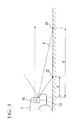
- FIG. 3 is an explanatory diagram of a method of calculating the distance to the central point of the detection range, being a side view ahead of the vehicle.
- the screen coordinates of a specific point on the road surface image, and the distance to the point 22 on the road surface corresponding to the screen coordinates correspond one to one. Accordingly, if the screen coordinates of the central point 35 are known, it is possible to obtain a distance B to a point 25 on the road surface corresponding to the central point 35.
- the control device 40 determines the scanning angle - ⁇ 2 to + ⁇ 1 of the radar 10 from the screen coordinates of the start point 34 and the end point 36 of the detection range as shown in FIG. 2A .
- the angle ⁇ 1 made by the direction corresponding to the central point 35 and the direction corresponding to the start point 34 of the detection range is obtained from the screen coordinates of the central point 35 and the screen coordinates of the start point 34.
- the angle ⁇ 2 made by the direction corresponding to the central point 35 and the direction corresponding to the end point 36 of the detection range is obtained from the screen coordinates of the central point 35 and the screen coordinates of the end point 36.
- the control device 40 drives the motor 10a to rotate the radar 10 based on the calculated rotation angle ⁇ .
- the control device 40 drives the radar 10.
- the radar 10 transmits electromagnetic waves parallel to the road surface, and receives reflected waves from objects. Based on the time from transmission to reception, the distances to the objects are detected. Furthermore, the control device 40 instructs the radar to scan based on the calculated scanning angle - ⁇ 2 to + ⁇ 1.
- FIG. 2B is a plan view of the object detection results from the radar.
- the locations of objects detected outside of the range of the scanning angle - ⁇ 2 to + ⁇ 1 are indicated by broken lines.
- a wall 14a on the left side, a wall 15a at the center rear, and a utility pole 16a on the right side are detected at fixed locations.
- the reflection point detecting device 44 shown in FIG. 1 detects a plurality of reflection points of the reflected waves from locations at a predetermined distance B from the camera 20, based on the detection results of the radar 10.
- the predetermined distance B is the distance from the radar 10 to the detection range, and it is possible to employ the distance to the central point of the detection range as a representative.
- the reflection point 14 on the wall 14a and the reflection point 16 on the utility pole 16a are detected as reflection points separated from the radar 10 to the front of the vehicle by the distance B.
- the reflection point-to-point distance computing device 46 as shown in FIG. 1 calculates the distance between the plurality of reflection points.
- the distance C between the reflection point 14 on the wall 14a and the reflection point 16 on the utility pole 16a is calculated.
- the distance C between the two corresponds to the distance between the wall 14a and the utility pole 16a.
- the control device 40 as shown in FIG. 1 compares the distance C between the reflection points calculated by the reflection point-to-point distance computing device 46 with the vehicle width of the vehicle itself registered in advance, and determines whether or not the vehicle itself can pass between the objects. If the distance C between the reflection points is greater than the vehicle width, it determines that it is possible to pass through, and if it is smaller that the vehicle width, it determines that it is not possible to pass through.
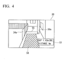
- FIG. 4 is an example of a screen on which the determination results and the like are displayed.
- a display section 51 that displays the determination results and the like from the control device 40 is provided at the corner of the screen of FIG. 4 .
- the display section 51 displays the distance between the objects, the determination result of whether or not it is possible to pass through, and the distance to the objects.
- the distance between the wall 34a and the utility pole 36a is displayed as "Gap 1.92m”
- the determination result of whether or not the vehicle itself can pass through is displayed as "OK”
- the distance from the camera to the central point of the detection range is displayed as "Distance 9m".
- a highlighted display section 55 is provided in which the range set by the occupant for detecting whether or not it is possible to pass through, is displayed in a frame or a band. As a result it can be determined at a glance to which area the display of; the distance between the objects, the determination result of whether or not it is possible to pass through, and the distance to the objects, is related.
- a line display section 58 is provided in which lines corresponding to the vehicle width are displayed from the detection range for whether or not passing through is possible, down to the bottom of the screen. Thereby it is possible to determine at a glance the ratio of the width between the objects and the vehicle width. As a result, the occupant can to estimate the degree of difficulty of passing through.
- the object detecting apparatus 1 is provided with: the radar 10 that receives reflected waves from an object to detect the object by scanning a predetermined scan range using electromagnetic waves; the motor 10a that changes the direction of the radar 10; the camera 20 that captures images; the display 30 that displays an image captured by the camera 20; the touch panel 30a that sets the scan range of the radar 10 on the image displayed on the display 30; and the control device 40 that instructs the motor 10a to rotate the radar 10 based on the scan range, and instructs the radar 10 to scan the scan range.
- the motor that changes the direction of the radar 10 since there is provided the motor that changes the direction of the radar 10, then even in the case where a radar 10 with a narrow scan range is used, it is possible to detect objects in an arbitrary range. Furthermore, since there is provided the touch panel 30a that sets the scan range of the radar 10 on the image displayed, it is possible to set the scan range easily according to the intention of the occupant. Moreover, since there is provided the control device 40 that instructs the motor 10a to rotate the radar 10 based on the set scan range, and instructs the radar 10 to scan the scan range, then even if the scanning location of the laser cannot be observed visually, it is possible to rotate the radar 10 with respect to the set scan range automatically, to scan the scan range.
- the object detecting apparatus 1 is provided with the reflection point detecting device 44 that detects a plurality of reflection points of the reflected waves from locations at a predetermined distance from the camera 20, based on the detection results of the radar 10, and the reflection point-to-point distance computing device 46 that calculates the distance between the plurality of reflection points.
- the object detecting apparatus 1 it is possible to calculate the distance between the plurality of reflection points to obtain the distance between a plurality of objects. As a result it is possible to determine whether or not it is possible for the vehicle itself to pass between the objects.
- the control device 40 determines whether or not the distance between the plurality of reflection points calculated by the reflection point-to-point distance computing device 46 is greater than the vehicle width of the vehicle itself, and displays the result on the display 30. In this case, the occupant can determine at a glance of the display 30 whether or not the distance between the calculated reflection points is greater than the vehicle width of the vehicle itself.
- the control device 40 rotates the radar 10 so that the scanning center of the radar 10 matches the center of the scan range set using the touch panel 30a. In this case, even in the case where a radar 10 with a narrow scan range is used, it is possible to detect objects in a desired range reliably.
- indication of the distances to objects, the gaps between the objects, and the determination result of whether or not it is possible to pass through are not limited to display on a screen. They may be displayed in other places, and may be indicated by sound.
- the above-described display items are one example. Some of the display items may be removed, and other display items may be added.
- An object detecting apparatus can be provided in which objects can be detected in an arbitrary range, and the distance between a plurality of objects can be obtained.
Landscapes
- Engineering & Computer Science (AREA)
- Radar, Positioning & Navigation (AREA)
- Remote Sensing (AREA)
- Physics & Mathematics (AREA)
- Electromagnetism (AREA)
- Computer Networks & Wireless Communication (AREA)
- General Physics & Mathematics (AREA)
- Radar Systems Or Details Thereof (AREA)
- Traffic Control Systems (AREA)
- Geophysics And Detection Of Objects (AREA)
Abstract
Description
- The present invention relates to an object detecting apparatus.
Priority is claimed on Japanese Patent Application No.2007-078790, filed March 26, 2007 - A technique is proposed in which a radar is mounted on a vehicle to detect objects in its surroundings (for example, refer to Patent Document 1).
- Patent Document 1: Japanese Unexamined Patent Application, First Publication No.
H06-294870 - It is hoped that techniques will be developed whereby the distance between a plurality of objects is measured using a radar mounted on a vehicle, to determine if it is possible for the vehicle itself to pass through.
However, the scan range of a laser radar or a millimeter wave radar that can be mounted on a vehicle is typically small, so that it is not possible to detect objects in a wide range using the radar.
If a radar with a wide scan range is used, since it takes time to scan the whole range, the time until an object is detected becomes long. Furthermore, it is difficult from the view of cost, to install two types of radar, namely one with a narrow angular range and one with a wide angular range. - Moreover, realizing wide angle scanning by rotating the laser in addition to the scanning of the laser itself can be considered. In this case, it is necessary to rotate the laser to the central location of the scan range, which is the target. However, since the scanning location of the laser cannot directly be seen visually, it is difficult to rotate the laser to the central location of the scan range manually.
Therefore, the present invention has an object of providing an object detecting apparatus that can detect an object in an arbitrary range, and obtain the distance between a plurality of objects. - In order to solve the above problem, the present invention employs the following. That is, an object detecting apparatus according to the present invention includes: an object detecting device that causes electromagnetic waves to be reflected from an object and receives the reflected waves to detect the object while scanning a predetermined scan range; a rotating device that changes a direction of the object detecting device; an imaging device that captures images; a display device that displays an image captured by the imaging device; a setting device that sets the scan range of the object detecting device on the image displayed by the display device; and a control device that instructs the rotating device to rotate the object detecting device based on the set scan range, and instructs the object detecting device to scan the scan range.
According to the above-described object detecting apparatus, since it has a rotating device that changes the direction of the object detecting device, then even in the case where an object detecting device with a narrow scan range is used, it is possible to detect objects in an arbitrary range. Furthermore, since it has a setting device that sets the scan range of the object detecting device on the image displayed, it is possible to set the scan range easily according to the intention of an operator. Moreover, since it has a control device that instructs the rotating device to rotate the object detecting device, and instructs the object detecting device to scan the scan range, then even if the scanning location of the object detecting device cannot be seen visually, it is possible to rotate the object detecting device with respect to the set scan range automatically, and scan. - It may be arranged such that the object detecting apparatus further includes: a reflection point detecting device that detects a plurality of reflection points of the reflected waves from locations at a predetermined distance from the imaging device, based on a detection result of the object detecting device; and a reflection point-to-point distance computing device that calculates a distance between the plurality of reflection points.
In this case, it is possible to calculate the distance between the plurality of reflection points to obtain the distance between the plurality of objects. - It may be arranged such that the control device determines whether or not the distance calculated by the reflection point-to-point distance computing device is greater than a predetermined value, and instruct the display device to display the result.
In this case, the operator can determine at a glance whether or not the calculated distance is greater than the predetermined value. - It may be arranged such that the control device instructs the rotating device to rotate the object detecting device so that a center of the scan of the object detecting device matches a center of the scan range set by the setting device.
In this case, even in the case where an object detecting device with a narrow scan range is employed, it is possible to detect objects in a desired range reliably. - According to the object detecting apparatus of the present invention, it is possible to detect objects in an arbitrary range, and obtain the distance between a plurality of objects. Furthermore, when detecting the objects, it is possible to set a scan range easily, and automatically scan the set scan range.
-
-
FIG. 1 is a schematic block diagram of an object detecting apparatus according to an embodiment. -
FIG. 2A is an example of an image displayed by a display device. -
FIG. 2B is a plan view of results of object detection by a radar. -
FIG. 3 is an explanatory diagram of a method of calculating a distance from a camera fixed in a vehicle to a central point of a detection range. -
FIG. 4 is an example of a screen on which determination results and the like are displayed. -
- 1
- Object Detecting Apparatus
- 10
- Radar (Object Detecting Device)
- 10a
- Motor (Rotating Device)
- 20
- Camera (Imaging Device)
- 30
- Display (Display Device)
- 30a
- Touch Panel (Setting Device)
- 40
- Control Device
- 44
- Reflection Point Detecting Device
- 46
- Reflection Point-To-Point Distance Computing Device
- Hereunder is a description of an embodiment of the present invention, with reference to the drawings.
-
FIG. 1 is a schematic block diagram of an object detecting apparatus according to the present embodiment. Anobject detecting apparatus 1 according to the present embodiment is mounted on avehicle 5, and is provided with: a radar (object detecting device) 10 that receives reflected waves from an object to detect the object by scanning a predetermined scan range using electromagnetic waves; a camera (imaging device) 20 that captures images; a display (display device) 30 that displays an image captured by thecamera 20; a touch panel (setting device) 30a that sets the scan range of theradar 10 on the image displayed on thedisplay 30; and acontrol device 40 that instructs theradar 10 to scan the set scan range. - The
radar 10, such as a laser radar, a millimeter wave radar, or the like, is mounted on the front of thevehicle 5. Theradar 10 is provided with a transmitting section that transmits electromagnetic waves and a receiving section that receives reflected waves. The transmitting section can scan a predetermined angular range (-α2 to +α1) while transmitting electromagnetic waves forward. The receiving section receives reflected waves that are transmitted from the transmitting section and reflected from objects. - The
radar 10 is mounted on amotor 10a. Themotor 10a is constituted by a stepper motor or the like, and the rotation shaft is arranged in the vertical direction. Themotor 10a mounted on the rotation shaft can rotate in the horizontal plane. InFIG. 1 , theradar 10 rotates only by a rotation angle θ from the vehicle front direction (Rz0 direction), to face in the Rz1 direction. Theradar 10 can scan the range of the scanning angle between -α2 and +α1, centered on the Rz1 direction, using electromagnetic waves. - The
camera 20 such as a CCD camera or the like, is mounted on the front of thevehicle 5. Thecamera 20 captures images ahead of the vehicle.
Thedisplay 30 that displays the images captured by thecamera 20 is mounted in the compartment of thevehicle 5. Atransparent touch panel 30a that can recognize a pressed location, is placed on the surface of thedisplay 30. As a result, by pressing the range that the operator wants to scan, on the image displayed on thedisplay 30, it is possible to set the scan range of theradar 10. - In order to control the operation of the above-mentioned components, a
control device 40 is incorporated in an on-board computer or the like. Thecontrol device 40 calculates the rotation angle θ and the scanning angle -α2 to +α1 of theradar 10, based on the set scan range of theradar 10. To be specific, it calculates the rotation angle θ of theradar 10 from the coordinates of the central point of the scan range, and calculates the scanning angle -α2 to +α1 of theradar 10 from the coordinates of the two end points of the scan range. Then it rotates theradar 10 by the calculated rotation angle θ, and also scans the range of the scanning angle -α2 to +α1 using electromagnetic waves. - Furthermore, the
control device 40 is provided with a reflectionpoint detecting device 44 that detects reflection points of the reflected waves from locations at a predetermined distance from thecamera 20. The reflection point detectingdevice 44 detects a plurality of reflection points existing at a predetermined distance from thecamera 20.
Moreover, thecontrol device 40 is provided with a reflection point-to-pointdistance computing device 46 that calculates the distance between a plurality of reflection points. The distance between the plurality of reflection points corresponds to the gap between the plurality of objects existing ahead of the vehicle. - Furthermore, the
control device 40 compares the distance between the calculated reflection points and the vehicle width of the vehicle itself registered in advance, and determines whether or not the vehicle itself can pass between the objects. Then, thecontrol device 40 displays the calculated distance between the objects and the determination result of whether or not it can pass through, on thedisplay 30. Moreover, thecontrol device 40 displays the predetermined distance on thedisplay 30 as the distance to the objects. - Next is a description of a method of detecting objects using the object detecting apparatus according to the present embodiment.
First, an image ahead of a vehicle is captured by thecamera 20, and the captured image is displayed on thedisplay 30. -
FIG. 2A is an example of an image displayed on the display device. Aset button 31 for a vehicle pass detection range is situated at a corner of the image on thedisplay 30. An occupant of the vehicle presses theset button 31 to set a detection range (that is, the scan range of the radar 10) for determining whether or not the vehicle can pass through. The detection range is set by specifying the detection range on the image using the finger of the occupant. As described above, since thetransparent touch panel 30a is placed on the surface of thedisplay 30, the detection range is set by pressing thetouch panel 30a. The concerned range may be specified by pressing only thestart point 34 and theend point 36 of the detection range. Furthermore, the concerned range may be specified by pressing from thestart point 34 to theend point 36 in a straight line. In the example ofFIG. 2A , with awall 34a on the left side of aroad surface 8 as thestart point 34, and autility pole 36a on the right side as theend point 36, theroad surface 8 between the two is set as the detecting range for determining whether or not the vehicle can pass through. - Next, the
control device 40 calculates the coordinates on the screen (referred to hereunder as "screen coordinates"), of thecentral point 35 of the detection range. The screen coordinates of thecentral point 35 can be calculated from the screen coordinates of thestart point 34 and theend point 36 of the detection range. Next, thecontrol device 40 calculates the distance from thecamera 20 to thecentral point 35 of the detection range.
FIG. 3 is an explanatory diagram of a method of calculating the distance to the central point of the detection range, being a side view ahead of the vehicle. When theroad surface 8 is captured by thecamera 20 fixed in the vehicle, a distance A from thecamera 20 to apoint 22 on the road surface corresponding to thebase point 32 of the image is constant. In this manner, the screen coordinates of a specific point on the road surface image, and the distance to thepoint 22 on the road surface corresponding to the screen coordinates, correspond one to one. Accordingly, if the screen coordinates of thecentral point 35 are known, it is possible to obtain a distance B to apoint 25 on the road surface corresponding to thecentral point 35. - Next, the
control device 40 calculates a rotation angle θ of theradar 10 from the coordinates of thecentral point 35 of the detection range on the screen as shown inFIG 2A (θ=0 in the example ofFIG. 2A ). Since thecamera 20 is fixed on the vehicle, the direction corresponding to the center of the screen is the Rz0 direction ofFIG. 1 , and the direction corresponding to thecentral point 35 of the detection range is the Rz1 direction ofFIG. 1 . Accordingly, the angle made by Rz0 and Rz1 can be obtained from the screen coordinates of the center of the screen and the screen coordinates of thecentral point 35, so that the rotation angle of theradar 10 can be calculated.
Next, thecontrol device 40 determines the scanning angle -α2 to +α1 of theradar 10 from the screen coordinates of thestart point 34 and theend point 36 of the detection range as shown inFIG. 2A . To be specific, the angle α1 made by the direction corresponding to thecentral point 35 and the direction corresponding to thestart point 34 of the detection range is obtained from the screen coordinates of thecentral point 35 and the screen coordinates of thestart point 34. Similarly, the angle α2 made by the direction corresponding to thecentral point 35 and the direction corresponding to theend point 36 of the detection range is obtained from the screen coordinates of thecentral point 35 and the screen coordinates of theend point 36. - The
control device 40 drives themotor 10a to rotate theradar 10 based on the calculated rotation angle θ. Next, thecontrol device 40 drives theradar 10. Theradar 10 transmits electromagnetic waves parallel to the road surface, and receives reflected waves from objects. Based on the time from transmission to reception, the distances to the objects are detected. Furthermore, thecontrol device 40 instructs the radar to scan based on the calculated scanning angle -α2 to +α1. -
FIG. 2B is a plan view of the object detection results from the radar. InFIG. 2B , the locations of objects detected outside of the range of the scanning angle -α2 to +α1 are indicated by broken lines. By scanning by theradar 10, as shown inFIG. 2B , awall 14a on the left side, awall 15a at the center rear, and autility pole 16a on the right side are detected at fixed locations. - Next, the reflection
point detecting device 44 shown inFIG. 1 detects a plurality of reflection points of the reflected waves from locations at a predetermined distance B from thecamera 20, based on the detection results of theradar 10. In the present embodiment, since thecamera 20 and theradar 10 are installed at the same height, reflection points from locations at a predetermined distance B from theradar 10 are detected. The predetermined distance B is the distance from theradar 10 to the detection range, and it is possible to employ the distance to the central point of the detection range as a representative. In the example ofFIG 2B , thereflection point 14 on thewall 14a and thereflection point 16 on theutility pole 16a are detected as reflection points separated from theradar 10 to the front of the vehicle by the distance B. - Next, the reflection point-to-point
distance computing device 46 as shown inFIG. 1 calculates the distance between the plurality of reflection points. In the example ofFIG 2B , the distance C between thereflection point 14 on thewall 14a and thereflection point 16 on theutility pole 16a is calculated. The distance C between the two corresponds to the distance between thewall 14a and theutility pole 16a.
Next, thecontrol device 40 as shown inFIG. 1 compares the distance C between the reflection points calculated by the reflection point-to-pointdistance computing device 46 with the vehicle width of the vehicle itself registered in advance, and determines whether or not the vehicle itself can pass between the objects. If the distance C between the reflection points is greater than the vehicle width, it determines that it is possible to pass through, and if it is smaller that the vehicle width, it determines that it is not possible to pass through. - Next, the
control device 40 displays the determination results and the like of whether or not it is possible to pass through, on the display device.
FIG. 4 is an example of a screen on which the determination results and the like are displayed. Adisplay section 51 that displays the determination results and the like from thecontrol device 40 is provided at the corner of the screen ofFIG. 4 . Thedisplay section 51 displays the distance between the objects, the determination result of whether or not it is possible to pass through, and the distance to the objects. To be specific, the distance between thewall 34a and theutility pole 36a is displayed as "Gap 1.92m", the determination result of whether or not the vehicle itself can pass through is displayed as "OK", and the distance from the camera to the central point of the detection range is displayed as "Distance 9m". - Furthermore, in the image of
FIG. 4 , a highlighteddisplay section 55 is provided in which the range set by the occupant for detecting whether or not it is possible to pass through, is displayed in a frame or a band. As a result it can be determined at a glance to which area the display of; the distance between the objects, the determination result of whether or not it is possible to pass through, and the distance to the objects, is related. Moreover, aline display section 58 is provided in which lines corresponding to the vehicle width are displayed from the detection range for whether or not passing through is possible, down to the bottom of the screen. Thereby it is possible to determine at a glance the ratio of the width between the objects and the vehicle width. As a result, the occupant can to estimate the degree of difficulty of passing through. - As described in detail above, the
object detecting apparatus 1 according to the present embodiment is provided with: theradar 10 that receives reflected waves from an object to detect the object by scanning a predetermined scan range using electromagnetic waves; themotor 10a that changes the direction of theradar 10; thecamera 20 that captures images; thedisplay 30 that displays an image captured by thecamera 20; thetouch panel 30a that sets the scan range of theradar 10 on the image displayed on thedisplay 30; and thecontrol device 40 that instructs themotor 10a to rotate theradar 10 based on the scan range, and instructs theradar 10 to scan the scan range. - According to the above-described
object detecting apparatus 1, since there is provided the motor that changes the direction of theradar 10, then even in the case where aradar 10 with a narrow scan range is used, it is possible to detect objects in an arbitrary range. Furthermore, since there is provided thetouch panel 30a that sets the scan range of theradar 10 on the image displayed, it is possible to set the scan range easily according to the intention of the occupant. Moreover, since there is provided thecontrol device 40 that instructs themotor 10a to rotate theradar 10 based on the set scan range, and instructs theradar 10 to scan the scan range, then even if the scanning location of the laser cannot be observed visually, it is possible to rotate theradar 10 with respect to the set scan range automatically, to scan the scan range. - Furthermore, the
object detecting apparatus 1 according to the present embodiment is provided with the reflectionpoint detecting device 44 that detects a plurality of reflection points of the reflected waves from locations at a predetermined distance from thecamera 20, based on the detection results of theradar 10, and the reflection point-to-pointdistance computing device 46 that calculates the distance between the plurality of reflection points.
According to theobject detecting apparatus 1, it is possible to calculate the distance between the plurality of reflection points to obtain the distance between a plurality of objects. As a result it is possible to determine whether or not it is possible for the vehicle itself to pass between the objects. - Moreover, in the
object detecting apparatus 1 according to the present embodiment, thecontrol device 40 determines whether or not the distance between the plurality of reflection points calculated by the reflection point-to-pointdistance computing device 46 is greater than the vehicle width of the vehicle itself, and displays the result on thedisplay 30.
In this case, the occupant can determine at a glance of thedisplay 30 whether or not the distance between the calculated reflection points is greater than the vehicle width of the vehicle itself. - Furthermore, in the
object detecting apparatus 1 according to the present embodiment, thecontrol device 40 rotates theradar 10 so that the scanning center of theradar 10 matches the center of the scan range set using thetouch panel 30a.
In this case, even in the case where aradar 10 with a narrow scan range is used, it is possible to detect objects in a desired range reliably. - The present invention is not limited to the above-described embodiment.
For example, indication of the distances to objects, the gaps between the objects, and the determination result of whether or not it is possible to pass through, are not limited to display on a screen. They may be displayed in other places, and may be indicated by sound. Moreover, the above-described display items are one example. Some of the display items may be removed, and other display items may be added. - An object detecting apparatus can be provided in which objects can be detected in an arbitrary range, and the distance between a plurality of objects can be obtained.
Claims (4)
- An object detecting apparatus comprising:an object detecting device that causes electromagnetic waves to be reflected from an object and receives the reflected waves to detect said object while scanning a predetermined scan range;a rotating device that changes a direction of said object detecting device;an imaging device that captures images;a display device that displays an image captured by said imaging device;a setting device that sets said scan range of said object detecting device on the image displayed by said display device; anda control device that instructs said rotating device to rotate said object detecting device based on the set scan range, and instructs said object detecting device to scan said scan range.
- The object detecting apparatus according to claim 1, further comprising:a reflection point detecting device that detects a plurality of reflection points of said reflected waves from locations at a predetermined distance from said imaging device, based on a detection result of said object detecting device; anda reflection point-to-point distance computing device that calculates a distance between said plurality of reflection points.
- The object detecting apparatus according to claim 2, wherein said control device determines whether or not said distance calculated by said reflection point-to-point distance computing device is greater than a predetermined value, and instructs said display device to display the result.
- The object detecting apparatus according to claim 1, wherein said control device instructs said rotating device to rotate said object detecting device so that a center of the scan of said object detecting device matches a center of said scan range set by said setting device.
Applications Claiming Priority (2)
| Application Number | Priority Date | Filing Date | Title |
|---|---|---|---|
| JP2007078790A JP5160114B2 (en) | 2007-03-26 | 2007-03-26 | Vehicle passage judgment device |
| PCT/JP2008/054874 WO2008117689A1 (en) | 2007-03-26 | 2008-03-17 | Object detecting apparatus |
Publications (3)
| Publication Number | Publication Date |
|---|---|
| EP2096462A1 true EP2096462A1 (en) | 2009-09-02 |
| EP2096462A4 EP2096462A4 (en) | 2009-12-30 |
| EP2096462B1 EP2096462B1 (en) | 2011-12-28 |
Family
ID=39788425
Family Applications (1)
| Application Number | Title | Priority Date | Filing Date |
|---|---|---|---|
| EP08722269A Not-in-force EP2096462B1 (en) | 2007-03-26 | 2008-03-17 | Object detecting apparatus |
Country Status (5)
| Country | Link |
|---|---|
| US (1) | US8212713B2 (en) |
| EP (1) | EP2096462B1 (en) |
| JP (1) | JP5160114B2 (en) |
| AT (1) | ATE539359T1 (en) |
| WO (1) | WO2008117689A1 (en) |
Families Citing this family (29)
| Publication number | Priority date | Publication date | Assignee | Title |
|---|---|---|---|---|
| JP5518321B2 (en) * | 2008-11-12 | 2014-06-11 | 東日本旅客鉄道株式会社 | Laser radar installation position verification apparatus, laser radar installation position verification method, and laser radar installation position verification apparatus program |
| EP2204671B1 (en) * | 2008-12-30 | 2012-04-11 | Sony Corporation | Camera assisted sensor imaging system and multi aspect imaging system |
| JP2011205513A (en) * | 2010-03-26 | 2011-10-13 | Aisin Seiki Co Ltd | Vehicle periphery monitoring device |
| US8692708B2 (en) * | 2010-03-30 | 2014-04-08 | Sony Corporation | Radiometric imaging device and corresponding method |
| JP2013124968A (en) * | 2011-12-15 | 2013-06-24 | Ihi Aerospace Co Ltd | Automatic range finding apparatus |
| US12462415B2 (en) | 2014-05-06 | 2025-11-04 | Okkola Technologies, Llc | Stationary aerial platform scanning system utilizing measured distances for the construction, displaying terrain features and location of objects |
| US11022681B2 (en) * | 2014-05-06 | 2021-06-01 | Okkola Technologies, Llc | System and method for measuring and rendering terrain on a display |
| US9618611B2 (en) * | 2014-09-24 | 2017-04-11 | Nxp B.V. | Personal radar assistance |
| DE102014014307A1 (en) * | 2014-09-25 | 2016-03-31 | Audi Ag | Method for operating a plurality of radar sensors in a motor vehicle and motor vehicle |
| US10261179B2 (en) | 2016-04-07 | 2019-04-16 | Uhnder, Inc. | Software defined automotive radar |
| US9689967B1 (en) | 2016-04-07 | 2017-06-27 | Uhnder, Inc. | Adaptive transmission and interference cancellation for MIMO radar |
| US9846228B2 (en) | 2016-04-07 | 2017-12-19 | Uhnder, Inc. | Software defined automotive radar systems |
| US9945935B2 (en) | 2016-04-25 | 2018-04-17 | Uhnder, Inc. | Digital frequency modulated continuous wave radar using handcrafted constant envelope modulation |
| US9772397B1 (en) | 2016-04-25 | 2017-09-26 | Uhnder, Inc. | PMCW-PMCW interference mitigation |
| US9954955B2 (en) | 2016-04-25 | 2018-04-24 | Uhnder, Inc. | Vehicle radar system with a shared radar and communication system |
| US9753121B1 (en) | 2016-06-20 | 2017-09-05 | Uhnder, Inc. | Power control for improved near-far performance of radar systems |
| US9971020B1 (en) | 2017-02-10 | 2018-05-15 | Uhnder, Inc. | Radar data buffering |
| WO2018146530A1 (en) | 2017-02-10 | 2018-08-16 | Uhnder, Inc. | Reduced complexity fft-based correlation for automotive radar |
| US11454697B2 (en) | 2017-02-10 | 2022-09-27 | Uhnder, Inc. | Increasing performance of a receive pipeline of a radar with memory optimization |
| WO2018187946A1 (en) * | 2017-04-11 | 2018-10-18 | 深圳市大疆创新科技有限公司 | Radar assembly and unmanned aerial vehicle |
| US11105890B2 (en) | 2017-12-14 | 2021-08-31 | Uhnder, Inc. | Frequency modulated signal cancellation in variable power mode for radar applications |
| US12386029B2 (en) | 2018-01-29 | 2025-08-12 | Robert Bosch Gmbh | Millimeter wave automotive radar systems |
| US11474225B2 (en) | 2018-11-09 | 2022-10-18 | Uhnder, Inc. | Pulse digital mimo radar system |
| US11681017B2 (en) | 2019-03-12 | 2023-06-20 | Uhnder, Inc. | Method and apparatus for mitigation of low frequency noise in radar systems |
| US11953615B2 (en) | 2020-01-13 | 2024-04-09 | Uhnder Inc. | Method and system for antenna array calibration for cross-coupling and gain/phase variations in radar systems |
| CN113829994B (en) * | 2020-06-08 | 2023-11-21 | 广州汽车集团股份有限公司 | Early warning methods, devices, cars and media based on the sound of sirens outside the car |
| KR102439908B1 (en) | 2020-09-03 | 2022-09-05 | 삼성전기주식회사 | Sensing device |
| WO2023100108A1 (en) | 2021-12-02 | 2023-06-08 | Uhnder, Inc. | Radar system with enhanced processing for increased contrast ratio, improved angular separability and elimination of ghost targets |
| KR102599272B1 (en) * | 2021-12-31 | 2023-11-08 | 현대오토에버 주식회사 | Apparatus and method for measuring road width |
Family Cites Families (30)
| Publication number | Priority date | Publication date | Assignee | Title |
|---|---|---|---|---|
| US3670330A (en) * | 1970-07-06 | 1972-06-13 | Sperry Rand Corp | Radar collision avoidance indicator |
| US3697986A (en) * | 1970-10-23 | 1972-10-10 | Sperry Rand Corp | Collision avoidance system |
| US4562439A (en) * | 1982-12-13 | 1985-12-31 | Ford Aerospace & Communications Corporation | Imaging radar seeker |
| JP2834924B2 (en) * | 1991-12-05 | 1998-12-14 | 三菱電機株式会社 | Vehicle control device |
| JP3263699B2 (en) * | 1992-12-22 | 2002-03-04 | 三菱電機株式会社 | Driving environment monitoring device |
| JPH06294870A (en) | 1993-04-12 | 1994-10-21 | Stanley Electric Co Ltd | Laser radar device for vehicles |
| US5486832A (en) * | 1994-07-01 | 1996-01-23 | Hughes Missile Systems Company | RF sensor and radar for automotive speed and collision avoidance applications |
| JP3212235B2 (en) * | 1995-02-10 | 2001-09-25 | 三菱電機株式会社 | Obstacle detection device for vehicles |
| JP3314623B2 (en) * | 1996-08-12 | 2002-08-12 | トヨタ自動車株式会社 | In-vehicle scanning radar |
| JP3804161B2 (en) * | 1997-03-25 | 2006-08-02 | 日産自動車株式会社 | Automatic parking device and parking guidance device |
| JP3398745B2 (en) * | 1997-08-21 | 2003-04-21 | 三菱電機株式会社 | Automotive radar equipment |
| JP2000147115A (en) * | 1998-11-04 | 2000-05-26 | Toyota Motor Corp | Automotive radar equipment |
| JP3687516B2 (en) * | 1999-01-19 | 2005-08-24 | 株式会社豊田自動織機 | Steering assist device for reversing the vehicle |
| JP3787833B2 (en) * | 1999-11-30 | 2006-06-21 | オムロン株式会社 | Object detection apparatus and method, recording medium, and program |
| US6422508B1 (en) * | 2000-04-05 | 2002-07-23 | Galileo Group, Inc. | System for robotic control of imaging data having a steerable gimbal mounted spectral sensor and methods |
| US6683600B1 (en) | 2000-04-19 | 2004-01-27 | Microsoft Corporation | Adaptive input pen mode selection |
| US20050251018A1 (en) * | 2001-02-13 | 2005-11-10 | Gleman Stuart M | Radio-frequency imaging system for medical and other applications |
| JP2003123196A (en) * | 2001-10-10 | 2003-04-25 | Denso Corp | Vehicle periphery monitoring device and program |
| JP3995500B2 (en) * | 2002-02-27 | 2007-10-24 | 富士通テン株式会社 | Radar device antenna axis adjustment method, radar device, radar device manufacturing method, and radar device antenna axis adjustment device |
| JP3862015B2 (en) * | 2002-10-25 | 2006-12-27 | オムロン株式会社 | Automotive radar equipment |
| KR100471268B1 (en) * | 2002-10-28 | 2005-03-10 | 현대자동차주식회사 | Method for detecting vehicle distance |
| US6878939B2 (en) * | 2003-01-31 | 2005-04-12 | Millivision Technologies | Offset drift compensating flat fielding method and camera used in millimeter wave imaging |
| US6870162B1 (en) * | 2003-01-31 | 2005-03-22 | Millivision, Inc. | Weighted noise compensating method and camera used in millimeter wave imaging |
| US6900438B2 (en) * | 2003-01-31 | 2005-05-31 | Millivision Technologies | Baseline compensating method and camera used in millimeter wave imaging |
| JP4281485B2 (en) * | 2003-09-11 | 2009-06-17 | トヨタ自動車株式会社 | Start-up control device for collision damage mitigation device and sensor used therefor |
| JP2006151125A (en) * | 2004-11-26 | 2006-06-15 | Omron Corp | In-vehicle image processing device |
| JP2006201013A (en) * | 2005-01-20 | 2006-08-03 | Hitachi Ltd | Automotive radar |
| JP2006221498A (en) * | 2005-02-14 | 2006-08-24 | Hitachi Ltd | Driving assistance device |
| JP4598653B2 (en) * | 2005-05-13 | 2010-12-15 | 本田技研工業株式会社 | Collision prediction device |
| JP2006323693A (en) * | 2005-05-19 | 2006-11-30 | Olympus Corp | Processor, and method and program for processing image |
-
2007
- 2007-03-26 JP JP2007078790A patent/JP5160114B2/en not_active Expired - Fee Related
-
2008
- 2008-03-17 EP EP08722269A patent/EP2096462B1/en not_active Not-in-force
- 2008-03-17 AT AT08722269T patent/ATE539359T1/en active
- 2008-03-17 WO PCT/JP2008/054874 patent/WO2008117689A1/en not_active Ceased
- 2008-03-17 US US12/522,884 patent/US8212713B2/en not_active Expired - Fee Related
Also Published As
| Publication number | Publication date |
|---|---|
| EP2096462B1 (en) | 2011-12-28 |
| ATE539359T1 (en) | 2012-01-15 |
| JP5160114B2 (en) | 2013-03-13 |
| EP2096462A4 (en) | 2009-12-30 |
| JP2008241304A (en) | 2008-10-09 |
| WO2008117689A1 (en) | 2008-10-02 |
| US20100090880A1 (en) | 2010-04-15 |
| US8212713B2 (en) | 2012-07-03 |
Similar Documents
| Publication | Publication Date | Title |
|---|---|---|
| US8212713B2 (en) | Object detecting apparatus | |
| EP1441318B1 (en) | Security system | |
| CN101641612B (en) | Millimetric wave imaging device and picked-up image display | |
| US7379389B2 (en) | Apparatus for monitoring surroundings of vehicle and sensor unit | |
| KR100352423B1 (en) | Vehicle distance measuring device | |
| EP3185046B1 (en) | Portable backscatter imaging inspection apparatus and imaging method | |
| JP5505702B2 (en) | Vehicle periphery monitoring device | |
| JP6291866B2 (en) | Driving support device and driving support method | |
| US20100066516A1 (en) | Image displaying in-vehicle system, image displaying control in-vehicle apparatus and computer readable medium comprising program for the same | |
| US11231716B2 (en) | Method and apparatus for determining trailer dimensions in a motor vehicle | |
| JP2014235040A (en) | Radar system and target capturing/tracking method | |
| KR101558586B1 (en) | VEHICLE VIDEO DISPLAY AND METHOD | |
| JP2005236540A (en) | In-vehicle camera device | |
| US11237673B2 (en) | Operation detection device and operation detection method | |
| JP2019188855A (en) | Visual confirmation device for vehicle | |
| JP2005338941A (en) | Visibility detection method and visibility detection device | |
| KR20100040822A (en) | System for enforcing illegal parking/stop vehicle | |
| JPH0511052A (en) | Vehicle mounted type obstacle detecting apparatus | |
| JP2013124968A (en) | Automatic range finding apparatus | |
| EP4641257A1 (en) | Two-dimensional scan sensor | |
| JPH11296788A (en) | Vehicle speed measurement device | |
| JP2007043318A (en) | Vehicle surrounding monitoring apparatus and vehicle surrounding monitoring method | |
| EP3546293A1 (en) | Surrounding monitoring device | |
| KR101544790B1 (en) | Apparatus of detecting object of the vehicle and control method thereof | |
| JP2002131422A (en) | Two-dimensional radar device |
Legal Events
| Date | Code | Title | Description |
|---|---|---|---|
| PUAI | Public reference made under article 153(3) epc to a published international application that has entered the european phase |
Free format text: ORIGINAL CODE: 0009012 |
|
| 17P | Request for examination filed |
Effective date: 20090708 |
|
| AK | Designated contracting states |
Kind code of ref document: A1 Designated state(s): AT BE BG CH CY CZ DE DK EE ES FI FR GB GR HR HU IE IS IT LI LT LU LV MC MT NL NO PL PT RO SE SI SK TR |
|
| A4 | Supplementary search report drawn up and despatched |
Effective date: 20091201 |
|
| 17Q | First examination report despatched |
Effective date: 20091211 |
|
| DAX | Request for extension of the european patent (deleted) | ||
| GRAP | Despatch of communication of intention to grant a patent |
Free format text: ORIGINAL CODE: EPIDOSNIGR1 |
|
| RIC1 | Information provided on ipc code assigned before grant |
Ipc: G01S 13/93 20060101ALI20110713BHEP Ipc: G01S 13/86 20060101AFI20110713BHEP |
|
| GRAS | Grant fee paid |
Free format text: ORIGINAL CODE: EPIDOSNIGR3 |
|
| GRAA | (expected) grant |
Free format text: ORIGINAL CODE: 0009210 |
|
| AK | Designated contracting states |
Kind code of ref document: B1 Designated state(s): AT BE BG CH CY CZ DE DK EE ES FI FR GB GR HR HU IE IS IT LI LT LU LV MC MT NL NO PL PT RO SE SI SK TR |
|
| REG | Reference to a national code |
Ref country code: GB Ref legal event code: FG4D |
|
| REG | Reference to a national code |
Ref country code: CH Ref legal event code: EP |
|
| REG | Reference to a national code |
Ref country code: AT Ref legal event code: REF Ref document number: 539359 Country of ref document: AT Kind code of ref document: T Effective date: 20120115 |
|
| REG | Reference to a national code |
Ref country code: IE Ref legal event code: FG4D |
|
| REG | Reference to a national code |
Ref country code: DE Ref legal event code: R096 Ref document number: 602008012340 Country of ref document: DE Effective date: 20120308 |
|
| REG | Reference to a national code |
Ref country code: NL Ref legal event code: VDEP Effective date: 20111228 |
|
| PG25 | Lapsed in a contracting state [announced via postgrant information from national office to epo] |
Ref country code: LT Free format text: LAPSE BECAUSE OF FAILURE TO SUBMIT A TRANSLATION OF THE DESCRIPTION OR TO PAY THE FEE WITHIN THE PRESCRIBED TIME-LIMIT Effective date: 20111228 Ref country code: NO Free format text: LAPSE BECAUSE OF FAILURE TO SUBMIT A TRANSLATION OF THE DESCRIPTION OR TO PAY THE FEE WITHIN THE PRESCRIBED TIME-LIMIT Effective date: 20120328 |
|
| LTIE | Lt: invalidation of european patent or patent extension |
Effective date: 20111228 |
|
| PG25 | Lapsed in a contracting state [announced via postgrant information from national office to epo] |
Ref country code: HR Free format text: LAPSE BECAUSE OF FAILURE TO SUBMIT A TRANSLATION OF THE DESCRIPTION OR TO PAY THE FEE WITHIN THE PRESCRIBED TIME-LIMIT Effective date: 20111228 Ref country code: SE Free format text: LAPSE BECAUSE OF FAILURE TO SUBMIT A TRANSLATION OF THE DESCRIPTION OR TO PAY THE FEE WITHIN THE PRESCRIBED TIME-LIMIT Effective date: 20111228 Ref country code: LV Free format text: LAPSE BECAUSE OF FAILURE TO SUBMIT A TRANSLATION OF THE DESCRIPTION OR TO PAY THE FEE WITHIN THE PRESCRIBED TIME-LIMIT Effective date: 20111228 Ref country code: GR Free format text: LAPSE BECAUSE OF FAILURE TO SUBMIT A TRANSLATION OF THE DESCRIPTION OR TO PAY THE FEE WITHIN THE PRESCRIBED TIME-LIMIT Effective date: 20120329 Ref country code: SI Free format text: LAPSE BECAUSE OF FAILURE TO SUBMIT A TRANSLATION OF THE DESCRIPTION OR TO PAY THE FEE WITHIN THE PRESCRIBED TIME-LIMIT Effective date: 20111228 |
|
| PGFP | Annual fee paid to national office [announced via postgrant information from national office to epo] |
Ref country code: DE Payment date: 20120131 Year of fee payment: 5 |
|
| PG25 | Lapsed in a contracting state [announced via postgrant information from national office to epo] |
Ref country code: BE Free format text: LAPSE BECAUSE OF FAILURE TO SUBMIT A TRANSLATION OF THE DESCRIPTION OR TO PAY THE FEE WITHIN THE PRESCRIBED TIME-LIMIT Effective date: 20111228 Ref country code: CY Free format text: LAPSE BECAUSE OF FAILURE TO SUBMIT A TRANSLATION OF THE DESCRIPTION OR TO PAY THE FEE WITHIN THE PRESCRIBED TIME-LIMIT Effective date: 20111228 |
|
| PG25 | Lapsed in a contracting state [announced via postgrant information from national office to epo] |
Ref country code: BG Free format text: LAPSE BECAUSE OF FAILURE TO SUBMIT A TRANSLATION OF THE DESCRIPTION OR TO PAY THE FEE WITHIN THE PRESCRIBED TIME-LIMIT Effective date: 20120328 Ref country code: IS Free format text: LAPSE BECAUSE OF FAILURE TO SUBMIT A TRANSLATION OF THE DESCRIPTION OR TO PAY THE FEE WITHIN THE PRESCRIBED TIME-LIMIT Effective date: 20120428 Ref country code: SK Free format text: LAPSE BECAUSE OF FAILURE TO SUBMIT A TRANSLATION OF THE DESCRIPTION OR TO PAY THE FEE WITHIN THE PRESCRIBED TIME-LIMIT Effective date: 20111228 Ref country code: NL Free format text: LAPSE BECAUSE OF FAILURE TO SUBMIT A TRANSLATION OF THE DESCRIPTION OR TO PAY THE FEE WITHIN THE PRESCRIBED TIME-LIMIT Effective date: 20111228 Ref country code: CZ Free format text: LAPSE BECAUSE OF FAILURE TO SUBMIT A TRANSLATION OF THE DESCRIPTION OR TO PAY THE FEE WITHIN THE PRESCRIBED TIME-LIMIT Effective date: 20111228 Ref country code: EE Free format text: LAPSE BECAUSE OF FAILURE TO SUBMIT A TRANSLATION OF THE DESCRIPTION OR TO PAY THE FEE WITHIN THE PRESCRIBED TIME-LIMIT Effective date: 20111228 |
|
| PG25 | Lapsed in a contracting state [announced via postgrant information from national office to epo] |
Ref country code: PL Free format text: LAPSE BECAUSE OF FAILURE TO SUBMIT A TRANSLATION OF THE DESCRIPTION OR TO PAY THE FEE WITHIN THE PRESCRIBED TIME-LIMIT Effective date: 20111228 Ref country code: RO Free format text: LAPSE BECAUSE OF FAILURE TO SUBMIT A TRANSLATION OF THE DESCRIPTION OR TO PAY THE FEE WITHIN THE PRESCRIBED TIME-LIMIT Effective date: 20111228 Ref country code: PT Free format text: LAPSE BECAUSE OF FAILURE TO SUBMIT A TRANSLATION OF THE DESCRIPTION OR TO PAY THE FEE WITHIN THE PRESCRIBED TIME-LIMIT Effective date: 20120430 |
|
| PGFP | Annual fee paid to national office [announced via postgrant information from national office to epo] |
Ref country code: FR Payment date: 20120413 Year of fee payment: 5 |
|
| REG | Reference to a national code |
Ref country code: AT Ref legal event code: MK05 Ref document number: 539359 Country of ref document: AT Kind code of ref document: T Effective date: 20111228 |
|
| PG25 | Lapsed in a contracting state [announced via postgrant information from national office to epo] |
Ref country code: DK Free format text: LAPSE BECAUSE OF FAILURE TO SUBMIT A TRANSLATION OF THE DESCRIPTION OR TO PAY THE FEE WITHIN THE PRESCRIBED TIME-LIMIT Effective date: 20111228 Ref country code: MC Free format text: LAPSE BECAUSE OF NON-PAYMENT OF DUE FEES Effective date: 20120331 |
|
| REG | Reference to a national code |
Ref country code: CH Ref legal event code: PL |
|
| PLBE | No opposition filed within time limit |
Free format text: ORIGINAL CODE: 0009261 |
|
| STAA | Information on the status of an ep patent application or granted ep patent |
Free format text: STATUS: NO OPPOSITION FILED WITHIN TIME LIMIT |
|
| GBPC | Gb: european patent ceased through non-payment of renewal fee |
Effective date: 20120328 |
|
| PG25 | Lapsed in a contracting state [announced via postgrant information from national office to epo] |
Ref country code: IT Free format text: LAPSE BECAUSE OF FAILURE TO SUBMIT A TRANSLATION OF THE DESCRIPTION OR TO PAY THE FEE WITHIN THE PRESCRIBED TIME-LIMIT Effective date: 20111228 |
|
| 26N | No opposition filed |
Effective date: 20121001 |
|
| REG | Reference to a national code |
Ref country code: IE Ref legal event code: MM4A |
|
| REG | Reference to a national code |
Ref country code: DE Ref legal event code: R097 Ref document number: 602008012340 Country of ref document: DE Effective date: 20121001 |
|
| PG25 | Lapsed in a contracting state [announced via postgrant information from national office to epo] |
Ref country code: CH Free format text: LAPSE BECAUSE OF NON-PAYMENT OF DUE FEES Effective date: 20120331 Ref country code: LI Free format text: LAPSE BECAUSE OF NON-PAYMENT OF DUE FEES Effective date: 20120331 Ref country code: IE Free format text: LAPSE BECAUSE OF NON-PAYMENT OF DUE FEES Effective date: 20120317 Ref country code: GB Free format text: LAPSE BECAUSE OF NON-PAYMENT OF DUE FEES Effective date: 20120328 Ref country code: AT Free format text: LAPSE BECAUSE OF FAILURE TO SUBMIT A TRANSLATION OF THE DESCRIPTION OR TO PAY THE FEE WITHIN THE PRESCRIBED TIME-LIMIT Effective date: 20111228 |
|
| PG25 | Lapsed in a contracting state [announced via postgrant information from national office to epo] |
Ref country code: ES Free format text: LAPSE BECAUSE OF FAILURE TO SUBMIT A TRANSLATION OF THE DESCRIPTION OR TO PAY THE FEE WITHIN THE PRESCRIBED TIME-LIMIT Effective date: 20120408 |
|
| PG25 | Lapsed in a contracting state [announced via postgrant information from national office to epo] |
Ref country code: FI Free format text: LAPSE BECAUSE OF FAILURE TO SUBMIT A TRANSLATION OF THE DESCRIPTION OR TO PAY THE FEE WITHIN THE PRESCRIBED TIME-LIMIT Effective date: 20111228 |
|
| PG25 | Lapsed in a contracting state [announced via postgrant information from national office to epo] |
Ref country code: MT Free format text: LAPSE BECAUSE OF FAILURE TO SUBMIT A TRANSLATION OF THE DESCRIPTION OR TO PAY THE FEE WITHIN THE PRESCRIBED TIME-LIMIT Effective date: 20111228 |
|
| REG | Reference to a national code |
Ref country code: FR Ref legal event code: ST Effective date: 20131129 |
|
| REG | Reference to a national code |
Ref country code: DE Ref legal event code: R119 Ref document number: 602008012340 Country of ref document: DE Effective date: 20131001 |
|
| PG25 | Lapsed in a contracting state [announced via postgrant information from national office to epo] |
Ref country code: FR Free format text: LAPSE BECAUSE OF NON-PAYMENT OF DUE FEES Effective date: 20130402 Ref country code: DE Free format text: LAPSE BECAUSE OF NON-PAYMENT OF DUE FEES Effective date: 20131001 |
|
| PG25 | Lapsed in a contracting state [announced via postgrant information from national office to epo] |
Ref country code: TR Free format text: LAPSE BECAUSE OF FAILURE TO SUBMIT A TRANSLATION OF THE DESCRIPTION OR TO PAY THE FEE WITHIN THE PRESCRIBED TIME-LIMIT Effective date: 20111228 |
|
| PG25 | Lapsed in a contracting state [announced via postgrant information from national office to epo] |
Ref country code: LU Free format text: LAPSE BECAUSE OF NON-PAYMENT OF DUE FEES Effective date: 20120317 |
|
| PG25 | Lapsed in a contracting state [announced via postgrant information from national office to epo] |
Ref country code: HU Free format text: LAPSE BECAUSE OF FAILURE TO SUBMIT A TRANSLATION OF THE DESCRIPTION OR TO PAY THE FEE WITHIN THE PRESCRIBED TIME-LIMIT Effective date: 20080317 |