EP2096064A2 - Dokumentenzuführungsvorrichtung - Google Patents
Dokumentenzuführungsvorrichtung Download PDFInfo
- Publication number
- EP2096064A2 EP2096064A2 EP09002765A EP09002765A EP2096064A2 EP 2096064 A2 EP2096064 A2 EP 2096064A2 EP 09002765 A EP09002765 A EP 09002765A EP 09002765 A EP09002765 A EP 09002765A EP 2096064 A2 EP2096064 A2 EP 2096064A2
- Authority
- EP
- European Patent Office
- Prior art keywords
- document
- flap
- feeding
- tray
- documents
- Prior art date
- Legal status (The legal status is an assumption and is not a legal conclusion. Google has not performed a legal analysis and makes no representation as to the accuracy of the status listed.)
- Granted
Links
- 230000007246 mechanism Effects 0.000 claims abstract description 56
- 238000011144 upstream manufacturing Methods 0.000 claims abstract description 44
- 230000007306 turnover Effects 0.000 claims abstract description 38
- 239000011521 glass Substances 0.000 description 18
- 238000000926 separation method Methods 0.000 description 14
- 230000004048 modification Effects 0.000 description 8
- 238000012986 modification Methods 0.000 description 8
- 238000005452 bending Methods 0.000 description 3
- 238000000034 method Methods 0.000 description 3
- 230000009471 action Effects 0.000 description 2
- 238000010586 diagram Methods 0.000 description 2
- 230000000694 effects Effects 0.000 description 2
- 230000004044 response Effects 0.000 description 2
- 239000012780 transparent material Substances 0.000 description 2
- 230000008859 change Effects 0.000 description 1
- 230000014509 gene expression Effects 0.000 description 1
- 230000002093 peripheral effect Effects 0.000 description 1
- 238000004904 shortening Methods 0.000 description 1
Images




Classifications
-
- B—PERFORMING OPERATIONS; TRANSPORTING
- B65—CONVEYING; PACKING; STORING; HANDLING THIN OR FILAMENTARY MATERIAL
- B65H—HANDLING THIN OR FILAMENTARY MATERIAL, e.g. SHEETS, WEBS, CABLES
- B65H31/00—Pile receivers
- B65H31/02—Pile receivers with stationary end support against which pile accumulates
-
- H—ELECTRICITY
- H04—ELECTRIC COMMUNICATION TECHNIQUE
- H04N—PICTORIAL COMMUNICATION, e.g. TELEVISION
- H04N1/00—Scanning, transmission or reproduction of documents or the like, e.g. facsimile transmission; Details thereof
- H04N1/00567—Handling of original or reproduction media, e.g. cutting, separating, stacking
- H04N1/0057—Conveying sheets before or after scanning
-
- H—ELECTRICITY
- H04—ELECTRIC COMMUNICATION TECHNIQUE
- H04N—PICTORIAL COMMUNICATION, e.g. TELEVISION
- H04N1/00—Scanning, transmission or reproduction of documents or the like, e.g. facsimile transmission; Details thereof
- H04N1/00567—Handling of original or reproduction media, e.g. cutting, separating, stacking
- H04N1/0057—Conveying sheets before or after scanning
- H04N1/00599—Using specific components
- H04N1/00604—Transport trays
-
- H—ELECTRICITY
- H04—ELECTRIC COMMUNICATION TECHNIQUE
- H04N—PICTORIAL COMMUNICATION, e.g. TELEVISION
- H04N1/00—Scanning, transmission or reproduction of documents or the like, e.g. facsimile transmission; Details thereof
- H04N1/00567—Handling of original or reproduction media, e.g. cutting, separating, stacking
- H04N1/0057—Conveying sheets before or after scanning
- H04N1/00599—Using specific components
- H04N1/00612—Path switches
-
- H—ELECTRICITY
- H04—ELECTRIC COMMUNICATION TECHNIQUE
- H04N—PICTORIAL COMMUNICATION, e.g. TELEVISION
- H04N1/00—Scanning, transmission or reproduction of documents or the like, e.g. facsimile transmission; Details thereof
- H04N1/00567—Handling of original or reproduction media, e.g. cutting, separating, stacking
- H04N1/0057—Conveying sheets before or after scanning
- H04N1/00618—Transporting curved sheets or curving sheets during transportation, e.g. for feeding to a drum-type scanner
-
- H—ELECTRICITY
- H04—ELECTRIC COMMUNICATION TECHNIQUE
- H04N—PICTORIAL COMMUNICATION, e.g. TELEVISION
- H04N1/00—Scanning, transmission or reproduction of documents or the like, e.g. facsimile transmission; Details thereof
- H04N1/00567—Handling of original or reproduction media, e.g. cutting, separating, stacking
- H04N1/0062—Removing sheets from a stack or inputting media
-
- H—ELECTRICITY
- H04—ELECTRIC COMMUNICATION TECHNIQUE
- H04N—PICTORIAL COMMUNICATION, e.g. TELEVISION
- H04N1/00—Scanning, transmission or reproduction of documents or the like, e.g. facsimile transmission; Details thereof
- H04N1/00567—Handling of original or reproduction media, e.g. cutting, separating, stacking
- H04N1/00631—Ejecting or stacking
-
- B—PERFORMING OPERATIONS; TRANSPORTING
- B65—CONVEYING; PACKING; STORING; HANDLING THIN OR FILAMENTARY MATERIAL
- B65H—HANDLING THIN OR FILAMENTARY MATERIAL, e.g. SHEETS, WEBS, CABLES
- B65H2301/00—Handling processes for sheets or webs
- B65H2301/30—Orientation, displacement, position of the handled material
- B65H2301/33—Modifying, selecting, changing orientation
- B65H2301/333—Inverting
- B65H2301/3331—Involving forward reverse transporting means
- B65H2301/33312—Involving forward reverse transporting means forward reverse rollers pairs
-
- B—PERFORMING OPERATIONS; TRANSPORTING
- B65—CONVEYING; PACKING; STORING; HANDLING THIN OR FILAMENTARY MATERIAL
- B65H—HANDLING THIN OR FILAMENTARY MATERIAL, e.g. SHEETS, WEBS, CABLES
- B65H2301/00—Handling processes for sheets or webs
- B65H2301/40—Type of handling process
- B65H2301/42—Piling, depiling, handling piles
- B65H2301/421—Forming a pile
- B65H2301/4212—Forming a pile of articles substantially horizontal
- B65H2301/42124—Forming a pile of articles substantially horizontal by introducing articles selectively from under or above the pile
-
- B—PERFORMING OPERATIONS; TRANSPORTING
- B65—CONVEYING; PACKING; STORING; HANDLING THIN OR FILAMENTARY MATERIAL
- B65H—HANDLING THIN OR FILAMENTARY MATERIAL, e.g. SHEETS, WEBS, CABLES
- B65H2403/00—Power transmission; Driving means
- B65H2403/50—Driving mechanisms
- B65H2403/51—Cam mechanisms
-
- B—PERFORMING OPERATIONS; TRANSPORTING
- B65—CONVEYING; PACKING; STORING; HANDLING THIN OR FILAMENTARY MATERIAL
- B65H—HANDLING THIN OR FILAMENTARY MATERIAL, e.g. SHEETS, WEBS, CABLES
- B65H2404/00—Parts for transporting or guiding the handled material
- B65H2404/10—Rollers
- B65H2404/14—Roller pairs
- B65H2404/142—Roller pairs arranged on movable frame
-
- B—PERFORMING OPERATIONS; TRANSPORTING
- B65—CONVEYING; PACKING; STORING; HANDLING THIN OR FILAMENTARY MATERIAL
- B65H—HANDLING THIN OR FILAMENTARY MATERIAL, e.g. SHEETS, WEBS, CABLES
- B65H2405/00—Parts for holding the handled material
- B65H2405/10—Cassettes, holders, bins, decks, trays, supports or magazines for sheets stacked substantially horizontally
- B65H2405/11—Parts and details thereof
- B65H2405/111—Bottom
- B65H2405/1117—Bottom pivotable, e.g. around an axis perpendicular to transport direction, e.g. arranged at rear side of sheet support
-
- B—PERFORMING OPERATIONS; TRANSPORTING
- B65—CONVEYING; PACKING; STORING; HANDLING THIN OR FILAMENTARY MATERIAL
- B65H—HANDLING THIN OR FILAMENTARY MATERIAL, e.g. SHEETS, WEBS, CABLES
- B65H2801/00—Application field
- B65H2801/03—Image reproduction devices
- B65H2801/06—Office-type machines, e.g. photocopiers
Definitions
- the present invention relates to a document feeding device for feeding a document from a document input tray to a document output tray via a scanning position of a document scanner.
- a document feeding device for feeding a document from a document input tray to a document output tray via a scanning position of a document scanner
- the order of arrangement of documents ejected to (stacked on) the document output tray generally varies depending on whether the scanning mode of the document scanner is single-side scan (scanning one side of each document) or double-side scan (scanning both sides of each document by turning over each document with a turnover mechanism).
- Some of conventional document feeding devices are designed to eject the scanned documents to the document output tray after rearranging the order of the documents by carrying out idle feeding (turning over each document again with the turnover mechanism).
- the idle feeding results in an increase in the time necessary for ejecting each document (i.e. for completing the scanning of each document).
- an automatic document feeding device disclosed in Japanese Patent Provisional Publication No. HEI11-314856 ( Fig. 1 ), for example, is equipped with two separate document output trays (single-side document output tray, double-side document output tray).
- the automatic document feeding device ejects the scanned documents to the single-side document output tray in cases of single-side scan, while ejecting the scanned documents to the double-side document output tray in cases of double-side scan.
- Such an automatic document feeding device is capable of shortening the time necessary for completing the scanning of each document since the aforementioned idle feeding is unnecessary.
- the present invention which has been made in consideration of the above problems, is advantageous in that a document feeding device, capable of ejecting the documents to a common document output tray in the normal arrangement order irrespective of whether the scanning mode is single-side scan or double-side scan without the need of executing the idle feeding, can be provided.
- a document feeding device for feeding documents, comprising a document input tray on which documents to be fed are placed, a document output tray to which the documents are ejected, a feeding mechanism which is provided for a feeding path connecting the document input tray and the document output tray via a scanning position and feeds each document from the document input tray to the scanning position and from the scanning position to the document output tray, a turnover mechanism which is provided for a turnover path connected to the feeding path and returns the document after passing through the scanning position to a position on the upstream side of the scanning position while interchanging the front end and the rear end of the document in a feeding direction, and an ejection mechanism which is configured so that its document ejection mode can be switched between a first ejection mode for successively ejecting each document while stacking it on documents already ejected to the document output tray and a second ejection mode for successively ejecting each document while sliding it under the documents already ejected to the document output tray.
- the document ejection mode can be switched between the first ejection mode for successively ejecting each document while stacking it on the documents already ejected to the document output tray and the second ejection mode for successively ejecting each document while sliding it under the documents already ejected to the document output tray.
- the documents can be ejected to a common document output tray in the normal arrangement order irrespective of whether the scanning mode is single-side scan or double-side scan, without the need of executing the idle feeding. Consequently, the time for the idle feeding of each document becomes unnecessary and the total time necessary for completing the scanning of the documents can be reduced considerably. Further, since the documents can be ejected to one (common) document output tray in the normal arrangement order (irrespective of whether the scanning mode is single-side scan or double-side scan), a great degree of user convenience can be realized.
- the document output tray is equipped with a projecting part which lifts an upstream end of the already ejected documents regarding the feeding direction from the document output tray in the second ejection mode.
- the ejection mechanism includes a pair of ejection rollers which ejects the document to the document output tray and a switching drive mechanism which relatively moves the projecting part and a nipping position of the pair of ejection rollers in a vertical direction.
- the upstream end (in the feeding direction) of the already ejected documents is lifted from the document output tray by the projecting part in the second ejection mode, by which the sliding of each document under the already ejected documents in the second ejection mode is facilitated.
- the projecting part and the nipping position of the pair of ejection rollers are relatively moved in the vertical direction by the switching drive mechanism, by which the positional relationship between the document being ejected and the already ejected document in the vertical direction can be switched and the switching of the document ejection mode between the first ejection mode and the second ejection mode can be implemented.
- the document output tray includes a tray part and a flap part which is attached to the tray part to be pivotable, situated on the upstream side of the tray part in the feeding direction, and equipped with the projecting part.
- the switching drive mechanism pivots the flap part in the vertical direction.
- the flap part of the document output tray (situated on the upstream side of the tray part and equipped with the projecting part) is pivoted in the vertical direction by the switching drive mechanism, by which the switching of the document ejection mode between the first ejection mode and the second ejection mode can be implemented while facilitating the sliding of each document under the already ejected documents in the second ejection mode with the projecting part of the flap part.
- the switching drive mechanism In the document output tray, only the flap part is pivoted up and down by the switching drive mechanism, and thus the load on a motor used for the switching of the document ejection mode can be lessened compared to cases where the whole document output tray is pivoted up and down.
- the ejection rollers can be kept at a fixed position, by which the overall configuration of the ejection mechanism can be simplified compared to cases where the ejection rollers are moved.
- the flap part includes a first flap which is attached to the tray part to be pivotable on the upstream side of the tray part in the feeding direction and a second flap which is attached to the first flap to be pivotable on the upstream side of the first flap in the feeding direction and is equipped with a bent part.
- the bent part of the second flap forms the projecting part.
- the bent part relatively sinks with respect to the second flap compared to its relative position in the second ejection mode due to pivoting of the second flap with respect to the first flap.
- the projecting part is formed by the bent part of the second flap when the flap part pivots upward in the second ejection mode, by which the sliding of each document under the already ejected documents in the second ejection mode is facilitated.
- the bent part which has formed the projecting part in the second ejection mode
- the bent part relatively sinks with respect to the second flap due to pivoting of the second flap with respect to the first flap.
- the switching drive mechanism includes a cam which pivots the flap part upward by pushing up a lower surface of the flap part.
- the document ejection mode can be switched between the first ejection mode and the second ejection mode by pivoting the flap part up and down with the cam.
- the switching of the document ejection mode can be conducted automatically by the movement of the cam, by which the user convenience can be enhanced compared to cases where the document ejection mode is switched manually. Since the flap part is pivoted upward by pushing up its lower surface with the cam, the height of the flap part can be changed and adjusted by changing the height of the cam.
- the document feeding device further comprises a supporting member which supports the cam when the cam has pivoted the flap part upward.
- the cam supports the flap part at a position across its top dead center.
- the supporting member is placed so as to support the cam by restricting further rotation of the cam from the position across the top dead center.
- the cam which has pivoted the flap part upward supports the flap part at the position across its top dead center while being supported by the supporting member which restricts further rotation of the cam from the position across the top dead center. Therefore, the documents ejected to the document output tray (flap part) can be supported stably even when numbers of documents are ejected and the weight of the documents on the document output tray (flap part) increases.
- the flap part is kept at the position by the supporting member without the need of constantly driving the cam, by which power consumption can be saved.
- the second flap is supported on the first flap via a pivot shaft.
- the bent part of the second flap is situated on the downstream side of the pivot shaft in the feeding direction. Upward pivoting of the second flap is restricted by a second flap supporting member which is provided on the upstream side of the pivot shaft in the feeding direction.
- the projecting part is formed by the bent part situated on the downstream side of the pivot shaft when the flap part pivots upward in the second ejection mode, by which the sliding of each document under the already ejected documents in the second ejection mode is facilitated.
- the upward pivoting of the second flap (supported on the first flap via the pivot shaft) is restricted by the second flap supporting member even when the number of documents on the document output tray increases and their weight applied to the projecting part of the second flap becomes heavier, by which the documents ejected to the document output tray (flap part) can be supported stably.
- Fig. 1 is a cross-sectional view showing the overall configuration of a document feeding device in accordance with an embodiment of the present invention.
- Fig. 2 is a cross-sectional view showing the configuration of a document feeding unit of the document feeding device.
- the document feeding device 1 of this embodiment mainly includes a document input tray 10, a document output tray 20 and a document feeding unit 30.
- the document input tray 10 as a part on which documents to be scanned (i.e. documents to be fed) are placed, is situated in a lower right part of the document feeding device 1 in Fig. 1 .
- the document output tray 20 as a part on which the documents after being scanned (i.e. after being ejected from the document feeding unit 30) are stacked, is situated above the document input tray 10.
- the detailed configuration of the document output tray 20 will be described later.
- the document feeding unit 30, as a unit for feeding the document from the document input tray 10 to the document output tray 20, is situated to the left of the document input tray 10 and the document output tray 20 in Fig. 1 .
- An outer frame of the document feeding unit 30 includes a body frame 30A and a cover 30B which is rotatable with respect to the body frame 30A around an axis in a lower left part in Fig. 1 .
- a feeding path 31 and a turnover path 32 for feeding the document are formed mainly by the body frame 30A and the cover 30B.
- the feeding path 31 is equipped with a feeding mechanism (explained later) and a part of an ejection mechanism (explained later), while the turnover path 32 is equipped with a turnover mechanism (explained later).
- the traveling direction of the document being fed from the document input tray 10 to the document output tray 20 through the feeding path 31 (indicated by arrows in Fig. 1 ) will be referred to as a "feeding direction”.
- Expressions “upstream side” and “downstream side” in the following explanation mean “upstream side in the feeding direction” and “downstream side in the feeding direction”, respectively.
- the feeding path 31 (formed substantially in a U-shape) is a path connecting the document input tray 10 and the document output tray 20 via a scanning position R.
- the feeding path 31 is made up of an intake path 33, a lower feeding path 34, a curved path 35 and an upper feeding path 36.
- the intake path 33 continuously extends from a loading surface 10A of the document input tray 10 toward the downstream side substantially in a horizontal direction.
- a guide surface is formed by the body frame 30A.
- the lower feeding path 34 includes a sloped part 34A extending from the downstream end of the intake path 33 toward the lower left in Fig. 2 and a horizontal part 34B extending downstream substantially in a horizontal direction from the downstream end of the sloped part 34A.
- a lower guide surface of the sloped part 34A is formed by the body frame 30A, while an upper guide surface of the sloped part 34A and the horizontal part 34B is formed by a document guide 37.
- the bottom of the horizontal part 34B is open (as the scanning position R) so as to expose the document for the scanning.
- the document guide 37 mainly includes a sloped part and a horizontal part corresponding to the sloped part 34A and the horizontal part 34B of the lower feeding path 34.
- the horizontal part of the document guide 37 holds down the document being exposed at the scanning position R.
- platen glass G of a document scanner (unshown) of a well-known type is provided under the horizontal part of the document guide 37.
- a scan target surface of the document, fed to the scanning position R through the horizontal part 34B while being sandwiched between the document guide 37 and the platen glass G, is scanned by an unshown document scanning unit (e.g. image sensor) placed beneath the platen glass G.
- an unshown document scanning unit e.g. image sensor
- the curved path 35 extending upward like an arc from the downstream end of the lower feeding path 34 (horizontal part 34B), changes the feeding direction by approximately 180 degrees (leftward to rightward in Fig. 2 ).
- a guide surface is formed by the body frame 30A and the cover 30B.
- a part of the curved path 35 can be exposed by rotating and opening the cover 30B, through which a document jammed in the feeding path 31 can be removed.
- a guide surface 35A sloping from a position under the upper edge of the downstream end of the platen glass G toward a nipping position of a second feeding roller 47 and a pinch roller 48 (explained later), is formed at the bottom of the curved path 35 at its upstream end, by which the document being fed on the platen glass G is smoothly fed to the curved path 35 without getting snagged.
- the upper feeding path 36 extends from the downstream end of the curved path 35 toward the document output tray 20.
- an upper guide surface is formed by the body frame 30A, while a lower guide surface is formed by the body frame 30A and a first guide member 61 which will be explained later.
- the downstream end of the upper feeding path 36 serves as a document outlet 38.
- the turnover path 32 extends from the document outlet 38 toward the lower left in Fig. 2 to connect to the upstream end of the lower feeding path 34 (sloped part 34A).
- guide surfaces are formed by the body frame 30A, the first guide member 61 (explained later) and a second guide member 62 (explained later).
- the feeding path 31 is equipped with the feeding mechanism, which feeds the document from the document input tray 10 to the scanning position R, and to the document output tray 20.
- the feeding mechanism is mainly composed of an intake roller 41, an intake pad 42, a separation roller 43, a separation pad 44, a first feeding roller 45, the second feeding roller 47, a switchback roller 50 and pinch rollers 46, 48, 49 and 51.
- the intake roller 41 for pulling the documents placed on the document input tray 10 toward the separation roller 43, is situated to expose its top from the bottom of the intake path 33 at a position near the midpoint of the intake path 33.
- the intake roller 41 is driven and rotated by driving force transmitted from an unshown motor.
- the intake pad 42 for pressing the documents against the intake roller 41 to let the intake roller 41 pull the documents steadily, is situated to face the intake roller 41 from above.
- the intake pad 42 capable of pivoting up and down, is constantly biased toward the intake roller 41.
- the separation roller 43 for sending out the documents one by one, is situated to expose its top from the bottom of the intake path 33 at the downstream end of the intake path 33.
- the separation roller 43 is driven and rotated by driving force transmitted from the unshown motor.
- the separation pad 44 for pressing the documents against the separation roller 43 to let the separation roller 43 separate and send out a document with reliability, is situated to face the separation roller 43 from above.
- the separation pad 44 capable of pivoting up and down, is constantly biased toward the separation roller 43.
- the first feeding roller 45 for feeding the document inside the feeding path 31, is situated to expose its bottom from the top of the lower feeding path 34 (sloped part 34A) at a position near the midpoint of the sloped part 34A while exposing its top from the bottom of the upper feeding path 36 at a position near the midpoint of the upper feeding path 36.
- the first feeding roller 45 is driven and rotated by driving force transmitted from the unshown motor.
- the pinch roller 46 is situated at a position near the midpoint of the sloped part 34A, with its top (exposed from the bottom of the sloped part 34A) contacting the first feeding roller 45.
- the second feeding roller 47 for feeding the document from the scanning position R toward the document output tray 20, is situated to expose its bottom from the top of the curved path 35 at a position near the upstream end of the curved path 35.
- the second feeding roller 47 is driven and rotated by driving force transmitted from the unshown motor.
- the pinch roller 48 is situated at a position near the upstream end of the curved path 35, with its top (exposed from the bottom of the curved path 35) contacting the second feeding roller 47.
- the pinch roller 49 is situated at a position near the midpoint of the upper feeding path 36, with its bottom (exposed from the top of the upper feeding path 36) contacting the first feeding roller 45.
- the switchback roller 50 for ejecting the document to the document output tray 20, is situated at the document outlet 38.
- the switchback roller 50 is driven and rotated by driving force transmitted from the unshown motor.
- the switchback roller 50 forms a part of the turnover mechanism (explained later) and the ejection mechanism (explained later).
- the pinch roller 51 is situated at the document outlet 38 to contact the switchback roller 50 from above. At both ends of the pinch roller 51 in its axial direction, a plurality of projections 51A, for pushing out the document (to be ejected) by making contact with the rear end of the document in the feeding direction, are formed around the periphery of the pinch roller 51.
- the pinch rollers 46, 48, 49 and 51 are biased by unshown biasing members toward the corresponding rollers 45, 47, 45 and 50, respectively, the document can be pressed against the rollers 45, 47 and 50, by which the document can be fed with reliability.
- the turnover path 32 is equipped with the turnover mechanism.
- the turnover mechanism returns the document from the document outlet 38 to a position on the upstream side of the scanning position R (specifically, to a position on the upstream side of the lower feeding path 34 (sloped part 34A) while interchanging the front end and the rear end of the document in the feeding direction (and turning over the document).
- the turnover mechanism is mainly composed of the first guide member 61, the second guide member 62, the switchback roller 50 and a pinch roller 52.
- the first guide member 61 which is situated at a position near the document outlet 38 and on the upstream side of the switchback roller 50, is capable of pivoting up and down around a pivot shaft 61A.
- the first guide member 61 stays downward (as indicated with solid lines in Fig. 2 ) and thereby guides the document toward a nipping position of the switchback roller 50 and the pinch roller 51. In this state, the first guide member 61 forms a part of the lower guide surface of the upper feeding path 36.
- the first guide member 61 first pivots upward (as indicated with chain lines in Fig. 2 ) to change the course of the upper feeding path 36, and thereby guides the document toward a nipping position of the switchback roller 50 and the pinch roller 52. After the whole document has entered the turnover path 32, the first guide member 61 pivots downward (as indicated with solid lines in Fig. 2 ) to form a part of the guide surface of the turnover path 32.
- the second guide member 62 which is situated at the intersection of the turnover path 32 and the feeding path 31 (lower feeding path 34), is capable of pivoting up and down around a pivot shaft 62A.
- the second guide member 62 pivots downward (as indicated with chain lines in Fig. 2 ) and thereby connects the turnover path 32 to the lower feeding path 34.
- the second guide member 62 forms a part of the guide surface of the turnover path 32.
- the second guide member 62 stays upward (as indicated with solid lines in Fig. 2 ) to connect the intake path 33 to the lower feeding path 34.
- the switchback roller 50 is controlled by a well-known control method so that its rotational direction can be changed.
- the switchback roller 50 is driven and rotated counterclockwise in Fig. 2 so as to temporarily feed the document (sandwiched between the switchback roller 50 and the pinch roller 52) toward the outside.
- the rotation of the switchback roller 50 is stopped according to the well-known control method.
- the switchback roller 50 is driven and rotated clockwise in Fig. 2 so as to pull in the document sandwiched between the switchback roller 50 and the pinch roller 52.
- the document pulled in is guided to the turnover path 32 along the lower surface of the first guide member 61.
- the pinch roller 52 is situated in a lower part of the document outlet 38 to contact the switchback roller 50 from below.
- the pinch roller 52 which is also biased toward the switchback roller 50 similarly to the pinch roller 51 on the other side, is capable of pressing the document against the switchback roller 50, by which the document can be fed steadily.
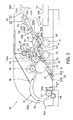
- FIG. 3 is a cross-sectional view showing the operation of the document feeding unit 30 for the single-side scan.
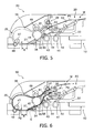
- Figs. 4 - 6 are cross-sectional views showing the operation of the document feeding unit 30 for the double-side scan.
- the document feeding device 1 is equipped with an unshown operation panel, etc., through which the user can specify the single-side scan or the double-side scan.
- the operation panel may also be provided on an image scanning device (scanner, MFP, copier, etc.) in which the document feeding device 1 is installed.
- the first guide member 61 stays at the lower position and the second guide member 62 stays at the upper position as shown in Fig. 3 .
- a document M placed on the document input tray 10 with its scan target surface P1 facing downward is pulled toward the separation roller 43 by the intake roller 41 and the intake pad 42 and then fed to the lower feeding path 34 by the separation roller 43 and the separation pad 44.
- the document M in the lower feeding path 34 is fed by the first feeding roller 45 and the pinch roller 46 to the scanning position R with its scan target surface P1 facing downward.
- the scan target surface P1 of the document M is scanned by a well-known document scanner.
- the document M is fed through the curved path 35 and the upper feeding path 36 by the rollers 47, 48, 45 and 49 and then ejected through the document outlet 38 by the switchback roller 50 and the pinch roller 51.
- the document M Since the document M is ejected with its scan target surface P1 facing upward in this case (single-side scan), the scan target surfaces P1 of already ejected documents (if any) are also facing upward. Therefore, the documents ejected can be arranged in the normal order by successively ejecting each document M while sliding it under the already ejected documents. The ejection mechanism for sliding each document M under the already ejected documents will be described later.
- the first guide member 61 and the second guide member 62 first stay at the upper positions as shown in Fig. 4 .
- a document M placed on the document input tray 10 with its front scan target surface P1 facing downward and its back scan target surface P2 facing upward is fed to the lower feeding path 34 by the rollers 41 and 43 and the pads 42 and 44.
- the document M in the lower feeding path 34 is fed by the first feeding roller 45 and the pinch roller 46 to the scanning position R with its front scan target surface P1 facing downward, at which the front scan target surface P1 of the document M is scanned. Thereafter, the document M is fed through the curved path 35 and the upper feeding path 36 by the rollers 47, 48, 45 and 49, guided under the first guide member 61, and fed toward the outside by the switchback roller 50 and the pinch roller 52.
- the switchback roller 50 By stopping the switchback roller 50 (by the well-known control method) before the document M is totally ejected by the switchback roller 50 and the pinch roller 52, the document M barely remains inside with its rear end sandwiched between the switchback roller 50 and the pinch roller 52 as shown in Fig. 5 . Then, by pivoting both the first guide member 61 and the second guide member 62 downward, the turnover path 32 is formed and connected to the lower feeding path 34. In this state, the front scan target surface P1 and the back scan target surface P2 of the document M are facing upward and downward, respectively.
- the document M is pulled into the turnover path 32 by the switchback roller 50 and the pinch roller 52 and is fed to the upstream part of the lower feeding path 34 (on the upstream side of the scanning position R). Then, the document M is fed by the first feeding roller 45 and the pinch roller 46 to the scanning position R with its back scan target surface P2 facing downward, at which the back scan target surface P2 of the document M is scanned. Thereafter, the document M is fed through the curved path 35 and the upper feeding path 36 by the rollers 47, 48, 45 and 49 and then ejected through the document outlet 38 by the switchback roller 50 and the pinch roller 51.
- the document M Since the document M is ejected with its back scan target surface P2 facing upward in this case (double-side scan), the back scan target surfaces P2 of already ejected documents (if any) are also facing upward. Therefore, the documents ejected can be arranged in the normal order by successively ejecting each document M while stacking it on the already ejected documents. In cases where the upstream end E of the document output tray 20 is situated above the nipping position of the switchback roller 50 and the pinch roller 51 as shown in Fig. 6 , the document M can be stacked on the already ejected documents by just ejecting the document M, by which the documents ejected can be arranged in the normal order.
- Fig. 7 is a schematic diagram showing a flap part and cams of the ejection mechanism viewed in the direction of arrow X in Fig. 2 .
- the direction orthogonal to the sheet of Fig. 2 that is, the width direction of the document (orthogonal to the feeding direction) will be referred to simply as a "width direction”.
- the ejection mechanism is mainly composed of the document output tray 20, the switchback roller 50 and the pinch roller 51 (as an example of a pair of ejection rollers), and cams 53 (as an example of a switching drive mechanism).
- the document output tray 20 is mainly composed of a tray part 21 and a flap part 22 situated on the upstream side of the tray part 21.
- the tray part 21 is situated over the loading surface 10A of the document input tray 10, with its both edges regarding the width direction fixed to side panels 30C.
- the upper surface of the tray part 21 serves as a stacking surface 21 A on which the documents ejected are stacked up.
- the side panels 30C which are placed on both sides of the tray part 21 in the width direction integrally with the body frame 30A, are panel-like members forming the outer frame (housing) of the document feeding device 1 together with the body frame 30A and the cover 30B (see Fig. 1 , in which only one side panel 30C is shown).
- the flap part 22 includes a first flap 23 and a second flap 24.
- the first flap 23 is attached to the tray part 21 to be capable of pivoting up and down around a pivot shaft 23A at its downstream end.
- the first flap 23 has a shaft bearing part 23B at its upstream end.
- contacting parts 23C In upper parts of side faces of the first flap 23 on both sides in the width direction, contacting parts 23C (with which the cams 53 (push-up parts 53C) which will be explained later make contact, respectively) are formed to protrude outward in the width direction (see Fig. 7 ).
- the second flap 24 is situated on the upstream side of the first flap 23.
- the second flap 24 is attached to the first flap 23 to be capable of pivoting around a pivot shaft 24A which is borne by the shaft bearing part 23B of the first flap 23.
- the second flap 24, having a bent part 25 bending downward on the downstream side, is shaped like an "L" overall. Incidentally, downward pivoting of the second flap 24 is restricted within a prescribed range by a stopper 23D (formed at the downstream end of the first flap 23) which makes contact with the lower surface of the second flap 24.
- the switchback roller 50 For ejecting the document, the switchback roller 50 is driven and rotated clockwise in Fig. 2 , by which the document is fed between the switchback roller 50 and the pinch roller 51 and ejected to the document output tray 20.
- the cams 53 are provided on both sides of the first flap 23 in the width direction as shown in Fig. 7 .
- Each cam 53 is integrally formed by a shaft part 53A, a link part 53B and a push-up part 53C.
- the shaft part 53A which is attached to the side panel 30C to be rotatable, is driven and rotated by driving force transmitted from the unshown motor.
- the link part 53B for linking the shaft part 53A with the push-up part 53C, is substantially in parallel with the side panel 30C.
- the push-up part 53C is a substantially cylindrical part which extends inward in the width direction from the distal end of the link part 53B.
- Figs. 8 - 11 are partial cross-sectional views for explaining the operation of the cams 53 and the document output tray 20 of the document feeding device 1.
- Fig. 12A is a cross-sectional view showing a state of the document feeding device 1 in a second ejection mode.
- Fig. 12B is a cross-sectional view showing a state of the document feeding device 1 in a first ejection mode.
- each cam 53 is driven and rotated counterclockwise in Fig. 8 by the driving force transmitted from the unshown motor, by which the push-up part 53C of each cam 53 pivots upward around the shaft part 53A and then makes contact with the lower surface of the contacting part 23C of the first flap 23.
- the contacting part 23C is pushed up as shown in Fig. 9 , by which the flap part 22 (first flap 23) is pivoted upward around the pivot shaft 23A.
- the flap part 22 first flap 23
- the flap part 22 keeps pivoting upward until the push-up part 53C reaches its highest position (corresponding to the top dead center of the cam 53) as shown in Fig. 10 .
- the upstream end 24B of the second flap 24 pivots downward around the pivot shaft 24A as shown in Fig. 9 due to its own weight. Due to the downward pivoting of the second flap 24 (upstream end 24B), the apex of the bent part 25 relatively projects upward and thereby forms a projecting part 25A (as the uppermost part of the second flap 24) as shown in Fig. 10 .
- the downward pivoting of the second flap 24 (upstream end 24B) is restricted when the lower surface of the second flap 24 makes contact with the stopper 23D.
- each cam 53 (push-up part 53C) continues rotating counterclockwise in Fig. 11 across the top dead center (the position shown in Fig. 10 ).
- the counterclockwise rotation of each cam 53 is restricted when its link part 53B makes contact with each supporting member 54 protruding inward in the width direction from each side panel 30C (only one of the two side panels 30C is shown in Fig. 11 ), by which the cams 53 are stopped.
- the documents ejected to the document output tray 20 can be supported stably even when numbers of documents are ejected and the weight W of the documents on the document output tray 20 (flap part 22) increases.
- the flap part 22 is kept at the position by the supporting members 54 without the need of constantly driving the cams 53, by which power consumption can be saved.
- the shaft part 53A of each cam 53 is driven and rotated clockwise in Fig. 11 by the driving force transmitted from the unshown motor, by which the push-up part 53C (which has supported the contacting part 23C of the first flap 23) pivots downward around the shaft part 53A, by which the flap part 22 (first flap 23) pivots downward around the pivot shaft 23A due to its own weight.
- the upstream end 24B of the second flap 24 pivots upward (relative to the first flap 23) around the pivot shaft 24A, by which the apex of the bent part 25 sinks relatively as shown in Fig. 8 (in which the apex is substantially at the same level as the upper surface of the second flap 24 on the upstream side of the apex).
- a document M ejected is placed on the document output tray 20 (the second flap 24, the first flap 23 and the tray part 21) as shown in Fig. 12B .
- the upstream end of the document M is situated below the nipping position of the switchback roller 50 and the pinch roller 51.
- the next document M2 fed by the switchback roller 50 and the pinch roller 51 is ejected while being stacked (placed) on the document M.
- the document ejection mode can be switched between the first ejection mode (for ejecting each document M2 while stacking it on the already ejected documents M) and the second ejection mode (for ejecting each document M2 while sliding it under the already ejected documents M) by use of the cams 53 and the document output tray 20.
- the documents can be ejected to a common document output tray 20 in the normal arrangement order (specifically, with the scan target surfaces of the documents arranged in the normal order) irrespective of whether the scanning mode is single-side scan or double-side scan, without the need of executing the aforementioned idle feeding. Consequently, the time for the idle feeding of each document becomes unnecessary and the total time necessary for completing the scanning of the documents can be reduced considerably. Further, since the documents can be ejected to one (common) document output tray 20 in the normal arrangement order (irrespective of whether the scanning mode is single-side scan or double-side scan), a great degree of user convenience can be realized.
- the switching of the document ejection mode can be conducted automatically by the movement of the cams 53, by which the user convenience can be enhanced compared to cases where the document ejection mode is switched manually.
- the flap part 22 is pivoted up and down.
- the load on the motor for driving the cams 53 can be lessened compared to cases where the whole document output tray is pivoted up and down.
- the switchback roller 50 can be kept at a fixed position, by which the overall configuration of the ejection mechanism can be simplified compared to cases where the switchback roller 50 is moved.
- the flap part 22 is pivoted upward by pushing up its lower surface (i.e. the contacting parts 23C of the first flap 23) with the cams 53.
- the height of the flap part 22 can be changed and adjusted by changing the height of the cams 53 (i.e. the height of the push-up parts 53C).
- the document M at the scanning position R is fed from the center to the downstream end of the platen glass G (from right to left in Fig. 3 ) as shown in Fig. 3 , etc. in the document feeding device 1 of this embodiment.
- the platen glass G (scanning glass) of the document feeding device can be formed by a sheet of glass (transparent material).
- the document M is fed in the opposite direction (from the left end toward the center of the platen glass G) in the configuration of Fig. 3 , the document M shoots into a gap between the upper surface of the platen glass G and the lower surface of the document feeding device 1 and the feeding of the document M to the document output tray situated to the upper right (the document input tray 10 in this embodiment) becomes impossible.
- the platen glass G has to be separated into two at a position to the right of the scanning position R and a sloped surface (with its lower end situated slightly below the upper surface of the platen glass G and its upper end situated to the upper right) has to be provided between the two sheets of platen glass G so that the document M can be fed to the document output tray situated to the upper right without letting the document M shoot into the gap between the upper surface of the platen glass G and the lower surface of the document feeding device 1. While the platen glass G has to be separated into two in cases where the document M is fed in such a direction (opposite to that in Fig.
- the document M is fed in the feeding direction shown in Fig. 3 in the document feeding device 1 of this embodiment, by which the platen glass G can be formed by a sheet of glass (transparent material) and the document scanner can be downsized. Consequently, miniaturization of the device (scanner, MFP, copier, etc.) in which the document feeding device 1 is installed can be realized.
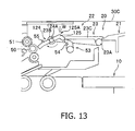
- Fig. 13 is a partial cross-sectional view showing a modification of the configuration of the document feeding device 1.
- a pivot shaft 124A to be borne by the shaft bearing part 23B of the first flap 23 is formed approximately in the middle of a second flap 124, and a bent part 125 of the second flap 124 is formed on the downstream side of the pivot shaft 124A.
- each side panel 30C is provided with a second flap supporting member 55 in a substantially cylindrical shape protruding inward in the width direction.
- the second flap 124 tends to rotate clockwise in Fig. 13 around the pivot shaft 124A.
- the upper surface of the second flap 124 makes contact with the second flap supporting members 55 and the rotation is prohibited, by which the second flap 124 is allowed to stably support the documents.
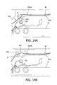
- Figs. 14A and 14B are partial cross-sectional views showing a modification of the switching drive mechanism.
- the switching drive mechanism is capable of moving a switchback roller 250 between the position shown in Fig. 14A (for contacting the pinch roller 51 from below) and the position shown in Fig. 14B (for contacting the pinch roller 51 from above).
- the upstream end of the documents M already ejected to a document output tray 220 is lifted from the document output tray 220 by a projecting part 225A.
- the nipping position of the switchback roller 250 and the pinch roller 51 is situated below the projecting part 225A.
- the nipping position of the switchback roller 250 and the pinch roller 51 is substantially at the same level as the projecting part 225A.
- the next document M2 (fed obliquely upward by the rollers 250 and 51) passes above the upstream end of the documents M and is ejected while being stacked on the documents M.
- the document output tray 20 is placed above the document input tray 10 in the document feeding device I of the above embodiment, the positional relationship of the trays 10 and 20 is not particularly restricted; the present invention is applicable also to configurations in which the document output tray is placed below the document input tray.
- the configuration of the feeding mechanism and the turnover mechanism described in the above embodiment is just an example, and thus the configuration (e.g. the number, arrangement, etc. of the rollers) can be changed properly as needed. It is also possible to employ a pinch roller instead of each pad. In short, the configuration, employed members, etc. of the feeding mechanism and the turnover mechanism may be changed properly without departing from the scope of the present invention.
- the configuration of the feeding path 31 and the turnover path 32 described in the above embodiment is just an example, and thus the configuration is not to be restricted to that in the above embodiment.
- the configuration of the feeding path 31 and the turnover path 32 (or the configuration of the feeding mechanism and the turnover mechanism) may be changed properly depending on the positional relationship between the document input tray and the document output tray, the shape, size, etc. of the document feeding unit, etc.
Landscapes
- Engineering & Computer Science (AREA)
- Multimedia (AREA)
- Signal Processing (AREA)
- Mechanical Engineering (AREA)
- Pile Receivers (AREA)
- Conveyance By Endless Belt Conveyors (AREA)
- Facsimiles In General (AREA)
- Exposure Or Original Feeding In Electrophotography (AREA)
- Delivering By Means Of Belts And Rollers (AREA)
Applications Claiming Priority (1)
| Application Number | Priority Date | Filing Date | Title |
|---|---|---|---|
| JP2008050027A JP4492714B2 (ja) | 2008-02-29 | 2008-02-29 | 原稿搬送装置 |
Publications (3)
| Publication Number | Publication Date |
|---|---|
| EP2096064A2 true EP2096064A2 (de) | 2009-09-02 |
| EP2096064A3 EP2096064A3 (de) | 2012-02-08 |
| EP2096064B1 EP2096064B1 (de) | 2015-05-13 |
Family
ID=40780662
Family Applications (1)
| Application Number | Title | Priority Date | Filing Date |
|---|---|---|---|
| EP20090002765 Ceased EP2096064B1 (de) | 2008-02-29 | 2009-02-26 | Dokumentenzuführungsvorrichtung |
Country Status (4)
| Country | Link |
|---|---|
| US (1) | US8224227B2 (de) |
| EP (1) | EP2096064B1 (de) |
| JP (1) | JP4492714B2 (de) |
| CN (1) | CN101520622B (de) |
Cited By (1)
| Publication number | Priority date | Publication date | Assignee | Title |
|---|---|---|---|---|
| EP2177464A3 (de) * | 2008-09-26 | 2012-02-08 | Brother Kogyo Kabushiki Kaisha | Dokumentzuführer und Dokumentabtastvorrichtung damit |
Families Citing this family (1)
| Publication number | Priority date | Publication date | Assignee | Title |
|---|---|---|---|---|
| JP6819043B2 (ja) * | 2016-01-18 | 2021-01-27 | ブラザー工業株式会社 | シート搬送装置 |
Citations (1)
| Publication number | Priority date | Publication date | Assignee | Title |
|---|---|---|---|---|
| JPH01314856A (ja) | 1988-06-15 | 1989-12-20 | Sanyo Electric Co Ltd | 分離型冷凍装置 |
Family Cites Families (12)
| Publication number | Priority date | Publication date | Assignee | Title |
|---|---|---|---|---|
| JP3488725B2 (ja) | 1993-06-25 | 2004-01-19 | ミサワホーム株式会社 | アルミニウム製構造柱に組み付けられる昇降式ベッド装置及び昇降式収納装置 |
| DE19609435A1 (de) * | 1995-03-10 | 1996-09-19 | Ricoh Kk | Umkehrpfad für eine automatische Zuführeinrichtung für einen Bilderzeugungsapparat |
| US6042103A (en) * | 1997-11-25 | 2000-03-28 | Hewlett-Packard | Printing media pick apparatus and method |
| JPH11314856A (ja) | 1998-05-06 | 1999-11-16 | Mita Ind Co Ltd | 自動原稿搬送装置 |
| US6095517A (en) * | 1998-10-02 | 2000-08-01 | Xerox Corporation | 1-N and N-1 cut sheet receiving and stacking apparatus |
| JP2001058739A (ja) * | 1999-08-20 | 2001-03-06 | Minolta Co Ltd | シート整列装置 |
| JP2001106408A (ja) * | 1999-10-05 | 2001-04-17 | Sharp Corp | シート体排出装置及びシート体排出方法 |
| US6350072B1 (en) * | 2000-02-24 | 2002-02-26 | Xerox Corporation | Printer with plural mode integral module for document handling print output and print duplex inversion |
| JP2005012444A (ja) * | 2003-06-18 | 2005-01-13 | Canon Inc | 自動原稿送り装置 |
| JP4516894B2 (ja) * | 2004-09-17 | 2010-08-04 | 株式会社リコー | 自動原稿搬送装置およびそれを備えた画像形成装置並びに画像読取装置 |
| JP2006232460A (ja) | 2005-02-24 | 2006-09-07 | Ricoh Co Ltd | 原稿自動送り装置 |
| JP4165544B2 (ja) * | 2005-09-26 | 2008-10-15 | ブラザー工業株式会社 | シート材搬送装置 |
-
2008
- 2008-02-29 JP JP2008050027A patent/JP4492714B2/ja not_active Expired - Fee Related
-
2009
- 2009-02-26 EP EP20090002765 patent/EP2096064B1/de not_active Ceased
- 2009-02-27 CN CN2009100079281A patent/CN101520622B/zh not_active Expired - Fee Related
- 2009-02-27 US US12/394,427 patent/US8224227B2/en not_active Expired - Fee Related
Patent Citations (1)
| Publication number | Priority date | Publication date | Assignee | Title |
|---|---|---|---|---|
| JPH01314856A (ja) | 1988-06-15 | 1989-12-20 | Sanyo Electric Co Ltd | 分離型冷凍装置 |
Cited By (2)
| Publication number | Priority date | Publication date | Assignee | Title |
|---|---|---|---|---|
| EP2177464A3 (de) * | 2008-09-26 | 2012-02-08 | Brother Kogyo Kabushiki Kaisha | Dokumentzuführer und Dokumentabtastvorrichtung damit |
| US8295757B2 (en) | 2008-09-26 | 2012-10-23 | Brother Kogyo Kabushiki Kaisha | Document feeder and document scanning device provided with the same |
Also Published As
| Publication number | Publication date |
|---|---|
| JP2009207085A (ja) | 2009-09-10 |
| US8224227B2 (en) | 2012-07-17 |
| CN101520622B (zh) | 2011-09-28 |
| US20090220290A1 (en) | 2009-09-03 |
| CN101520622A (zh) | 2009-09-02 |
| EP2096064A3 (de) | 2012-02-08 |
| EP2096064B1 (de) | 2015-05-13 |
| JP4492714B2 (ja) | 2010-06-30 |
Similar Documents
| Publication | Publication Date | Title |
|---|---|---|
| EP2096063B1 (de) | Dokumentenzuführungsvorrichtung | |
| US7938390B2 (en) | Document feeding device | |
| EP2466867B1 (de) | Bilderzeugungsvorrichtung | |
| US7530568B2 (en) | Double-sided document transport device | |
| US7764920B2 (en) | Duplex document feeder | |
| US8295757B2 (en) | Document feeder and document scanning device provided with the same | |
| EP2096066B1 (de) | Dokumentenzuführungsvorrichtung | |
| US8393610B2 (en) | Sheet feeding device and original sheet conveying device with feed-out roller protruded from the sheet tray and friction member applying friction to uppermost sheet | |
| US8224227B2 (en) | Document feeding device | |
| US20060285902A1 (en) | Automatic Document Feeder | |
| JP2019139054A (ja) | 画像形成装置 | |
| US8205876B2 (en) | Sheet ejector and sheet feeder having the same for inserting later-ejected sheets under earlier-ejected sheets | |
| JP5064518B2 (ja) | 自動原稿搬送装置、及びこれを備えた画像形成装置 | |
| US11381695B2 (en) | Image reading apparatus | |
| JP2010228848A (ja) | 用紙送出装置及びこれを用いた原稿送り装置 | |
| US12371295B2 (en) | Sheet processing apparatus and image forming system | |
| US7611145B2 (en) | Automatic document feeder | |
| JP5783776B2 (ja) | シート搬送装置及び原稿情報読取装置 | |
| JP4508933B2 (ja) | シート搬送装置、シート処理装置及び画像形成装置 | |
| JP2012250852A (ja) | 自動原稿搬送装置、及びこれを備えた画像形成装置 |
Legal Events
| Date | Code | Title | Description |
|---|---|---|---|
| PUAI | Public reference made under article 153(3) epc to a published international application that has entered the european phase |
Free format text: ORIGINAL CODE: 0009012 |
|
| AK | Designated contracting states |
Kind code of ref document: A2 Designated state(s): AT BE BG CH CY CZ DE DK EE ES FI FR GB GR HR HU IE IS IT LI LT LU LV MC MK MT NL NO PL PT RO SE SI SK TR |
|
| AX | Request for extension of the european patent |
Extension state: AL BA RS |
|
| PUAL | Search report despatched |
Free format text: ORIGINAL CODE: 0009013 |
|
| AK | Designated contracting states |
Kind code of ref document: A3 Designated state(s): AT BE BG CH CY CZ DE DK EE ES FI FR GB GR HR HU IE IS IT LI LT LU LV MC MK MT NL NO PL PT RO SE SI SK TR |
|
| AX | Request for extension of the european patent |
Extension state: AL BA RS |
|
| RIC1 | Information provided on ipc code assigned before grant |
Ipc: B65H 31/02 20060101AFI20111230BHEP Ipc: H04N 1/00 20060101ALI20111230BHEP |
|
| 17P | Request for examination filed |
Effective date: 20120808 |
|
| AKX | Designation fees paid |
Designated state(s): DE FR GB |
|
| GRAP | Despatch of communication of intention to grant a patent |
Free format text: ORIGINAL CODE: EPIDOSNIGR1 |
|
| INTG | Intention to grant announced |
Effective date: 20141223 |
|
| GRAS | Grant fee paid |
Free format text: ORIGINAL CODE: EPIDOSNIGR3 |
|
| GRAA | (expected) grant |
Free format text: ORIGINAL CODE: 0009210 |
|
| AK | Designated contracting states |
Kind code of ref document: B1 Designated state(s): DE FR GB |
|
| REG | Reference to a national code |
Ref country code: GB Ref legal event code: FG4D |
|
| REG | Reference to a national code |
Ref country code: DE Ref legal event code: R096 Ref document number: 602009031190 Country of ref document: DE Effective date: 20150625 |
|
| REG | Reference to a national code |
Ref country code: FR Ref legal event code: PLFP Year of fee payment: 8 |
|
| REG | Reference to a national code |
Ref country code: DE Ref legal event code: R097 Ref document number: 602009031190 Country of ref document: DE |
|
| PLBE | No opposition filed within time limit |
Free format text: ORIGINAL CODE: 0009261 |
|
| STAA | Information on the status of an ep patent application or granted ep patent |
Free format text: STATUS: NO OPPOSITION FILED WITHIN TIME LIMIT |
|
| 26N | No opposition filed |
Effective date: 20160216 |
|
| REG | Reference to a national code |
Ref country code: FR Ref legal event code: PLFP Year of fee payment: 9 |
|
| REG | Reference to a national code |
Ref country code: FR Ref legal event code: PLFP Year of fee payment: 10 |
|
| PGFP | Annual fee paid to national office [announced via postgrant information from national office to epo] |
Ref country code: FR Payment date: 20230109 Year of fee payment: 15 |
|
| PGFP | Annual fee paid to national office [announced via postgrant information from national office to epo] |
Ref country code: GB Payment date: 20230111 Year of fee payment: 15 Ref country code: DE Payment date: 20230111 Year of fee payment: 15 |
|
| REG | Reference to a national code |
Ref country code: DE Ref legal event code: R119 Ref document number: 602009031190 Country of ref document: DE |
|
| GBPC | Gb: european patent ceased through non-payment of renewal fee |
Effective date: 20240226 |
|
| PG25 | Lapsed in a contracting state [announced via postgrant information from national office to epo] |
Ref country code: DE Free format text: LAPSE BECAUSE OF NON-PAYMENT OF DUE FEES Effective date: 20240903 |
|
| PG25 | Lapsed in a contracting state [announced via postgrant information from national office to epo] |
Ref country code: GB Free format text: LAPSE BECAUSE OF NON-PAYMENT OF DUE FEES Effective date: 20240226 |
|
| PG25 | Lapsed in a contracting state [announced via postgrant information from national office to epo] |
Ref country code: FR Free format text: LAPSE BECAUSE OF NON-PAYMENT OF DUE FEES Effective date: 20240229 |
|
| PG25 | Lapsed in a contracting state [announced via postgrant information from national office to epo] |
Ref country code: GB Free format text: LAPSE BECAUSE OF NON-PAYMENT OF DUE FEES Effective date: 20240226 Ref country code: FR Free format text: LAPSE BECAUSE OF NON-PAYMENT OF DUE FEES Effective date: 20240229 Ref country code: DE Free format text: LAPSE BECAUSE OF NON-PAYMENT OF DUE FEES Effective date: 20240903 |