EP2095902A1 - Arc welding device - Google Patents
Arc welding device Download PDFInfo
- Publication number
- EP2095902A1 EP2095902A1 EP09001500A EP09001500A EP2095902A1 EP 2095902 A1 EP2095902 A1 EP 2095902A1 EP 09001500 A EP09001500 A EP 09001500A EP 09001500 A EP09001500 A EP 09001500A EP 2095902 A1 EP2095902 A1 EP 2095902A1
- Authority
- EP
- European Patent Office
- Prior art keywords
- welding
- control
- power source
- arc
- feed
- Prior art date
- Legal status (The legal status is an assumption and is not a legal conclusion. Google has not performed a legal analysis and makes no representation as to the accuracy of the status listed.)
- Withdrawn
Links
Images
Classifications
-
- B—PERFORMING OPERATIONS; TRANSPORTING
- B23—MACHINE TOOLS; METAL-WORKING NOT OTHERWISE PROVIDED FOR
- B23K—SOLDERING OR UNSOLDERING; WELDING; CLADDING OR PLATING BY SOLDERING OR WELDING; CUTTING BY APPLYING HEAT LOCALLY, e.g. FLAME CUTTING; WORKING BY LASER BEAM
- B23K9/00—Arc welding or cutting
- B23K9/10—Other electric circuits therefor; Protective circuits; Remote controls
- B23K9/1006—Power supply
-
- B—PERFORMING OPERATIONS; TRANSPORTING
- B23—MACHINE TOOLS; METAL-WORKING NOT OTHERWISE PROVIDED FOR
- B23K—SOLDERING OR UNSOLDERING; WELDING; CLADDING OR PLATING BY SOLDERING OR WELDING; CUTTING BY APPLYING HEAT LOCALLY, e.g. FLAME CUTTING; WORKING BY LASER BEAM
- B23K9/00—Arc welding or cutting
- B23K9/10—Other electric circuits therefor; Protective circuits; Remote controls
- B23K9/1093—Consumable electrode or filler wire preheat circuits
-
- B—PERFORMING OPERATIONS; TRANSPORTING
- B23—MACHINE TOOLS; METAL-WORKING NOT OTHERWISE PROVIDED FOR
- B23K—SOLDERING OR UNSOLDERING; WELDING; CLADDING OR PLATING BY SOLDERING OR WELDING; CUTTING BY APPLYING HEAT LOCALLY, e.g. FLAME CUTTING; WORKING BY LASER BEAM
- B23K9/00—Arc welding or cutting
- B23K9/12—Automatic feeding or moving of electrodes or work for spot or seam welding or cutting
- B23K9/133—Means for feeding electrodes, e.g. drums, rolls, motors
-
- B—PERFORMING OPERATIONS; TRANSPORTING
- B23—MACHINE TOOLS; METAL-WORKING NOT OTHERWISE PROVIDED FOR
- B23K—SOLDERING OR UNSOLDERING; WELDING; CLADDING OR PLATING BY SOLDERING OR WELDING; CUTTING BY APPLYING HEAT LOCALLY, e.g. FLAME CUTTING; WORKING BY LASER BEAM
- B23K9/00—Arc welding or cutting
- B23K9/16—Arc welding or cutting making use of shielding gas
- B23K9/167—Arc welding or cutting making use of shielding gas and of a non-consumable electrode
Definitions
- the invention relates to an arc welding apparatus comprising a welding power source, by means of which an arc between a non-consumable electrode and a workpiece can be generated, in particular for TIG and / or plasma welding, and further comprising a feed part for the defined feeding of welding filler material to the workpiece, wherein the feed part a Feed control is assigned to control the feed part.
- an arc can be generated between a non-consumable electrode and a workpiece to be welded.
- the arc acting on the workpiece creates a weld pool for welding the workpiece.
- a filler metal such as a rod electrode or a welding wire, may be supplied to the molten bath.
- the feed takes place by means of a feed part.
- the feed part is controlled by a feed control, so that the filler metal can be supplied automatically depending on the course of the welding process, in particular as a function of the welding speed and / or the quality of the arc.
- the welding power source provides the required electrical energy for the welding process and is usually designed in the form of a manageable unit.
- the feed control forms a second unit in combination with the feed part.
- the two components can be matched.
- connection cable between the welding power source and the feed control can impair the functional reliability of the arc welder. For example, there is a risk of the welder stumbling over the connection cable and breaking the electrical connection.
- adjustment or adjustment of the welding power source and the feed control requires a not inconsiderable amount of time and is a source of danger if the adjustment is not performed carefully by the welder.
- Object of the present invention is to develop an arc welding device of the type mentioned in such a way that it has a simpler handling and improved reliability.
- the welding power source together with the feed part and / or the feed control form a common functional unit. This is easy to handle by the user, since the said components are held on a common support member.
- Such a configuration is particularly suitable for mobile use of the arc welding machine.
- the welding power source and the feed control may be connected to each other at the manufacturer side via a fixed wiring, so that the welder does not need to connect any additional electrical connection cables to connect the electric components of the arc welder with each other.
- An electrical adjustment of the components by the welder can be omitted. Required adjustments can be made by the manufacturer.
- the number of components of the arc welding device which must be manually matched by the user and / or connected to each other, can be significantly reduced.
- the risk of incorrect operation is thereby reduced and thus the reliability is increased.
- the handling of the arc welder simplifies.
- the arc welding device according to the invention can be configured in particular as a TIG welding device (tungsten inert gas, in the English-speaking world tungsten inert gas (TIG)) or in the form of a plasma welding device.
- TIG welding device tungsten inert gas, in the English-speaking world tungsten inert gas (TIG)
- TIG tungsten inert gas
- the welding power source forms together with the feed part and the feed control a common functional unit which is held on or in a support member, wherein conveniently also the supply of welding filler material is arranged on or in the support member.
- the support member forms in an advantageous embodiment of the invention, the housing of the arc welding machine.
- the housing forms a mechanical support both the welding power source and the feed part and / or the feed control.
- the supply of welding filler material is integrated into the housing of the arc welding device or outside of the housing.
- a further simplification of the handling of the arc welding device according to the invention is achieved in a preferred embodiment in that the welding power source and the feed control are jointly assigned to a display and control panel.
- the latter is preferably held on or in the common support member.
- the user can set and read welding process parameters on the display and control panel, with the display and control panel associated with both the welding power source and the feed control.
- the arc welder is designed very clear and can be operated by the user in a simple way.
- the arc welding device has a central control device, which is held on or in the common support member and electrically connected to the welding power source and the feed control.
- the central control device controls the welding process, wherein, for example, the quality of the arc between the non-consumable electrode and the workpiece and also the advancing movement of the welding consumable material can be predetermined by the central control device.
- This is as well as the welding power source and the feed control held on or in the central support member, in particular can be provided be that the central control device is integrated into the housing of the arc welder.
- the arc welding device has a positioning control held on or in the common support part for controlling a workpiece positioning device and / or a welding head positioning device.
- the workpiece positioning device By means of the workpiece positioning device, the workpiece can be moved relative to the non-consumable electrode during the welding process.
- the corresponding control signals are received by the workpiece positioning device from the positioning control of the arc welding device.
- the workpiece positioning device can be designed, for example, in the form of a turntable on which the workpiece to be welded can be positioned and which can be rotated during the welding process.
- a welding head of the arc welding device can be moved relative to the workpiece during the welding process.
- the welding head may comprise a welding torch and / or a positioning unit for positioning the welding filler material on the workpiece. Due to the arrangement of the positioning control on or in the common support part of the arc welding device and the positioning control forms a device component, which forms a single manageable unit together with the welding power source and the feed part and / or the feed control.
- a welding wire is used as the welding filler material and the arc welding device has a controllable heating current source held on or in the common supporting part for heating the free end of the welding wire facing the workpiece.
- the arc supplied to the welding wire is heated by the arc.
- the arc is deprived of energy and thus the welding process is influenced.
- it is advantageous if the free end of the welding wire before it is fed to the arc for example Resistance heating is heated.
- the free end of the welding wire is in this case heated to a high temperature, but without forming an arc between the welding wire and the workpiece and without the welding wire already melts.
- the heating current source has only a low working voltage, so that no arc can form from the free end of the welding wire to the workpiece.
- the Schustrometti forms together with the welding power source, the feed part and / or the feed control and preferably together with the welding wire supply a jointly manageable functional unit, all components on or in the common support member, preferably in a housing of the arc welding device held are. It is thus advantageous if the Schwarzstromario is integrated into the housing of the arc welding machine.
- the common display and control panel which is preferably used are preferably also assigned the central control device, the positioning control and / or the heating current source.
- the central control device, the positioning control and the heating current source each form a device component of the arc welding device.
- These device components can be associated with the common display and control panel, which can be kept as well as the device components mentioned on or in the common support member to form a total of an arc welding device in the form of an easily manageable functional unit.
- the positioning control and / or the heating current source as well as the welding power source and the feed control are electrically connected to the central control device. This makes it possible to easily control the positioning of the workpiece and / or the welding head and the heating of the free end of the welding wire during the welding process by means of the central control device.
- the central control device has at least one central storage element, in which workpiece-specific process parameters of the welding power source, the feed control, the positioning control and / or the Schustromquelle can be stored and retrieved by the user as needed.
- the at least one central memory element gives the possibility of tool-specific process parameters of the welding process save. If a plurality of identical workpieces are to be welded, the optimum welding parameters can be stored in a central storage element during welding of a first workpiece and retrieved by the user for welding further identical workpieces. Thus, for welding processes in which an arc is generated between a non-consumable electrode and a workpiece, a considerable simplification can be achieved.
- technically trained personnel stores the optimum parameters for welding a workpiece in a central storage member and that subsequently, identically designed workpieces are welded by technically less preformed personnel by means of the stored parameters.
- the central control device can form an information processing entity which maintains star-shaped connections to the common display and control panel as well as feed control, the welding power source, the heating current source and the positioning control.
- all these device components can be easily matched and controlled, the device components are integrated together with the central control unit in the housing of the arc welding device and form a single unit.
- the arc welder has a BUS system to which the welding power source, the feed control, the common display and control panel, the central control device, the positioning and / or the Schustromquelle are connected.
- a BUS system for example a CAN bus, facilitates the control of the arc welder and simplifies its construction.
- the common display and control panel has a touch-sensitive screen (touchscreen).
- a gas can be supplied to the non-consumable electrode during the welding process, so that the arc between the non-consumable electrode and the workpiece burns in a special gas atmosphere.
- a protective gas in particular argon, or else a forming gas in the form of a mixture, in particular of nitrogen and hydrogen.
- the supply of the gas during the welding process can be regulated by means of a flow regulator, which is controllable by a gas control device of the arc welding device.
- the gas control device may also be held on or in the common support member.
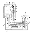
- FIGURE of the drawing shows schematically an arc welding device according to the invention, to which a welding torch and an inert gas reservoir as well as a workpiece and a workpiece positioning device are connected.
- the arc welding device 10 forms a single functional unit, which is designed to be portable in the illustrated embodiment.
- the arc welding device 10 has a housing 12, on the upper side of a carrying handle 14 is fixed.
- the housing 12 forms a supporting part, in which the device components of the arc welding device 10 described in detail below are held.
- a first device component of the arc welding device 10 is a welding power source 16 with a control part 17 and a power section 18.
- a welding power source 16 with a control part 17 and a power section 18.
- a protective gas for example argon
- a gas reservoir 26 can be supplied to the welding torch 22 via a gas line 24.
- a controllable flow regulator 27 is connected in the gas line 24, a controllable flow regulator 27 is connected.
- a second device component which is integrated in the housing 12 of the arc welding device 10 as well as the welding power source 16, is formed by a supply of filler metal, which is configured in the present embodiment as a welding wire 28.
- the welding wire supply 28 may be in the form of a supply drum 29 for welding wire 30.
- the latter can be led out of the housing 12 by means of a feed part 32 and fed to a workpiece 34 to be welded.
- the feed member 32 forms a third device component of the arc welding apparatus 10, which is integrated in the housing 12 and held on this.
- the welding wire supply 28 may also be mounted on the outside of the housing 12, the welding wire 30 being guided through the housing 12 and the advancing part 32.
- An arrangement of the welding wire supply 28 separate from the housing 12 is possible, wherein the welding wire 30 is guided from the supply roll 29 through the housing 12 and the feed member 32 so that it can be supplied from the feed member 32 in a predetermined manner the workpiece 34.
- the feed part 32 is controlled by a feed control 36, which forms a fourth device component of the arc welding device 10 according to the invention and is also integrated in the housing 12.
- the welding power source 16 and the feed control 36 are connected via a bus system 38 to a central control device 40, which forms a further device component of the arc welding device 10 according to the invention and is integrated in the housing 12.
- the BUS system has an interface 39, via which the central control device 40 can be connected to an external control device (not shown in the drawing). This enables external monitoring and logging as well as integration into higher-level automation concepts.
- the interface 39 may be designed in the form of a radio interface or allow the connection of a radio module, so that the arc welding device can be connected via a radio link to an external control device.
- the central control device 40 is connected to a central display and control panel 42 via the BUS system 38. This likewise forms a device component of the arc welding device 10 integrated into the housing 12.
- the workpiece 34 For welding the workpiece 34, this can be connected via a ground line 44 to the power section 18 of the welding power source 16.
- the workpiece 34 can be positioned on a workpiece positioning device 46, which in the illustrated embodiment is designed in the form of a turntable 47, which is rotatable about a vertical axis of rotation 49 by means of a controllable drive unit 48.
- the arc welding device 10 has a device component in the form of a positioning controller 51, which is integrated in the housing 12 and connected to the central control device 40 via the BUS system 38.
- the positioning control 51 is connected to the drive unit 48 of the workpiece positioning device 46 via a first control line 50.
- the orientation of the welding torch 22 relative to the workpiece 34 can also be effected by means of a welding head positioning device 70, which in the present case is designed in the form of a robot arm 71 which is rotatable about several axes and displaceable along several axes.
- a welding head positioning device 70 which in the present case is designed in the form of a robot arm 71 which is rotatable about several axes and displaceable along several axes.
- Such robot arms 71 are known per se to those skilled in the art.
- the control of the Sch bulkkopfpositionier Hughes 70 also takes place by means of the housing 12 integrated in the positioning control 51. This is connected via a second control line 72 to the Sch bulkkopfpositionier coupled 70.
- the welding torch 22 has a non-consumable electrode 54. Between the electrode 54 and the workpiece 34, an arc 56 can be generated by means of the welding power source 16. At the same time, a protective gas can be supplied to the electrode 54 in a regulated manner via the gas line 24, so that the arc 56 burns in a protective gas atmosphere. The application of the workpiece 34 to the arc 56 results in the formation of a molten bath on the workpiece 34.
- Welding wire 30 can be supplied to the molten bath by means of the feed part 32 of the arc welding device 10 controlled by the feed control 36 in response to control signals which the feed control 36 receives from the central control device 40, which also controls the welding power source 16.
- the regulation of the gas flow takes place by means of the flow regulator 27, which is connected in the gas line 24 and is controlled by an integrated into the housing 12 gas control 75.
- the gas control 75 forms another device component of the arc welder, which is built into the housing 12 to achieve a compact design.
- Via a control line 76, the gas control 75 is connected to the flow controller 27.
- the gas control 75 is connected to the BUS system 38 and is thus in electrical communication with the central control device 40.
- the welder 10 By means of the welder 10 different workpieces can be welded.
- the process parameters used for welding the respective workpiece for example the welding current, the welding voltage, the feed rate of the welding wire 30, the movement data of the workpiece positioning device 46 and the welding head positioning device 70, can be specific to the workpiece in a central position
- Memory member 58 of the central controller 40 is stored and retrieved as needed by the user via the display and control panel 42.
- the free end 60 of the welding wire 30 can be preheated by means of a heating current source 62 before it enters the region of the arc 56.
- the heating current source 62 represents a further device component of the arc welding device 10 and is integrated in the housing 12.
- the heating current source 62 is also connected to the BUS system 38 and can thus be controlled by the central control device 40. Via a heating line 64, the heating current source 62 is connected to a wire holding device 66, which is fixed to the Sch specifickopfpositionier nails 70.
- a heating voltage can be applied to the free end 60 of the welding wire 30 via the wire holding device, so that an electrical connection to the workpiece 34 is made starting from the heating current source 62 via the heating line 64 and the free end 60 of the welding wire 30.
- the heating current flowing through the free end 60 heats the free end 60 to a temperature below the melting point of the welding wire 30 so that it virtually no longer draws any energy from the arc 56, and consequently the electrical energy supplied by the welding power source 16 to the non-consumable electrode 54 becomes practical Unchanged for welding the workpiece 34 is available.
- the free end 60 is not preheated by the heating current source 62, then the arc 56 is deprived of energy by supplying the cold welding wire.
- the energy can be removed by supplying additional electrical Energy from the welding power source 16 can be compensated.
- this has the consequence that overall the workpiece 34 is subjected to additional heat. Preheating the free end 60 thus allows the heat load on the workpiece 34 to be reduced.
- the welding device 10 is characterized by easy handling and high functional reliability. This is achieved in particular by the feed control 36, the feed part 32, the positioning control 51, the gas control 75, the heating current source 62 and also the welding wire supply 28 being integrated in the housing 12 in addition to the welding power source 16.
- the welding power source 16 provides the welding energy required to form an arc between the non-consumable electrode 54 and the workpiece 34, and the feed control 36 connected to the welding power source 16 and the central controller 40 via the BUS system 38 provides in combination with the advancing portion 32 and the welding wire supply 28 ensure that the preheated welding wire can be supplied to the arc by means of the heating current source 62 as a function of workpiece-specific process data.
Abstract
Description
Die Erfindung betrifft ein Lichtbogenschweißgerät umfassend eine Schweißstromquelle, mittels derer ein Lichtbogen zwischen einer nicht abschmelzenden Elektrode und einem Werkstück erzeugbar ist, insbesondere zum WIG-und/oder Plasmaschweißen, und außerdem umfassend ein Vorschubteil zum definierten Zuführen von Schweißzusatzwerkstoff zum Werkstück, wobei dem Vorschubteil eine Vorschubsteuerung zum Steuern des Vorschubteiles zugeordnet ist.The invention relates to an arc welding apparatus comprising a welding power source, by means of which an arc between a non-consumable electrode and a workpiece can be generated, in particular for TIG and / or plasma welding, and further comprising a feed part for the defined feeding of welding filler material to the workpiece, wherein the feed part a Feed control is assigned to control the feed part.
Mittels der Schweißstromquelle kann zwischen einer nicht abschmelzenden Elektrode und einem zu schweißenden Werkstück ein Lichtbogen erzeugt werden. Der auf das Werkstück einwirkende Lichtbogen erzeugt ein Schmelzbad zum Verschweißen des Werkstückes. Ein Schweißzusatzwerkstoff, beispielsweise eine Stabelektrode oder ein Schweißdraht, kann dem Schmelzbad zugeführt werden. Die Zuführung erfolgt mittels eines Vorschubteiles. Das Vorschubteil wird von einer Vorschubsteuerung gesteuert, so dass der Schweißzusatzwerkstoff in Abhängigkeit vom Verlauf des Schweißprozesses, insbesondere in Abhängigkeit von der Schweißgeschwindigkeit und/oder der Qualität des Lichtbogens, selbsttätig zugeführt werden kann.By means of the welding power source, an arc can be generated between a non-consumable electrode and a workpiece to be welded. The arc acting on the workpiece creates a weld pool for welding the workpiece. A filler metal, such as a rod electrode or a welding wire, may be supplied to the molten bath. The feed takes place by means of a feed part. The feed part is controlled by a feed control, so that the filler metal can be supplied automatically depending on the course of the welding process, in particular as a function of the welding speed and / or the quality of the arc.
Die Schweißstromquelle stellt die erforderliche elektrische Energie für den Schweißprozess zur Verfügung und ist üblicherweise in Form einer handhabbaren Baueinheit ausgestaltet. Die Vorschubsteuerung bildet in Kombination mit dem Vorschubteil eine zweite Baueinheit aus. Zur Koordination der Schweißstromquelle mit der Vorschubsteuerung werden diese üblicherweise über externe Kabel miteinander elektrisch verbunden, und mittels entsprechender Stellglieder an der Schweißstromquelle und an der Vorschubsteuerung können die beiden Komponenten aufeinander abgestimmt werden.The welding power source provides the required electrical energy for the welding process and is usually designed in the form of a manageable unit. The feed control forms a second unit in combination with the feed part. For the coordination of the welding power source with the feed control they are usually via external cables electrically connected to each other, and by means of corresponding actuators on the welding power source and on the feed control, the two components can be matched.
Das Verbindungskabel zwischen der Schweißstromquelle und der Vorschubsteuerung kann die Funktionssicherheit des Lichtbogenschweißgerätes beeinträchtigen. So besteht beispielsweise die Gefahr, dass der Schweißer über das Verbindungskabel stolpert und die elektrische Verbindung unterbricht. Außerdem erfordert die Abstimmung bzw. das Justieren der Schweißstromquelle und der Vorschubsteuerung einen nicht zu unterschätzenden Zeitaufwand und stellt eine Gefahrenquelle dar, falls die Justierung vom Schweißer nicht sorgfältig durchgeführt wird.The connection cable between the welding power source and the feed control can impair the functional reliability of the arc welder. For example, there is a risk of the welder stumbling over the connection cable and breaking the electrical connection. In addition, the adjustment or adjustment of the welding power source and the feed control requires a not inconsiderable amount of time and is a source of danger if the adjustment is not performed carefully by the welder.
Aufgabe der vorliegenden Erfindung ist es, ein Lichtbogenschweißgerät der eingangs genannten Art derart weiterzubilden, dass es eine einfachere Handhabung und eine verbesserte Funktionssicherheit aufweist.Object of the present invention is to develop an arc welding device of the type mentioned in such a way that it has a simpler handling and improved reliability.
Diese Aufgabe wird bei einem Lichtbogenschweißgerät der eingangs genannten Art erfindungsgemäß dadurch gelöst, dass die Schweißstromquelle zusammen mit dem Vorschubteil und/oder der Vorschubsteuerung an oder in einem gemeinsamen Tragteil gehalten ist.This object is achieved according to the invention in an arc welding device of the type mentioned, that the welding power source is held together with the feed part and / or the feed control on or in a common support member.
Beim erfindungsgemäßen Lichtbogenschweißgerät bildet die Schweißstromquelle zusammen mit dem Vorschubteil und/oder der Vorschubsteuerung eine gemeinsame funktionelle Baueinheit. Diese ist vom Benutzer auf einfache Weise handhabbar, da die genannten Komponenten an einem gemeinsamen Tragteil gehalten sind. Eine derartige Ausgestaltung eignet sich insbesondere für den mobilen Einsatz des Lichtbogenschweißgerätes. Die Schweißstromquelle und die Vorschubsteuerung können herstellerseitig über eine feste Verdrahtung miteinander verbunden sein, so dass der Schweißer keine zusätzlichen elektrischen Verbindungskabel anschließen muss, um die elektrischen Komponenten des Lichtbogenschweißgerätes miteinander zu verbinden. Auch eine elektrische Justierung der Komponenten durch den Schweißer kann entfallen. Erforderliche Justierungen können herstellerseitig erfolgen. Durch die erfindungsgemäße Konstruktion lässt sich die Anzahl der Komponenten des Lichtbogenschweißgerätes, die vom Benutzer manuell aufeinander abgestimmt und/oder miteinander verbunden werden müssen, ganz erheblich reduzieren. Die Gefahr einer Fehlbedienung wird dadurch verringert und somit wird die Funktionssicherheit erhöht. Außerdem vereinfacht sich die Handhabung des Lichtbogenschweißgerätes.In the arc welding apparatus according to the invention, the welding power source together with the feed part and / or the feed control form a common functional unit. This is easy to handle by the user, since the said components are held on a common support member. Such a configuration is particularly suitable for mobile use of the arc welding machine. The welding power source and the feed control may be connected to each other at the manufacturer side via a fixed wiring, so that the welder does not need to connect any additional electrical connection cables to connect the electric components of the arc welder with each other. An electrical adjustment of the components by the welder can be omitted. Required adjustments can be made by the manufacturer. Due to the construction according to the invention, the number of components of the arc welding device, which must be manually matched by the user and / or connected to each other, can be significantly reduced. The risk of incorrect operation is thereby reduced and thus the reliability is increased. In addition, the handling of the arc welder simplifies.
Das erfindungsgemäße Lichtbogenschweißgerät kann insbesondere als WIG-Schweißgerät (Wolfram-Inert-Gas, im englischen Sprachraum Tungsten-Inert-Gas (TIG) genannt) oder in Form eines Plasmaschweißgerätes ausgestaltet sein.The arc welding device according to the invention can be configured in particular as a TIG welding device (tungsten inert gas, in the English-speaking world tungsten inert gas (TIG)) or in the form of a plasma welding device.
Im Hinblick auf eine möglichst kompakte Ausgestaltung ist es von Vorteil, wenn ein Vorrat an Schweißzusatzwerkstoff am oder im gemeinsamen Tragteil gehalten ist.With regard to the most compact design, it is advantageous if a supply of welding filler material is held on or in the common support member.
Bevorzugt bildet die Schweißstromquelle zusammen mit dem Vorschubteil und der Vorschubsteuerung eine gemeinsame funktionelle Einheit, die an oder in einem Tragteil gehalten ist, wobei günstigerweise auch noch der Vorrat an Schweißzusatzwerkstoff am oder im Tragteil angeordnet ist.Preferably, the welding power source forms together with the feed part and the feed control a common functional unit which is held on or in a support member, wherein conveniently also the supply of welding filler material is arranged on or in the support member.
Das Tragteil bildet bei einer vorteilhaften Ausgestaltung der Erfindung das Gehäuse des Lichtbogenschweißgerätes aus. Das Gehäuse bildet eine mechanische Halterung sowohl der Schweißstromquelle als auch des Vorschubteils und/oder der Vorschubsteuerung. Vorzugsweise ist auch der Vorrat an Schweißzusatzwerkstoff in das Gehäuse des Lichtbogenschweißgerätes integriert oder außenseitig am Gehäuse gehalten.The support member forms in an advantageous embodiment of the invention, the housing of the arc welding machine. The housing forms a mechanical support both the welding power source and the feed part and / or the feed control. Preferably, the supply of welding filler material is integrated into the housing of the arc welding device or outside of the housing.
Eine weitere Vereinfachung der Handhabung des erfindungsgemäßen Lichtbogenschweißgerätes wird bei einer bevorzugten Ausführungsform dadurch erzielt, dass der Schweißstromquelle und der Vorschubsteuerung gemeinsam ein Anzeige- und Bedienfeld zugeordnet sind. Letzteres ist bevorzugt am oder im gemeinsamen Tragteil gehalten. Der Benutzer kann Schweißprozessparameter am Anzeige- und Bedienfeld einstellen und ablesen, wobei das Anzeige- und Bedienfeld sowohl der Schweißstromquelle als auch der Vorschubsteuerung zugeordnet ist. Somit ist das Lichtbogenschweißgerät sehr übersichtlich ausgestaltet und kann vom Benutzer auf einfache Weise bedient werden.A further simplification of the handling of the arc welding device according to the invention is achieved in a preferred embodiment in that the welding power source and the feed control are jointly assigned to a display and control panel. The latter is preferably held on or in the common support member. The user can set and read welding process parameters on the display and control panel, with the display and control panel associated with both the welding power source and the feed control. Thus, the arc welder is designed very clear and can be operated by the user in a simple way.
Von besonderem Vorteil ist es, wenn das Lichtbogenschweißgerät eine zentrale Steuereinrichtung aufweist, die am oder im gemeinsamen Tragteil gehalten und mit der Schweißstromquelle und der Vorschubsteuerung elektrisch verbunden ist. Die zentrale Steuereinrichtung steuert den Schweißprozess, wobei zum Beispiel die Qualität des Lichtbogens zwischen der nicht abschmelzenden Elektrode und dem Werkstück und auch die Vorschubbewegung des Schweißzusatzwerkstoffes von der zentralen Steuereinrichtung vorgegeben werden können. Diese ist ebenso wie die Schweißstromquelle und die Vorschubsteuerung am oder im zentralen Tragteil gehalten, insbesondere kann vorgesehen sein, dass die zentrale Steuereinrichtung in das Gehäuse des Lichtbogenschweißgerätes integriert ist.It is particularly advantageous if the arc welding device has a central control device, which is held on or in the common support member and electrically connected to the welding power source and the feed control. The central control device controls the welding process, wherein, for example, the quality of the arc between the non-consumable electrode and the workpiece and also the advancing movement of the welding consumable material can be predetermined by the central control device. This is as well as the welding power source and the feed control held on or in the central support member, in particular can be provided be that the central control device is integrated into the housing of the arc welder.
Günstig ist es, wenn das Lichtbogenschweißgerät eine am oder im gemeinsamen Tragteil gehaltene Positioniersteuerung zur Steuerung einer Werkstückpositioniereinrichtung und/oder einer Schweißkopfpositionseinrichtung aufweist. Mittels der Werkstückpositioniereinrichtung kann das Werkstück relativ zur nicht abschmelzenden Elektrode während des Schweißprozesses bewegt werden. Die entsprechenden Steuersignale erhält die Werkstückpositioniervorrichtung von der Positioniersteuerung des Lichtbogenschweißgerätes. Die Werkstückpositioniereinrichtung kann beispielsweise in Form eines Drehtisches ausgestaltet sein, auf dem das zu schweißende Werkstück positioniert werden kann und der während des Schweißprozesses in Drehung versetzt werden kann. Mittels der Schweißkopfpositioniereinrichtung kann ein Schweißkopf des Lichtbogenschweißgerätes während des Schweißprozesses relativ zum Werkstück bewegt werden. Der Schweißkopf kann einen Schweißbrenner aufweisen und/oder eine Positioniereinheit zur Positionierung des Schweißzusatzwerkstoffes am Werkstück. Durch die Anordnung der Positioniersteuerung am oder im gemeinsamen Tragteil des Lichtbogenschweißgerätes bildet auch die Positioniersteuerung eine Gerätekomponente, die zusammen mit der Schweißstromquelle und dem Vorschubteil und/oder der Vorschubsteuerung eine einzige handhabbare Baueinheit ausbildet.It is advantageous if the arc welding device has a positioning control held on or in the common support part for controlling a workpiece positioning device and / or a welding head positioning device. By means of the workpiece positioning device, the workpiece can be moved relative to the non-consumable electrode during the welding process. The corresponding control signals are received by the workpiece positioning device from the positioning control of the arc welding device. The workpiece positioning device can be designed, for example, in the form of a turntable on which the workpiece to be welded can be positioned and which can be rotated during the welding process. By means of the welding head positioning device, a welding head of the arc welding device can be moved relative to the workpiece during the welding process. The welding head may comprise a welding torch and / or a positioning unit for positioning the welding filler material on the workpiece. Due to the arrangement of the positioning control on or in the common support part of the arc welding device and the positioning control forms a device component, which forms a single manageable unit together with the welding power source and the feed part and / or the feed control.
Von besonderem Vorteil ist es, wenn als Schweißzusatzwerkstoff ein Schweißdraht zum Einsatz kommt und das Lichtbogenschweißgerät eine am oder im gemeinsamen Tragteil gehaltene steuerbare Heizstromquelle aufweist zum Erwärmen des dem Werkstück zugewandten freien Endes des Schweißdrahtes.It is particularly advantageous if a welding wire is used as the welding filler material and the arc welding device has a controllable heating current source held on or in the common supporting part for heating the free end of the welding wire facing the workpiece.
Der dem Lichtbogen zugeführte Schweißdraht wird vom Lichtbogen erwärmt. Dies hat zur Folge, dass dem Lichtbogen Energie entzogen wird und dadurch der Schweißprozess beeinflusst wird. Um den Einfluss des Schweißdrahtes auf die Energiebilanz des Lichtbogens möglichst gering und möglichst konstant zu halten, und zwar selbst dann, wenn die pro Zeiteinheit zugeführte Drahtmenge sich ändert, ist es von Vorteil, wenn der freie Endbereich des Schweißdrahtes vor seiner Zuführung zum Lichtbogen beispielsweise durch Widerstandserwärmung erwärmt wird. Das freie Ende des Schweißdrahtes wird hierbei auf eine hohe Temperatur erwärmt, jedoch ohne dass sich ein Lichtbogen zwischen Schweißdraht und Werkstück ausbildet und ohne dass der Schweißdraht bereits schmilzt. Wird der stark erwärmte Schweißdraht dem Lichtbogen zugeführt, so wird dem Lichtbogen nur sehr wenig Wärme durch den Schweißdraht entzogen und dadurch wird der Einfluss des Schweißdrahtes auf die Qualität des Lichtbogens verringert.The arc supplied to the welding wire is heated by the arc. As a result, the arc is deprived of energy and thus the welding process is influenced. In order to keep the influence of the welding wire on the energy balance of the arc as small as possible and as constant as possible, even if the per unit time supplied amount of wire changes, it is advantageous if the free end of the welding wire before it is fed to the arc, for example Resistance heating is heated. The free end of the welding wire is in this case heated to a high temperature, but without forming an arc between the welding wire and the workpiece and without the welding wire already melts. When the highly heated welding wire is fed to the arc, only little heat is extracted from the arc by the welding wire and this reduces the influence of the welding wire on the quality of the arc.
Zum Erwärmen des freien Endes des Schweißdrahtes kommt eine Heizstromquelle zum Einsatz, die beispielsweise als Konstantstromquelle ausgestaltet sein kann. Die Heizstromquelle weist nur eine geringe Arbeitsspannung auf, so dass sich vom freien Ende des Schweißdrahtes zum Werkstück kein Lichtbogen ausbilden kann.For heating the free end of the welding wire is a Heizstromquelle used, which may be configured for example as a constant current source. The heating current source has only a low working voltage, so that no arc can form from the free end of the welding wire to the workpiece.
Gemäß einer vorteilhaften Ausführungsform der Erfindung bildet die Heizstromquelle zusammen mit der Schweißstromquelle, dem Vorschubteil und/oder der Vorschubsteuerung und vorzugsweise zusammen mit dem Schweißdrahtvorrat eine gemeinsam handhabbare funktionelle Baueinheit, wobei sämtliche Komponenten am oder im gemeinsamen Tragteil, vorzugsweise in einem Gehäuse des Lichtbogenschweißgerätes, gehalten sind. Es ist somit von Vorteil, wenn auch die Heizstromquelle in das Gehäuse des Lichtbogenschweißgerätes integriert ist.According to an advantageous embodiment of the invention, the Heizstromquelle forms together with the welding power source, the feed part and / or the feed control and preferably together with the welding wire supply a jointly manageable functional unit, all components on or in the common support member, preferably in a housing of the arc welding device held are. It is thus advantageous if the Heizstromquelle is integrated into the housing of the arc welding machine.
Dem vorzugsweise zum Einsatz kommenden gemeinsamen Anzeige- und Bedienfeld sind bevorzugt auch die zentrale Steuereinrichtung, die Positioniersteuerung und/oder die Heizstromquelle zugeordnet. Die zentrale Steuereinrichtung, die Positioniersteuerung und die Heizstromquelle bilden jeweils eine Gerätekomponente des Lichtbogenschweißgerätes aus. Diesen Gerätekomponenten kann das gemeinsame Anzeige- und Bedienfeld zugeordnet sein, das ebenso wie die genannten Gerätekomponenten am oder im gemeinsamen Tragteil gehalten sein kann, um insgesamt ein Lichtbogenschweißgerät in Form einer einfach handhabbaren funktionellen Baueinheit auszubilden.The common display and control panel which is preferably used are preferably also assigned the central control device, the positioning control and / or the heating current source. The central control device, the positioning control and the heating current source each form a device component of the arc welding device. These device components can be associated with the common display and control panel, which can be kept as well as the device components mentioned on or in the common support member to form a total of an arc welding device in the form of an easily manageable functional unit.
Von Vorteil ist es, wenn die Positioniersteuerung und/oder die Heizstromquelle ebenso wie die Schweißstromquelle und die Vorschubsteuerung mit der zentralen Steuereinrichtung elektrisch verbunden sind. Dies gibt die Möglichkeit, mittels der zentralen Steuereinrichtung auch die Positionierung des Werkstückes und/oder des Schweißkopfes sowie die Aufheizung des freien Endes des Schweißdrahtes während des Schweißprozesses auf einfache Weise zu steuern.It is advantageous if the positioning control and / or the heating current source as well as the welding power source and the feed control are electrically connected to the central control device. This makes it possible to easily control the positioning of the workpiece and / or the welding head and the heating of the free end of the welding wire during the welding process by means of the central control device.
Bei einer besonders bevorzugten Ausgestaltung weist die zentrale Steuereinrichtung mindestens ein zentrales Speicherglied auf, in dem werkstückspezifische Prozessparameter der Schweißstromquelle, der Vorschubsteuerung, der Positioniersteuerung und/oder der Heizstromquelle speicherbar und bei Bedarf vom Benutzer abrufbar sind. Das mindestens eine zentrale Speicherglied gibt die Möglichkeit, Prozessparameter des Schweißprozesses werkzeugspezifisch abzuspeichern. Sollen mehrere identische Werkstücke geschweißt werden, so können beim Schweißen eines ersten Werkstückes die optimalen Schweißparameter in einem zentralen Speicherglied gespeichert und zum Schweißen weiterer identischer Werkstücke vom Benutzer abgerufen werden. So kann für Schweißverfahren, bei denen ein Lichtbogen zwischen einer nicht abschmelzenden Elektrode und einem Werkstück erzeugt wird, eine beträchtliche Vereinfachung erzielt werden. Insbesondere besteht die Möglichkeit, dass technisch vorgebildetes Personal die zum Schweißen eines Werkstückes optimalen Parameter in einem zentralen Speicherglied speichert und dass anschließend weitere, identisch ausgestaltete Werkstücke von technisch weniger vorgebildetem Personal geschweißt werden mittels der gespeicherten Parameter.In a particularly preferred embodiment, the central control device has at least one central storage element, in which workpiece-specific process parameters of the welding power source, the feed control, the positioning control and / or the Heizstromquelle can be stored and retrieved by the user as needed. The at least one central memory element gives the possibility of tool-specific process parameters of the welding process save. If a plurality of identical workpieces are to be welded, the optimum welding parameters can be stored in a central storage element during welding of a first workpiece and retrieved by the user for welding further identical workpieces. Thus, for welding processes in which an arc is generated between a non-consumable electrode and a workpiece, a considerable simplification can be achieved. In particular, there is the possibility that technically trained personnel stores the optimum parameters for welding a workpiece in a central storage member and that subsequently, identically designed workpieces are welded by technically less preformed personnel by means of the stored parameters.
Die zentrale Steuereinrichtung kann eine Informationsverarbeitungsinstanz ausbilden, welche sternförmig Verbindungen unterhält zum gemeinsamen Anzeige- und Bedienfeld sowie zur Vorschubsteuerung, zur Schweißstromquelle, zur Heizstromquelle und zur Positioniersteuerung. Mittels der zentralen Steuereinrichtung können alle diese Gerätekomponenten auf einfache Weise aufeinander abgestimmt und gesteuert werden, wobei die Gerätekomponenten zusammen mit der zentralen Steuereinheit im Gehäuse des Lichtbogenschweißgerätes integriert sind und eine einzige Baueinheit ausbilden.The central control device can form an information processing entity which maintains star-shaped connections to the common display and control panel as well as feed control, the welding power source, the heating current source and the positioning control. By means of the central control device, all these device components can be easily matched and controlled, the device components are integrated together with the central control unit in the housing of the arc welding device and form a single unit.
Bei einer besonders bevorzugten Ausführungsform weist das Lichtbogenschweißgerät ein BUS-System auf, an dem die Schweißstromquelle, die Vorschubsteuerung, das gemeinsame Anzeige- und Bedienfeld, die zentrale Steuereinrichtung, die Positioniersteuerung und/oder die Heizstromquelle angeschlossen sind. Die Bereitstellung eines BUS-Systems, beispielsweise eines CAN-Busses, erleichtert die Steuerung des Lichtbogenschweißgerätes und vereinfacht dessen Aufbau.In a particularly preferred embodiment, the arc welder has a BUS system to which the welding power source, the feed control, the common display and control panel, the central control device, the positioning and / or the Heizstromquelle are connected. The provision of a BUS system, for example a CAN bus, facilitates the control of the arc welder and simplifies its construction.
Das gemeinsame Anzeige- und Bedienfeld weist bei einer bevorzugten Ausgestaltung einen berührungsempfindlichen Bildschirm (Touchscreen) auf. Dadurch kann die Handhabung des Lichtbogenschweißgerätes zusätzlich vereinfacht werden.In a preferred embodiment, the common display and control panel has a touch-sensitive screen (touchscreen). As a result, the handling of the arc welding device can be additionally simplified.
Es kann vorgesehen sein, dass der nicht abschmelzenden Elektrode während des Schweißprozesses ein Gas zuführbar ist, so dass der Lichtbogen zwischen der nicht abschmelzenden Elektrode und dem Werkstück in einer speziellen Gasatmosphäre brennt. Es kann beispielsweise ein Schutzgas, insbesondere Argon zum Einsatz kommen oder etwa auch ein Formiergas in Form eines Gemisches insbesondere aus Stickstoff und Wasserstoff. Die Zuführung des Gases während des Schweißprozesses kann mittels eines Strömungsreglers reguliert werden, der von einer Gassteuereinrichtung des Lichtbogenschweißgerätes steuerbar ist. Die Gassteuereinrichtung kann ebenfalls am oder im gemeinsamen Tragteil gehalten sein.It can be provided that a gas can be supplied to the non-consumable electrode during the welding process, so that the arc between the non-consumable electrode and the workpiece burns in a special gas atmosphere. For example, it is possible to use a protective gas, in particular argon, or else a forming gas in the form of a mixture, in particular of nitrogen and hydrogen. The supply of the gas during the welding process can be regulated by means of a flow regulator, which is controllable by a gas control device of the arc welding device. The gas control device may also be held on or in the common support member.
Die nachfolgende Beschreibung einer bevorzugten Ausführungsform der Erfindung dient im Zusammenhang mit der Zeichnung der näheren Erläuterung.The following description of a preferred embodiment of the invention serves in conjunction with the drawings for further explanation.
Die einzige Figur der Zeichnung zeigt schematisch ein erfindungsgemäßes Lichtbogenschweißgerät, an das ein Schweißbrenner und ein Schutzgasvorrat sowie ein Werkstück und eine Werkstückpositioniereinrichtung angeschlossen sind.The single FIGURE of the drawing shows schematically an arc welding device according to the invention, to which a welding torch and an inert gas reservoir as well as a workpiece and a workpiece positioning device are connected.
Das erfindungsgemäße Lichtbogenschweißgerät 10 bildet eine einzige funktionelle Baueinheit aus, die in der dargestellten Ausführungsform tragbar ausgestaltet ist. Hierzu weist das Lichtbogenschweißgerät 10 ein Gehäuse 12 auf, an dem oberseitig ein Traggriff 14 festgelegt ist. Das Gehäuse 12 bildet ein Tragteil aus, in dem die nachfolgend im Einzelnen beschriebenen Gerätekomponenten des Lichtbogenschweißgerätes 10 gehalten sind.The
Eine erste Gerätekomponente des Lichtbogenschweißgerätes 10 stellt eine Schweißstromquelle 16 dar mit einem Steuerteil 17 und einem Leistungsteil 18. An das Leistungsteil 18 ist über eine Schweißstromleitung 20 ein Schweißbrenner 22 angeschlossen. Über eine Gasleitung 24 kann dem Schweißbrenner 22 zusätzlich ein Schutzgas, beispielsweise Argon, aus einem Gasvorrat 26 zugeführt werden. In die Gasleitung 24 ist ein steuerbarer Strömungsregler 27 geschaltet.A first device component of the
Eine zweite Gerätekomponente, die ebenso wie die Schweißstromquelle 16 in das Gehäuse 12 des Lichtbogenschweißgerätes 10 integriert ist, wird von einem Vorrat an Schweißzusatzwerkstoff gebildet, der im vorliegenden Ausführungsbeispiel als Schweißdrahtvorrat 28 ausgestaltet ist. Der Schweißdrahtvorrat 28 kann in Form einer Vorratstrommel 29 für Schweißdraht 30 ausgebildet sein. Letzterer kann mittels eines Vorschubteiles 32 aus dem Gehäuse 12 herausgeführt und einem zu schweißenden Werkstück 34 zugeführt werden. Das Vorschubteil 32 bildet eine dritte Gerätekomponente des Lichtbogenschweißgerätes 10, die in das Gehäuse 12 integriert und an diesem gehalten ist.A second device component, which is integrated in the
Alternativ zur Integration des Schweißdrahtvorrates 28 in das Gehäuse 12 kann der Schweißdrahtvorrat 28 auch außenseitig am Gehäuse 12 montiert sein, wobei der Schweißdraht 30 durch das Gehäuse 12 und das Vorschubteil 32 hindurch geführt wird. Auch eine Anordnung des Schweißdrahtvorrats 28 getrennt vom Gehäuse 12 ist möglich, wobei der Schweißdraht 30 ausgehend von der Vorratsrolle 29 durch das Gehäuse 12 und das Vorschubteil 32 hindurch geführt wird, so dass er vom Vorschubteil 32 in vorgegebener Weise dem Werkstück 34 zugeführt werden kann.As an alternative to the integration of the welding wire supply 28 into the
Das Vorschubteil 32 wird von einer Vorschubsteuerung 36 gesteuert, die eine vierte Gerätekomponente des erfindungsgemäßen Lichtbogenschweißgerätes 10 ausbildet und ebenfalls in das Gehäuse 12 integriert ist.The
Die Schweißstromquelle 16 und die Vorschubsteuerung 36 sind über ein BUS-System 38 an eine zentrale Steuereinrichtung 40 angeschlossen, die eine weitere Gerätekomponente des erfindungsgemäßen Lichtbogenschweißgerätes 10 ausbildet und in das Gehäuse 12 integriert ist. Das BUS-System weist eine Schnittstelle 39 auf, über die die zentrale Steuereinrichtung 40 mit einer externen Steuervorrichtung (in der Zeichnung nicht dargestellt) verbunden werden kann. Dies ermöglicht eine externe Überwachung und Protokollierung sowie eine Integration in übergeordnete Automatisierungskonzepte. Die Schnittstelle 39 kann in Form einer Funkschnittstelle ausgestaltet sein oder den Anschluss eines Funkmoduls ermöglichen, so dass das Lichtbogenschweißgerät über eine Funkverbindung mit einer externen Steuervorrichtung verbunden werden kann.The
Über das BUS-System 38 ist die zentrale Steuereinrichtung 40 mit einem zentralen Anzeige- und Bedienfeld 42 verbunden. Dieses bildet ebenfalls eine in das Gehäuse 12 integrierte Gerätekomponente des Lichtbogenschweißgerätes 10 aus.The
Zum Schweißen des Werkstückes 34 kann dieses über eine Masseleitung 44 an das Leistungsteil 18 der Schweißstromquelle 16 angeschlossen werden. Das Werkstück 34 kann auf einer Werkstückpositioniereinrichtung 46 positioniert werden, die im dargestellten Ausführungsbeispiel in Form eines Drehtisches 47 ausgestaltet ist, der mittels einer steuerbaren Antriebseinheit 48 um eine vertikale Drehachse 49 rotierbar ist. Zur Steuerung der Werkstückpositioniereinrichtung 46 weist das Lichtbogenschweißgerät 10 eine Gerätekomponente in Form einer Positioniersteuerung 51 auf, die in das Gehäuse 12 integriert und über das BUS-System 38 mit der zentralen Steuereinrichtung 40 verbunden ist. Über eine erste Steuerleitung 50 ist die Positioniersteuerung 51 mit der Antriebseinheit 48 der Werkstückpositioniereinrichtung 46 verbunden.For welding the
Die Ausrichtung des Schweißbrenners 22 relativ zum Werkstück 34 kann auch mittels einer Schweißkopfpositioniereinrichtung 70 erfolgen, die vorliegend in Form eines Roboterarms 71 ausgestaltet ist, der um mehrere Achsen drehbar und entlang mehrerer Achsen verschiebbar ist. Derartige Roboterarme 71 sind dem Fachmann an sich bekannt. Die Steuerung der Schweißkopfpositioniereinrichtung 70 erfolgt ebenfalls mittels der in das Gehäuse 12 integrierten Positioniersteuerung 51. Diese ist über eine zweite Steuerleitung 72 mit der Schweißkopfpositioniereinrichtung 70 verbunden.The orientation of the
Der Schweißbrenner 22 weist eine nicht abschmelzende Elektrode 54 auf. Zwischen der Elektrode 54 und dem Werkstück 34 kann mittels der Schweißstromquelle 16 ein Lichtbogen 56 erzeugt werden. Gleichzeitig kann der Elektrode 54 über die Gasleitung 24 ein Schutzgas geregelt zugeführt werden, so dass der Lichtbogen 56 in einer Schutzgasatmosphäre brennt. Das Beaufschlagen des Werkstückes 34 mit dem Lichtbogen 56 hat zur Folge, dass sich auf dem Werkstück 34 ein Schmelzbad ausbildet. Dem Schmelzbad kann mittels des von der Vorschubsteuerung 36 gesteuerten Vorschubteiles 32 des Lichtbogenschweißgerätes 10 Schweißdraht 30 zugeführt werden in Abhängigkeit von Steuersignalen, die die Vorschubsteuerung 36 von der zentralen Steuereinrichtung 40 erhält, die auch die Schweißstromquelle 16 steuert.The
Die Regelung des Gasstroms erfolgt mittels des Strömungsreglers 27, der in die Gasleitung 24 geschaltet ist und von einer in das Gehäuse 12 integrierten Gassteuerung 75 gesteuert wird. Die Gassteuerung 75 bildet eine weitere Gerätekomponente des Lichtbogenschweißgeräts, die zur Erzielung einer kompakten Bauweise in das Gehäuse 12 eingebaut ist. Über eine Steuerleitung 76 ist die Gassteuerung 75 mit dem Strömungsregler 27 verbunden. Die Gassteuerung 75 ist an das BUS-System 38 angeschlossen und steht damit mit der zentralen Steuereinrichtung 40 in elektrischer Verbindung.The regulation of the gas flow takes place by means of the
Mittels des Schweißgerätes 10 können unterschiedliche Werkstücke geschweißt werden. Die zum Schweißen des jeweiligen Werkstückes zum Einsatz kommenden Prozessparameter, also beispielsweise der Schweißstrom, die Schweißspannung, die Vorschubgeschwindigkeit des Schweißdrahtes 30, die Bewegungsdaten der Werkstückpositioniereinrichtung 46 und der Schweißkopfpositioniereinrichtung 70 können werkstückspezifisch in einem zentralen Speicherglied 58 der zentralen Steuereinrichtung 40 gespeichert und bei Bedarf vom Benutzer über das Anzeige- und Bedienfeld 42 abgerufen werden.By means of the
Um zu vermeiden, dass dem Lichtbogen 56 während des Schweißverfahrens ungewollt Energie durch die Zuführung des Schweißdrahtes 30 entzogen wird, kann das freie Ende 60 des Schweißdrahtes 30 mit Hilfe einer Heizstromquelle 62 durch Widerstandserwärmung vorgeheizt werden, bevor es in den Bereich des Lichtbogens 56 eintritt. Die Heizstromquelle 62 stellt eine weitere Gerätekomponente des Lichtbogenschweißgerätes 10 dar und ist in das Gehäuse 12 integriert. Auch die Heizstromquelle 62 ist an das BUS-System 38 angeschlossen und kann somit von der zentralen Steuereinrichtung 40 gesteuert werden. Über eine Heizleitung 64 ist die Heizstromquelle 62 mit einer Drahthalteeinrichtung 66 verbunden, die an der Schweißkopfpositioniereinrichtung 70 festgelegt ist. Über die Drahthalteeinrichtung kann das freie Ende 60 des Schweißdrahtes 30 mit einer Heizspannung beaufschlagt werden, so dass ausgehend von der Heizstromquelle 62 über die Heizleitung 64 und das freie Ende 60 des Schweißdrahtes 30 eine elektrische Verbindung zum Werkstück 34 hergestellt wird. Der über das freie Ende 60 fließende Heizstrom erhitzt das freie Ende 60 auf eine Temperatur unterhalb des Schmelzpunktes des Schweißdrahtes 30, so dass dieser dem Lichtbogen 56 praktisch keine Energie mehr entzieht und folglich die der nicht abschmelzenden Elektrode 54 von der Schweißstromquelle 16 bereitgestellte elektrische Energie praktisch ungeändert zum Schweißen des Werkstückes 34 zur Verfügung steht.In order to prevent the
Wird das freie Ende 60 nicht mit der Heizstromquelle 62 vorgeheizt, so wird dem Lichtbogen 56 durch das Zuführen des kalten Schweißdrahtes Energie entzogen. Der Energieentzug kann durch die Zuführung zusätzlicher elektrischer Energie von der Schweißstromquelle 16 kompensiert werden. Dies hat aber zur Folge, dass insgesamt das Werkstück 34 mit zusätzlicher Wärme beaufschlagt wird. Das Vorheizen des freien Endes 60 ermöglicht es somit, die Wärmebelastung des Werkstückes 34 zu reduzieren.If the
Das erfindungsgemäße Schweißgerät 10 zeichnet sich durch eine einfache Handhabung aus und durch eine hohe Funktionssicherheit. Dies wird insbesondere dadurch erzielt, dass zusätzlich zur Schweißstromquelle 16 auch die Vorschubsteuerung 36, das Vorschubteil 32, die Positioniersteuerung 51, die Gassteuerung 75, die Heizstromquelle 62 und auch der Schweißdrahtvorrat 28 in das Gehäuse 12 integriert sind. Die Schweißstromquelle 16 stellt die zur Ausbildung eines Lichtbogens zwischen der nicht abschmelzenden Elektrode 54 und dem Werkstück 34 erforderliche Schweißenergie zur Verfügung und die über das BUS-System 38 mit der Schweißstromquelle 16 und der zentralen Steuereinrichtung 40 verbundene Vorschubsteuerung 36 stellt in Kombination mit dem Vorschubteil 32 und dem Schweißdrahtvorrat 28 sicher, dass dem Lichtbogen mittels der Heizstromquelle 62 vorgeheizter Schweißdraht in Abhängigkeit von werkstückspezifischen Prozessdaten zugeführt werden kann.The
Claims (14)
Applications Claiming Priority (1)
| Application Number | Priority Date | Filing Date | Title |
|---|---|---|---|
| DE200810012615 DE102008012615A1 (en) | 2008-02-27 | 2008-02-27 | Arc welding equipment |
Publications (1)
| Publication Number | Publication Date |
|---|---|
| EP2095902A1 true EP2095902A1 (en) | 2009-09-02 |
Family
ID=40677661
Family Applications (1)
| Application Number | Title | Priority Date | Filing Date |
|---|---|---|---|
| EP09001500A Withdrawn EP2095902A1 (en) | 2008-02-27 | 2009-02-04 | Arc welding device |
Country Status (2)
| Country | Link |
|---|---|
| EP (1) | EP2095902A1 (en) |
| DE (1) | DE102008012615A1 (en) |
Cited By (1)
| Publication number | Priority date | Publication date | Assignee | Title |
|---|---|---|---|---|
| CN114473142A (en) * | 2022-03-04 | 2022-05-13 | 唐山松下产业机器有限公司 | Welding arc striking energy control method and device |
Citations (5)
| Publication number | Priority date | Publication date | Assignee | Title |
|---|---|---|---|---|
| EP0194045A2 (en) * | 1985-02-13 | 1986-09-10 | Babcock-Hitachi Kabushiki Kaisha | Semi-automatic hot wire tig welding equipment |
| WO1997034727A1 (en) * | 1996-03-20 | 1997-09-25 | Century Manufacturing Company | Portable welding unit |
| US6066823A (en) * | 1998-09-15 | 2000-05-23 | Lageose; Michael M. | Semiautomatic tube welding apparatus |
| EP1500458A1 (en) * | 2003-07-23 | 2005-01-26 | Illinois Tool Works Inc. | Welding-type system with a welding torch and a cooling system for cooling the torch |
| EP1629926A2 (en) * | 2004-08-31 | 2006-03-01 | ITW WELDING PRODUCTS ITALY S.r.L. | Welding machine and relative operating method |
Family Cites Families (5)
| Publication number | Priority date | Publication date | Assignee | Title |
|---|---|---|---|---|
| US4593849A (en) * | 1984-09-24 | 1986-06-10 | Republic Welding Company | Rotary welding device |
| AT3863U1 (en) * | 1999-09-02 | 2000-09-25 | Siegfried Ing Plasch | METHOD FOR CONTROLLING THE WIRE FEED MOVEMENT FOR TIG WELDING DEVICES AND DEVICE FOR IMPLEMENTING THE METHOD |
| DE10249079A1 (en) * | 2002-10-21 | 2004-05-13 | Ewm Hightec Welding Gmbh | Device for electric arc welding especially TIG welding has a data bank assigned to a control circuit acting as a digital control and contains pre-stored data sets of welding parameters characteristic for prescribed welding results |
| US7355141B2 (en) * | 2003-12-11 | 2008-04-08 | Illinois Tool Works Inc. | Welder with integrated regulator |
| US7374074B2 (en) * | 2004-04-08 | 2008-05-20 | Illinois Tool Works Inc. | Wire feeder |
-
2008
- 2008-02-27 DE DE200810012615 patent/DE102008012615A1/en not_active Ceased
-
2009
- 2009-02-04 EP EP09001500A patent/EP2095902A1/en not_active Withdrawn
Patent Citations (5)
| Publication number | Priority date | Publication date | Assignee | Title |
|---|---|---|---|---|
| EP0194045A2 (en) * | 1985-02-13 | 1986-09-10 | Babcock-Hitachi Kabushiki Kaisha | Semi-automatic hot wire tig welding equipment |
| WO1997034727A1 (en) * | 1996-03-20 | 1997-09-25 | Century Manufacturing Company | Portable welding unit |
| US6066823A (en) * | 1998-09-15 | 2000-05-23 | Lageose; Michael M. | Semiautomatic tube welding apparatus |
| EP1500458A1 (en) * | 2003-07-23 | 2005-01-26 | Illinois Tool Works Inc. | Welding-type system with a welding torch and a cooling system for cooling the torch |
| EP1629926A2 (en) * | 2004-08-31 | 2006-03-01 | ITW WELDING PRODUCTS ITALY S.r.L. | Welding machine and relative operating method |
Cited By (1)
| Publication number | Priority date | Publication date | Assignee | Title |
|---|---|---|---|---|
| CN114473142A (en) * | 2022-03-04 | 2022-05-13 | 唐山松下产业机器有限公司 | Welding arc striking energy control method and device |
Also Published As
| Publication number | Publication date |
|---|---|
| DE102008012615A1 (en) | 2009-09-03 |
Similar Documents
| Publication | Publication Date | Title |
|---|---|---|
| EP1677940B1 (en) | Method for controlling and/or adjusting a welding process and welding device for carrying out a welding process | |
| AT502326B1 (en) | REMOTE ACCESS UNIT AND COMMUNICATION METHOD FOR MANAGING WELDING DEVICES | |
| EP1812200B2 (en) | Device for carrying out a joint, separation or surface treatment process in particular a welding process | |
| AT500898B1 (en) | WELDING SYSTEM | |
| DE212004000048U1 (en) | welding system | |
| DE202005021751U1 (en) | Welding device for performing a welding process and welding torch for such a welding device | |
| WO2003084706A1 (en) | Method for setting parameters in welding devices | |
| AT501741A4 (en) | WELDING DEVICE WITH COMMUNICATION INTERFACE AND METHOD FOR OPERATING THE WELDING DEVICE | |
| DE102011078443A1 (en) | Single-side spot welding machine | |
| AT512836B1 (en) | Welding device with two welding torches and welding process with two welding processes | |
| EP1358034B1 (en) | Method for soldering work pieces | |
| EP1549453B1 (en) | Disconnection box for a robot system | |
| EP2095902A1 (en) | Arc welding device | |
| DE3232214A1 (en) | CONTROL SYSTEM FOR ARC WELDING ROBOTS | |
| EP1844889B1 (en) | Method and device for spot welding on at least one workpiece using at least one robot | |
| AT514318B1 (en) | Method for carrying out a welding process, welding apparatus and wire roller for such a welding apparatus | |
| EP4054784B1 (en) | Method and apparatus for welding a weld seam | |
| WO2018024891A1 (en) | Device and method for laser welding using a filler material in the form of a welding wire, and control program for carrying out said method | |
| WO2021019019A1 (en) | Welding system and welding method | |
| DE20380262U1 (en) | Burner for a welding machine | |
| EP3132878B1 (en) | Arc welding method and welding power source for performing the method | |
| EP4025372B1 (en) | Method and device for conducting a multiple welding method | |
| EP3009221B1 (en) | Resistance welding device | |
| EP2085171B1 (en) | Method of arc welding with non-consumable electrode | |
| EP3953094A1 (en) | Welding method and assembly with measurement value synchronization |
Legal Events
| Date | Code | Title | Description |
|---|---|---|---|
| PUAI | Public reference made under article 153(3) epc to a published international application that has entered the european phase |
Free format text: ORIGINAL CODE: 0009012 |
|
| AK | Designated contracting states |
Kind code of ref document: A1 Designated state(s): AT BE BG CH CY CZ DE DK EE ES FI FR GB GR HR HU IE IS IT LI LT LU LV MC MK MT NL NO PL PT RO SE SI SK TR |
|
| AX | Request for extension of the european patent |
Extension state: AL BA RS |
|
| AKX | Designation fees paid | ||
| STAA | Information on the status of an ep patent application or granted ep patent |
Free format text: STATUS: THE APPLICATION IS DEEMED TO BE WITHDRAWN |
|
| 18D | Application deemed to be withdrawn |
Effective date: 20100303 |
|
| REG | Reference to a national code |
Ref country code: DE Ref legal event code: 8566 |