EP2095797A2 - Methods and devices for fixing antenna orientation in a restriction system - Google Patents
Methods and devices for fixing antenna orientation in a restriction system Download PDFInfo
- Publication number
- EP2095797A2 EP2095797A2 EP09250585A EP09250585A EP2095797A2 EP 2095797 A2 EP2095797 A2 EP 2095797A2 EP 09250585 A EP09250585 A EP 09250585A EP 09250585 A EP09250585 A EP 09250585A EP 2095797 A2 EP2095797 A2 EP 2095797A2
- Authority
- EP
- European Patent Office
- Prior art keywords
- housing
- housings
- constraining element
- antenna
- sheath
- Prior art date
- Legal status (The legal status is an assumption and is not a legal conclusion. Google has not performed a legal analysis and makes no representation as to the accuracy of the status listed.)
- Granted
Links
- 238000000034 method Methods 0.000 title claims description 35
- 239000012530 fluid Substances 0.000 claims abstract description 62
- 238000004891 communication Methods 0.000 claims abstract description 19
- 230000037361 pathway Effects 0.000 claims abstract description 7
- 239000000463 material Substances 0.000 claims description 19
- 102000011782 Keratins Human genes 0.000 claims description 6
- 108010076876 Keratins Proteins 0.000 claims description 6
- 238000000576 coating method Methods 0.000 claims description 6
- 229920001296 polysiloxane Polymers 0.000 claims description 6
- 239000011248 coating agent Substances 0.000 claims description 5
- 238000002347 injection Methods 0.000 description 41
- 239000007924 injection Substances 0.000 description 41
- 210000001519 tissue Anatomy 0.000 description 35
- 210000002784 stomach Anatomy 0.000 description 21
- 230000002496 gastric effect Effects 0.000 description 18
- 230000037406 food intake Effects 0.000 description 9
- 235000012631 food intake Nutrition 0.000 description 9
- 239000007943 implant Substances 0.000 description 6
- 238000004873 anchoring Methods 0.000 description 5
- 238000005452 bending Methods 0.000 description 5
- 238000002513 implantation Methods 0.000 description 5
- 208000008589 Obesity Diseases 0.000 description 4
- 239000003990 capacitor Substances 0.000 description 4
- 230000005855 radiation Effects 0.000 description 4
- 238000009530 blood pressure measurement Methods 0.000 description 3
- 238000004140 cleaning Methods 0.000 description 3
- 210000003236 esophagogastric junction Anatomy 0.000 description 3
- 210000003195 fascia Anatomy 0.000 description 3
- RTAQQCXQSZGOHL-UHFFFAOYSA-N Titanium Chemical compound [Ti] RTAQQCXQSZGOHL-UHFFFAOYSA-N 0.000 description 2
- 230000003213 activating effect Effects 0.000 description 2
- 208000012696 congenital leptin deficiency Diseases 0.000 description 2
- 208000001022 morbid obesity Diseases 0.000 description 2
- 235000020824 obesity Nutrition 0.000 description 2
- 238000001356 surgical procedure Methods 0.000 description 2
- 239000010936 titanium Substances 0.000 description 2
- 229910052719 titanium Inorganic materials 0.000 description 2
- 238000012546 transfer Methods 0.000 description 2
- 238000003466 welding Methods 0.000 description 2
- VRBFTYUMFJWSJY-UHFFFAOYSA-N 28804-46-8 Chemical compound ClC1CC(C=C2)=CC=C2C(Cl)CC2=CC=C1C=C2 VRBFTYUMFJWSJY-UHFFFAOYSA-N 0.000 description 1
- 241000894006 Bacteria Species 0.000 description 1
- OUHQKWHLILKSBB-UHFFFAOYSA-N C=C(CC1)CCC1C#C Chemical compound C=C(CC1)CCC1C#C OUHQKWHLILKSBB-UHFFFAOYSA-N 0.000 description 1
- 0 CCC(CCCCC1)CC[*@@]1C=CC1(C)C(C(C*)=C2C3)C2=C3C1 Chemical compound CCC(CCCCC1)CC[*@@]1C=CC1(C)C(C(C*)=C2C3)C2=C3C1 0.000 description 1
- 208000030644 Esophageal Motility disease Diseases 0.000 description 1
- IAYPIBMASNFSPL-UHFFFAOYSA-N Ethylene oxide Chemical compound C1CO1 IAYPIBMASNFSPL-UHFFFAOYSA-N 0.000 description 1
- 208000034347 Faecal incontinence Diseases 0.000 description 1
- 206010020772 Hypertension Diseases 0.000 description 1
- 206010030164 Oesophageal dilatation Diseases 0.000 description 1
- 206010033307 Overweight Diseases 0.000 description 1
- 239000004696 Poly ether ether ketone Substances 0.000 description 1
- XUIMIQQOPSSXEZ-UHFFFAOYSA-N Silicon Chemical compound [Si] XUIMIQQOPSSXEZ-UHFFFAOYSA-N 0.000 description 1
- FAPWRFPIFSIZLT-UHFFFAOYSA-M Sodium chloride Chemical compound [Na+].[Cl-] FAPWRFPIFSIZLT-UHFFFAOYSA-M 0.000 description 1
- 239000004775 Tyvek Substances 0.000 description 1
- 229920000690 Tyvek Polymers 0.000 description 1
- 206010046543 Urinary incontinence Diseases 0.000 description 1
- 210000001015 abdomen Anatomy 0.000 description 1
- 210000000577 adipose tissue Anatomy 0.000 description 1
- 230000004888 barrier function Effects 0.000 description 1
- 230000008901 benefit Effects 0.000 description 1
- JUPQTSLXMOCDHR-UHFFFAOYSA-N benzene-1,4-diol;bis(4-fluorophenyl)methanone Chemical compound OC1=CC=C(O)C=C1.C1=CC(F)=CC=C1C(=O)C1=CC=C(F)C=C1 JUPQTSLXMOCDHR-UHFFFAOYSA-N 0.000 description 1
- 239000000560 biocompatible material Substances 0.000 description 1
- 230000037396 body weight Effects 0.000 description 1
- 238000005219 brazing Methods 0.000 description 1
- 239000000919 ceramic Substances 0.000 description 1
- 230000008878 coupling Effects 0.000 description 1
- 238000010168 coupling process Methods 0.000 description 1
- 238000005859 coupling reaction Methods 0.000 description 1
- 238000010586 diagram Methods 0.000 description 1
- 239000004205 dimethyl polysiloxane Substances 0.000 description 1
- 235000013870 dimethyl polysiloxane Nutrition 0.000 description 1
- 201000011191 dyskinesia of esophagus Diseases 0.000 description 1
- 201000006549 dyspepsia Diseases 0.000 description 1
- 230000000694 effects Effects 0.000 description 1
- 239000013536 elastomeric material Substances 0.000 description 1
- 238000005516 engineering process Methods 0.000 description 1
- 210000003238 esophagus Anatomy 0.000 description 1
- 235000019138 food restriction Nutrition 0.000 description 1
- 208000021302 gastroesophageal reflux disease Diseases 0.000 description 1
- 239000011521 glass Substances 0.000 description 1
- 230000035876 healing Effects 0.000 description 1
- 230000009442 healing mechanism Effects 0.000 description 1
- 230000005802 health problem Effects 0.000 description 1
- 208000024798 heartburn Diseases 0.000 description 1
- 201000001881 impotence Diseases 0.000 description 1
- 238000004519 manufacturing process Methods 0.000 description 1
- 230000013011 mating Effects 0.000 description 1
- 229910052751 metal Inorganic materials 0.000 description 1
- 239000002184 metal Substances 0.000 description 1
- 230000004048 modification Effects 0.000 description 1
- 238000012986 modification Methods 0.000 description 1
- 239000002105 nanoparticle Substances 0.000 description 1
- 235000016709 nutrition Nutrition 0.000 description 1
- 230000035764 nutrition Effects 0.000 description 1
- CXQXSVUQTKDNFP-UHFFFAOYSA-N octamethyltrisiloxane Chemical compound C[Si](C)(C)O[Si](C)(C)O[Si](C)(C)C CXQXSVUQTKDNFP-UHFFFAOYSA-N 0.000 description 1
- VLTRZXGMWDSKGL-UHFFFAOYSA-N perchloric acid Chemical compound OCl(=O)(=O)=O VLTRZXGMWDSKGL-UHFFFAOYSA-N 0.000 description 1
- 238000004987 plasma desorption mass spectroscopy Methods 0.000 description 1
- 239000004033 plastic Substances 0.000 description 1
- 229920000435 poly(dimethylsiloxane) Polymers 0.000 description 1
- 229920002530 polyetherether ketone Polymers 0.000 description 1
- 229920000642 polymer Polymers 0.000 description 1
- 230000002265 prevention Effects 0.000 description 1
- 230000008569 process Effects 0.000 description 1
- 239000012858 resilient material Substances 0.000 description 1
- 230000004044 response Effects 0.000 description 1
- 229910052710 silicon Inorganic materials 0.000 description 1
- 239000010703 silicon Substances 0.000 description 1
- 201000002859 sleep apnea Diseases 0.000 description 1
- 239000011780 sodium chloride Substances 0.000 description 1
- 229910001220 stainless steel Inorganic materials 0.000 description 1
- 239000010935 stainless steel Substances 0.000 description 1
- 230000001954 sterilising effect Effects 0.000 description 1
- 238000004659 sterilization and disinfection Methods 0.000 description 1
- 210000001562 sternum Anatomy 0.000 description 1
- 239000000126 substance Substances 0.000 description 1
- 208000001072 type 2 diabetes mellitus Diseases 0.000 description 1
Images


Classifications
-
- A—HUMAN NECESSITIES
- A61—MEDICAL OR VETERINARY SCIENCE; HYGIENE
- A61F—FILTERS IMPLANTABLE INTO BLOOD VESSELS; PROSTHESES; DEVICES PROVIDING PATENCY TO, OR PREVENTING COLLAPSING OF, TUBULAR STRUCTURES OF THE BODY, e.g. STENTS; ORTHOPAEDIC, NURSING OR CONTRACEPTIVE DEVICES; FOMENTATION; TREATMENT OR PROTECTION OF EYES OR EARS; BANDAGES, DRESSINGS OR ABSORBENT PADS; FIRST-AID KITS
- A61F5/00—Orthopaedic methods or devices for non-surgical treatment of bones or joints; Nursing devices; Anti-rape devices
- A61F5/0003—Apparatus for the treatment of obesity; Anti-eating devices
- A61F5/0013—Implantable devices or invasive measures
- A61F5/005—Gastric bands
- A61F5/0053—Gastric bands remotely adjustable
- A61F5/0059—Gastric bands remotely adjustable with wireless means
-
- A—HUMAN NECESSITIES
- A61—MEDICAL OR VETERINARY SCIENCE; HYGIENE
- A61F—FILTERS IMPLANTABLE INTO BLOOD VESSELS; PROSTHESES; DEVICES PROVIDING PATENCY TO, OR PREVENTING COLLAPSING OF, TUBULAR STRUCTURES OF THE BODY, e.g. STENTS; ORTHOPAEDIC, NURSING OR CONTRACEPTIVE DEVICES; FOMENTATION; TREATMENT OR PROTECTION OF EYES OR EARS; BANDAGES, DRESSINGS OR ABSORBENT PADS; FIRST-AID KITS
- A61F5/00—Orthopaedic methods or devices for non-surgical treatment of bones or joints; Nursing devices; Anti-rape devices
- A61F5/0003—Apparatus for the treatment of obesity; Anti-eating devices
- A61F5/0013—Implantable devices or invasive measures
- A61F5/005—Gastric bands
- A61F5/0053—Gastric bands remotely adjustable
Definitions
- the present application relates to methods and devices for fixing antenna orientation in a restriction system.
- Obesity is a growing global concern, as the number of individuals classified as overweight, obese, or morbidly obese continues to increase every year. Obesity is associated with several co-morbidities, including hypertension, type II diabetes, and sleep apnea. Morbid obesity, defined as when a person is 100 pounds or more over ideal body weight or having a body mass index (BMI) of 40 or greater, poses the greatest risks for severe health problems. Accordingly, a great deal of attention is being focused on treating patients with this condition.
- a restriction device such as an elongated band
- Gastric bands are typically comprised of a fluid-filled elastomeric balloon with fixed endpoints that encircles the stomach just inferior to the esophageal-gastric junction. This forms a small gastric pouch above the band and a reduced stoma opening inferior to the gastro-esophageal junction.
- the band expands against the stomach creating further food intake restriction or a smaller stoma opening in the stomach. To decrease this restriction level, fluid is removed from the band. The effect of the band is to reduce the available stomach volume and thus the amount of food that can be consumed before becoming "full.”
- Food restriction devices have also comprised mechanically adjusted bands that similarly encircle the upper portion of the stomach. These bands include any number of resilient materials or gearing devices, as well as drive members, for adjusting the bands. Additionally, gastric bands have been developed that include both hydraulic and mechanical drive elements. An example of such an adjustable gastric band is disclosed in U.S. Pat. No. 6,067,991 , entitled “Mechanical Food Intake Restriction Device” which issued on May 30, 2000, and is incorporated herein by reference. Another method for limiting the available food volume in the stomach cavity is implanting an inflatable elastomeric balloon within the stomach cavity itself.
- the balloon is filled with a fluid to expand against the stomach walls and, thereby, decrease the available food volume within the stomach.
- the gastric pouch above the band may substantially increase in size following the initial implantation. Accordingly, the stoma opening in the stomach must initially be made large enough to enable the patient to receive adequate nutrition while the stomach adapts to the banding device. As the patient's body adapts to the implant, the band may be adjusted to vary the stoma size. In addition, it is desirable to vary the stoma size in order to accommodate changes in the patient's body or treatment regime, or in a more urgent case, to relieve an obstruction or severe esophageal dysmotility or dilatation.
- adjusting a hydraulic gastric band required a scheduled clinician visit during which a Huber (non-coring) needle and syringe were used to penetrate the patient's skin and add or remove fluid from the balloon.
- Huber non-coring
- devices have been developed which enable non-invasive adjustments of the band.
- An external programmer communicates with the implant using telemetry to control the stoma diameter of the band.
- a physician places a hand-held portion of the programmer near the implant and transmits power and command signals to the implant.
- the implant in turn adjusts the stoma diameter of the band and transmits a response command to the programmer.
- One problem that can arise is giving stability to various housings in a restriction system, such as an antenna housing for communicating with an external device. Specifically, it can be difficult to provide orientational stability to an antenna housing once it is implanted as the tissue underneath the skin does not provide a flat surface for mounting and the housing may shift locations as the patient loses or gains weight, or even during movement by the patient. As a result, it can be difficult to align an external device with the antenna housing to enable wireless communication.
- a restriction system having a first housing with a reservoir formed therein for receiving fluid.
- the first housing can be configured to be anchored to tissue.
- the system can also include a second housing spaced apart from and in fluid communication with the first housing.
- the second housing can have an antenna therein configured to wirelessly communicate with an external device.
- the system can also include a restriction device in fluid communication with the first and second housings and adapted to form a restriction in a pathway, and a constraining element coupled to the first and second housings and configured to limit rotational movement of the first and second housings relative to one another.
- the constraining element is configured to substantially prevent rotation of the first and second housings along an axis extending between the first and second housings.
- the constraining element can have various configurations.
- the constraining element can be substantially rigid in a first plane of motion and flexible in a second plane of motion that differs from the first plane of motion.
- the constraining element can be a sheath disposed around at least a portion of the first and second housings.
- the sheath can be sealed with a hermetic coating.
- the system can also include a connector, such as a catheter, extending through the constraining element between the first and second housings.
- the connector can be configured to allow fluid flow therethrough between the first and second housings.
- the constraining element can include a lumen extending therethrough and configured to allow fluid flow between the first and second housings.
- the constraining element can also include other features, such as an outer layer formed from a compliant material, such as keratin and silicone.
- a restriction system having a fill port with a needle-penetrable septum and a reservoir formed therein and configured to receive fluid.
- An antenna housing can be coupled to the fill port and it can have an antenna therein configured to wirelessly communicate with an external device.
- the system can also include a constraining element extending between the fill port and the antenna housing.
- the constraining element can be substantially rigid in a first plane of motion and flexible in a second plane of motion that differs from the first plane of motion.
- the constraining element can prevent rotation between the antenna housing and the fill port.
- the constraining element can have various configurations, as discussed above.
- Exemplary methods are also provided for constraining movement of a housing in tissue, and in one embodiment the method can include implanting a first housing in tissue.
- the first housing can have a second housing spaced apart from but coupled thereto.
- a constraining element coupled between the first and second housings can substantially prevent rotational movement of the second housing relative to the first housing about an axis extending therebetween such that the second housing is maintained in a substantially fixed orientation in the tissue.
- the method can also include positioning an external device above a tissue surface, and activating the external device to communicate with an antenna disposed within the second housing.
- implanting the first housing in tissue can include anchoring the first housing to tissue.
- the first housing can contain fluid therein and the constraining element can include a lumen extending therethrough such that the fluid can flow between the first and second housings.
- the fluid can also flow through a catheter extending through the lumen in the constraining element.
- the method can also include implanting a restriction device coupled to at least one of the first and second housings.
- the restriction device can form a restriction in a pathway.
- the second housing can include a sensor that measures the pressure of fluid in the restriction device.
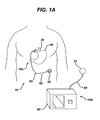
- FIG. 1A is a schematic diagram of one embodiment of a food intake restriction system
- FIG. 1B is perspective view of an implantable portion of the food intake restriction system of FIG. 1A ;
- FIG. 2A is a perspective view of a restriction device of the restriction system of FIG. 1A ;
- FIG. 2B is a perspective view of the restriction device of FIG. 2A applied about the gastro-esophageal junction of a stomach;
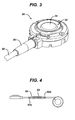
- FIG. 3 is a perspective view of an injection port housing of FIG. 1A ;
- FIG. 4 is a perspective view of the implantable portion of the food intake restriction system of FIG. 1A showing a cross-sectional view of an antenna housing;
- FIG. 5 is a perspective, partially transparent view of the antenna housing of FIG. 4 ;
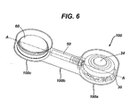
- FIG. 6 is a perspective view of one embodiment of a constraining element disposed around at least a portion of the injection port housing and antenna housing of FIGS. 1B and 4 ;
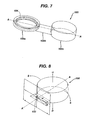
- FIG. 7 is a perspective view of the constraining element of FIG. 6 ;
- FIG. 8 is a perspective cross-sectional view of the constraining element of FIG. 6 showing a lumen extending therethrough.
- Various exemplary methods and devices are provided for limiting movement of an antenna housing associated with a restriction system to allow for alignment and communication with an external device.
- the antenna housing is constrained relative to another housing, such as an injection port 30, that is anchored to tissue.
- a constraining element can be coupled to the housings and it can limit or substantially prevent movement of the housings relative to one another, preferably in at least one plane of motion. Since housings tend to shift once implanted in tissue, the ability to control movement between the housings can be particularly advantageous to allow for effective wireless communication with an external device.
- FIG. 1 illustrates one exemplary embodiment of a food intake restriction system 10.
- the system 10 generally includes an implantable portion 10a having an adjustable gastric band 20 that is configured to be positioned around the upper portion of a patient's stomach 40, and an injection port 30 that is fluidly coupled to the adjustable gastric band 20, e.g., via a catheter 50.
- the injection port 30 is adapted to allow fluid to be introduced into and removed from the gastric band 20 to thereby adjust the size of the band, and thus the pressure applied to the stomach.
- the injection port 30 can thus be implanted at a location within the body that is accessible through the tissue.
- injection ports are positioned in the lateral subcostal region of the patient's abdomen under the skin and layers of fatty tissue. Surgeons also typically implant injection ports on the sternum of the patient.
- the implantable portion 10a can also include an antenna housing 60 configured to communicate wirelessly with an external device.
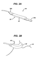
- FIG. 2A shows the gastric band 20 in more detail.
- the gastric band 20 can have a variety of configurations, and various gastric bands currently known in the art can be used with the present invention
- the gastric band 20 has a generally elongated shape with a support structure 22 having first and second opposite ends 20a, 20b that can be secured to each other.
- Various mating techniques can be used to secure the ends 20a, 20b to one another.
- the ends 20a, 20b are in the form of straps that mate together, with one laying on top of the other.
- the gastric band 20 can also include a variable volume member, such as an inflatable balloon 24, that is disposed or formed on one side of the support structure 22, and that is configured to be positioned adjacent to tissue.
- the balloon 24 can expand or contract against the outer wall of the stomach to form an adjustable stoma for controllably restricting food intake into the stomach.
- the gastric band can have a variety of other configurations, moreover the various methods and devices disclosed herein have equal applicability to other types of implantable bands.
- bands are used for the treatment of fecal incontinence, as described in U.S. Pat. No. 6,461,292 which is hereby incorporated herein by reference.
- Bands can also be used to treat urinary incontinence, as described in U.S. Patent Application 2003/0105385 which is hereby incorporated herein by reference.
- Bands can also be used to treat heartburn and/or acid reflux, as disclosed in U.S. Pat. No. 6,470,892 which is hereby incorporated herein by reference.
- Bands can also be used to treat impotence, as described in U.S. Patent Application 2003/0114729 which is hereby incorporated herein by reference.
- FIG. 2B shows the adjustable gastric band 20 applied about the gastro-esophageal junction of a patient.
- the band 20 at least substantially encloses the upper portion of the stomach 40 near the junction with the esophagus 42.
- the band 20 can be inflated, e.g., using saline, to decrease the size of the stoma opening.
- various techniques including mechanical and electrical techniques, can be used to adjust the band.
- the fluid injection port 30 can also have a variety of configurations.
- the injection port 30 has a generally cylindrical housing with a distal or bottom surface and a perimeter wall extending proximally from the bottom surface and defining a proximal opening 32.
- the proximal opening 32 can include a needle-penetrable septum 34 extending there across and providing access to a fluid reservoir (not shown in FIG. 3 ) formed within the housing.
- the septum is preferably placed in a proximal enough position such that the depth of the reservoir is sufficient enough to expose the open tip of a needle, such as a Huber needle, so that fluid transfer can take place.
- the septum 34 is preferably arranged so that it will self seal after being punctured by a needle and the needle is withdrawn.
- the port can further include a catheter tube connection member 36 that is in fluid communication with the reservoir and that is configured to couple to a catheter (e.g., the catheter 50).
- a catheter e.g., the catheter 50.
- the housing 30 can be made from any number of materials, including stainless steel, titanium, or polymeric materials, and the septum can likewise be made from any number of materials, including silicone.
- the port 30 can also be configured to be anchored to tissue.
- the port 30 can include one or more suture-receiving members adapted to receive a suture for anchoring the port 30 to tissue, and/or the port 30 can include one or more anchors or hooks adapted to be deployed into tissue.
- any technique can be used to anchor the port 30 in tissue.
- Various techniques for anchoring an injection port to tissue are disclosed in more detail in commonly-owned U.S. Publication No. 2007/0208313 entitled “Method of Implanting a Fluid Injection Port,” filed on May 7, 2007, and U.S. Publication No. 2007/0010790 entitled “Injection Port,” filed June 24, 2005, both of which are hereby incorporated by reference in their entireties.
- the system can also include an antenna housing 60 having an antenna 62 therein that is configured to communicate wirelessly with an external device to allow power and/or data to be transferred between the antenna and the external device.
- the antenna 62 can be, for example, a TET/telemetry coil for inductively coupling with a TET/telemetry coil in an external device (e.g., a device external to the patient's body).
- the antenna 62 can be coupled to various components disposed within the antenna housing 60 or elsewhere within the system 10.
- the antenna 62 can include or be coupled to a pressure measuring device that is in communication with the closed fluid circuit and that is configured to measure a fluid pressure that corresponds to the amount of restriction applied by the adjustable gastric band to the patient's stomach. Measuring the fluid pressure enables a physician to evaluate the restriction created by a band adjustment.
- the pressure measuring device can be in the form of a pressure sensor 63, which can be unitary with the antenna 62 or a separate component, that can be disposed within the housing 60.
- the pressure measuring device can, however, be disposed anywhere within the closed hydraulic circuit of the implantable portion, and various exemplary locations and configurations are disclosed in more detail in commonly-owned U.S. Publication No.
- the pressure sensing system can further include a temperature sensor (not shown).
- the sensing system can also be configured to measure a variety of other parameters, for example, pulse count and pulse width.
- the illustrated housing 60 includes an inlet 60a and an outlet 60b that are in fluid communication with the fluid in the system.
- the sensor can be disposed within the housing 60 and it can be configured to respond to fluid pressure changes within the hydraulic circuit and convert the pressure changes into a usable form of data. As shown in more detail in FIG.
- the pressure sensing system can also include a motherboard 64 that can serve as at least a portion of a hermetic container to prevent fluid from contacting any elements disposed within the housing 60, except as discussed for the sensor.
- the housing 60 can be made from any biocompatible material appropriate for use in a body, such as a polymer, silicone, ceramic, glass, biocompatible metal, and other similar types of material.
- the housing 60 can be made from any one or more of transparent (as shown in FIG. 5 ), opaque, semi-opaque, and radio-opaque materials.
- the motherboard 64 including, among other elements, a microcontroller 65 (e.g., a processor), can also be disposed within the housing 60 to help process and communicate pressure measurements gathered by the sensor, and also possibly other data related to the band 20.
- the motherboard 64 can also include a transcutaneous energy transfer (TET)/telemetry coil and a capacitor.
- TET transcutaneous energy transfer
- a temperature sensor can be integrated into the motherboard 64.
- the microcontroller 65, the TET/telemetry coil and/or antenna, the capacitor, and/or the temperature sensor can be in communication via the motherboard 64 or via any other suitable component(s).
- the TET/telemetry coil and/or antenna and capacitor can collectively form a tuned tank circuit for receiving power from the external portion 10b and transmitting pressure measurements to an external device, e.g., the reading device 70.
- the microcontroller and capacitor can be in communication via the motherboard or via any other suitable component(s).
- the antenna 62 disposed in the housing 60 can have a variety of configurations, but in the illustrated embodiment is in the form of a planar coil on the motherboard 64.
- the antenna 62 can be configured to emit field lines directed along an axis extending between superior and inferior surfaces of the housing 60. This can allow for optimal communication between the antenna 62 and an external device as it is preferable for the antenna 62 to be maintained in a position substantially parallel to a tissue surface.
- a wireless pressure sensor provided by CardioMEMS, Inc. of Atlanta, Georgia
- a suitable MEMS pressure sensor may be obtained from any other source, including but not limited to Integrated Sensing Systems (ISSYS), and Remon Medical.
- ISSYS Integrated Sensing Systems
- One exemplary MEMS pressure sensor is described in U.S. Patent No. 6,855,115 , the disclosure of which is incorporated by reference herein for illustrative purposes only.
- suitable pressure sensors may include, but are not limited to, capacitive, piezoresistive, silicon strain gauge, or ultrasonic (acoustic) pressure sensors, as well as various other devices capable of measuring pressure.
- the system can include a constraining element coupled between first and second housings and configured to limit movement between first and second housings.
- a constraining element coupled between first and second housings and configured to limit movement between first and second housings. This will allow the port 30, for example, to be anchored to tissue and the antenna housing 60 to be maintained in a substantially fixed orientation relative to the port 30. As a result, the antenna housing 60 can be maintained in a position substantially parallel to a tissue surface, thus allowing optimal communication between the antenna 62 and an external device.
- the constraining element can be in the form of a sheath 100 extending between and optionally disposed around at least a portion of the injection port 30 and the antenna housing 60.
- the sheath 100 can be constructed to limit movement, e.g., rotational/torsional movement, between the housings preferably about an axis extending therebetween. Movement can be completely prevented, or merely limited in one or more directions or planes of motion.
- the sheath 100 has a first portion 100a configured to fit around the injection port 30, a second portion 100b adapted to extend between the injection port 30 and the sensor housing 60, and a third portion 100c adapted to fit around the sensor housing 60, as will be discussed in more detail below.
- the sheath 100 can be formed from a variety of materials, and it can be rigid or flexible, but in the preferred embodiment the sheath 100 is at least semi-rigid to limit movement between the injection port 30 and the sensor housing 60.
- the sheath 100 can be formed from an elastomeric material.
- the sheath 100 can be formed from a hermetic or near-hermetic material as the sheath 100 can also be configured to form a seal around the injection port 30 and the sensor housing 60. This seal can be configured to substantially eliminate transport of materials both into and out of the sheath 100 in order to provide protection to the components housed within the sheath 100, including the components housed in the injection port 30 and the sensor housing 60.
- a hermetic seal can be achieved with a variety of hermetic materials, such as laser welded titanium.
- the sheath 100 can be formed from any material that has the ability to form a hermetic seal using any known technique for forming a seal, including AuSn brazing, anodic bonding, seam welding, or impulse welding.
- a near-hermetic seal can be achieved using a variety of near-hermetic materials to form the sheath 100, such as materials configured to slow the ingress of moisture through the sheath.
- a near-hermetic seal can also be achieved through the use of a coating formed around the sheath.
- a person skilled in the art will appreciate that a variety of materials can form a near-hermetic seal, including but not limited to silicones, metallized LCP, parylene-C, PDMS, and PEEK. Moreover, a person skilled in the art will appreciate that a variety of technologies can be used to form a coating around the sheath 100, including nanoreinforced moisture barrier coatings and self-aligned nano-particle engineered surfaces. In addition, the sheath 100 can also be formed from a keratin.
- keratin is less likely to react or be rejected by the body as it is a substance found in the body, it is less susceptible to humidity, it can be gamma sterilized, and can be injection molded to form the various components of the sheath 100. Keratin has also been shown to accelerate tissue healing as it can cooperate with the body's healing mechanisms.
- the sheath 100 can be formed from any material that can be implanted in the body and that can provide limitation of movement between the housings as described above.
- the first and third portions 100a, 100c of the sheath 100 can have any configuration that allows the sheath to fit around and/or mate to the injection port 30 and the antenna housing 60, and the sheath 100 can be formed in a variety of ways.
- the first portion 100a of the sheath 100 can be overmolded to encompass a portion of the injection port 30, but preferably not the entire injection port 30.
- at least the septum 34 extending across the injection port 30 will not be encompassed by the sheath 100 as the septum 34 is configured to provide access to the fluid reservoir formed within the housing of the injection port 30.
- the sheath 100 can, however, be needle-penetrable to allow fluid to be introduced into an injection port 30 fully encapsulated by the sheath 100.
- the first portion 100a of the sheath 100 is formed around an engagement flange 104 formed on or matable to the injection port 30.
- the third portion 100c of the sheath 100 can likewise be overmolded to encapsulate a portion of or preferably the entire housing 60.
- the sheath 100 is configured to provide enough of a seal to protect the components within the injection port 30 and the antenna housing 60 and provide enough stability to the injection port 30 and the housing 60 to limit movement therebetween.
- the sheath 100 need not include the first and third portions 100a, 100c, but rather can merely extend between the port 30 and the housing 60 without encapsulating the port 30 and the housing 60.
- the second portion 100b of the sheath 100 can also have a variety of configurations.
- the second portion 100b includes a lumen 102 extending therethrough that is configured to allow for fluid flow between the injection port 30 and the antenna housing 60.
- the lumen 102 can contain a catheter 50, as shown in FIG. 6 , extending therethrough to allow for fluid flow through the catheter 50 between the injection port 30 and the antenna housing 60. This can be achieved either by forming the sheath 100 around the catheter 50, or the catheter 50 can be routed through the lumen 102 extending through the sheath 100.
- the catheter 50 can have a variety of configurations, but is preferably sized and shaped to fit within the lumen 102 of the sheath 100.
- the catheter 50 can have a length that allows the catheter 50 to extend a distance between the injection port 30 to the antenna housing 60 such that the port 30 and the housing 60 are spaced a distance apart.
- the lumen 102 of the sheath 100 can be configured to allow fluid flow therethrough without the need for a catheter 50 within the lumen 102.
- the lumen 102 can have any size and shape that allows for fluid to flow between the injection port 30 and the sensor housing 60.
- the second portion 100b of the sheath 100 is also preferably adapted to limit movement between the port 30 and the housing 60. While various techniques can be used to limit movement, in an exemplary embodiment the second portion 100b can be configured to provide rigidity in any or all planes or axes of movement. In one exemplary embodiment, the second portion 100b of the sheath 100 is configured to limit movement about an axis A ( FIG. 6 ) extending between the port 30 and the housing 60 to prevent rotational movement between the injection port 30 and the housing 60. A person skilled in the art will appreciate that the rigidity and/or shape of the second portion 100b of the sheath 100 can be chosen to achieve a desired amount of constraint on movement.
- the rigidity and/or shape of the second portion 100b of the sheath 100 can be selected to allow the injection port 30 and the housing 60 to be easily introduced in the body, for example, by allowing bending motion into and out of a plane containing the sheath 100, the port 30, and the housing 60.
- the rigidity and/or shape of the sheath 100 can prevent torsional movement of the injection port 30 and the housing 60 about the axis A extending between the port 30 and the housing 60 to keep the antenna 62 within the antenna housing 60 in a specific orientation in relation to the port 30, and thus the skin surface.
- the rigidity and/or shape of the second portion 100b of the sheath 100 can also be selected to allow the catheter 50 to be easily routed through the lumen 102 formed in the sheath 100 in an embodiment described above in which the sheath 100 is not formed around the catheter and the catheter needs to be inserted through the lumen 102.
- the rotational stability provided by the sheath 100 can increase the ease with which the catheter is positioned within the lumen 102 in the sheath 100.
- the second portion 100b of the sheath 100 can have a shape that allows for bending between the port 30 and the housing 60 but prevents rotation therebetween.
- the second portion 100b of the sheath 100 has a generally elongate substantially flat configuration that limits or prevents rotational movement between the injection port 30 and the antenna housing 60 along the axis A of the second portion 100b of the sheath 100, but yet allows bending to occur along the axis A.
- the second portion 100b of the sheath 100 has a width w that is greater than a height h.
- the shortness of the height h is chosen to allow the port 30 and the housing 60 to bend in a first direction (i.e., in an out of a plane extending through the port 30 and the housing 60) while the wider width w prevents bending in a second direction that is substantially perpendicular to the first direction.
- the port 30 and the housing 60 can move up and down out of the plane in the direction U, D indicated in FIG. 8 , but are prevented from moving sideways within the plane in the direction S indicated in FIG. 8 , in addition to being prevented from rotating relative to one another along the axis. This results in the limitation of rotation about the axis A extending between the port 30 and the housing 60.
- the sheath 100 can act as a spring to prevent twisting about the axis A of the second portion 100b of the sheath 100 (i.e., the axis A extending between the housings).
- the sheath 100 can also have a flat distal surface that facilitates positioning of the sheath 100 on a tissue surface during and after implantation, and a convex proximal surface that can be curved to accommodate the lumen 102 extending through the second portion 100b of the sheath 100, while still maintaining a low profile.
- the second portion 100b of the sheath can also extend between the port 30 and the housing 60 between distal portions of the port 30 and the housing 60 to allow the flat distal surface of the sheath 100 to be co-planar with the distal surfaces of the port 30 and the housing 60, and thus the sheath 100, the port 30, and the housing 60 can rest on a tissue surface in one plane, for example, to ease implantation and anchoring the port 30 to tissue.
- the second portion 100b of the sheath 100 can have any configuration adapted to limit movement between the injection port 30 and the housing 60.
- the restriction system 10 shown in FIG. 1A can be implanted using techniques known in the art.
- the gastric band 20 can be introduced into the patient's body and positioned around the stomach to restrict the pathway into the stomach, thus limiting food intake.
- the housing 60 and the port 30 can be implanted in tissue, preferably in the fascia, and they can be coupled to the band 20 to allow fluid communication therebetween.
- the port 30 is anchored to a surface of the fascia, such that the port 30 is substantially parallel to the skin surface to allow access to the port 30.
- the antenna housing 60 which is spaced a distance apart from the port 30 and preferably positioned on the fascia, will be limited or prevented from moving due to the constraining member.
- the sheath 100 limits or prevents movement of the housing 60 containing the antenna 62 relative to the injection port 30, an external device placed on the skin surface above the housing 60 will be aligned with and can thus communicate with the antenna 62.
- the sheath 100 can prevent rotational movement between the port 30 and the housing 60 along an axis extending therebetween, while allowing for bending in a plane of motion substantially perpendicular to the axis extending between the port 30 and the housing 60. This prevention of rotational movement will allow the antenna 62 and the external device to be substantially parallel to one another as the sheath 100 prevents the antenna 62 from rotating away from the surface of the tissue.
- the devices disclosed herein can be designed to be disposed of after a single use, or they can be designed to be used multiple times. In either case, however, the device can be reconditioned for reuse after at least one use. Reconditioning can include any combination of the steps of disassembly of the device, followed by cleaning or replacement of particular pieces, and subsequent reassembly. In particular, the device can be disassembled, and any number of the particular pieces or parts of the device can be selectively replaced or removed in any combination. Upon cleaning and/or replacement of particular parts, the device can be reassembled for subsequent use either at a reconditioning facility, or by a surgical team immediately prior to a surgical procedure.
- reconditioning of a device can utilize a variety of techniques for disassembly, cleaning/replacement, and reassembly. Use of such techniques, and the resulting reconditioned device, are all within the scope of the present invention.
- the invention described herein will be processed before surgery.
- a new or used instrument is obtained and if necessary cleaned.
- the instrument can then be sterilized.
- the instrument is placed in a closed and sealed container, such as a plastic or TYVEK bag.
- the container and instrument are then placed in a field of radiation that can penetrate the container, such as gamma radiation, x-rays, or high-energy electrons.
- the radiation kills bacteria on the instrument and in the container.
- the sterilized instrument can then be stored in the sterile container.
- the sealed container keeps the instrument sterile until it is opened in the medical facility.
- device is sterilized. This can be done by any number of ways known to those skilled in the art including beta or gamma radiation, ethylene oxide, steam.
Landscapes
- Health & Medical Sciences (AREA)
- Engineering & Computer Science (AREA)
- Life Sciences & Earth Sciences (AREA)
- Animal Behavior & Ethology (AREA)
- Obesity (AREA)
- Nursing (AREA)
- Orthopedic Medicine & Surgery (AREA)
- Biomedical Technology (AREA)
- Heart & Thoracic Surgery (AREA)
- Vascular Medicine (AREA)
- Veterinary Medicine (AREA)
- Child & Adolescent Psychology (AREA)
- General Health & Medical Sciences (AREA)
- Public Health (AREA)
- Computer Networks & Wireless Communication (AREA)
- Surgical Instruments (AREA)
- Measuring Fluid Pressure (AREA)
- Measuring And Recording Apparatus For Diagnosis (AREA)
- Details Of Aerials (AREA)
- Aerials With Secondary Devices (AREA)
Abstract
Description
- The present application relates to methods and devices for fixing antenna orientation in a restriction system.
- Obesity is a growing global concern, as the number of individuals classified as overweight, obese, or morbidly obese continues to increase every year. Obesity is associated with several co-morbidities, including hypertension, type II diabetes, and sleep apnea. Morbid obesity, defined as when a person is 100 pounds or more over ideal body weight or having a body mass index (BMI) of 40 or greater, poses the greatest risks for severe health problems. Accordingly, a great deal of attention is being focused on treating patients with this condition. One method of treating morbid obesity is the placement of a restriction device, such as an elongated band, around the upper portion of the stomach. Gastric bands are typically comprised of a fluid-filled elastomeric balloon with fixed endpoints that encircles the stomach just inferior to the esophageal-gastric junction. This forms a small gastric pouch above the band and a reduced stoma opening inferior to the gastro-esophageal junction. When fluid is infused into the balloon, the band expands against the stomach creating further food intake restriction or a smaller stoma opening in the stomach. To decrease this restriction level, fluid is removed from the band. The effect of the band is to reduce the available stomach volume and thus the amount of food that can be consumed before becoming "full."
- Food restriction devices have also comprised mechanically adjusted bands that similarly encircle the upper portion of the stomach. These bands include any number of resilient materials or gearing devices, as well as drive members, for adjusting the bands. Additionally, gastric bands have been developed that include both hydraulic and mechanical drive elements. An example of such an adjustable gastric band is disclosed in
U.S. Pat. No. 6,067,991 , entitled "Mechanical Food Intake Restriction Device" which issued on May 30, 2000, and is incorporated herein by reference. Another method for limiting the available food volume in the stomach cavity is implanting an inflatable elastomeric balloon within the stomach cavity itself. - The balloon is filled with a fluid to expand against the stomach walls and, thereby, decrease the available food volume within the stomach.
- With each of the above-described food limitation devices, safe, effective treatment requires that the device be regularly monitored and adjusted to vary the degree of affect on food intake. With banding devices, the gastric pouch above the band may substantially increase in size following the initial implantation. Accordingly, the stoma opening in the stomach must initially be made large enough to enable the patient to receive adequate nutrition while the stomach adapts to the banding device. As the patient's body adapts to the implant, the band may be adjusted to vary the stoma size. In addition, it is desirable to vary the stoma size in order to accommodate changes in the patient's body or treatment regime, or in a more urgent case, to relieve an obstruction or severe esophageal dysmotility or dilatation. Traditionally, adjusting a hydraulic gastric band required a scheduled clinician visit during which a Huber (non-coring) needle and syringe were used to penetrate the patient's skin and add or remove fluid from the balloon. More recently, devices have been developed which enable non-invasive adjustments of the band. An external programmer communicates with the implant using telemetry to control the stoma diameter of the band. During a scheduled visit, a physician places a hand-held portion of the programmer near the implant and transmits power and command signals to the implant. The implant in turn adjusts the stoma diameter of the band and transmits a response command to the programmer.
- One problem that can arise is giving stability to various housings in a restriction system, such as an antenna housing for communicating with an external device. Specifically, it can be difficult to provide orientational stability to an antenna housing once it is implanted as the tissue underneath the skin does not provide a flat surface for mounting and the housing may shift locations as the patient loses or gains weight, or even during movement by the patient. As a result, it can be difficult to align an external device with the antenna housing to enable wireless communication.
- Accordingly, there remains a need for improved methods and devices for substantially fixing the orientation of an antenna housing implanted in tissue.
- Various methods and devices are provided for substantially fixing the orientation of a housing, such as an antenna housing, within tissue. In one embodiment, a restriction system is provided having a first housing with a reservoir formed therein for receiving fluid. The first housing can be configured to be anchored to tissue. The system can also include a second housing spaced apart from and in fluid communication with the first housing. The second housing can have an antenna therein configured to wirelessly communicate with an external device. The system can also include a restriction device in fluid communication with the first and second housings and adapted to form a restriction in a pathway, and a constraining element coupled to the first and second housings and configured to limit rotational movement of the first and second housings relative to one another. In an exemplary embodiment, the constraining element is configured to substantially prevent rotation of the first and second housings along an axis extending between the first and second housings.
- The constraining element can have various configurations. In one embodiment, the constraining element can be substantially rigid in a first plane of motion and flexible in a second plane of motion that differs from the first plane of motion. For example, the constraining element can be a sheath disposed around at least a portion of the first and second housings. In one embodiment, the sheath can be sealed with a hermetic coating. The system can also include a connector, such as a catheter, extending through the constraining element between the first and second housings. The connector can be configured to allow fluid flow therethrough between the first and second housings. Alternatively, the constraining element can include a lumen extending therethrough and configured to allow fluid flow between the first and second housings. The constraining element can also include other features, such as an outer layer formed from a compliant material, such as keratin and silicone.
- In another embodiment, a restriction system is provided having a fill port with a needle-penetrable septum and a reservoir formed therein and configured to receive fluid. An antenna housing can be coupled to the fill port and it can have an antenna therein configured to wirelessly communicate with an external device. The system can also include a constraining element extending between the fill port and the antenna housing. The constraining element can be substantially rigid in a first plane of motion and flexible in a second plane of motion that differs from the first plane of motion. For example, the constraining element can prevent rotation between the antenna housing and the fill port. The constraining element can have various configurations, as discussed above.
- Exemplary methods are also provided for constraining movement of a housing in tissue, and in one embodiment the method can include implanting a first housing in tissue. The first housing can have a second housing spaced apart from but coupled thereto. A constraining element coupled between the first and second housings can substantially prevent rotational movement of the second housing relative to the first housing about an axis extending therebetween such that the second housing is maintained in a substantially fixed orientation in the tissue. The method can also include positioning an external device above a tissue surface, and activating the external device to communicate with an antenna disposed within the second housing. In one embodiment, implanting the first housing in tissue can include anchoring the first housing to tissue. The first housing can contain fluid therein and the constraining element can include a lumen extending therethrough such that the fluid can flow between the first and second housings. The fluid can also flow through a catheter extending through the lumen in the constraining element. The method can also include implanting a restriction device coupled to at least one of the first and second housings. The restriction device can form a restriction in a pathway. In a further embodiment, the second housing can include a sensor that measures the pressure of fluid in the restriction device.
- The following is a non-exhaustive list of embodiments of the invention that may be claimed in this application or in subsequently filed divisional applications:
- 1. A restriction system, comprising:
- a first housing having a reservoir formed therein for receiving fluid, the first housing being configured to be anchored to tissue;
- a second housing spaced apart from and in fluid communication with the first housing, the second housing having an antenna therein configured to wirelessly communicate with an external device;
- a restriction device in fluid communication with the first and second housings and adapted to form a restriction in a pathway; and
- a constraining element coupled to the first and second housings and configured to limit rotational movement of the first and second housings relative to one another.
- 2. The system of embodiment 1, wherein the constraining element is configured to substantially prevent rotation of the first and second housings along an axis extending between the first and second housings.
- 3. The system of embodiment 1, wherein the constraining element is substantially rigid in a first plane of motion and flexible in a second plane of motion that differs from the first plane of motion.
- 4. The system of embodiment 1, wherein the constraining element comprises a sheath disposed around at least a portion of the first and second housings.
- 5. The system of embodiment 4, wherein the sheath is sealed with a hermetic coating.
- 6. The system of embodiment 1, further comprising a connector extending through the constraining element between the first and second housings, the connector configured to allow fluid flow therethrough between the first and second housings.
- 7. The system of embodiment 1, wherein the constraining element includes a lumen extending therethrough and configured to allow fluid flow between the first and second housings.
- 8. The system of embodiment 1, wherein the constraining element includes an outer layer formed from a compliant material.
- 9. The system of
embodiment 8, wherein the compliant material is selected from the group consisting of keratin and silicone. - 10. A restriction system, comprising:
- a fill port having a needle-penetrable septum and a reservoir formed therein and configured to receive fluid;
- an antenna housing coupled to the fill port and having an antenna therein configured to wirelessly communicate with an external device; and
- a constraining element extending between the fill port and the antenna housing, the constraining element being substantially rigid in a first plane of motion and flexible in a second plane of motion that differs from the first plane of motion.
- 11. The system of
embodiment 10, wherein the constraining element prevents rotation between the antenna housing and the fill port. - 12. The system of
embodiment 10, wherein the constraining element comprises a sheath formed over at least a portion of the fill port and the antenna housing. - 13. The system of
embodiment 10, further comprising a catheter extending through the constraining element and configured to allow fluid flow between the fill port and the sensor housing. - 14. The system of
embodiment 10, wherein the constraining element includes a lumen formed therethrough and configured to allow fluid flow between the fill port and the sensor housing. - 15. A method for constraining movement of a housing in tissue, comprising:
- implanting a first housing in tissue, the first housing having a second housing spaced apart from but coupled thereto, wherein a constraining element coupled between the first and second housings substantially prevents rotational movement of the second housing relative to the first housing about an axis extending therebetween such that the second housing is maintained in a substantially fixed orientation in the tissue.
- 16. The method of embodiment 15, further comprising positioning an external device above a tissue surface, and activating the external device to communicate with an antenna disposed within the second housing.
- 17. The method of embodiment 15, wherein implanting the first housing in tissue comprises anchoring the first housing to tissue.
- 18. The method of embodiment Error! Reference source not found., wherein the first housing contains fluid therein and the constraining element includes a lumen extending therethrough such that the fluid can flow between the first and second housings.
- 19. The method of embodiment Error! Reference source not found., wherein the fluid flows through a catheter extending through the lumen in the constraining element.
- 20. The method of embodiment 15, further comprising implanting a restriction device coupled to at least one of the first and second housings, the restriction device forming a restriction in a pathway.
- 21. The method of embodiment Error! Reference source not found., wherein the second housing includes a sensor that measures a fluid pressure of fluid in the restriction device.
- The invention will be more fully understood from the following detailed description taken in conjunction with the accompanying drawings, in which:
-
FIG. 1A is a schematic diagram of one embodiment of a food intake restriction system; -
FIG. 1B is perspective view of an implantable portion of the food intake restriction system ofFIG. 1A ; -
FIG. 2A is a perspective view of a restriction device of the restriction system ofFIG. 1A ; -
FIG. 2B is a perspective view of the restriction device ofFIG. 2A applied about the gastro-esophageal junction of a stomach; -
FIG. 3 is a perspective view of an injection port housing ofFIG. 1A ; -
FIG. 4 is a perspective view of the implantable portion of the food intake restriction system ofFIG. 1A showing a cross-sectional view of an antenna housing; -
FIG. 5 is a perspective, partially transparent view of the antenna housing ofFIG. 4 ; -
FIG. 6 is a perspective view of one embodiment of a constraining element disposed around at least a portion of the injection port housing and antenna housing ofFIGS. 1B and4 ; -
FIG. 7 is a perspective view of the constraining element ofFIG. 6 ; and -
FIG. 8 is a perspective cross-sectional view of the constraining element ofFIG. 6 showing a lumen extending therethrough. - Certain exemplary embodiments will now be described to provide an overall understanding of the principles of the structure, function, manufacture, and use of the devices and methods disclosed herein. One or more examples of these embodiments are illustrated in the accompanying drawings. Those skilled in the art will understand that the devices and methods specifically described herein and illustrated in the accompanying drawings are non-limiting exemplary embodiments and that the scope of the present invention is defined solely by the claims. The features illustrated or described in connection with one exemplary embodiment may be combined with the features of other embodiments. Such modifications and variations are intended to be included within the scope of the present invention.
- Various exemplary methods and devices are provided for limiting movement of an antenna housing associated with a restriction system to allow for alignment and communication with an external device. In certain exemplary embodiments, the antenna housing is constrained relative to another housing, such as an
injection port 30, that is anchored to tissue. In particular, a constraining element can be coupled to the housings and it can limit or substantially prevent movement of the housings relative to one another, preferably in at least one plane of motion. Since housings tend to shift once implanted in tissue, the ability to control movement between the housings can be particularly advantageous to allow for effective wireless communication with an external device. - While the present invention can be used with a variety of restriction systems known in the art,
FIG. 1 illustrates one exemplary embodiment of a foodintake restriction system 10. As shown, thesystem 10 generally includes animplantable portion 10a having an adjustablegastric band 20 that is configured to be positioned around the upper portion of a patient'sstomach 40, and aninjection port 30 that is fluidly coupled to the adjustablegastric band 20, e.g., via acatheter 50. Theinjection port 30 is adapted to allow fluid to be introduced into and removed from thegastric band 20 to thereby adjust the size of the band, and thus the pressure applied to the stomach. Theinjection port 30 can thus be implanted at a location within the body that is accessible through the tissue. Typically, injection ports are positioned in the lateral subcostal region of the patient's abdomen under the skin and layers of fatty tissue. Surgeons also typically implant injection ports on the sternum of the patient. Theimplantable portion 10a can also include anantenna housing 60 configured to communicate wirelessly with an external device. -
FIG. 2A shows thegastric band 20 in more detail. While thegastric band 20 can have a variety of configurations, and various gastric bands currently known in the art can be used with the present invention, in the illustrated embodiment thegastric band 20 has a generally elongated shape with asupport structure 22 having first and second opposite ends 20a, 20b that can be secured to each other. Various mating techniques can be used to secure theends ends gastric band 20 can also include a variable volume member, such as aninflatable balloon 24, that is disposed or formed on one side of thesupport structure 22, and that is configured to be positioned adjacent to tissue. Theballoon 24 can expand or contract against the outer wall of the stomach to form an adjustable stoma for controllably restricting food intake into the stomach. A person skilled in the art will appreciate that the gastric band can have a variety of other configurations, moreover the various methods and devices disclosed herein have equal applicability to other types of implantable bands. For example, bands are used for the treatment of fecal incontinence, as described inU.S. Pat. No. 6,461,292 which is hereby incorporated herein by reference. Bands can also be used to treat urinary incontinence, as described inU.S. Patent Application 2003/0105385 which is hereby incorporated herein by reference. Bands can also be used to treat heartburn and/or acid reflux, as disclosed inU.S. Pat. No. 6,470,892 which is hereby incorporated herein by reference. Bands can also be used to treat impotence, as described inU.S. Patent Application 2003/0114729 which is hereby incorporated herein by reference. -
FIG. 2B shows the adjustablegastric band 20 applied about the gastro-esophageal junction of a patient. As shown, theband 20 at least substantially encloses the upper portion of thestomach 40 near the junction with theesophagus 42. After theband 20 is implanted, preferably in the deflated configuration wherein theband 20 contains little or no fluid, theband 20 can be inflated, e.g., using saline, to decrease the size of the stoma opening. A person skilled in the art will appreciate that various techniques, including mechanical and electrical techniques, can be used to adjust the band. - The
fluid injection port 30 can also have a variety of configurations. In the embodiment shown inFIG. 3 , theinjection port 30 has a generally cylindrical housing with a distal or bottom surface and a perimeter wall extending proximally from the bottom surface and defining aproximal opening 32. Theproximal opening 32 can include a needle-penetrable septum 34 extending there across and providing access to a fluid reservoir (not shown inFIG. 3 ) formed within the housing. The septum is preferably placed in a proximal enough position such that the depth of the reservoir is sufficient enough to expose the open tip of a needle, such as a Huber needle, so that fluid transfer can take place. Theseptum 34 is preferably arranged so that it will self seal after being punctured by a needle and the needle is withdrawn. As further shown inFIG. 3 , the port can further include a cathetertube connection member 36 that is in fluid communication with the reservoir and that is configured to couple to a catheter (e.g., the catheter 50). A person skilled in the art will appreciate that thehousing 30 can be made from any number of materials, including stainless steel, titanium, or polymeric materials, and the septum can likewise be made from any number of materials, including silicone. Theport 30 can also be configured to be anchored to tissue. For example, theport 30 can include one or more suture-receiving members adapted to receive a suture for anchoring theport 30 to tissue, and/or theport 30 can include one or more anchors or hooks adapted to be deployed into tissue. A person skilled in the art will appreciate that any technique can be used to anchor theport 30 in tissue. Various techniques for anchoring an injection port to tissue are disclosed in more detail in commonly-ownedU.S. Publication No. 2007/0208313 entitled "Method of Implanting a Fluid Injection Port," filed on May 7, 2007, andU.S. Publication No. 2007/0010790 entitled "Injection Port," filed June 24, 2005, both of which are hereby incorporated by reference in their entireties. - As indicated above and as shown in
FIG. 4 , the system can also include anantenna housing 60 having anantenna 62 therein that is configured to communicate wirelessly with an external device to allow power and/or data to be transferred between the antenna and the external device. Theantenna 62 can be, for example, a TET/telemetry coil for inductively coupling with a TET/telemetry coil in an external device (e.g., a device external to the patient's body). Theantenna 62 can be coupled to various components disposed within theantenna housing 60 or elsewhere within thesystem 10. For example, in one embodiment theantenna 62 can include or be coupled to a pressure measuring device that is in communication with the closed fluid circuit and that is configured to measure a fluid pressure that corresponds to the amount of restriction applied by the adjustable gastric band to the patient's stomach. Measuring the fluid pressure enables a physician to evaluate the restriction created by a band adjustment. In an exemplary embodiment, the pressure measuring device can be in the form of apressure sensor 63, which can be unitary with theantenna 62 or a separate component, that can be disposed within thehousing 60. The pressure measuring device can, however, be disposed anywhere within the closed hydraulic circuit of the implantable portion, and various exemplary locations and configurations are disclosed in more detail in commonly-ownedU.S. Publication No. 2006/0211913 entitled "Non-Invasive Pressure Measurement In a Fluid Adjustable Restrictive Device, filed on March 7, 2006, which is hereby incorporated by reference in its entirety. Optionally, the pressure sensing system can further include a temperature sensor (not shown). The sensing system can also be configured to measure a variety of other parameters, for example, pulse count and pulse width. In general, as shown inFIG. 4 , the illustratedhousing 60 includes aninlet 60a and anoutlet 60b that are in fluid communication with the fluid in the system. The sensor can be disposed within thehousing 60 and it can be configured to respond to fluid pressure changes within the hydraulic circuit and convert the pressure changes into a usable form of data. As shown in more detail inFIG. 5 , the pressure sensing system can also include amotherboard 64 that can serve as at least a portion of a hermetic container to prevent fluid from contacting any elements disposed within thehousing 60, except as discussed for the sensor. Thehousing 60 can be made from any biocompatible material appropriate for use in a body, such as a polymer, silicone, ceramic, glass, biocompatible metal, and other similar types of material. Furthermore, thehousing 60 can be made from any one or more of transparent (as shown inFIG. 5 ), opaque, semi-opaque, and radio-opaque materials. Themotherboard 64 including, among other elements, a microcontroller 65 (e.g., a processor), can also be disposed within thehousing 60 to help process and communicate pressure measurements gathered by the sensor, and also possibly other data related to theband 20. As further discussed below, themotherboard 64 can also include a transcutaneous energy transfer (TET)/telemetry coil and a capacitor. Optionally, a temperature sensor can be integrated into themotherboard 64. Themicrocontroller 65, the TET/telemetry coil and/or antenna, the capacitor, and/or the temperature sensor can be in communication via themotherboard 64 or via any other suitable component(s). As indicated above, the TET/telemetry coil and/or antenna and capacitor can collectively form a tuned tank circuit for receiving power from theexternal portion 10b and transmitting pressure measurements to an external device, e.g., thereading device 70. The microcontroller and capacitor can be in communication via the motherboard or via any other suitable component(s). Theantenna 62 disposed in thehousing 60 can have a variety of configurations, but in the illustrated embodiment is in the form of a planar coil on themotherboard 64. Theantenna 62 can be configured to emit field lines directed along an axis extending between superior and inferior surfaces of thehousing 60. This can allow for optimal communication between theantenna 62 and an external device as it is preferable for theantenna 62 to be maintained in a position substantially parallel to a tissue surface. - Various pressure sensors known in the art can be used, such as a wireless pressure sensor provided by CardioMEMS, Inc. of Atlanta, Georgia, though a suitable MEMS pressure sensor may be obtained from any other source, including but not limited to Integrated Sensing Systems (ISSYS), and Remon Medical. One exemplary MEMS pressure sensor is described in
U.S. Patent No. 6,855,115 , the disclosure of which is incorporated by reference herein for illustrative purposes only. It will also be appreciated that suitable pressure sensors may include, but are not limited to, capacitive, piezoresistive, silicon strain gauge, or ultrasonic (acoustic) pressure sensors, as well as various other devices capable of measuring pressure. - As discussed above, the system can include a constraining element coupled between first and second housings and configured to limit movement between first and second housings. This will allow the
port 30, for example, to be anchored to tissue and theantenna housing 60 to be maintained in a substantially fixed orientation relative to theport 30. As a result, theantenna housing 60 can be maintained in a position substantially parallel to a tissue surface, thus allowing optimal communication between theantenna 62 and an external device. In an exemplary embodiment, the constraining element can be in the form of asheath 100 extending between and optionally disposed around at least a portion of theinjection port 30 and theantenna housing 60. Thesheath 100 can be constructed to limit movement, e.g., rotational/torsional movement, between the housings preferably about an axis extending therebetween. Movement can be completely prevented, or merely limited in one or more directions or planes of motion. In an exemplary embodiment, as shown inFIG. 6 , thesheath 100 has afirst portion 100a configured to fit around theinjection port 30, asecond portion 100b adapted to extend between theinjection port 30 and thesensor housing 60, and athird portion 100c adapted to fit around thesensor housing 60, as will be discussed in more detail below. - The
sheath 100 can be formed from a variety of materials, and it can be rigid or flexible, but in the preferred embodiment thesheath 100 is at least semi-rigid to limit movement between theinjection port 30 and thesensor housing 60. For example, thesheath 100 can be formed from an elastomeric material. In addition, thesheath 100 can be formed from a hermetic or near-hermetic material as thesheath 100 can also be configured to form a seal around theinjection port 30 and thesensor housing 60. This seal can be configured to substantially eliminate transport of materials both into and out of thesheath 100 in order to provide protection to the components housed within thesheath 100, including the components housed in theinjection port 30 and thesensor housing 60. A hermetic seal can be achieved with a variety of hermetic materials, such as laser welded titanium. A person skilled in the art will appreciate that thesheath 100 can be formed from any material that has the ability to form a hermetic seal using any known technique for forming a seal, including AuSn brazing, anodic bonding, seam welding, or impulse welding. A near-hermetic seal can be achieved using a variety of near-hermetic materials to form thesheath 100, such as materials configured to slow the ingress of moisture through the sheath. A near-hermetic seal can also be achieved through the use of a coating formed around the sheath. A person skilled in the art will appreciate that a variety of materials can form a near-hermetic seal, including but not limited to silicones, metallized LCP, parylene-C, PDMS, and PEEK. Moreover, a person skilled in the art will appreciate that a variety of technologies can be used to form a coating around thesheath 100, including nanoreinforced moisture barrier coatings and self-aligned nano-particle engineered surfaces. In addition, thesheath 100 can also be formed from a keratin. This can be advantageous as keratin is less likely to react or be rejected by the body as it is a substance found in the body, it is less susceptible to humidity, it can be gamma sterilized, and can be injection molded to form the various components of thesheath 100. Keratin has also been shown to accelerate tissue healing as it can cooperate with the body's healing mechanisms. A person skilled in the art will appreciate, however, that thesheath 100 can be formed from any material that can be implanted in the body and that can provide limitation of movement between the housings as described above. - As discussed above, the first and
third portions sheath 100 can have any configuration that allows the sheath to fit around and/or mate to theinjection port 30 and theantenna housing 60, and thesheath 100 can be formed in a variety of ways. For example, thefirst portion 100a of thesheath 100 can be overmolded to encompass a portion of theinjection port 30, but preferably not theentire injection port 30. Specifically, at least theseptum 34 extending across theinjection port 30 will not be encompassed by thesheath 100 as theseptum 34 is configured to provide access to the fluid reservoir formed within the housing of theinjection port 30. Thesheath 100 can, however, be needle-penetrable to allow fluid to be introduced into aninjection port 30 fully encapsulated by thesheath 100. In an exemplary embodiment illustrated inFIG. 7 , thefirst portion 100a of thesheath 100 is formed around anengagement flange 104 formed on or matable to theinjection port 30. Thethird portion 100c of thesheath 100 can likewise be overmolded to encapsulate a portion of or preferably theentire housing 60. A person skilled in the art will appreciate that as much or as little of theinjection port 30 and/or thehousing 60 can be encapsulated by thesheath 100, but preferably thesheath 100 is configured to provide enough of a seal to protect the components within theinjection port 30 and theantenna housing 60 and provide enough stability to theinjection port 30 and thehousing 60 to limit movement therebetween. In other embodiments, thesheath 100 need not include the first andthird portions port 30 and thehousing 60 without encapsulating theport 30 and thehousing 60. - The
second portion 100b of thesheath 100 can also have a variety of configurations. In an exemplary embodiment, thesecond portion 100b includes alumen 102 extending therethrough that is configured to allow for fluid flow between theinjection port 30 and theantenna housing 60. In one exemplary embodiment, thelumen 102 can contain acatheter 50, as shown inFIG. 6 , extending therethrough to allow for fluid flow through thecatheter 50 between theinjection port 30 and theantenna housing 60. This can be achieved either by forming thesheath 100 around thecatheter 50, or thecatheter 50 can be routed through thelumen 102 extending through thesheath 100. Thecatheter 50 can have a variety of configurations, but is preferably sized and shaped to fit within thelumen 102 of thesheath 100. Thecatheter 50 can have a length that allows thecatheter 50 to extend a distance between theinjection port 30 to theantenna housing 60 such that theport 30 and thehousing 60 are spaced a distance apart. In another exemplary embodiment, thelumen 102 of thesheath 100 can be configured to allow fluid flow therethrough without the need for acatheter 50 within thelumen 102. Thelumen 102 can have any size and shape that allows for fluid to flow between theinjection port 30 and thesensor housing 60. - As previously indicated, the
second portion 100b of thesheath 100 is also preferably adapted to limit movement between theport 30 and thehousing 60. While various techniques can be used to limit movement, in an exemplary embodiment thesecond portion 100b can be configured to provide rigidity in any or all planes or axes of movement. In one exemplary embodiment, thesecond portion 100b of thesheath 100 is configured to limit movement about an axis A (FIG. 6 ) extending between theport 30 and thehousing 60 to prevent rotational movement between theinjection port 30 and thehousing 60. A person skilled in the art will appreciate that the rigidity and/or shape of thesecond portion 100b of thesheath 100 can be chosen to achieve a desired amount of constraint on movement. For example, the rigidity and/or shape of thesecond portion 100b of thesheath 100 can be selected to allow theinjection port 30 and thehousing 60 to be easily introduced in the body, for example, by allowing bending motion into and out of a plane containing thesheath 100, theport 30, and thehousing 60. However, the rigidity and/or shape of thesheath 100 can prevent torsional movement of theinjection port 30 and thehousing 60 about the axis A extending between theport 30 and thehousing 60 to keep theantenna 62 within theantenna housing 60 in a specific orientation in relation to theport 30, and thus the skin surface. This can be advantageous as it allows for implantation of theantenna 62 in a specific and known position and orientation in relation to theport 30 and thus the skin surface to increase the ease with which theantenna 62 can communicate with an external device positioned adjacent the skin surface. In addition, the rigidity and/or shape of thesecond portion 100b of thesheath 100 can also be selected to allow thecatheter 50 to be easily routed through thelumen 102 formed in thesheath 100 in an embodiment described above in which thesheath 100 is not formed around the catheter and the catheter needs to be inserted through thelumen 102. For example, if theinjection port 30 is not placed in the same plane as theantenna housing 60, the rotational stability provided by thesheath 100 can increase the ease with which the catheter is positioned within thelumen 102 in thesheath 100. - In an exemplary embodiment, as shown, the
second portion 100b of thesheath 100 can have a shape that allows for bending between theport 30 and thehousing 60 but prevents rotation therebetween. As best shown inFIG. 8 , thesecond portion 100b of thesheath 100 has a generally elongate substantially flat configuration that limits or prevents rotational movement between theinjection port 30 and theantenna housing 60 along the axis A of thesecond portion 100b of thesheath 100, but yet allows bending to occur along the axis A. In particular, thesecond portion 100b of thesheath 100 has a width w that is greater than a height h. The shortness of the height h is chosen to allow theport 30 and thehousing 60 to bend in a first direction (i.e., in an out of a plane extending through theport 30 and the housing 60) while the wider width w prevents bending in a second direction that is substantially perpendicular to the first direction. In other words, theport 30 and thehousing 60 can move up and down out of the plane in the direction U, D indicated inFIG. 8 , but are prevented from moving sideways within the plane in the direction S indicated inFIG. 8 , in addition to being prevented from rotating relative to one another along the axis. This results in the limitation of rotation about the axis A extending between theport 30 and thehousing 60. In other words, thesheath 100 can act as a spring to prevent twisting about the axis A of thesecond portion 100b of the sheath 100 (i.e., the axis A extending between the housings). Thesheath 100 can also have a flat distal surface that facilitates positioning of thesheath 100 on a tissue surface during and after implantation, and a convex proximal surface that can be curved to accommodate thelumen 102 extending through thesecond portion 100b of thesheath 100, while still maintaining a low profile. Thesecond portion 100b of the sheath can also extend between theport 30 and thehousing 60 between distal portions of theport 30 and thehousing 60 to allow the flat distal surface of thesheath 100 to be co-planar with the distal surfaces of theport 30 and thehousing 60, and thus thesheath 100, theport 30, and thehousing 60 can rest on a tissue surface in one plane, for example, to ease implantation and anchoring theport 30 to tissue. A person skilled in the art will appreciate, however, that thesecond portion 100b of thesheath 100 can have any configuration adapted to limit movement between theinjection port 30 and thehousing 60. - In use, the
restriction system 10 shown inFIG. 1A can be implanted using techniques known in the art. For example, thegastric band 20 can be introduced into the patient's body and positioned around the stomach to restrict the pathway into the stomach, thus limiting food intake. Thehousing 60 and theport 30 can be implanted in tissue, preferably in the fascia, and they can be coupled to theband 20 to allow fluid communication therebetween. Preferably, theport 30 is anchored to a surface of the fascia, such that theport 30 is substantially parallel to the skin surface to allow access to theport 30. As a result of the position of theport 30, theantenna housing 60, which is spaced a distance apart from theport 30 and preferably positioned on the fascia, will be limited or prevented from moving due to the constraining member. - After implantation, it is necessary to be able to communicate with the restriction system, for example, to transmit power to the restriction system and/or communicate data to and from the restriction system. Since the
sheath 100 limits or prevents movement of thehousing 60 containing theantenna 62 relative to theinjection port 30, an external device placed on the skin surface above thehousing 60 will be aligned with and can thus communicate with theantenna 62. For example, thesheath 100 can prevent rotational movement between theport 30 and thehousing 60 along an axis extending therebetween, while allowing for bending in a plane of motion substantially perpendicular to the axis extending between theport 30 and thehousing 60. This prevention of rotational movement will allow theantenna 62 and the external device to be substantially parallel to one another as thesheath 100 prevents theantenna 62 from rotating away from the surface of the tissue. - The devices disclosed herein can be designed to be disposed of after a single use, or they can be designed to be used multiple times. In either case, however, the device can be reconditioned for reuse after at least one use. Reconditioning can include any combination of the steps of disassembly of the device, followed by cleaning or replacement of particular pieces, and subsequent reassembly. In particular, the device can be disassembled, and any number of the particular pieces or parts of the device can be selectively replaced or removed in any combination. Upon cleaning and/or replacement of particular parts, the device can be reassembled for subsequent use either at a reconditioning facility, or by a surgical team immediately prior to a surgical procedure. Those skilled in the art will appreciate that reconditioning of a device can utilize a variety of techniques for disassembly, cleaning/replacement, and reassembly. Use of such techniques, and the resulting reconditioned device, are all within the scope of the present invention.
- Preferably, the invention described herein will be processed before surgery. First, a new or used instrument is obtained and if necessary cleaned. The instrument can then be sterilized. In one sterilization technique, the instrument is placed in a closed and sealed container, such as a plastic or TYVEK bag. The container and instrument are then placed in a field of radiation that can penetrate the container, such as gamma radiation, x-rays, or high-energy electrons. The radiation kills bacteria on the instrument and in the container. The sterilized instrument can then be stored in the sterile container. The sealed container keeps the instrument sterile until it is opened in the medical facility.
- It is preferred that device is sterilized. This can be done by any number of ways known to those skilled in the art including beta or gamma radiation, ethylene oxide, steam.
- One of ordinary skill in the art will appreciate further features and advantages of the invention based on the above-described embodiments. Accordingly, the invention is not to be limited by what has been particularly shown and described, except as indicated by the appended claims. All publications and references cited herein are expressly incorporated herein by reference in their entirety.
Claims (15)
- A restriction system, comprising:a first housing having a reservoir formed therein for receiving fluid, the first housing being configured to be anchored to tissue;a second housing spaced apart from and in fluid communication with the first housing, the second housing having an antenna therein configured to wirelessly communicate with an external device;a restriction device in fluid communication with the first and second housings and adapted to form a restriction in a pathway; anda constraining element coupled to the first and second housings and configured to limit rotational movement of the first and second housings relative to one another.
- The system of claim 1, wherein the constraining element is configured to substantially prevent rotation of the first and second housings along an axis extending between the first and second housings.
- The system of claim 1, wherein the constraining element is substantially rigid in a first plane of motion and flexible in a second plane of motion that differs from the first plane of motion.
- The system of claim 1, wherein the constraining element comprises a sheath disposed around at least a portion of the first and second housings.
- The system of claim 4, wherein the sheath is sealed with a hermetic coating.
- The system of claim 1, further comprising a connector extending through the constraining element between the first and second housings, the connector configured to allow fluid flow therethrough between the first and second housings.
- The system of claim 1, wherein the constraining element includes a lumen extending therethrough and configured to allow fluid flow between the first and second housings.
- The system of claim 1, wherein the constraining element includes an outer layer formed from a compliant material.
- The system of claim 8, wherein the compliant material is selected from the group consisting of keratin and silicone.
- A restriction system, comprising:a fill port having a needle-penetrable septum and a reservoir formed therein and configured to receive fluid;an antenna housing coupled to the fill port and having an antenna therein configured to wirelessly communicate with an external device; anda constraining element extending between the fill port and the antenna housing, the constraining element being substantially rigid in a first plane of motion and flexible in a second plane of motion that differs from the first plane of motion.
- The system of claim 10, wherein the constraining element prevents rotation between the antenna housing and the fill port.
- The system of claim 10, wherein the constraining element comprises a sheath formed over at least a portion of the fill port and the antenna housing.
- The system of claim 10, further comprising a catheter extending through the constraining element and configured to allow fluid flow between the fill port and the sensor housing.
- The system of claim 10, wherein the constraining element includes a lumen formed therethrough and configured to allow fluid flow between the fill port and the sensor housing.
- A method for constraining movement of a housing in tissue, comprising:implanting a first housing in tissue, the first housing having a second housing spaced apart from but coupled thereto, wherein a constraining element coupled between the first and second housings substantially prevents rotational movement of the second housing relative to the first housing about an axis extending therebetween such that the second housing is maintained in a substantially fixed orientation in the tissue.
Applications Claiming Priority (1)
| Application Number | Priority Date | Filing Date | Title |
|---|---|---|---|
| US12/040,266 US20090222028A1 (en) | 2008-02-29 | 2008-02-29 | Methods and devices for fixing antenna orientation in a restriction system |
Publications (3)
| Publication Number | Publication Date |
|---|---|
| EP2095797A2 true EP2095797A2 (en) | 2009-09-02 |
| EP2095797A3 EP2095797A3 (en) | 2009-09-09 |
| EP2095797B1 EP2095797B1 (en) | 2012-02-29 |
Family
ID=40829542
Family Applications (1)
| Application Number | Title | Priority Date | Filing Date |
|---|---|---|---|
| EP09250585A Not-in-force EP2095797B1 (en) | 2008-02-29 | 2009-03-02 | Devices for fixing antenna orientation in a restriction system |
Country Status (8)
| Country | Link |
|---|---|
| US (1) | US20090222028A1 (en) |
| EP (1) | EP2095797B1 (en) |
| JP (1) | JP5378005B2 (en) |
| CN (1) | CN101518474B (en) |
| AT (1) | ATE547074T1 (en) |
| BR (1) | BRPI0901757B8 (en) |
| HK (1) | HK1137327A1 (en) |
| RU (1) | RU2506050C2 (en) |
Cited By (4)
| Publication number | Priority date | Publication date | Assignee | Title |
|---|---|---|---|---|
| WO2011136984A1 (en) * | 2010-04-28 | 2011-11-03 | Allergan, Inc. | Method and system for determining the pressure of a fluid in a syringe, an access port, a catheter, and a gastric band |
| US8900118B2 (en) | 2008-10-22 | 2014-12-02 | Apollo Endosurgery, Inc. | Dome and screw valves for remotely adjustable gastric banding systems |
| US9192501B2 (en) | 2010-04-30 | 2015-11-24 | Apollo Endosurgery, Inc. | Remotely powered remotely adjustable gastric band system |
| EP2103285B1 (en) * | 2008-03-06 | 2016-09-21 | Ethicon Endo-Surgery, Inc. | System for communicating with an implantable antenna |
Families Citing this family (8)
| Publication number | Priority date | Publication date | Assignee | Title |
|---|---|---|---|---|
| US7798954B2 (en) | 2006-01-04 | 2010-09-21 | Allergan, Inc. | Hydraulic gastric band with collapsible reservoir |
| US8043206B2 (en) | 2006-01-04 | 2011-10-25 | Allergan, Inc. | Self-regulating gastric band with pressure data processing |
| JP2011056531A (en) | 2009-09-09 | 2011-03-24 | Kyb Co Ltd | Method for manufacturing piston rod |
| US8840541B2 (en) | 2010-02-25 | 2014-09-23 | Apollo Endosurgery, Inc. | Pressure sensing gastric banding system |
| US8939888B2 (en) | 2010-04-28 | 2015-01-27 | Apollo Endosurgery, Inc. | Method and system for determining the pressure of a fluid in a syringe, an access port, a catheter, and a gastric band |
| US8903497B2 (en) | 2010-09-30 | 2014-12-02 | Medtronic, Inc. | Conformal antenna for implantable medical device and implantable medical device with such antenna |
| US8725435B2 (en) | 2011-04-13 | 2014-05-13 | Apollo Endosurgery, Inc. | Syringe-based leak detection system |
| RU2701107C2 (en) * | 2016-12-28 | 2019-09-24 | Дмитрий Александрович Ромашев | Emergency notification device for people in life-threatening situation |
Citations (9)
| Publication number | Priority date | Publication date | Assignee | Title |
|---|---|---|---|---|
| US6067991A (en) | 1998-08-13 | 2000-05-30 | Forsell; Peter | Mechanical food intake restriction device |
| US6461292B1 (en) | 1999-08-12 | 2002-10-08 | Obtech Medical Ag | Anal incontinence treatment with wireless energy supply |
| US6470892B1 (en) | 2000-02-10 | 2002-10-29 | Obtech Medical Ag | Mechanical heartburn and reflux treatment |
| US20030105385A1 (en) | 2000-02-10 | 2003-06-05 | Peter Forsell | Urinary incontinence treatment with wireless energy supply |
| US20030114729A1 (en) | 2000-02-14 | 2003-06-19 | Peter Forsell | Penile prosthesis |
| US6855115B2 (en) | 2002-01-22 | 2005-02-15 | Cardiomems, Inc. | Implantable wireless sensor for pressure measurement within the heart |
| US20060211913A1 (en) | 2005-02-24 | 2006-09-21 | Dlugos Daniel F | Non-invasive pressure measurement in a fluid adjustable restrictive device |
| US20070010790A1 (en) | 2005-06-24 | 2007-01-11 | Byrum Randal T | Injection port |
| US20070208313A1 (en) | 2007-05-07 | 2007-09-06 | Ethicon Endo-Surgery, Inc. | Method of implanting a fluid injection port |
Family Cites Families (26)
| Publication number | Priority date | Publication date | Assignee | Title |
|---|---|---|---|---|
| US3460742A (en) * | 1968-01-29 | 1969-08-12 | Weck & Co Inc Edward | Peelable transparent envelope for sterile articles |
| US4222377A (en) * | 1977-06-27 | 1980-09-16 | American Medical Systems, Inc. | Pressure regulated artificial sphincter systems |
| US4778452A (en) * | 1985-12-16 | 1988-10-18 | Surgical Engineering Associates, Inc. | Implantable infusion port |
| US5013298A (en) * | 1989-02-13 | 1991-05-07 | Surgical Engineering Associates, Inc. | Laterally compressed septum assembly and implantable infusion port with laterally compressed septum |
| US5150706A (en) * | 1991-08-15 | 1992-09-29 | Cox James L | Cooling net for cardiac or transplant surgery |
| US5318545A (en) * | 1991-09-06 | 1994-06-07 | Device Labs, Inc. | Composite implantable biocompatible vascular access port device |
| US6824553B1 (en) * | 1995-04-28 | 2004-11-30 | Target Therapeutics, Inc. | High performance braided catheter |
| JPH1147278A (en) * | 1997-07-30 | 1999-02-23 | Sumitomo Bakelite Co Ltd | Medicinal liquid injection port |
| US6033366A (en) * | 1997-10-14 | 2000-03-07 | Data Sciences International, Inc. | Pressure measurement device |
| US6009878A (en) * | 1998-02-02 | 2000-01-04 | Medtronic, Inc. | System for locating implantable medical device |
| FR2797181B1 (en) * | 1999-08-05 | 2002-05-03 | Richard Cancel | REMOTE GASTRIC BAND DEVICE FOR FORMING A RESTRICTED STOMA OPENING IN THE ESTOMAC |
| US7972346B2 (en) * | 2002-09-04 | 2011-07-05 | Allergan Medical S.A. | Telemetrically controlled band for regulating functioning of a body organ or duct, and methods of making, implantation and use |
| FR2869218B1 (en) * | 2004-04-21 | 2006-06-09 | Europlak Sa | GASTRIC CERCLING DEVICE OR MOTORIZED "GASTRIC RING" HAVING AT LEAST ONE RECEIVED ANTENNA FOR DELIVERY, REMOTE CONTROL AND DATA SENDING BY INDUCTION |
| US20060173238A1 (en) * | 2005-01-31 | 2006-08-03 | Starkebaum Warren L | Dynamically controlled gastric occlusion device |
| US7699770B2 (en) * | 2005-02-24 | 2010-04-20 | Ethicon Endo-Surgery, Inc. | Device for non-invasive measurement of fluid pressure in an adjustable restriction device |
| US20080009680A1 (en) * | 2005-06-24 | 2008-01-10 | Hassler William L Jr | Remote monitoring and adjustment of a food intake restriction device |
| US7775215B2 (en) * | 2005-02-24 | 2010-08-17 | Ethicon Endo-Surgery, Inc. | System and method for determining implanted device positioning and obtaining pressure data |
| US7310557B2 (en) * | 2005-04-29 | 2007-12-18 | Maschino Steven E | Identification of electrodes for nerve stimulation in the treatment of eating disorders |
| FR2893255B1 (en) * | 2005-11-16 | 2008-10-17 | Cie Euro Etude Rech Paroscopie | ATRAUMATIC IMPLANTABLE MEDICAL SITE OF SIMPLIFIED CONSTRUCTION |
| AU2006335371A1 (en) * | 2006-01-04 | 2007-07-19 | Allergan, Inc. | Self-regulating gastric band |
| US8043206B2 (en) * | 2006-01-04 | 2011-10-25 | Allergan, Inc. | Self-regulating gastric band with pressure data processing |
| US7708722B2 (en) * | 2006-01-10 | 2010-05-04 | Stealth Therapeutics, Inc. | Stabilized implantable vascular access port |
| US8152710B2 (en) * | 2006-04-06 | 2012-04-10 | Ethicon Endo-Surgery, Inc. | Physiological parameter analysis for an implantable restriction device and a data logger |
| US20080249806A1 (en) * | 2006-04-06 | 2008-10-09 | Ethicon Endo-Surgery, Inc | Data Analysis for an Implantable Restriction Device and a Data Logger |
| US20080250341A1 (en) * | 2006-04-06 | 2008-10-09 | Ethicon Endo-Surgery, Inc. | Gui With Trend Analysis for an Implantable Restriction Device and a Data Logger |
| US7780590B2 (en) * | 2006-05-31 | 2010-08-24 | Allergan, Inc. | Method for locating an implanted fluid access port |
-
2008
- 2008-02-29 US US12/040,266 patent/US20090222028A1/en not_active Abandoned
-
2009
- 2009-02-27 RU RU2009107257/14A patent/RU2506050C2/en not_active IP Right Cessation
- 2009-02-27 JP JP2009045303A patent/JP5378005B2/en not_active Expired - Fee Related
- 2009-03-02 EP EP09250585A patent/EP2095797B1/en not_active Not-in-force
- 2009-03-02 AT AT09250585T patent/ATE547074T1/en active
- 2009-03-02 CN CN2009100077977A patent/CN101518474B/en not_active Expired - Fee Related
- 2009-03-02 BR BRPI0901757A patent/BRPI0901757B8/en not_active IP Right Cessation
-
2010
- 2010-02-04 HK HK10101247.7A patent/HK1137327A1/en not_active IP Right Cessation
Patent Citations (9)
| Publication number | Priority date | Publication date | Assignee | Title |
|---|---|---|---|---|
| US6067991A (en) | 1998-08-13 | 2000-05-30 | Forsell; Peter | Mechanical food intake restriction device |
| US6461292B1 (en) | 1999-08-12 | 2002-10-08 | Obtech Medical Ag | Anal incontinence treatment with wireless energy supply |
| US6470892B1 (en) | 2000-02-10 | 2002-10-29 | Obtech Medical Ag | Mechanical heartburn and reflux treatment |
| US20030105385A1 (en) | 2000-02-10 | 2003-06-05 | Peter Forsell | Urinary incontinence treatment with wireless energy supply |
| US20030114729A1 (en) | 2000-02-14 | 2003-06-19 | Peter Forsell | Penile prosthesis |
| US6855115B2 (en) | 2002-01-22 | 2005-02-15 | Cardiomems, Inc. | Implantable wireless sensor for pressure measurement within the heart |
| US20060211913A1 (en) | 2005-02-24 | 2006-09-21 | Dlugos Daniel F | Non-invasive pressure measurement in a fluid adjustable restrictive device |
| US20070010790A1 (en) | 2005-06-24 | 2007-01-11 | Byrum Randal T | Injection port |
| US20070208313A1 (en) | 2007-05-07 | 2007-09-06 | Ethicon Endo-Surgery, Inc. | Method of implanting a fluid injection port |
Cited By (4)
| Publication number | Priority date | Publication date | Assignee | Title |
|---|---|---|---|---|
| EP2103285B1 (en) * | 2008-03-06 | 2016-09-21 | Ethicon Endo-Surgery, Inc. | System for communicating with an implantable antenna |
| US8900118B2 (en) | 2008-10-22 | 2014-12-02 | Apollo Endosurgery, Inc. | Dome and screw valves for remotely adjustable gastric banding systems |
| WO2011136984A1 (en) * | 2010-04-28 | 2011-11-03 | Allergan, Inc. | Method and system for determining the pressure of a fluid in a syringe, an access port, a catheter, and a gastric band |
| US9192501B2 (en) | 2010-04-30 | 2015-11-24 | Apollo Endosurgery, Inc. | Remotely powered remotely adjustable gastric band system |
Also Published As
| Publication number | Publication date |
|---|---|
| ATE547074T1 (en) | 2012-03-15 |
| BRPI0901757B1 (en) | 2020-10-06 |
| EP2095797B1 (en) | 2012-02-29 |
| HK1137327A1 (en) | 2010-07-30 |
| CN101518474B (en) | 2013-06-12 |
| BRPI0901757A2 (en) | 2010-01-26 |
| EP2095797A3 (en) | 2009-09-09 |
| JP5378005B2 (en) | 2013-12-25 |
| CN101518474A (en) | 2009-09-02 |
| JP2009207892A (en) | 2009-09-17 |
| RU2506050C2 (en) | 2014-02-10 |
| BRPI0901757B8 (en) | 2021-06-22 |
| US20090222028A1 (en) | 2009-09-03 |
| RU2009107257A (en) | 2010-09-10 |
Similar Documents
| Publication | Publication Date | Title |
|---|---|---|
| EP2095797B1 (en) | Devices for fixing antenna orientation in a restriction system | |
| JP5451113B2 (en) | Orientation reset port | |
| EP2103285B1 (en) | System for communicating with an implantable antenna | |
| US8100870B2 (en) | Adjustable height gastric restriction devices and methods | |
| US8057492B2 (en) | Automatically adjusting band system with MEMS pump | |
| EP2710987B1 (en) | System for aligning an implantable antenna | |
| JP5367397B2 (en) | Automatic adjustment band system | |
| AU2005293288B2 (en) | Telemetrically controlled band for regulating functioning of a body organ or duct, and methods of making, implantation and use | |
| EP2080492A1 (en) | Optimizing the operation of a restriction system | |
| US20100114145A1 (en) | Methods and devices for fixing antenna orientation in an intra-gastric satiety creation system |
Legal Events
| Date | Code | Title | Description |
|---|---|---|---|
| PUAI | Public reference made under article 153(3) epc to a published international application that has entered the european phase |
Free format text: ORIGINAL CODE: 0009012 |
|
| PUAL | Search report despatched |
Free format text: ORIGINAL CODE: 0009013 |
|
| AK | Designated contracting states |
Kind code of ref document: A2 Designated state(s): AT BE BG CH CY CZ DE DK EE ES FI FR GB GR HR HU IE IS IT LI LT LU LV MC MK MT NL NO PL PT RO SE SI SK TR |
|
| AX | Request for extension of the european patent |
Extension state: AL BA RS |
|
| AK | Designated contracting states |
Kind code of ref document: A3 Designated state(s): AT BE BG CH CY CZ DE DK EE ES FI FR GB GR HR HU IE IS IT LI LT LU LV MC MK MT NL NO PL PT RO SE SI SK TR |
|
| AX | Request for extension of the european patent |
Extension state: AL BA RS |
|
| 17P | Request for examination filed |
Effective date: 20100209 |
|
| 17Q | First examination report despatched |
Effective date: 20100310 |
|
| AKX | Designation fees paid |
Designated state(s): AT BE BG CH CY CZ DE DK EE ES FI FR GB GR HR HU IE IS IT LI LT LU LV MC MK MT NL NO PL PT RO SE SI SK TR |
|
| REG | Reference to a national code |
Ref country code: HK Ref legal event code: DE Ref document number: 1137327 Country of ref document: HK |
|
| GRAP | Despatch of communication of intention to grant a patent |
Free format text: ORIGINAL CODE: EPIDOSNIGR1 |
|
| RTI1 | Title (correction) |
Free format text: DEVICES FOR FIXING ANTENNA ORIENTATION IN A RESTRICTION SYSTEM |
|
| GRAS | Grant fee paid |
Free format text: ORIGINAL CODE: EPIDOSNIGR3 |
|
| GRAA | (expected) grant |
Free format text: ORIGINAL CODE: 0009210 |
|
| AK | Designated contracting states |
Kind code of ref document: B1 Designated state(s): AT BE BG CH CY CZ DE DK EE ES FI FR GB GR HR HU IE IS IT LI LT LU LV MC MK MT NL NO PL PT RO SE SI SK TR |
|
| REG | Reference to a national code |
Ref country code: GB Ref legal event code: FG4D Ref country code: CH Ref legal event code: EP |
|
| REG | Reference to a national code |
Ref country code: AT Ref legal event code: REF Ref document number: 547074 Country of ref document: AT Kind code of ref document: T Effective date: 20120315 |
|
| REG | Reference to a national code |
Ref country code: IE Ref legal event code: FG4D |
|
| REG | Reference to a national code |
Ref country code: DE Ref legal event code: R096 Ref document number: 602009005616 Country of ref document: DE Effective date: 20120426 |
|
| REG | Reference to a national code |
Ref country code: NL Ref legal event code: VDEP Effective date: 20120229 |
|
| LTIE | Lt: invalidation of european patent or patent extension |
Effective date: 20120229 |
|
| PG25 | Lapsed in a contracting state [announced via postgrant information from national office to epo] |
Ref country code: LT Free format text: LAPSE BECAUSE OF FAILURE TO SUBMIT A TRANSLATION OF THE DESCRIPTION OR TO PAY THE FEE WITHIN THE PRESCRIBED TIME-LIMIT Effective date: 20120229 Ref country code: NL Free format text: LAPSE BECAUSE OF FAILURE TO SUBMIT A TRANSLATION OF THE DESCRIPTION OR TO PAY THE FEE WITHIN THE PRESCRIBED TIME-LIMIT Effective date: 20120229 Ref country code: IS Free format text: LAPSE BECAUSE OF FAILURE TO SUBMIT A TRANSLATION OF THE DESCRIPTION OR TO PAY THE FEE WITHIN THE PRESCRIBED TIME-LIMIT Effective date: 20120629 Ref country code: NO Free format text: LAPSE BECAUSE OF FAILURE TO SUBMIT A TRANSLATION OF THE DESCRIPTION OR TO PAY THE FEE WITHIN THE PRESCRIBED TIME-LIMIT Effective date: 20120529 Ref country code: HR Free format text: LAPSE BECAUSE OF FAILURE TO SUBMIT A TRANSLATION OF THE DESCRIPTION OR TO PAY THE FEE WITHIN THE PRESCRIBED TIME-LIMIT Effective date: 20120229 |
|
| PG25 | Lapsed in a contracting state [announced via postgrant information from national office to epo] |
Ref country code: LV Free format text: LAPSE BECAUSE OF FAILURE TO SUBMIT A TRANSLATION OF THE DESCRIPTION OR TO PAY THE FEE WITHIN THE PRESCRIBED TIME-LIMIT Effective date: 20120229 Ref country code: FI Free format text: LAPSE BECAUSE OF FAILURE TO SUBMIT A TRANSLATION OF THE DESCRIPTION OR TO PAY THE FEE WITHIN THE PRESCRIBED TIME-LIMIT Effective date: 20120229 Ref country code: PT Free format text: LAPSE BECAUSE OF FAILURE TO SUBMIT A TRANSLATION OF THE DESCRIPTION OR TO PAY THE FEE WITHIN THE PRESCRIBED TIME-LIMIT Effective date: 20120629 Ref country code: BE Free format text: LAPSE BECAUSE OF FAILURE TO SUBMIT A TRANSLATION OF THE DESCRIPTION OR TO PAY THE FEE WITHIN THE PRESCRIBED TIME-LIMIT Effective date: 20120229 Ref country code: GR Free format text: LAPSE BECAUSE OF FAILURE TO SUBMIT A TRANSLATION OF THE DESCRIPTION OR TO PAY THE FEE WITHIN THE PRESCRIBED TIME-LIMIT Effective date: 20120530 |
|
| REG | Reference to a national code |
Ref country code: AT Ref legal event code: MK05 Ref document number: 547074 Country of ref document: AT Kind code of ref document: T Effective date: 20120229 |
|
| PG25 | Lapsed in a contracting state [announced via postgrant information from national office to epo] |
Ref country code: CY Free format text: LAPSE BECAUSE OF FAILURE TO SUBMIT A TRANSLATION OF THE DESCRIPTION OR TO PAY THE FEE WITHIN THE PRESCRIBED TIME-LIMIT Effective date: 20120229 |
|
| PG25 | Lapsed in a contracting state [announced via postgrant information from national office to epo] |
Ref country code: RO Free format text: LAPSE BECAUSE OF FAILURE TO SUBMIT A TRANSLATION OF THE DESCRIPTION OR TO PAY THE FEE WITHIN THE PRESCRIBED TIME-LIMIT Effective date: 20120229 Ref country code: MC Free format text: LAPSE BECAUSE OF NON-PAYMENT OF DUE FEES Effective date: 20120331 Ref country code: DK Free format text: LAPSE BECAUSE OF FAILURE TO SUBMIT A TRANSLATION OF THE DESCRIPTION OR TO PAY THE FEE WITHIN THE PRESCRIBED TIME-LIMIT Effective date: 20120229 Ref country code: EE Free format text: LAPSE BECAUSE OF FAILURE TO SUBMIT A TRANSLATION OF THE DESCRIPTION OR TO PAY THE FEE WITHIN THE PRESCRIBED TIME-LIMIT Effective date: 20120229 Ref country code: SI Free format text: LAPSE BECAUSE OF FAILURE TO SUBMIT A TRANSLATION OF THE DESCRIPTION OR TO PAY THE FEE WITHIN THE PRESCRIBED TIME-LIMIT Effective date: 20120229 Ref country code: PL Free format text: LAPSE BECAUSE OF FAILURE TO SUBMIT A TRANSLATION OF THE DESCRIPTION OR TO PAY THE FEE WITHIN THE PRESCRIBED TIME-LIMIT Effective date: 20120229 Ref country code: SE Free format text: LAPSE BECAUSE OF FAILURE TO SUBMIT A TRANSLATION OF THE DESCRIPTION OR TO PAY THE FEE WITHIN THE PRESCRIBED TIME-LIMIT Effective date: 20120229 Ref country code: CZ Free format text: LAPSE BECAUSE OF FAILURE TO SUBMIT A TRANSLATION OF THE DESCRIPTION OR TO PAY THE FEE WITHIN THE PRESCRIBED TIME-LIMIT Effective date: 20120229 |
|
| PG25 | Lapsed in a contracting state [announced via postgrant information from national office to epo] |
Ref country code: SK Free format text: LAPSE BECAUSE OF FAILURE TO SUBMIT A TRANSLATION OF THE DESCRIPTION OR TO PAY THE FEE WITHIN THE PRESCRIBED TIME-LIMIT Effective date: 20120229 |
|
| REG | Reference to a national code |
Ref country code: HK Ref legal event code: GR Ref document number: 1137327 Country of ref document: HK |
|
| REG | Reference to a national code |
Ref country code: IE Ref legal event code: MM4A |
|
| PLBE | No opposition filed within time limit |
Free format text: ORIGINAL CODE: 0009261 |
|
| STAA | Information on the status of an ep patent application or granted ep patent |
Free format text: STATUS: NO OPPOSITION FILED WITHIN TIME LIMIT |
|
| PG25 | Lapsed in a contracting state [announced via postgrant information from national office to epo] |
Ref country code: IE Free format text: LAPSE BECAUSE OF NON-PAYMENT OF DUE FEES Effective date: 20120302 Ref country code: AT Free format text: LAPSE BECAUSE OF FAILURE TO SUBMIT A TRANSLATION OF THE DESCRIPTION OR TO PAY THE FEE WITHIN THE PRESCRIBED TIME-LIMIT Effective date: 20120229 |
|
| 26N | No opposition filed |
Effective date: 20121130 |
|
| PG25 | Lapsed in a contracting state [announced via postgrant information from national office to epo] |
Ref country code: MK Free format text: LAPSE BECAUSE OF FAILURE TO SUBMIT A TRANSLATION OF THE DESCRIPTION OR TO PAY THE FEE WITHIN THE PRESCRIBED TIME-LIMIT Effective date: 20120229 |
|
| REG | Reference to a national code |
Ref country code: DE Ref legal event code: R097 Ref document number: 602009005616 Country of ref document: DE Effective date: 20121130 |
|
| PG25 | Lapsed in a contracting state [announced via postgrant information from national office to epo] |
Ref country code: ES Free format text: LAPSE BECAUSE OF FAILURE TO SUBMIT A TRANSLATION OF THE DESCRIPTION OR TO PAY THE FEE WITHIN THE PRESCRIBED TIME-LIMIT Effective date: 20120609 |
|
| PG25 | Lapsed in a contracting state [announced via postgrant information from national office to epo] |
Ref country code: BG Free format text: LAPSE BECAUSE OF FAILURE TO SUBMIT A TRANSLATION OF THE DESCRIPTION OR TO PAY THE FEE WITHIN THE PRESCRIBED TIME-LIMIT Effective date: 20120529 Ref country code: MT Free format text: LAPSE BECAUSE OF FAILURE TO SUBMIT A TRANSLATION OF THE DESCRIPTION OR TO PAY THE FEE WITHIN THE PRESCRIBED TIME-LIMIT Effective date: 20120229 |
|
| REG | Reference to a national code |
Ref country code: CH Ref legal event code: PL |
|
| PG25 | Lapsed in a contracting state [announced via postgrant information from national office to epo] |
Ref country code: CH Free format text: LAPSE BECAUSE OF NON-PAYMENT OF DUE FEES Effective date: 20130331 Ref country code: LI Free format text: LAPSE BECAUSE OF NON-PAYMENT OF DUE FEES Effective date: 20130331 |
|
| PG25 | Lapsed in a contracting state [announced via postgrant information from national office to epo] |
Ref country code: TR Free format text: LAPSE BECAUSE OF FAILURE TO SUBMIT A TRANSLATION OF THE DESCRIPTION OR TO PAY THE FEE WITHIN THE PRESCRIBED TIME-LIMIT Effective date: 20120229 |
|
| PG25 | Lapsed in a contracting state [announced via postgrant information from national office to epo] |
Ref country code: LU Free format text: LAPSE BECAUSE OF NON-PAYMENT OF DUE FEES Effective date: 20120302 |
|
| PG25 | Lapsed in a contracting state [announced via postgrant information from national office to epo] |
Ref country code: HU Free format text: LAPSE BECAUSE OF FAILURE TO SUBMIT A TRANSLATION OF THE DESCRIPTION OR TO PAY THE FEE WITHIN THE PRESCRIBED TIME-LIMIT Effective date: 20090302 |
|
| REG | Reference to a national code |
Ref country code: FR Ref legal event code: PLFP Year of fee payment: 8 |
|
| REG | Reference to a national code |
Ref country code: FR Ref legal event code: PLFP Year of fee payment: 9 |
|
| REG | Reference to a national code |
Ref country code: FR Ref legal event code: PLFP Year of fee payment: 10 |
|
| PGFP | Annual fee paid to national office [announced via postgrant information from national office to epo] |
Ref country code: GB Payment date: 20220203 Year of fee payment: 14 Ref country code: DE Payment date: 20220203 Year of fee payment: 14 |
|
| PGFP | Annual fee paid to national office [announced via postgrant information from national office to epo] |
Ref country code: IT Payment date: 20220210 Year of fee payment: 14 Ref country code: FR Payment date: 20220209 Year of fee payment: 14 |
|
| REG | Reference to a national code |
Ref country code: DE Ref legal event code: R119 Ref document number: 602009005616 Country of ref document: DE |
|
| GBPC | Gb: european patent ceased through non-payment of renewal fee |
Effective date: 20230302 |
|
| PG25 | Lapsed in a contracting state [announced via postgrant information from national office to epo] |
Ref country code: GB Free format text: LAPSE BECAUSE OF NON-PAYMENT OF DUE FEES Effective date: 20230302 |
|
| PG25 | Lapsed in a contracting state [announced via postgrant information from national office to epo] |
Ref country code: GB Free format text: LAPSE BECAUSE OF NON-PAYMENT OF DUE FEES Effective date: 20230302 Ref country code: FR Free format text: LAPSE BECAUSE OF NON-PAYMENT OF DUE FEES Effective date: 20230331 Ref country code: DE Free format text: LAPSE BECAUSE OF NON-PAYMENT OF DUE FEES Effective date: 20231003 |
|
| PG25 | Lapsed in a contracting state [announced via postgrant information from national office to epo] |
Ref country code: IT Free format text: LAPSE BECAUSE OF NON-PAYMENT OF DUE FEES Effective date: 20230302 |