EP2095366B1 - Überabtastungs-kanalantwortidentifikation - Google Patents
Überabtastungs-kanalantwortidentifikation Download PDFInfo
- Publication number
- EP2095366B1 EP2095366B1 EP07827019A EP07827019A EP2095366B1 EP 2095366 B1 EP2095366 B1 EP 2095366B1 EP 07827019 A EP07827019 A EP 07827019A EP 07827019 A EP07827019 A EP 07827019A EP 2095366 B1 EP2095366 B1 EP 2095366B1
- Authority
- EP
- European Patent Office
- Prior art keywords
- channel
- sequence
- polyphase
- output
- input
- Prior art date
- Legal status (The legal status is an assumption and is not a legal conclusion. Google has not performed a legal analysis and makes no representation as to the accuracy of the status listed.)
- Not-in-force
Links
- 230000004044 response Effects 0.000 title claims abstract description 101
- 238000000034 method Methods 0.000 claims abstract description 59
- 230000000875 corresponding effect Effects 0.000 claims abstract description 23
- 230000002596 correlated effect Effects 0.000 claims abstract description 21
- 238000005070 sampling Methods 0.000 claims abstract description 17
- 230000010363 phase shift Effects 0.000 claims abstract description 8
- 238000004590 computer program Methods 0.000 claims abstract description 7
- 238000012545 processing Methods 0.000 claims description 28
- 230000005291 magnetic effect Effects 0.000 claims description 15
- 238000004891 communication Methods 0.000 claims description 9
- 238000013500 data storage Methods 0.000 claims description 7
- 238000012935 Averaging Methods 0.000 claims description 6
- 230000001419 dependent effect Effects 0.000 claims description 5
- 230000001276 controlling effect Effects 0.000 claims description 3
- 230000000737 periodic effect Effects 0.000 claims description 2
- 230000008569 process Effects 0.000 description 17
- 230000000694 effects Effects 0.000 description 8
- 238000004458 analytical method Methods 0.000 description 7
- 230000007704 transition Effects 0.000 description 7
- 230000005540 biological transmission Effects 0.000 description 4
- 230000006870 function Effects 0.000 description 4
- 239000011159 matrix material Substances 0.000 description 4
- 239000000654 additive Substances 0.000 description 3
- 230000000996 additive effect Effects 0.000 description 3
- 238000012512 characterization method Methods 0.000 description 3
- 238000001514 detection method Methods 0.000 description 3
- 238000004519 manufacturing process Methods 0.000 description 3
- 230000008859 change Effects 0.000 description 2
- 238000010586 diagram Methods 0.000 description 2
- 101150071746 Pbsn gene Proteins 0.000 description 1
- 230000003044 adaptive effect Effects 0.000 description 1
- 230000032683 aging Effects 0.000 description 1
- 238000013459 approach Methods 0.000 description 1
- 230000008901 benefit Effects 0.000 description 1
- 230000015556 catabolic process Effects 0.000 description 1
- 238000006243 chemical reaction Methods 0.000 description 1
- 238000012937 correction Methods 0.000 description 1
- 238000006731 degradation reaction Methods 0.000 description 1
- 238000013461 design Methods 0.000 description 1
- 238000000605 extraction Methods 0.000 description 1
- 238000001914 filtration Methods 0.000 description 1
- 239000000463 material Substances 0.000 description 1
- 238000005259 measurement Methods 0.000 description 1
- 230000007246 mechanism Effects 0.000 description 1
- 238000012986 modification Methods 0.000 description 1
- 230000004048 modification Effects 0.000 description 1
- 238000009877 rendering Methods 0.000 description 1
- 238000000926 separation method Methods 0.000 description 1
Images

Classifications
-
- G—PHYSICS
- G11—INFORMATION STORAGE
- G11B—INFORMATION STORAGE BASED ON RELATIVE MOVEMENT BETWEEN RECORD CARRIER AND TRANSDUCER
- G11B20/00—Signal processing not specific to the method of recording or reproducing; Circuits therefor
- G11B20/10—Digital recording or reproducing
- G11B20/14—Digital recording or reproducing using self-clocking codes
-
- G—PHYSICS
- G11—INFORMATION STORAGE
- G11B—INFORMATION STORAGE BASED ON RELATIVE MOVEMENT BETWEEN RECORD CARRIER AND TRANSDUCER
- G11B20/00—Signal processing not specific to the method of recording or reproducing; Circuits therefor
- G11B20/10—Digital recording or reproducing
- G11B20/10009—Improvement or modification of read or write signals
-
- G—PHYSICS
- G11—INFORMATION STORAGE
- G11B—INFORMATION STORAGE BASED ON RELATIVE MOVEMENT BETWEEN RECORD CARRIER AND TRANSDUCER
- G11B20/00—Signal processing not specific to the method of recording or reproducing; Circuits therefor
- G11B20/10—Digital recording or reproducing
-
- G—PHYSICS
- G11—INFORMATION STORAGE
- G11B—INFORMATION STORAGE BASED ON RELATIVE MOVEMENT BETWEEN RECORD CARRIER AND TRANSDUCER
- G11B20/00—Signal processing not specific to the method of recording or reproducing; Circuits therefor
- G11B20/10—Digital recording or reproducing
- G11B20/10009—Improvement or modification of read or write signals
- G11B20/10046—Improvement or modification of read or write signals filtering or equalising, e.g. setting the tap weights of an FIR filter
- G11B20/10212—Improvement or modification of read or write signals filtering or equalising, e.g. setting the tap weights of an FIR filter compensation for data shift, e.g. pulse-crowding effects
-
- G—PHYSICS
- G11—INFORMATION STORAGE
- G11B—INFORMATION STORAGE BASED ON RELATIVE MOVEMENT BETWEEN RECORD CARRIER AND TRANSDUCER
- G11B5/00—Recording by magnetisation or demagnetisation of a record carrier; Reproducing by magnetic means; Record carriers therefor
- G11B5/02—Recording, reproducing, or erasing methods; Read, write or erase circuits therefor
-
- H—ELECTRICITY
- H04—ELECTRIC COMMUNICATION TECHNIQUE
- H04B—TRANSMISSION
- H04B1/00—Details of transmission systems, not covered by a single one of groups H04B3/00 - H04B13/00; Details of transmission systems not characterised by the medium used for transmission
- H04B1/69—Spread spectrum techniques
- H04B1/707—Spread spectrum techniques using direct sequence modulation
- H04B1/7073—Synchronisation aspects
- H04B1/7085—Synchronisation aspects using a code tracking loop, e.g. a delay-locked loop
-
- H—ELECTRICITY
- H04—ELECTRIC COMMUNICATION TECHNIQUE
- H04L—TRANSMISSION OF DIGITAL INFORMATION, e.g. TELEGRAPHIC COMMUNICATION
- H04L25/00—Baseband systems
- H04L25/02—Details ; arrangements for supplying electrical power along data transmission lines
- H04L25/0202—Channel estimation
- H04L25/0212—Channel estimation of impulse response
-
- H—ELECTRICITY
- H04—ELECTRIC COMMUNICATION TECHNIQUE
- H04J—MULTIPLEX COMMUNICATION
- H04J13/00—Code division multiplex systems
- H04J13/0007—Code type
- H04J2013/0037—Multilevel codes
-
- H—ELECTRICITY
- H04—ELECTRIC COMMUNICATION TECHNIQUE
- H04L—TRANSMISSION OF DIGITAL INFORMATION, e.g. TELEGRAPHIC COMMUNICATION
- H04L25/00—Baseband systems
- H04L25/02—Details ; arrangements for supplying electrical power along data transmission lines
- H04L25/03—Shaping networks in transmitter or receiver, e.g. adaptive shaping networks
- H04L25/03006—Arrangements for removing intersymbol interference
- H04L25/03012—Arrangements for removing intersymbol interference operating in the time domain
- H04L25/03019—Arrangements for removing intersymbol interference operating in the time domain adaptive, i.e. capable of adjustment during data reception
- H04L25/03038—Arrangements for removing intersymbol interference operating in the time domain adaptive, i.e. capable of adjustment during data reception with a non-recursive structure
Definitions
- This invention relates generally to identification of the impulse response of an oversampled data channel.
- Methods, apparatus and computer programs are provided for identifying the impulse response, and for determining additional parameters such as equalizer coefficients which are dependent on the response.
- the impulse response of a data channel is important for determining parameters of various media and signal processing components.
- the impulse response of the recording channel corresponds essentially to the pulse, or "dibit", response, i.e. the response of the channel to a pulse input.
- the step, or “transition”, response of the recording channel i.e. the response of the channel to a step input, can be derived from this dibit response.
- the dibit and transition responses of the magnetic recording channel in data storage devices such as hard-disk drives and tape drive systems are very important for the design of the detection circuitry as well as for characterization of media, head, and read-channel components generally.
- One of the most important applications of the response identification is the off-line computation of the equalizer coefficients.
- This procedure is normally performed during manufacture of the storage device.
- PRBS pseudo-random binary sequence
- T-spaced sampled or oversampled readback waveform where 1/T is the symbol rate of the input PRBS.
- computation of the equalizer coefficients is usually performed either by a dedicated hardware engine or by software executed in a microcontroller. An example of this is described in US Patent Application Publication No. US2003/0028833 A1 .
- the set of equalizer coefficients can then be used during normal operation of the storage device, either as they stand or as an initial set of coefficients that can be updated by an adaptive procedure during operation.
- the recording data rate 1/T is very high, and usually the sampling interval of the readback signal is equal to the inverse of this data rate, i.e. T.
- PRBSs the sampling interval of the readback signal
- T the inverse of this data rate
- PRBSs leads to a very simple multiplication-free correlation method for extracting the dibit response of the magnetic recording channel.
- Such schemes lend themselves to very simple hardware implementations. For oversampled waveforms (i.e. where the channel output signal is sampled at a higher rate than 1/T) such a simple approach is not feasible.
- tape drives use oversampled waveforms with a typical value of 5/4 for the oversampling factor.
- a first aspect of the present invention provides a method for identifying the impulse response of a data channel.
- the method comprises the following steps:
- the channel input could conceivably consist of a sole instance of the PRBS, better results can be achieved by employing a channel input comprising a periodic sequence, each period of which comprises the L-symbol PRBS.
- the channel input preferably comprises q periods of the PRBS.
- a second aspect of the invention provides a method for identifying the step response of a magnetic recording channel. This method comprises identifying the pulse response of the recording channel by a method according to the first aspect of the invention, and processing the pulse response to produce the step response.
- Embodiments of the invention may be employed for fast, accurate and efficient computation of various parameters of the channel output processing apparatus.
- a third aspect of the invention provides a method for determining one or more parameters of signal processing apparatus for processing output signals from a data channel, the method comprising identifying the response of the data channel by a method according to the first or second aspects of the invention, and processing the response to derive a value for each said parameter dependent on that response.
- a particularly useful application here is the computation of the equalizer coefficients using the channel impulse response.
- a fourth aspect of the invention provides a computer program comprising program code means for causing a computer to perform a method according to any of the foregoing aspects of the invention.
- computer is used here in the most general sense and includes any device, component or system having a data processing capability for implementing a computer program.
- a computer program embodying the invention may constitute an independent program or may be an element of a larger program, and may be supplied, for example, embodied in a computer-readable medium such as a disk or an electronic transmission for loading in a computer.
- the program code means of the computer program may comprise any expression, in any language, code or notation, of a set of instructions intended to cause a computer to perform the method in question, either directly or after either or both of (a) conversion to another language, code or notation, and (b) reproduction in a different material form.
- the apparatus comprises:
- the apparatus comprises:
- the controller may be adapted for processing the response to derive a value, dependent on that response, for at least one parameter of signal processing apparatus for processing channel output signals.
- the controller may be adapted for processing the impulse response of the data channel to derive coefficients for an equalizer of the signal processing apparatus.
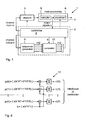
- a data storage system incorporating an embodiment of impulse response identification apparatus is illustrated schematically in Figure 1 .
- the data storage system is a tape drive 1 and includes impulse response identification apparatus in the form of response analysis module 2 which implements a response identification method embodying the invention.
- the data channel here is thus a magnetic recording channel 3 comprising a read/write head for recording data on, and reading data from, a magnetic tape.
- data is recorded in channel 3 with a recording data rate of 1/T.
- Readback signals output by the read/write head are supplied to read processing apparatus indicated generally at 4.
- Read processing apparatus 4 is shown in simplified form in the figure as including a sampler 5 and an equalizer 6 to which particular reference will be made in describing operation of response analysis module 2.
- read processing circuitry typically includes various other components (not shown) for performing functions such as automatic gain control, low-pass filtering, sequence detection, decoding and error correction.
- the write-processing apparatus on the recording side of channel 3 is omitted from the figure for simplicity, but typically includes components performing functions such as encoding, partial response precoding, write equalization and write-precompensation.
- Impulse response analysis module 2 consists of a controller 8, a sequence generator 9 and a correlator 10 as indicated in the figure.
- the controller 8 in this embodiment can control read/write operations of channel 3, and also aspects of the operation of equalizer 6. More specifically, controller 8 can effect a read/write operation the results of which can be processed in analysis module 2 to identify the impulse response (here the pulse, or dibit, response) of channel 3, and also to compute values for the coefficients of equalizer 6 appropriate to that response.
- the controller 8 controls recording in channel 3 of an input sequence a and controls the read/write head to read the recorded sequence.
- Readback signals from the channel are oversampled by sampler 5 and the resulting sampled channel output signals y are received by controller 8 as indicated in the figure. Controller 8 averages these sampled output signals y to produce an average channel output sequence z.
- the polyphase sequences p(j) are output to correlator 10 which also receives an input sequence b from controller 8.
- Controller 8 generates the sequence b from the original channel input a by decimating the sequence a by q (q being 4 in this example).
- Correlator 10 correlates each polyphase sequence p(j) with the decimated input sequence b and accumulates the correlation results to produce a correlated output sequence c ( j ).
- the correlated output sequences are then supplied to controller 8 which interleaves these sequences to produce the impulse response of recording channel 3. This is further processed in controller 8 to derive appropriate coefficients for equalizer 6 which are then output to the equalizer for use in subsequent operation of the tape drive.
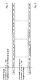
- the channel input sequence a supplied by controller 8 to initiate the above process is illustrated schematically in Figure 2 .
- PRBS patterns may be employed here and suitable examples will be apparent to those skilled in the art.
- the decimated binary sequence b is illustrated in Figure 3 .
- Controller 8 produces this sequence from the channel input a by selecting every q th symbol of sequence a . In this example therefore controller 8 selects every 4 th symbol of sequence a .
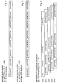
- a sampled channel output signal y is obtained as shown in Figure 4 .
- the input sequence a is periodically repeated, here M times, to produce M output signals y .
- Controller 8 then averages these signals to produce the channel output sequence z shown in Figure 5 .
- the value of M may be selected as required in a given system, but a typical value for M might be 10.
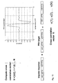
- each polyphase sequence is produced by selecting every 5 th sample of the channel output z , with a phase shift of one sample between successive polyphase sequences.
- the resulting polyphase sample sequences p ( 0 ) to p(4) are illustrated in Figure 6 .
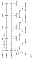
- Figure 7 further illustrates the polyphase sample timings relative to the basic sequence z in comparison to the original input sequence a and the decimated sequence b .
- the input symbols shown in bold at the top represent the decimated sequence symbols b , and it can be seen that these are coincident in time with the samples of polyphase sequence p(0).
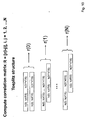
- the polyphase sequences p ( 0 ) to p(4) are supplied by sequence generator 9 to correlator 10 which also receives the decimated sequence b from controller 8.
- the process of correlating two signals involves multiplication of each successive sample of one signal with the respective corresponding sample of the other signal, as indicated by the multipliers shown in the figure. However, because the input binary values are ⁇ 1 here, the multiplication process merely involves a change of sign. The multiplication of real numbers, and hence the need for true multipliers, is therefore avoided in the correlation process.
- the correlated output signals c ( 0 ) to c ( 4 ) are supplied sample-by-sample to controller 8 which interleaves the signals in phase order of the corresponding polyphase sequences p(j). That is, the correlated signal samples are interleaved in the order:
- MMSE minimum mean-square error equalizer coefficients
- I the identity matrix
- R ns the correlation matrix of the colored noise
- ⁇ 2 a small positive constant that is added across the diagonal of the channel correlation matrix. This is done because it is often impractical to compute the correlation properties of the additive noise, and improves the out-of-band noise rejection properties as well as reducing noise enhancement.
- the resulting coefficients derived by controller 8 are supplied to equalizer 6 for use in subsequent operation of the storage device.
- the response analysis module 2 operates to identify the oversampled channel impulse response by a highly efficient process involving a simple, multiplication-free correlation method. This offers simple, high-speed operation which can be readily implemented in both hardware and software.
- the functional blocks 8, 9 and 10 of module 2 may be implemented in hardware, software or a combination thereof as desired in a given system.
- the functionality of module 2 may be included as part of the C-code currently used for initial equalizer computation.
- module 2 allows fast and accurate computation of the equalizer coefficients, and may be employed during manufacture of the tape drive 1 and/or may be a "built-in" module whose operation can be invoked when required. For example, if the drive is damaged a "retraining" mode may be invoked whereby the module 2 operates to recalculate the equalizer coefficients. The retraining mode may also be invoked to deal with changes in the impulse response due to aging of the tape.
- the impulse response may be further processed to determine appropriate values for various other parameters of the processing apparatus 6, e.g. parameters of the detection circuitry.
- the impulse response may be utilized in further processing for the identification and measurement of non-linearities and bit-shift during a special off-line procedure of the tape drive.
- the identified response may also be utilized in noise component characterization and separation functions, whether additive stationary noise, additive colored noise or media noise (transition noise and data-dependent noise).
- the dibit response obtained in the embodiment described may be further processed in controller 8 to identify the step (transition) response of the channel. This can be achieved in known manner and implementations of this processing will be apparent to those skilled in the art.
- the transition response is generally approximated using a Lorentzian model, and minimum mean-square error methods are usually adopted to obtain the parameters of the Lorentzian model from the dibit response.
- the step response may then be utilized in various additional processing operations as described above.
- the highly efficient nature of the response extraction process described above offers considerably faster computation of channel parameters compared to existing on-line or off-line methods.
- the response analysis apparatus may include its own sampler allowing readback signals to be received directly from the channel.
- the controller 8 may be embodied in a more general controller which controls various aspects of the device operation. While the above embodiment is employed in a tape drive, embodiments of the invention may be employed to identify the impulse response of other oversampled data channels, e.g. in other data storage systems such as disk drives, or in data communications systems. In the latter case operation is generally as described above for recording channel 3, except the controller 8 would of course receive output signals from a receiver mechanism connected to the communications channel.
Landscapes
- Engineering & Computer Science (AREA)
- Signal Processing (AREA)
- Computer Networks & Wireless Communication (AREA)
- Power Engineering (AREA)
- Signal Processing For Digital Recording And Reproducing (AREA)
- Cable Transmission Systems, Equalization Of Radio And Reduction Of Echo (AREA)
- Digital Magnetic Recording (AREA)
Claims (15)
- Verfahren zum Ermitteln der Impulsantwort eines Datenkanals (3), wobei das Verfahren Folgendes umfasst:Zuführen eines Eingangssignals (a) zum Kanal (3), das eine binäre Pseudo-Zufallsfolge von L Symbolen mit einer Symbolrate von 1/T umfasst;Erzeugen eines Kanalausgangssignals (z) durch Abtasten eines dem Eingangssignal (a) entsprechenden Kanalausgangssignals mit einem Abtastintervall TS = (q/p)T, wobei q und p relative Primzahlen mit q < p und q und L relative Primzahlen sind;Erzeugen von p Polyphasenfolgen (p(j)) aus dem Kanalausgangssignal (z) durch Auswählen von jedem p-ten Abtastwert des Ausgangssignals (z) für jede Polyphasenfolge (p(j)) mit einer Phasenverschiebung von einem Abtastwert zwischen aufeinanderfolgenden Polyphasenfolgen (p(j));Erzeugen einer dezimierten binären Folge (b) durch Auswählen von jedem q-ten Symbol des Kanaleingangssignals (a);Korrelieren dieser Polyphasenfolge mit der dezimierten binären Folge (b) für jede Polyphasenfolge (p(j)), wobei die beiden möglichen binären Werte für die Korrelation gleich groß sind und ein entgegengesetztes Vorzeichen aufweisen, und Kumulieren der Korrelationsergebnisse, um eine korrelierte Ausgangsfolge (c(j)) zu erzeugen; undVerschachteln von Abtastwerten der korrelierten Ausgangsfolgen (c(j)) in der Phasenreihenfolge der entsprechenden Polyphasenfolgen (p(j)), um die Impulsantwort des Kanals zu erzeugen.
- Verfahren nach Anspruch 1, wobei es sich bei dem Datenkanal (3) um einen magnetischen Aufzeichnungskanal handelt, wobei das Kanaleingangssignal (a) im Aufzeichnungskanal aufgezeichnet wird und die erzeugte Impulsantwort die Impulsantwort des Aufzeichnungskanals ist.
- Verfahren zum Ermitteln der Schrittantwort eines magnetischen Aufzeichnungskanals (3), wobei das Verfahren Folgendes umfasst:Ermitteln der Impulsantwort des Aufzeichnungskanals (3) durch ein Verfahren nach Anspruch 2, undVerarbeiten der Impulsantwort, um die Schrittantwort zu erzeugen.
- Verfahren nach Anspruch 1, wobei der Datenkanal ein Übertragungskanal ist.
- Verfahren nach irgendeinem vorhergehenden Anspruch, wobei das Kanalausgangssignal (z) durch Abtasten einer Vielzahl von dem Eingangssignal (a) entsprechenden Kanalausgangssignalen mit dem Abtastintervall Ts und anschließendes Bilden des Mittelwertes der abgetasteten Ausgangssignale (y) erzeugt wird.
- Verfahren nach irgendeinem vorhergehenden Anspruch, wobei das Kanaleingangssignal (a) eine periodische Folge umfasst, bei der jede Periode die binäre Zufallsfolge aus L Symbolen umfasst.
- Verfahren nach Anspruch 6, wobei das Kanaleingangssignal (a) q Perioden der binären Pseudo-Zufallsfolge umfasst.
- Verfahren nach irgendeinem vorhergehenden Anspruch, wobei L = 63, q = 4 und p = 5.
- Verfahren zum Bestimmen von einem oder mehreren Parametern der Signalverarbeitungsvorrichtung (4) zum Verarbeiten von Ausgangssignalen von einem Datenkanal (3), wobei das Verfahren Folgendes umfasst:Ermitteln der Antwort des Datenkanals (3) durch ein Verfahren nach irgendeinem vorhergehenden Anspruch, undVerarbeiten der Antwort, um für jeden Parameter in Abhängigkeit von dieser Antwort einen Wert abzuleiten.
- Verfahren nach Anspruch 9 zum Bestimmen von Koeffizienten für einen Entzerrer (6) der Signalverarbeitungsvorrichtung (4), wobei das Verfahren das Verarbeiten der Impulsantwort des Datenkanals (3) umfasst, um Koeffizienten für den Entzerrer (6) abzuleiten, die für diese Impulsantwort geeignet sind.
- Computerprogramm, das ein Programmcodemittel umfasst, um einen Computer zu veranlassen, das Verfahren nach irgendeinem vorhergehenden Anspruch auszuführen.
- Vorrichtung (2) zum Ermitteln der Impulsantwort eines magnetischen Aufzeichnungskanals (3) in einer Datenspeichereinheit (1), in der Daten im Kanal (3) mit einer Symbolrate von 1/T aufgezeichnet und abgetastete Kanalausgangssignale (y) erzeugt werden, indem Rücklesesignale mit einem Abtastintervall Ts = (q/p)T abgetastet werden, wobei p und q relative Primzahlen sind und q < p, wobei die Vorrichtung (2) Folgendes umfasst:eine Steuereinheit (8) zum Steuern der Aufzeichnung eines Kanaleingangssignals (a), das eine binäre Pseudo-Zufallsfolge von L Symbolen umfasst, und zum Erzeugen einer dezimierten binären Folge (b) durch Auswählen von jedem q-ten Symbol des Kanaleingangssignals (a), wobei q und L relative Primzahlen sind;einen Folgengenerator (9) zum Erzeugen von p Polyphasenfolgen (p(j)) aus einem dem Eingangssignal (a) entsprechenden Kanalausgangssignal (z), wobei jede Polyphasenfolge (p(j)) durch Auswählen von jedem p-ten Abtastwert des Ausgangssignals (z) mit einer Phasenverschiebung von einem Abtastwert zwischen aufeinanderfolgenden Polyphasenfolgen (p(j)) erzeugt wird; undeinen Korrelator (10) zum Korrelieren jeder Polyphasenfolge (p(j)) mit der dezimierten binären Folge (b), wobei die beiden möglichen binären Werte für die Korrelation gleich groß sind und ein entgegengesetztes Vorzeichen aufweisen, und zum Kumulieren der Korrelationsergebnisse, um eine korrelierte Ausgangsfolge (c(j)) für diese Polyphasenfolge (p(j)) zu erzeugen;wobei die Steuereinheit geeignet ist, Abtastwerte der korrelierten Ausgangsfolgen (c(j)) in der Phasenreihenfolge der entsprechenden Polyphasenfolgen (p(j)) zu verschachteln, um die Impulsantwort des Aufzeichnungskanals (3) zu erzeugen.
- Vorrichtung nach Anspruch 12, wobei die Steuereinheit (8) geeignet ist, das Lesen des aufgezeichneten Kanaleingangssignals (a) eine Vielzahl von Malen zu steuern, um eine entsprechende Vielzahl von abgetasteten Kanalausgangssignalen (y) zu erzeugen, um den Mittelwert der abgetasteten Kanalausgangssignale (y) zu bilden, um das Kanalausgangssignal (z) zu erzeugen und um das Kanalausgangssignal (z) dem Folgengenerator (9) zuzuführen.
- Vorrichtung zum Ermitteln der Impulsantwort eines Datenübertragungskanals, wenn ein Kanaleingangssignal (a), das eine binäre Pseudo-Zufallsfolge von L Symbolen umfasst, mit einer Symbolrate von 1/T über den Kanal übertragen wird und das empfangene Signal mit einem Abtastintervall Ts = (q/p)T abgetastet wird, um ein abgetastetes Kanalausgangssignal (y) zu erzeugen, wobei q und p relative Primzahlen mit q < p sind, und q und L relative Primzahlen sind, wobei die Vorrichtung Folgendes umfasst:einen Folgengenerator (9) zum Erzeugen von p Polyphasenfolgen (p(j)) aus einem dem Kanaleingangssignal (a) entsprechenden Kanalausgangssignal (z), wobei jede Polyphasenfolge (p(j)) durch Auswählen von jedem p-ten Abtastwert des Ausgangssignals (z) mit einer Phasenverschiebung von einem Abtastwert zwischen aufeinanderfolgenden Polyphasenfolgen (p(j)) erzeugt wird;eine Steuereinheit (8) zum Erzeugen einer dezimierten binären Folge (b), die jedes q-te Symbol des Kanaleingangssignals (a) umfasst; undeinen Korrelator (10) zum Korrelieren jeder Polyphasenfolge (p(j)) mit der dezimierten binären Folge (b), wobei die beiden möglichen binären Werte für die Korrelation gleich groß sind und ein entgegengesetztes Vorzeichen aufweisen, und zum Kumulieren der Korrelationsergebnisse, um eine korrelierte Ausgangsfolge (c(j)) für diese Polyphasenfolge (p(j)) zu erzeugen;wobei die Steuereinheit geeignet ist, Abtastwerte der korrelierten Ausgangsfolgen (c(j)) in der Phasenreihenfolge der entsprechenden Polyphasenfolgen (p(j)) zu verschachteln, um die Impulsantwort des Kanals zu erzeugen.
- Vorrichtung nach Anspruch 14, wobei das Kanaleingangssignal (a) eine Vielzahl von Malen über den Kanal übertragen wird, um eine entsprechende Vielzahl von abgetasteten Kanalausgangssignalen (y) zu erzeugen, und wobei die Steuereinheit geeignet ist, den Mittelwert der abgetasteten Kanalausgangssignale (y) zu bilden, um das Kanalausgangssignal (z) zu erzeugen und um das Kanalausgangssignal dem Folgengenerator (9) zuzuführen.
Applications Claiming Priority (2)
| Application Number | Priority Date | Filing Date | Title |
|---|---|---|---|
| US11/558,949 US7760821B2 (en) | 2006-11-13 | 2006-11-13 | Oversampled channel response identification |
| PCT/IB2007/054535 WO2008059406A1 (en) | 2006-11-13 | 2007-11-08 | Oversampled channel response identification |
Publications (2)
| Publication Number | Publication Date |
|---|---|
| EP2095366A1 EP2095366A1 (de) | 2009-09-02 |
| EP2095366B1 true EP2095366B1 (de) | 2012-08-22 |
Family
ID=38941909
Family Applications (1)
| Application Number | Title | Priority Date | Filing Date |
|---|---|---|---|
| EP07827019A Not-in-force EP2095366B1 (de) | 2006-11-13 | 2007-11-08 | Überabtastungs-kanalantwortidentifikation |
Country Status (6)
| Country | Link |
|---|---|
| US (1) | US7760821B2 (de) |
| EP (1) | EP2095366B1 (de) |
| JP (1) | JP4699555B2 (de) |
| KR (1) | KR101120734B1 (de) |
| CN (1) | CN101536102B (de) |
| WO (1) | WO2008059406A1 (de) |
Families Citing this family (9)
| Publication number | Priority date | Publication date | Assignee | Title |
|---|---|---|---|---|
| US8441751B1 (en) * | 2006-08-18 | 2013-05-14 | Marvell International Ltd. | Dibit pulse extraction methods and systems |
| US8441752B1 (en) * | 2006-08-30 | 2013-05-14 | Marvell International Ltd. | Dibit pulse extraction methods and systems |
| US8208858B2 (en) * | 2008-07-30 | 2012-06-26 | Kan Ling Capital, L.L.C. | Polyphase sequences for wireless communications |
| US8179774B2 (en) * | 2009-01-30 | 2012-05-15 | Lantiq Deutschland Gmbh | Cross-talk coefficient updating in vector transmission |
| US8520719B2 (en) * | 2009-05-29 | 2013-08-27 | Qualcomm Incorporated | Multiple-mode correlator |
| US8149529B2 (en) * | 2010-07-28 | 2012-04-03 | Lsi Corporation | Dibit extraction for estimation of channel parameters |
| US8792196B1 (en) | 2013-03-07 | 2014-07-29 | Western Digital Technologies, Inc. | Disk drive estimating noise in a read signal based on an identified response at the input of an equalizer |
| GB201410641D0 (en) * | 2014-06-13 | 2014-07-30 | Nordic Semiconductor Asa | Radio communication |
| US9929922B2 (en) * | 2016-06-13 | 2018-03-27 | Oracle International Corporation | Sampling-densification technique to facilitate high-sampling-density signatures for telemetry data in enterprise computing systems |
Family Cites Families (12)
| Publication number | Priority date | Publication date | Assignee | Title |
|---|---|---|---|---|
| US6208477B1 (en) | 1997-06-06 | 2001-03-27 | Western Digital Corporation | Hard disk drive having a built-in self-test for measuring non-linear signal distortion |
| US7430257B1 (en) * | 1998-02-12 | 2008-09-30 | Lot 41 Acquisition Foundation, Llc | Multicarrier sub-layer for direct sequence channel and multiple-access coding |
| JP3230482B2 (ja) * | 1998-03-13 | 2001-11-19 | 日本電気株式会社 | 適応等化器 |
| US6937650B2 (en) * | 2001-05-21 | 2005-08-30 | Hitachi Global Storage Technologies Netherlands B.V. | Method and apparatus for channel equalization with a digital FIR filter using a pseudo random sequence |
| JP3921978B2 (ja) * | 2001-09-21 | 2007-05-30 | 日本ビクター株式会社 | 再生装置 |
| US7145972B2 (en) * | 2001-10-18 | 2006-12-05 | The Aerospace Corporation | Polyphase channelization system |
| US7151797B2 (en) * | 2002-05-14 | 2006-12-19 | Limberg Allen Leroy | Adaptive K-factor-improvement filter for receiver of radio signals subject to multipath distortion |
| GB2393618B (en) * | 2002-09-26 | 2004-12-15 | Toshiba Res Europ Ltd | Transmission signals methods and apparatus |
| KR100556389B1 (ko) * | 2003-10-31 | 2006-03-03 | 엘지전자 주식회사 | 잔류측파대 디지털 텔레비전 시스템용 결정궤환 등화기의초기화 방법 및 장치 |
| US7170704B2 (en) * | 2004-06-25 | 2007-01-30 | Stmicroelectronics, Inc. | Enhanced dibit extraction |
| US7245444B2 (en) * | 2005-03-31 | 2007-07-17 | Hitachi Global Storage Technologies Netherlands B.V. | Method and apparatus for providing a read channel having imbedded channel signal analysis |
| US7643238B2 (en) * | 2005-08-29 | 2010-01-05 | Broadcom Corporation | Dibit extraction |
-
2006
- 2006-11-13 US US11/558,949 patent/US7760821B2/en not_active Expired - Fee Related
-
2007
- 2007-11-08 CN CN200780042194XA patent/CN101536102B/zh not_active Expired - Fee Related
- 2007-11-08 EP EP07827019A patent/EP2095366B1/de not_active Not-in-force
- 2007-11-08 WO PCT/IB2007/054535 patent/WO2008059406A1/en not_active Ceased
- 2007-11-08 JP JP2009535860A patent/JP4699555B2/ja not_active Expired - Fee Related
- 2007-11-08 KR KR1020097009453A patent/KR101120734B1/ko not_active Expired - Fee Related
Also Published As
| Publication number | Publication date |
|---|---|
| CN101536102B (zh) | 2011-08-24 |
| US20080137722A1 (en) | 2008-06-12 |
| US7760821B2 (en) | 2010-07-20 |
| CN101536102A (zh) | 2009-09-16 |
| JP2010509702A (ja) | 2010-03-25 |
| EP2095366A1 (de) | 2009-09-02 |
| KR101120734B1 (ko) | 2012-03-22 |
| WO2008059406A1 (en) | 2008-05-22 |
| JP4699555B2 (ja) | 2011-06-15 |
| KR20090086213A (ko) | 2009-08-11 |
Similar Documents
| Publication | Publication Date | Title |
|---|---|---|
| EP2095366B1 (de) | Überabtastungs-kanalantwortidentifikation | |
| US9264264B2 (en) | Systems and methods for filtering a received signal to remove intersymbol interference | |
| US5995561A (en) | Method and apparatus for reducing noise correlation in a partial response channel | |
| US9590803B2 (en) | Timing error processor that uses the derivative of an interpolator function | |
| Caroselli et al. | Improved detection for magnetic recording systems with media noise | |
| US7424074B2 (en) | Optimizing detector target polynomials in read/write channels to achieve best error rate performance in disk drives | |
| CN100358036C (zh) | 信息再生方法和设备 | |
| US5539588A (en) | Magnetic recording/reproducing with added intersymbol interference to obtain a partial-response code | |
| US7245444B2 (en) | Method and apparatus for providing a read channel having imbedded channel signal analysis | |
| US6002730A (en) | Method for detecting data and device therefor of data storing unit | |
| CN101199014A (zh) | 波形均衡控制装置 | |
| EP0777226A2 (de) | Schreibentzerrung für Partial-Response-Kanäle | |
| US7852912B2 (en) | Direct determination equalizer system | |
| Patapoutian | Baseline wander compensation for the perpendicular magnetic recording channel | |
| US8094397B2 (en) | System, method, and computer program product for characterizing media associated with data storage channels | |
| Pozidis | Decomposition of noise sources in recording applications using symbol-rate readback samples | |
| Hwang et al. | Signal model for shingled magnetic recording based on data dependent erase band analysis under track squeeze | |
| Tahara et al. | Optimum design of channel filter for digital magnetic recording | |
| Olcer et al. | Cyclic equalization and channel identification for magnetic tape recording systems using the data set separator | |
| Sarigoz et al. | Performance of dropout correction on real magnetic tape waveforms with dropouts | |
| Silvus et al. | A comparison of detection methods in the presence of nonlinearities | |
| WO1998018128A1 (en) | Method and apparatus for multiplicative noise precompensation for magnetic recordings | |
| JP2004296079A (ja) | 波形等化器及び記録情報再生装置 | |
| JP2001086039A (ja) | 半導体装置及び判定帰還型等化器 | |
| JPH05174316A (ja) | 磁気記録再生方式および装置 |
Legal Events
| Date | Code | Title | Description |
|---|---|---|---|
| PUAI | Public reference made under article 153(3) epc to a published international application that has entered the european phase |
Free format text: ORIGINAL CODE: 0009012 |
|
| 17P | Request for examination filed |
Effective date: 20090609 |
|
| AK | Designated contracting states |
Kind code of ref document: A1 Designated state(s): AT BE BG CH CY CZ DE DK EE ES FI FR GB GR HU IE IS IT LI LT LU LV MC MT NL PL PT RO SE SI SK TR |
|
| DAX | Request for extension of the european patent (deleted) | ||
| GRAP | Despatch of communication of intention to grant a patent |
Free format text: ORIGINAL CODE: EPIDOSNIGR1 |
|
| GRAS | Grant fee paid |
Free format text: ORIGINAL CODE: EPIDOSNIGR3 |
|
| GRAA | (expected) grant |
Free format text: ORIGINAL CODE: 0009210 |
|
| AK | Designated contracting states |
Kind code of ref document: B1 Designated state(s): AT BE BG CH CY CZ DE DK EE ES FI FR GB GR HU IE IS IT LI LT LU LV MC MT NL PL PT RO SE SI SK TR |
|
| REG | Reference to a national code |
Ref country code: GB Ref legal event code: FG4D |
|
| REG | Reference to a national code |
Ref country code: CH Ref legal event code: EP Ref country code: CH Ref legal event code: NV Representative=s name: IBM RESEARCH GMBH ZURICH RESEARCH LABORATORY INTEL |
|
| REG | Reference to a national code |
Ref country code: IE Ref legal event code: FG4D |
|
| REG | Reference to a national code |
Ref country code: AT Ref legal event code: REF Ref document number: 572329 Country of ref document: AT Kind code of ref document: T Effective date: 20120915 |
|
| REG | Reference to a national code |
Ref country code: DE Ref legal event code: R096 Ref document number: 602007024989 Country of ref document: DE Effective date: 20121018 |
|
| REG | Reference to a national code |
Ref country code: GB Ref legal event code: 746 Effective date: 20121029 |
|
| REG | Reference to a national code |
Ref country code: DE Ref legal event code: R084 Ref document number: 602007024989 Country of ref document: DE Effective date: 20120921 |
|
| REG | Reference to a national code |
Ref country code: NL Ref legal event code: VDEP Effective date: 20120822 |
|
| REG | Reference to a national code |
Ref country code: AT Ref legal event code: MK05 Ref document number: 572329 Country of ref document: AT Kind code of ref document: T Effective date: 20120822 |
|
| REG | Reference to a national code |
Ref country code: LT Ref legal event code: MG4D Effective date: 20120822 |
|
| PG25 | Lapsed in a contracting state [announced via postgrant information from national office to epo] |
Ref country code: CY Free format text: LAPSE BECAUSE OF FAILURE TO SUBMIT A TRANSLATION OF THE DESCRIPTION OR TO PAY THE FEE WITHIN THE PRESCRIBED TIME-LIMIT Effective date: 20120822 Ref country code: LT Free format text: LAPSE BECAUSE OF FAILURE TO SUBMIT A TRANSLATION OF THE DESCRIPTION OR TO PAY THE FEE WITHIN THE PRESCRIBED TIME-LIMIT Effective date: 20120822 Ref country code: FI Free format text: LAPSE BECAUSE OF FAILURE TO SUBMIT A TRANSLATION OF THE DESCRIPTION OR TO PAY THE FEE WITHIN THE PRESCRIBED TIME-LIMIT Effective date: 20120822 Ref country code: IS Free format text: LAPSE BECAUSE OF FAILURE TO SUBMIT A TRANSLATION OF THE DESCRIPTION OR TO PAY THE FEE WITHIN THE PRESCRIBED TIME-LIMIT Effective date: 20121222 Ref country code: AT Free format text: LAPSE BECAUSE OF FAILURE TO SUBMIT A TRANSLATION OF THE DESCRIPTION OR TO PAY THE FEE WITHIN THE PRESCRIBED TIME-LIMIT Effective date: 20120822 |
|
| PG25 | Lapsed in a contracting state [announced via postgrant information from national office to epo] |
Ref country code: GR Free format text: LAPSE BECAUSE OF FAILURE TO SUBMIT A TRANSLATION OF THE DESCRIPTION OR TO PAY THE FEE WITHIN THE PRESCRIBED TIME-LIMIT Effective date: 20121123 Ref country code: BE Free format text: LAPSE BECAUSE OF FAILURE TO SUBMIT A TRANSLATION OF THE DESCRIPTION OR TO PAY THE FEE WITHIN THE PRESCRIBED TIME-LIMIT Effective date: 20120822 Ref country code: SE Free format text: LAPSE BECAUSE OF FAILURE TO SUBMIT A TRANSLATION OF THE DESCRIPTION OR TO PAY THE FEE WITHIN THE PRESCRIBED TIME-LIMIT Effective date: 20120822 Ref country code: SI Free format text: LAPSE BECAUSE OF FAILURE TO SUBMIT A TRANSLATION OF THE DESCRIPTION OR TO PAY THE FEE WITHIN THE PRESCRIBED TIME-LIMIT Effective date: 20120822 Ref country code: PT Free format text: LAPSE BECAUSE OF FAILURE TO SUBMIT A TRANSLATION OF THE DESCRIPTION OR TO PAY THE FEE WITHIN THE PRESCRIBED TIME-LIMIT Effective date: 20121224 Ref country code: LV Free format text: LAPSE BECAUSE OF FAILURE TO SUBMIT A TRANSLATION OF THE DESCRIPTION OR TO PAY THE FEE WITHIN THE PRESCRIBED TIME-LIMIT Effective date: 20120822 |
|
| PG25 | Lapsed in a contracting state [announced via postgrant information from national office to epo] |
Ref country code: NL Free format text: LAPSE BECAUSE OF FAILURE TO SUBMIT A TRANSLATION OF THE DESCRIPTION OR TO PAY THE FEE WITHIN THE PRESCRIBED TIME-LIMIT Effective date: 20120822 |
|
| PG25 | Lapsed in a contracting state [announced via postgrant information from national office to epo] |
Ref country code: ES Free format text: LAPSE BECAUSE OF FAILURE TO SUBMIT A TRANSLATION OF THE DESCRIPTION OR TO PAY THE FEE WITHIN THE PRESCRIBED TIME-LIMIT Effective date: 20121203 Ref country code: CZ Free format text: LAPSE BECAUSE OF FAILURE TO SUBMIT A TRANSLATION OF THE DESCRIPTION OR TO PAY THE FEE WITHIN THE PRESCRIBED TIME-LIMIT Effective date: 20120822 Ref country code: RO Free format text: LAPSE BECAUSE OF FAILURE TO SUBMIT A TRANSLATION OF THE DESCRIPTION OR TO PAY THE FEE WITHIN THE PRESCRIBED TIME-LIMIT Effective date: 20120822 Ref country code: DK Free format text: LAPSE BECAUSE OF FAILURE TO SUBMIT A TRANSLATION OF THE DESCRIPTION OR TO PAY THE FEE WITHIN THE PRESCRIBED TIME-LIMIT Effective date: 20120822 Ref country code: EE Free format text: LAPSE BECAUSE OF FAILURE TO SUBMIT A TRANSLATION OF THE DESCRIPTION OR TO PAY THE FEE WITHIN THE PRESCRIBED TIME-LIMIT Effective date: 20120822 |
|
| PG25 | Lapsed in a contracting state [announced via postgrant information from national office to epo] |
Ref country code: IT Free format text: LAPSE BECAUSE OF FAILURE TO SUBMIT A TRANSLATION OF THE DESCRIPTION OR TO PAY THE FEE WITHIN THE PRESCRIBED TIME-LIMIT Effective date: 20120822 Ref country code: PL Free format text: LAPSE BECAUSE OF FAILURE TO SUBMIT A TRANSLATION OF THE DESCRIPTION OR TO PAY THE FEE WITHIN THE PRESCRIBED TIME-LIMIT Effective date: 20120822 Ref country code: SK Free format text: LAPSE BECAUSE OF FAILURE TO SUBMIT A TRANSLATION OF THE DESCRIPTION OR TO PAY THE FEE WITHIN THE PRESCRIBED TIME-LIMIT Effective date: 20120822 |
|
| PLBE | No opposition filed within time limit |
Free format text: ORIGINAL CODE: 0009261 |
|
| REG | Reference to a national code |
Ref country code: CH Ref legal event code: PL |
|
| STAA | Information on the status of an ep patent application or granted ep patent |
Free format text: STATUS: NO OPPOSITION FILED WITHIN TIME LIMIT |
|
| 26N | No opposition filed |
Effective date: 20130523 |
|
| PG25 | Lapsed in a contracting state [announced via postgrant information from national office to epo] |
Ref country code: CH Free format text: LAPSE BECAUSE OF NON-PAYMENT OF DUE FEES Effective date: 20121130 Ref country code: BG Free format text: LAPSE BECAUSE OF FAILURE TO SUBMIT A TRANSLATION OF THE DESCRIPTION OR TO PAY THE FEE WITHIN THE PRESCRIBED TIME-LIMIT Effective date: 20121122 Ref country code: LI Free format text: LAPSE BECAUSE OF NON-PAYMENT OF DUE FEES Effective date: 20121130 |
|
| REG | Reference to a national code |
Ref country code: IE Ref legal event code: MM4A |
|
| REG | Reference to a national code |
Ref country code: DE Ref legal event code: R097 Ref document number: 602007024989 Country of ref document: DE Effective date: 20130523 |
|
| PG25 | Lapsed in a contracting state [announced via postgrant information from national office to epo] |
Ref country code: IE Free format text: LAPSE BECAUSE OF NON-PAYMENT OF DUE FEES Effective date: 20121108 |
|
| PG25 | Lapsed in a contracting state [announced via postgrant information from national office to epo] |
Ref country code: MT Free format text: LAPSE BECAUSE OF FAILURE TO SUBMIT A TRANSLATION OF THE DESCRIPTION OR TO PAY THE FEE WITHIN THE PRESCRIBED TIME-LIMIT Effective date: 20120822 |
|
| PG25 | Lapsed in a contracting state [announced via postgrant information from national office to epo] |
Ref country code: MC Free format text: LAPSE BECAUSE OF NON-PAYMENT OF DUE FEES Effective date: 20121130 Ref country code: TR Free format text: LAPSE BECAUSE OF FAILURE TO SUBMIT A TRANSLATION OF THE DESCRIPTION OR TO PAY THE FEE WITHIN THE PRESCRIBED TIME-LIMIT Effective date: 20120822 |
|
| PG25 | Lapsed in a contracting state [announced via postgrant information from national office to epo] |
Ref country code: LU Free format text: LAPSE BECAUSE OF NON-PAYMENT OF DUE FEES Effective date: 20121108 |
|
| PG25 | Lapsed in a contracting state [announced via postgrant information from national office to epo] |
Ref country code: HU Free format text: LAPSE BECAUSE OF FAILURE TO SUBMIT A TRANSLATION OF THE DESCRIPTION OR TO PAY THE FEE WITHIN THE PRESCRIBED TIME-LIMIT Effective date: 20071108 |
|
| REG | Reference to a national code |
Ref country code: FR Ref legal event code: PLFP Year of fee payment: 9 |
|
| REG | Reference to a national code |
Ref country code: FR Ref legal event code: PLFP Year of fee payment: 10 |
|
| REG | Reference to a national code |
Ref country code: FR Ref legal event code: PLFP Year of fee payment: 11 |
|
| PGFP | Annual fee paid to national office [announced via postgrant information from national office to epo] |
Ref country code: DE Payment date: 20181031 Year of fee payment: 12 |
|
| PGFP | Annual fee paid to national office [announced via postgrant information from national office to epo] |
Ref country code: FR Payment date: 20181120 Year of fee payment: 12 Ref country code: GB Payment date: 20181203 Year of fee payment: 12 |
|
| REG | Reference to a national code |
Ref country code: DE Ref legal event code: R119 Ref document number: 602007024989 Country of ref document: DE |
|
| GBPC | Gb: european patent ceased through non-payment of renewal fee |
Effective date: 20191108 |
|
| PG25 | Lapsed in a contracting state [announced via postgrant information from national office to epo] |
Ref country code: GB Free format text: LAPSE BECAUSE OF NON-PAYMENT OF DUE FEES Effective date: 20191108 Ref country code: DE Free format text: LAPSE BECAUSE OF NON-PAYMENT OF DUE FEES Effective date: 20200603 Ref country code: FR Free format text: LAPSE BECAUSE OF NON-PAYMENT OF DUE FEES Effective date: 20191130 |