EP2094920B1 - Barriere - Google Patents
Barriere Download PDFInfo
- Publication number
- EP2094920B1 EP2094920B1 EP07848562.0A EP07848562A EP2094920B1 EP 2094920 B1 EP2094920 B1 EP 2094920B1 EP 07848562 A EP07848562 A EP 07848562A EP 2094920 B1 EP2094920 B1 EP 2094920B1
- Authority
- EP
- European Patent Office
- Prior art keywords
- barrier
- barrier according
- casing
- bomb
- incident
- Prior art date
- Legal status (The legal status is an assumption and is not a legal conclusion. Google has not performed a legal analysis and makes no representation as to the accuracy of the status listed.)
- Active
Links
- 230000004888 barrier function Effects 0.000 title claims description 166
- 239000002360 explosive Substances 0.000 claims description 43
- 239000000463 material Substances 0.000 claims description 21
- 238000004880 explosion Methods 0.000 claims description 19
- 229910003460 diamond Inorganic materials 0.000 claims description 9
- 239000010432 diamond Substances 0.000 claims description 9
- 230000035939 shock Effects 0.000 claims description 9
- 229920005830 Polyurethane Foam Polymers 0.000 claims description 8
- 239000011496 polyurethane foam Substances 0.000 claims description 8
- 230000002889 sympathetic effect Effects 0.000 claims description 8
- 239000006260 foam Substances 0.000 claims description 7
- 230000000116 mitigating effect Effects 0.000 claims description 7
- 239000004698 Polyethylene Substances 0.000 claims description 3
- 239000006261 foam material Substances 0.000 claims description 3
- -1 polyethylene Polymers 0.000 claims description 3
- 229920000573 polyethylene Polymers 0.000 claims description 3
- 238000000034 method Methods 0.000 claims 1
- 230000000717 retained effect Effects 0.000 claims 1
- 239000000725 suspension Substances 0.000 claims 1
- 239000012634 fragment Substances 0.000 description 25
- 238000005474 detonation Methods 0.000 description 13
- XLYOFNOQVPJJNP-UHFFFAOYSA-N water Substances O XLYOFNOQVPJJNP-UHFFFAOYSA-N 0.000 description 11
- 230000000694 effects Effects 0.000 description 6
- 238000004806 packaging method and process Methods 0.000 description 2
- 241000251729 Elasmobranchii Species 0.000 description 1
- XAGFODPZIPBFFR-UHFFFAOYSA-N aluminium Chemical compound [Al] XAGFODPZIPBFFR-UHFFFAOYSA-N 0.000 description 1
- 229910052782 aluminium Inorganic materials 0.000 description 1
- 239000004411 aluminium Substances 0.000 description 1
- 230000003466 anti-cipated effect Effects 0.000 description 1
- 239000002131 composite material Substances 0.000 description 1
- 230000001419 dependent effect Effects 0.000 description 1
- 230000001066 destructive effect Effects 0.000 description 1
- 230000007613 environmental effect Effects 0.000 description 1
- 238000002474 experimental method Methods 0.000 description 1
- 230000007246 mechanism Effects 0.000 description 1
- 210000001331 nose Anatomy 0.000 description 1
- 230000000149 penetrating effect Effects 0.000 description 1
- 229920003023 plastic Polymers 0.000 description 1
- 239000004033 plastic Substances 0.000 description 1
- 229920002635 polyurethane Polymers 0.000 description 1
- 239000004814 polyurethane Substances 0.000 description 1
- 230000001902 propagating effect Effects 0.000 description 1
- 238000009877 rendering Methods 0.000 description 1
- 230000000979 retarding effect Effects 0.000 description 1
- 230000035945 sensitivity Effects 0.000 description 1
- 238000000926 separation method Methods 0.000 description 1
- 238000007493 shaping process Methods 0.000 description 1
Images


Classifications
-
- B—PERFORMING OPERATIONS; TRANSPORTING
- B64—AIRCRAFT; AVIATION; COSMONAUTICS
- B64D—EQUIPMENT FOR FITTING IN OR TO AIRCRAFT; FLIGHT SUITS; PARACHUTES; ARRANGEMENTS OR MOUNTING OF POWER PLANTS OR PROPULSION TRANSMISSIONS IN AIRCRAFT
- B64D7/00—Arrangements of military equipment, e.g. armaments, armament accessories, or military shielding, in aircraft; Adaptations of armament mountings for aircraft
-
- B—PERFORMING OPERATIONS; TRANSPORTING
- B64—AIRCRAFT; AVIATION; COSMONAUTICS
- B64D—EQUIPMENT FOR FITTING IN OR TO AIRCRAFT; FLIGHT SUITS; PARACHUTES; ARRANGEMENTS OR MOUNTING OF POWER PLANTS OR PROPULSION TRANSMISSIONS IN AIRCRAFT
- B64D45/00—Aircraft indicators or protectors not otherwise provided for
-
- B—PERFORMING OPERATIONS; TRANSPORTING
- B64—AIRCRAFT; AVIATION; COSMONAUTICS
- B64D—EQUIPMENT FOR FITTING IN OR TO AIRCRAFT; FLIGHT SUITS; PARACHUTES; ARRANGEMENTS OR MOUNTING OF POWER PLANTS OR PROPULSION TRANSMISSIONS IN AIRCRAFT
- B64D47/00—Equipment not otherwise provided for
-
- F—MECHANICAL ENGINEERING; LIGHTING; HEATING; WEAPONS; BLASTING
- F41—WEAPONS
- F41H—ARMOUR; ARMOURED TURRETS; ARMOURED OR ARMED VEHICLES; MEANS OF ATTACK OR DEFENCE, e.g. CAMOUFLAGE, IN GENERAL
- F41H11/00—Defence installations; Defence devices
-
- F—MECHANICAL ENGINEERING; LIGHTING; HEATING; WEAPONS; BLASTING
- F41—WEAPONS
- F41H—ARMOUR; ARMOURED TURRETS; ARMOURED OR ARMED VEHICLES; MEANS OF ATTACK OR DEFENCE, e.g. CAMOUFLAGE, IN GENERAL
- F41H13/00—Means of attack or defence not otherwise provided for
-
- F—MECHANICAL ENGINEERING; LIGHTING; HEATING; WEAPONS; BLASTING
- F42—AMMUNITION; BLASTING
- F42B—EXPLOSIVE CHARGES, e.g. FOR BLASTING, FIREWORKS, AMMUNITION
- F42B39/00—Packaging or storage of ammunition or explosive charges; Safety features thereof; Cartridge belts or bags
- F42B39/24—Shock-absorbing arrangements in packages, e.g. for shock waves
-
- F—MECHANICAL ENGINEERING; LIGHTING; HEATING; WEAPONS; BLASTING
- F42—AMMUNITION; BLASTING
- F42D—BLASTING
- F42D5/00—Safety arrangements
- F42D5/04—Rendering explosive charges harmless, e.g. destroying ammunition; Rendering detonation of explosive charges harmless
- F42D5/045—Detonation-wave absorbing or damping means
Definitions
- This invention relates to a barrier and more particularly to a barrier suitable for mitigating the effects of an explosion.
- the blast wave caused by the explosion of a first device can impact a nearby device with enough force to detonate it or at least damage it.
- the blast wave degrades quickly so the risk of devices being detonated falls off quickly with distance.
- the fragments of the exploded device and any other items nearby can become projectiles which radiate out from the device.
- These fragments termed incident material, can impact a device with enough energy to detonate the device.
- the incident material can also cause damage to the device which could render it unstable and vulnerable to detonation.
- the blast wave can lift and/or carry objects in its path which then themselves become projectiles which can damage or detonate other devices.
- An explosive device can be anything from a simple firework to a hi-tech military missile or bomb which contains and explosive material. The detonation of such an explosive device is caused by a shockwave propagating through the explosive material contained within a device. The explosive force is released in a direction perpendicular to the surface of the explosive which is often shaped to follow the internal contours of the device.
- the bomb typically has a casing which has a first end and a second end distal from the first end.
- the first end is a base plate and the second end is often shaped to improve the aerodynamics of the bomb.
- the casing contains an explosive material.
- Fragments from a 1000lb (454.55kg) bomb can be expected to travel side on to a radius of 1.3km and end on (from the base plate) to a radius of 1.65km in an unmitigated event, i.e. an explosion where no barrier is used. As can be expected, it is desirable to prevent the fragments travelling such a distance.
- barriers may be reactive, for example, reactive armour, or passive, which do not have active components.
- Concrete has been employed in the past to make a passive barrier to withstand the destructive force of an explosion, such as the detonation of a bomb.
- barriers made from concrete take time to construct and once constructed are permanent.
- explosive devices such as missiles
- water filled barriers Water is well known in the art for mitigating blasts.
- a water filled barrier may comprise one or more containers filled with water which is/are placed between the explosive device(s) and the item(s) to be protected.
- the water filled barrier overcomes the previous problem as the barrier can be removed after use.
- the barrier needs to be erected where there is an adequate water supply. In an area where a water supply is poor the water to fill the containers needs to be transported.
- the barriers are often bulky which can pose transportation problems and add to the cost of using them.
- the act of filling the containers with water will take time, as will emptying them.
- the resulting blast and shock waves can move this barrier and cause it to impact the item being protected which could result in physical damage to the item which in turn could cause it to detonate or become vulnerable to detonation.
- the barrier in this application was invented by the same inventors as the present barrier. It comprises a portable barrier which is capable of disintegrating harmlessly in the course of its effectiveness. This barrier is suitable for use where the stand-off is about 1 metre or more and has been proven in trials to mitigate against the effect of detonations of various military munitions.
- the barrier addresses the fragments before the shock wave disrupts the barrier.
- the barrier has to deal with the shock wave first which could, in some instances, begin to destroy or disrupt the barrier, thus rendering the item to be protected vulnerable to impact by the blast wave and any incident material.
- the barrier itself can present an impact threat to the item to be protected.
- the invention provides a passive barrier for mitigating blast waves and decelerating incident material to reduce the risk of sympathetic explosions at reduced stand-off distances, which is configured to redirect the force of an incident blast wave and reduce the momentum of any incident material wherein the barrier is constructed of a shock absorbing foam material.
- the barrier according to the invention will fragment which means that as the barrier moves under the force of the blast, it disintegrates and will break up into smaller pieces which are not heavy enough to cause detonation of a nearby device as they do not have a mass great enough to cause damage if they impact a device.
- the barrier can be designed to fully arrest incident material if the sensitivity of the acceptor device requires. Otherwise, it is not always necessary for the barrier to fully arrest the projectiles, but to retard the velocity of the projectiles to such an extent that they no longer present a sympathetic explosion threat and therefore reduce the likelihood of a maximum credible event.
- the barrier according to the present invention can, for example, be used under aircraft where the distance between the explosive devices is less than 1 metre. Due to the preferred material used to construct the barrier, the barrier is able to disintegrate quickly and therefore can be used where the distance between the barrier and the explosive device is less than 1 metre.
- the barrier is advantageously constructed of a polyurethane foam. More advantageously, the foam is a rigid polyurethane foam and is even more advantageously selected from the Last-a-Foam ® FR3700 series produced by General Plastics for packaging purposes which are closed cell rigid polyurethane foams. The density of the foam chosen for a barrier is dependent upon the explosive charge it is to protect against.
- the barrier can be any size depending upon its desired use. For example, it is advantageous to have a barrier which is the same size as or bigger than the device to be protected or to be protected against so as to ensure that as much of the device(s)/items are protected. Also, if the barrier is bigger than the item to be protected then accurate placement of the barrier may not be so crucial. This will of course be advantageous where there is little time to ensure accurate positioning, such as in a conflict situation or where a threat has only just been identified. However, the barrier can be smaller than the explosive device so long as it protects the assessed vulnerable area.
- the shape of the barrier also depends upon its intended use. For example, in the preferred use the barrier is used to protect one bomb from the other under a typical military fighter aircraft as it is not known which, if either, of the bombs is likely to detonate. In this situation the sides of the barrier which are most proximate to the bombs are configured to redirect the force of an incident blast wave. In a situation where an explosive device is to be placed so as to protect a non-explosive device or object, such as a vehicle or a person, it is only necessary for the barrier to be configured to redirect the force of an incident blast wave on the side proximate to the explosive device.
- Shaping the barrier in this way ensures that the blast wave is deflected around the barrier so as to reduce the blast loading on it, thereby reducing the velocity by which the mass of the barrier is driven at the item(s) to be protected and consequently reduces the likelihood of substantial damage to the acceptor munitions at very low standoff distances.
- the barrier is advantageously substantially diamond shape in the cross section perpendicular to a first explosive device.
- the exterior of the barrier forming the diamond cross section can be planar, concave, convex or any other configuration.
- the barrier is shaped to have all four internal angles at about 90°.
- the diamond shape is thought to redirect the blast wave from the explosion around the barrier.
- the loading of the blast wave is deflected from the apex and along the barrier so that the pressure of the wave is spread over a greater area than would be the case with a flat surface. As much of the blast force is deflected there is less force left to move the barrier than with a barrier having a flat surface.
- the diamond shape causes the fragments of the exploded device to move at different velocities and hence the fragments and barrier do not move together at the same speed.
- the barrier will be of particular use in situations where there are reduced standoff distances e.g. under a typical military fighter aircraft.
- the barrier may be suspended from the central pylon of the aircraft to locate it centrally between the two bombs.
- the barrier may be mounted or supported in a frame, holder or on wheels whereby it can be manoeuvred into place.
- the barrier is mounted or supported in a frame which is capable of being manoeuvred into place quickly and easily.
- the frame may have height adjusting means so that it may fit under an empty or laden aircraft such that the barrier itself is aligned with the explosive device or item to be protected. This may be achieved by spring loading the frame or by jacking or other such height adjusting means.
- the frame may further comprise braking or choking means for maintaining it in place.
- the frame can be made of any suitable material for use in a number of environmental conditions.
- the barrier may also be used to protect weapons on different aircraft. Again, the barrier can be placed where it is needed.
- the barrier may have a casing to support it and to provide protection from minor impact damage. It is further advantageous that the casing is water tight.
- the casing may enclose the entirety of the barrier or may partially surround the barrier to afford it some protection from being handled, the environment in which it is used and the weather.
- the casing may fit closely around the barrier or there may be an airgap formed between the casing and the barrier, as is evident with the square configuration shown in figure 4 . It has been shown that if a small airgap exists between the barrier and the outer casing there is no effect on the performance of the barrier.
- a preferred material for the casing is polyethylene but any suitable material can be used. Further, it is advantageous that the polyethylene is about 10mm thick.
- the barrier casing may include stiffening means which can support the barrier.
- the barrier with casing may be mounted or supported in a frame or holder as previously described.
- the barrier can be placed between torpedoes in a submarine, between stationary vehicles carrying explosive devices or in civil or military explosives stores.
- the barrier can also be used in a vehicle for transporting and/or storing explosives.
- the barrier can further be used to surround a vehicle or vehicles to afford them increased protection.
- the barrier could also be used for packaging explosives or explosive devices for transportation and storage.
- Fig. 1 shows the barrier 10 suspended from the underside of an aeroplane 12 which is positioned between two bombs 14.
- the barrier is in the advantageous diamond cross section configuration which will provide protection to/from detonation of either bomb 14.
- Fig. 2 is a plan view of the barrier 10 from above, which is positioned halfway between two bombs 14.
- the barrier 10 is centred between the two bombs parallel with the side faces of the barrier 11 and aligned so that the noses 16 and bases 18 of the bombs are shielded from one another by the barrier 10.
- the barrier is placed halfway between the two bombs so as to protect one from the other.
- the distance between the bombs ( x ) is only 0.78 metres under a typical military fighter aircraft.
- Fig. 3 shows the barrier 10 surrounded by a casing 20 which is shaped to follow the contours of the barrier (shown in a broken line) closely.
- the casing is close fitting but has been shown with a small airgap for clarity of drawing.
- Fig. 4 shows the barrier 10 with a square casing 22. There is an airgap around the barrier due to the square shape of the casing 22 relative to the diamond shape of the barrier 10.
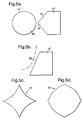
- Fig. 5a shows a barrier 10' having an angled side 13 proximate to an explosive device 14'.
- the apex 24 of the angled side aligns with the centre line 26 of the device 14'.
- Fig. 5b shows a barrier 10" having a slope 28 which will direct the blast wave upwards, as shown by the dotted line.
- the barrier 10" can be inverted so that the slope 28 will redirect the blast wave downwards.
- Fig. 5c and 5d show the exterior of the barrier 10 having concave and convex configuration whilst still maintaining a substantially diamond shaped cross section.
- Trials have proven the success of a barrier according to the present invention when used to protect against the detonation of a 1000lb (454.55kg) bomb.
- the trial was set up to replicate the use of the barrier under a typical military fighter aircraft with the separation between the bombs being 0.78m and having a barrier with a diamond cross section midway between the two.
- One of the 1000lb (454,55kg) bombs was filled with concrete to be an acceptor bomb so that the effects of stand-off distance, barrier thickness, mass and the physical damage imparted to the concrete filled bomb could be analysed and recorded after the controlled detonation of a live bomb to see how much damage was caused to the device.
- Polyurethane barriers with various nominal crush strengths were tested as is shown in table 1.
- the inventors used a live donor bomb, which was detonated remotely, and a live acceptor bomb, each separated from the other by a distance of 0.78m with a 17.5MPa crush strength foam barrier placed between them.
- the barrier mitigated against a sympathetic detonation by retarding the velocity of the fragments and lessening the effects of the blast wave. Only a few fragment scuff marks were visible on the acceptor bomb casing and there was no significant distortion. It was evident that the damage was minimal and so the acceptor bomb was unreacted with minimum damage. After detonation of the bombs there were no remains of the barriers.
- the crush strength of the rigid polyurethane foam depends upon the size of the possible explosive event, the weapon fragment type and the distance between munitions.
- the preferred crush strength of the polyurethane foam is from 5MPa to 17.5MPa and is advantageously in the range of from 12.5MPa to 17.5MPa.
- the barrier used in the trials had dimensions of 350mmx350mmx 1350mm and weighed approximately 36kg. However, the barrier can be shaped or sized to the required size which the skilled man would be able to determine. The barrier could be made to the exact required dimensions, but this would mean that it is down to the operator to position it in the exact location for maximum protection. In a conflict situation this is not ideal as precious time could be lost. It is therefore envisaged that the barriers used will be larger than the devices they are protecting from or protecting against detonating.
Claims (17)
- Passive Barriere (10, 10', 10") zum Abschwächen von Druckexplosionen und zum Abbremsen von auftreffendem Material, um das Risiko sympathetischer Explosionen bei verminderten Sicherheitsabständen zu senken, wobei die Barriere aus einem schockdämpfenden Schaummaterial gefertigt ist, dadurch gekennzeichnet, dass die Barriere so ausgebildet ist, dass die Kraft einer auftreffenden Druckwelle umgelenkt wird und die Wucht eines auftreffenden Materials abgeschwächt wird.
- Barriere nach Anspruch 1, wobei die Barriere aus einem schockdämpfenden Polyurethanschaum gebildet ist.
- Barriere nach Anspruch 2, wobei die Barriere aus einem steifen Polyurethanschaum gebildet ist.
- Barriere nach einem der vorhergehenden Ansprüche, wobei die Barriere einen in etwa rautenförmigen Querschnitt aufweist.
- Barriere nach einem der vorhergehenden Ansprüche, wobei die Barriere eine Druckfestigkeit im Bereich von 5 bis 17,5 MPa aufweist.
- Barriere nach Anspruch 5, wobei die bevorzugte Schaumdruckfestigkeit zum Abschwächen einer Explosion einer 1000 lb (454,55 kg)- Bombe bei einem Abstand von weniger als 1 m 17,5 MPa beträgt.
- Barriere nach einem der vorhergehenden Ansprüche, wobei die Barriere ein Gehäuse (20) aufweist.
- Barriere nach Anspruch 7, wobei sich das Gehäuse (20) um zumindest einen Teil der Barriere herum erstreckt.
- Barriere nach Anspruch 7 oder Anspruch 8, wobei die Form des Gehäuses (20) der Form der Barriere entspricht.
- Barriere nach einem der Ansprüche 7 bis 9, wobei das Gehäuse (20) ein Quader ist.
- Barriere nach einem der Ansprüche 7 bis 10, wobei das Gehäuse (20) aus Polyethylen gefertigt ist.
- Barriere nach einem der Ansprüche 7 bis 11, wobei das Gehäuse (20) ferner Versteifungsmittel aufweist.
- Barriere nach einem der vorhergehenden Ansprüche, wobei die Barriere an dem zentralen Pylon eines Flugzeugs (12) aufgehängt ist.
- Barriere nach einem der Ansprüche 1 bis 12, wobei die Barriere an einem Rahmen oder einer Halterung befestigt ist oder von diesen getragen wird.
- Barriere nach einem der vorhergehenden Ansprüche, wobei die Barriere mit Hilfe eines Ständers, einer Halterung oder einer Aufhängung in Position gehalten wird.
- Barriere nach einem der vorhergehenden Ansprüche, wobei die Barriere ferner Räder zur Unterstützung der Positionierung aufweist.
- Verfahren zur Verwendung einer Barriere nach einem der vorhergehenden Ansprüche, wobei das Verfahren ein Positionieren der Barriere zwischen einem Sprengkörper und einem zu schützenden Gegenstand umfasst.
Applications Claiming Priority (3)
| Application Number | Priority Date | Filing Date | Title |
|---|---|---|---|
| PCT/GB2006/004722 WO2007068954A1 (en) | 2005-12-17 | 2006-12-18 | A barrier |
| GB0711405A GB2445037B (en) | 2006-12-18 | 2007-06-13 | A barrier |
| PCT/GB2007/004822 WO2008075008A2 (en) | 2006-12-18 | 2007-12-17 | A barrier |
Publications (2)
| Publication Number | Publication Date |
|---|---|
| EP2094920A2 EP2094920A2 (de) | 2009-09-02 |
| EP2094920B1 true EP2094920B1 (de) | 2016-09-28 |
Family
ID=41467320
Family Applications (1)
| Application Number | Title | Priority Date | Filing Date |
|---|---|---|---|
| EP07848562.0A Active EP2094920B1 (de) | 2006-12-18 | 2007-12-17 | Barriere |
Country Status (7)
| Country | Link |
|---|---|
| EP (1) | EP2094920B1 (de) |
| CN (1) | CN101583770B (de) |
| BR (1) | BRPI0720534A2 (de) |
| GB (1) | GB2445037B (de) |
| HK (1) | HK1133447A1 (de) |
| RU (1) | RU2009127494A (de) |
| WO (1) | WO2008075008A2 (de) |
Families Citing this family (1)
| Publication number | Priority date | Publication date | Assignee | Title |
|---|---|---|---|---|
| WO2013044171A1 (en) * | 2011-09-23 | 2013-03-28 | Mark Benson | Explosive disruption container |
Family Cites Families (11)
| Publication number | Priority date | Publication date | Assignee | Title |
|---|---|---|---|---|
| GB609456A (en) * | 1946-04-15 | 1948-09-30 | Martin James | Securing and releasing detachable containers of aircraft |
| DE954995C (de) * | 1954-10-27 | 1956-12-27 | Nelsbach & Co | Luftschutzdeckung aus Betonelementen |
| IL59817A (en) * | 1980-04-13 | 1982-11-30 | Koor Metals Ltd | Diagonal joint of skins for protective walls against blast and fragments |
| BR9007004A (pt) * | 1989-11-08 | 1992-01-28 | Royal Ordnance Plc | Material composito utilizavel na absorcao dos efeitos e fragmentos produzidos por uma explosao |
| US5814250A (en) * | 1996-09-18 | 1998-09-29 | The United States Of America As Represented By The Secretary Of The Navy | Method of protecting a structure |
| NL1005707C2 (nl) * | 1997-04-02 | 1998-10-05 | Fokker Special Products | Afscherminrichting voor explosieven. |
| US6216579B1 (en) * | 1998-10-15 | 2001-04-17 | Her Majesty The Queen In Right Of Canada, As Represented By The Solicitor General Acting Through The Commissioner Of The Royal Mounted Canadian Police | Composite armor material |
| FR2792623B1 (fr) * | 1999-04-23 | 2001-06-15 | Giat Ind Sa | Conteneur de securite pour le transport et/ou le stockage d'engins explosifs |
| GB2355057A (en) * | 1999-09-09 | 2001-04-11 | Post Office | Bomb containment device |
| US7687147B2 (en) * | 2004-09-15 | 2010-03-30 | Specialty Products, Inc. | Composite article providing blast mitigation and method for manufacturing same |
| US7736729B2 (en) * | 2005-08-12 | 2010-06-15 | Touchstone Research Laboratory, Ltd | Blast energy mitigating composite |
-
2007
- 2007-06-13 GB GB0711405A patent/GB2445037B/en not_active Expired - Fee Related
- 2007-12-17 RU RU2009127494/03A patent/RU2009127494A/ru unknown
- 2007-12-17 EP EP07848562.0A patent/EP2094920B1/de active Active
- 2007-12-17 WO PCT/GB2007/004822 patent/WO2008075008A2/en active Application Filing
- 2007-12-17 BR BRPI0720534-1A patent/BRPI0720534A2/pt not_active IP Right Cessation
- 2007-12-17 CN CN2007800468823A patent/CN101583770B/zh not_active Expired - Fee Related
-
2010
- 2010-01-18 HK HK10100501.0A patent/HK1133447A1/xx not_active IP Right Cessation
Also Published As
| Publication number | Publication date |
|---|---|
| WO2008075008A3 (en) | 2008-08-07 |
| WO2008075008A2 (en) | 2008-06-26 |
| GB0711405D0 (en) | 2007-07-25 |
| CN101583770B (zh) | 2011-08-24 |
| GB2445037B (en) | 2010-09-29 |
| GB2445037A (en) | 2008-06-25 |
| HK1133447A1 (en) | 2010-03-26 |
| CN101583770A (zh) | 2009-11-18 |
| RU2009127494A (ru) | 2011-01-27 |
| WO2008075008A8 (en) | 2009-10-29 |
| BRPI0720534A2 (pt) | 2013-12-31 |
| EP2094920A2 (de) | 2009-09-02 |
Similar Documents
| Publication | Publication Date | Title |
|---|---|---|
| CA2671534A1 (en) | A barrier | |
| US6957602B1 (en) | Parachute active protection apparatus | |
| KR101194295B1 (ko) | 반응성 보호 장치 | |
| US20100000399A1 (en) | Barrier | |
| US10837740B2 (en) | Reactive armor | |
| AU2022203168A1 (en) | Reactive armor | |
| GB2392487A (en) | Protection against fast projectiles | |
| US3495532A (en) | Antitank land mine | |
| EP2094920B1 (de) | Barriere | |
| EP3137842B1 (de) | System und verfahren zur neutralisierung von hohlladungsgefahren | |
| EP3999795B1 (de) | Vertikaler explosiver reaktiver panzer, seine konstruktion und betriebsverfahren | |
| US11512930B2 (en) | Reactive armor | |
| CZ283084B6 (cs) | Zařízení pro ochranu stěny před střelami | |
| US8424444B2 (en) | Countermeasure systems including pyrotechnically-gimbaled targeting units and methods for equipping vehicles with the same | |
| JP2011158204A (ja) | 迎撃弾及び迎撃システム | |
| CA3005020A1 (en) | Reactive armor | |
| RU2294866C1 (ru) | Способ защиты космических объектов | |
| KR20230136721A (ko) | 군용차 상부 방어장치 | |
| WO2014125480A1 (en) | Shielding of structures | |
| Dikshit | User Friendly Explosives Reactive Armour a Long term Reality | |
| EA003979B1 (ru) | Устройство реактивной брони | |
| EA002511B1 (ru) | Способ защиты от кумулятивных боеприпасов и устройство для осуществления способа | |
| NO164377B (no) | Panservegg av saakalt aktivt panser. | |
| IL110736A (en) | Reactive protection device against projectiles |
Legal Events
| Date | Code | Title | Description |
|---|---|---|---|
| PUAI | Public reference made under article 153(3) epc to a published international application that has entered the european phase |
Free format text: ORIGINAL CODE: 0009012 |
|
| 17P | Request for examination filed |
Effective date: 20090603 |
|
| AK | Designated contracting states |
Kind code of ref document: A2 Designated state(s): AT BE BG CH CY CZ DE DK EE ES FI FR GB GR HU IE IS IT LI LT LU LV MC MT NL PL PT RO SE SI SK TR |
|
| RIN1 | Information on inventor provided before grant (corrected) |
Inventor name: BARNES, IAN Inventor name: THOMAS, BRYN |
|
| DAX | Request for extension of the european patent (deleted) | ||
| 17Q | First examination report despatched |
Effective date: 20100707 |
|
| REG | Reference to a national code |
Ref country code: DE Ref legal event code: R079 Ref document number: 602007048131 Country of ref document: DE Free format text: PREVIOUS MAIN CLASS: E04H0009040000 Ipc: B64D0007000000 |
|
| GRAP | Despatch of communication of intention to grant a patent |
Free format text: ORIGINAL CODE: EPIDOSNIGR1 |
|
| RIC1 | Information provided on ipc code assigned before grant |
Ipc: F42B 39/24 20060101ALI20160324BHEP Ipc: E04H 9/04 20060101ALI20160324BHEP Ipc: F42D 5/045 20060101ALI20160324BHEP Ipc: B64D 7/00 20060101AFI20160324BHEP |
|
| INTG | Intention to grant announced |
Effective date: 20160414 |
|
| GRAS | Grant fee paid |
Free format text: ORIGINAL CODE: EPIDOSNIGR3 |
|
| GRAA | (expected) grant |
Free format text: ORIGINAL CODE: 0009210 |
|
| AK | Designated contracting states |
Kind code of ref document: B1 Designated state(s): AT BE BG CH CY CZ DE DK EE ES FI FR GB GR HU IE IS IT LI LT LU LV MC MT NL PL PT RO SE SI SK TR |
|
| REG | Reference to a national code |
Ref country code: GB Ref legal event code: FG4D |
|
| REG | Reference to a national code |
Ref country code: CH Ref legal event code: EP |
|
| REG | Reference to a national code |
Ref country code: AT Ref legal event code: REF Ref document number: 832495 Country of ref document: AT Kind code of ref document: T Effective date: 20161015 |
|
| REG | Reference to a national code |
Ref country code: IE Ref legal event code: FG4D |
|
| REG | Reference to a national code |
Ref country code: DE Ref legal event code: R096 Ref document number: 602007048131 Country of ref document: DE |
|
| REG | Reference to a national code |
Ref country code: FR Ref legal event code: PLFP Year of fee payment: 10 |
|
| REG | Reference to a national code |
Ref country code: LT Ref legal event code: MG4D |
|
| PG25 | Lapsed in a contracting state [announced via postgrant information from national office to epo] |
Ref country code: FI Free format text: LAPSE BECAUSE OF FAILURE TO SUBMIT A TRANSLATION OF THE DESCRIPTION OR TO PAY THE FEE WITHIN THE PRESCRIBED TIME-LIMIT Effective date: 20160928 Ref country code: LT Free format text: LAPSE BECAUSE OF FAILURE TO SUBMIT A TRANSLATION OF THE DESCRIPTION OR TO PAY THE FEE WITHIN THE PRESCRIBED TIME-LIMIT Effective date: 20160928 |
|
| PGFP | Annual fee paid to national office [announced via postgrant information from national office to epo] |
Ref country code: DE Payment date: 20161213 Year of fee payment: 10 |
|
| REG | Reference to a national code |
Ref country code: NL Ref legal event code: MP Effective date: 20160928 |
|
| REG | Reference to a national code |
Ref country code: AT Ref legal event code: MK05 Ref document number: 832495 Country of ref document: AT Kind code of ref document: T Effective date: 20160928 |
|
| PG25 | Lapsed in a contracting state [announced via postgrant information from national office to epo] |
Ref country code: SE Free format text: LAPSE BECAUSE OF FAILURE TO SUBMIT A TRANSLATION OF THE DESCRIPTION OR TO PAY THE FEE WITHIN THE PRESCRIBED TIME-LIMIT Effective date: 20160928 Ref country code: LV Free format text: LAPSE BECAUSE OF FAILURE TO SUBMIT A TRANSLATION OF THE DESCRIPTION OR TO PAY THE FEE WITHIN THE PRESCRIBED TIME-LIMIT Effective date: 20160928 Ref country code: NL Free format text: LAPSE BECAUSE OF FAILURE TO SUBMIT A TRANSLATION OF THE DESCRIPTION OR TO PAY THE FEE WITHIN THE PRESCRIBED TIME-LIMIT Effective date: 20160928 Ref country code: GR Free format text: LAPSE BECAUSE OF FAILURE TO SUBMIT A TRANSLATION OF THE DESCRIPTION OR TO PAY THE FEE WITHIN THE PRESCRIBED TIME-LIMIT Effective date: 20161229 |
|
| PGFP | Annual fee paid to national office [announced via postgrant information from national office to epo] |
Ref country code: FR Payment date: 20161222 Year of fee payment: 10 |
|
| PG25 | Lapsed in a contracting state [announced via postgrant information from national office to epo] |
Ref country code: RO Free format text: LAPSE BECAUSE OF FAILURE TO SUBMIT A TRANSLATION OF THE DESCRIPTION OR TO PAY THE FEE WITHIN THE PRESCRIBED TIME-LIMIT Effective date: 20160928 Ref country code: EE Free format text: LAPSE BECAUSE OF FAILURE TO SUBMIT A TRANSLATION OF THE DESCRIPTION OR TO PAY THE FEE WITHIN THE PRESCRIBED TIME-LIMIT Effective date: 20160928 |
|
| PG25 | Lapsed in a contracting state [announced via postgrant information from national office to epo] |
Ref country code: IS Free format text: LAPSE BECAUSE OF FAILURE TO SUBMIT A TRANSLATION OF THE DESCRIPTION OR TO PAY THE FEE WITHIN THE PRESCRIBED TIME-LIMIT Effective date: 20170128 Ref country code: PL Free format text: LAPSE BECAUSE OF FAILURE TO SUBMIT A TRANSLATION OF THE DESCRIPTION OR TO PAY THE FEE WITHIN THE PRESCRIBED TIME-LIMIT Effective date: 20160928 Ref country code: ES Free format text: LAPSE BECAUSE OF FAILURE TO SUBMIT A TRANSLATION OF THE DESCRIPTION OR TO PAY THE FEE WITHIN THE PRESCRIBED TIME-LIMIT Effective date: 20160928 Ref country code: SK Free format text: LAPSE BECAUSE OF FAILURE TO SUBMIT A TRANSLATION OF THE DESCRIPTION OR TO PAY THE FEE WITHIN THE PRESCRIBED TIME-LIMIT Effective date: 20160928 Ref country code: BG Free format text: LAPSE BECAUSE OF FAILURE TO SUBMIT A TRANSLATION OF THE DESCRIPTION OR TO PAY THE FEE WITHIN THE PRESCRIBED TIME-LIMIT Effective date: 20161228 Ref country code: PT Free format text: LAPSE BECAUSE OF FAILURE TO SUBMIT A TRANSLATION OF THE DESCRIPTION OR TO PAY THE FEE WITHIN THE PRESCRIBED TIME-LIMIT Effective date: 20170130 Ref country code: CZ Free format text: LAPSE BECAUSE OF FAILURE TO SUBMIT A TRANSLATION OF THE DESCRIPTION OR TO PAY THE FEE WITHIN THE PRESCRIBED TIME-LIMIT Effective date: 20160928 Ref country code: AT Free format text: LAPSE BECAUSE OF FAILURE TO SUBMIT A TRANSLATION OF THE DESCRIPTION OR TO PAY THE FEE WITHIN THE PRESCRIBED TIME-LIMIT Effective date: 20160928 Ref country code: BE Free format text: LAPSE BECAUSE OF FAILURE TO SUBMIT A TRANSLATION OF THE DESCRIPTION OR TO PAY THE FEE WITHIN THE PRESCRIBED TIME-LIMIT Effective date: 20160928 |
|
| REG | Reference to a national code |
Ref country code: DE Ref legal event code: R097 Ref document number: 602007048131 Country of ref document: DE |
|
| PG25 | Lapsed in a contracting state [announced via postgrant information from national office to epo] |
Ref country code: IT Free format text: LAPSE BECAUSE OF FAILURE TO SUBMIT A TRANSLATION OF THE DESCRIPTION OR TO PAY THE FEE WITHIN THE PRESCRIBED TIME-LIMIT Effective date: 20160928 |
|
| PG25 | Lapsed in a contracting state [announced via postgrant information from national office to epo] |
Ref country code: DK Free format text: LAPSE BECAUSE OF FAILURE TO SUBMIT A TRANSLATION OF THE DESCRIPTION OR TO PAY THE FEE WITHIN THE PRESCRIBED TIME-LIMIT Effective date: 20160928 |
|
| REG | Reference to a national code |
Ref country code: CH Ref legal event code: PL |
|
| PLBE | No opposition filed within time limit |
Free format text: ORIGINAL CODE: 0009261 |
|
| STAA | Information on the status of an ep patent application or granted ep patent |
Free format text: STATUS: NO OPPOSITION FILED WITHIN TIME LIMIT |
|
| 26N | No opposition filed |
Effective date: 20170629 |
|
| PG25 | Lapsed in a contracting state [announced via postgrant information from national office to epo] |
Ref country code: MC Free format text: LAPSE BECAUSE OF FAILURE TO SUBMIT A TRANSLATION OF THE DESCRIPTION OR TO PAY THE FEE WITHIN THE PRESCRIBED TIME-LIMIT Effective date: 20160928 |
|
| REG | Reference to a national code |
Ref country code: IE Ref legal event code: MM4A |
|
| PG25 | Lapsed in a contracting state [announced via postgrant information from national office to epo] |
Ref country code: CH Free format text: LAPSE BECAUSE OF NON-PAYMENT OF DUE FEES Effective date: 20161231 Ref country code: LU Free format text: LAPSE BECAUSE OF NON-PAYMENT OF DUE FEES Effective date: 20161217 Ref country code: LI Free format text: LAPSE BECAUSE OF NON-PAYMENT OF DUE FEES Effective date: 20161231 |
|
| PG25 | Lapsed in a contracting state [announced via postgrant information from national office to epo] |
Ref country code: SI Free format text: LAPSE BECAUSE OF FAILURE TO SUBMIT A TRANSLATION OF THE DESCRIPTION OR TO PAY THE FEE WITHIN THE PRESCRIBED TIME-LIMIT Effective date: 20160928 Ref country code: IE Free format text: LAPSE BECAUSE OF NON-PAYMENT OF DUE FEES Effective date: 20161217 |
|
| PG25 | Lapsed in a contracting state [announced via postgrant information from national office to epo] |
Ref country code: HU Free format text: LAPSE BECAUSE OF FAILURE TO SUBMIT A TRANSLATION OF THE DESCRIPTION OR TO PAY THE FEE WITHIN THE PRESCRIBED TIME-LIMIT; INVALID AB INITIO Effective date: 20071217 Ref country code: CY Free format text: LAPSE BECAUSE OF FAILURE TO SUBMIT A TRANSLATION OF THE DESCRIPTION OR TO PAY THE FEE WITHIN THE PRESCRIBED TIME-LIMIT Effective date: 20160928 |
|
| PG25 | Lapsed in a contracting state [announced via postgrant information from national office to epo] |
Ref country code: TR Free format text: LAPSE BECAUSE OF FAILURE TO SUBMIT A TRANSLATION OF THE DESCRIPTION OR TO PAY THE FEE WITHIN THE PRESCRIBED TIME-LIMIT Effective date: 20160928 |
|
| REG | Reference to a national code |
Ref country code: DE Ref legal event code: R119 Ref document number: 602007048131 Country of ref document: DE |
|
| PG25 | Lapsed in a contracting state [announced via postgrant information from national office to epo] |
Ref country code: MT Free format text: LAPSE BECAUSE OF NON-PAYMENT OF DUE FEES Effective date: 20161217 |
|
| REG | Reference to a national code |
Ref country code: FR Ref legal event code: ST Effective date: 20180831 |
|
| PG25 | Lapsed in a contracting state [announced via postgrant information from national office to epo] |
Ref country code: FR Free format text: LAPSE BECAUSE OF NON-PAYMENT OF DUE FEES Effective date: 20180102 Ref country code: DE Free format text: LAPSE BECAUSE OF NON-PAYMENT OF DUE FEES Effective date: 20180703 |
|
| P01 | Opt-out of the competence of the unified patent court (upc) registered |
Effective date: 20230509 |
|
| PGFP | Annual fee paid to national office [announced via postgrant information from national office to epo] |
Ref country code: GB Payment date: 20231220 Year of fee payment: 17 |