EP2094875B1 - Rotationsbeschickungsvorrichtung für einen schachtofen und verfahren zur aktualisierung solcher vorrichtung - Google Patents
Rotationsbeschickungsvorrichtung für einen schachtofen und verfahren zur aktualisierung solcher vorrichtung Download PDFInfo
- Publication number
- EP2094875B1 EP2094875B1 EP07847379A EP07847379A EP2094875B1 EP 2094875 B1 EP2094875 B1 EP 2094875B1 EP 07847379 A EP07847379 A EP 07847379A EP 07847379 A EP07847379 A EP 07847379A EP 2094875 B1 EP2094875 B1 EP 2094875B1
- Authority
- EP
- European Patent Office
- Prior art keywords
- rotary
- inductor
- stationary
- charging device
- rotatable structure
- Prior art date
- Legal status (The legal status is an assumption and is not a legal conclusion. Google has not performed a legal analysis and makes no representation as to the accuracy of the status listed.)
- Active
Links
Images



Classifications
-
- C—CHEMISTRY; METALLURGY
- C21—METALLURGY OF IRON
- C21B—MANUFACTURE OF IRON OR STEEL
- C21B7/00—Blast furnaces
- C21B7/18—Bell-and-hopper arrangements
- C21B7/20—Bell-and-hopper arrangements with appliances for distributing the burden
-
- F—MECHANICAL ENGINEERING; LIGHTING; HEATING; WEAPONS; BLASTING
- F27—FURNACES; KILNS; OVENS; RETORTS
- F27B—FURNACES, KILNS, OVENS OR RETORTS IN GENERAL; OPEN SINTERING OR LIKE APPARATUS
- F27B1/00—Shaft or like vertical or substantially vertical furnaces
- F27B1/10—Details, accessories or equipment specially adapted for furnaces of these types
- F27B1/20—Arrangements of devices for charging
-
- F—MECHANICAL ENGINEERING; LIGHTING; HEATING; WEAPONS; BLASTING
- F27—FURNACES; KILNS; OVENS; RETORTS
- F27D—DETAILS OR ACCESSORIES OF FURNACES, KILNS, OVENS OR RETORTS, IN SO FAR AS THEY ARE OF KINDS OCCURRING IN MORE THAN ONE KIND OF FURNACE
- F27D3/00—Charging; Discharging; Manipulation of charge
- F27D3/0033—Charging; Discharging; Manipulation of charge charging of particulate material
-
- Y—GENERAL TAGGING OF NEW TECHNOLOGICAL DEVELOPMENTS; GENERAL TAGGING OF CROSS-SECTIONAL TECHNOLOGIES SPANNING OVER SEVERAL SECTIONS OF THE IPC; TECHNICAL SUBJECTS COVERED BY FORMER USPC CROSS-REFERENCE ART COLLECTIONS [XRACs] AND DIGESTS
- Y10—TECHNICAL SUBJECTS COVERED BY FORMER USPC
- Y10T—TECHNICAL SUBJECTS COVERED BY FORMER US CLASSIFICATION
- Y10T29/00—Metal working
- Y10T29/49—Method of mechanical manufacture
- Y10T29/49718—Repairing
Definitions
- the present invention generally relates to a rotary charging device for a shaft furnace such as a metallurgical blast furnace. More particularly, the invention relates to achieving electric energy transfer from the stationary part to the rotatable part of the charging device.
- a rotary charging device for feeding charge material into the furnace.
- Charging devices of the BELL LESS TOP type represent a particularly widespread example.
- Such a rotary charging device typically comprises a variably inclinable chute that is mounted on a rotatable support.
- the variation of the chute inclination is achieved by means of a highly developed drive gear mechanism configured to transfer mechanical work from the stationary to the rotating part for varying the chute inclination.
- EP 0 863 215 it has been proposed to actuate the chute by means of an electrical motor arranged on the rotating part that supports the chute.
- This solution eliminates the need for a highly developed mechanical gear arrangement for varying the chute inclination. It does however require means for electric energy transfer, from the stationary part to the rotatable part, in order to power the electric motor on the rotatable chute support.
- the solution according to EP 0 863 215 is believed not to have found a widespread use because it is incomplete as far as such electric energy transfer is concerned both in terms of reliability despite the harsh blast furnace environment and in terms of low-maintenance requirements of means for achieving electric energy transfer.
- Documents CS0236410 , CS236408 and CS0236536 all relate to an electromagnetic drive for a shaft furnace throat feed chute. These documents disclose different configurations of electric motors for driving the rotary structure of the charging device, in which stator inductors are arranged on the stationary support and rotor inductors are arranged on the rotatable structure.
- Document WO03/050314 which is considered as the closest prior art, discloses a rotary charging device for a shaft furnace, comprising :rotary distribution system, a rotatable structure, supporting said distribution system, a stationary support, supporting said rotatable structure and an electric load arranged on said rotatable structure.
- a slip ring arrangement as commonly found in electrical generators and electric motors, represents a well-known and widespread means for achieving electric energy transfer onto and from a rotatable part.
- Slip rings allow transmitting electric power of virtually any wattage to a rotating part.
- Their major drawback is that slip rings require frequent maintenance intervention, e.g. for cleaning and often require part replacement because of attrition. It will be understood that wear of slip rings is even more pronounced in the dusty and high temperature environment of a shaft furnace such as a blast furnace.
- the present invention proposes a rotary charging device for a shaft furnace according to claim 1 and a method for upgrading such a charging device according to claim 15.
- a rotary charging device for a shaft furnace typically comprises a rotary distribution means for distributing charge material on a charging surface in the shaft furnace.
- a rotatable structure supports the rotary distribution means.
- the rotatable structure in turn is supported by a stationary support in a manner that allows rotation of this structure.
- the rotary charging device comprises an inductive coupling device.
- This inductive coupling device includes a stationary inductor fixedly mounted to the stationary support and a rotary inductor fixedly mounted to the rotatable structure.
- the stationary and the rotary inductor are separated by a radial gap. They are configured for achieving contact-less electric energy transfer, from the stationary support to the rotatable structure, by means of a shared magnetic field coupled in radial direction trough the gap.
- the inductors constitute a rotary transformer.
- the coupling device provides a maintenance-friendly and reliable means for powering an electric load arranged on said rotary structure and connected to the rotary inductor.
- the rotary transformer-type, inductive coupling device is not subject to wear by attrition and therefore virtually maintenance-free.
- a known circular slip-ring arrangement adapted for a shaft furnace charging device will have a considerable diameter, because of the required central passage for charge material (burden), whereby its wear is even more pronounced.
- This problem is eliminated by virtue of the power transmission device according to the present invention.
- a slightly lesser degree of power transmission efficiency may result from the interferric gap, especially when compared to slip-ring arrangements, this minor drawback is more than compensated by the considerable improvements in reliability and maintenance-friendliness.
- the invention proposes to arrange the interferric gap in radial direction, i.e. opposing the pole faces of the inductors radially with reference to the axis of rotation.
- the range of tolerance for motion of the rotatable structure is normally larger in vertical direction than in radial direction. Therefore, a radially opposed relationship of the inductors allows minimizing the interferric gap.
- the stationary inductor comprises a stationary magnetic core arrangement and that the rotary inductor comprises a rotary magnetic core arrangement.
- the term arrangement is used to clarify that the respective cores need not necessarily be one-piece cores, as will become apparent hereinafter.
- the radial gap separates at least one, in general two or three, magnetic pole faces of the stationary core arrangement from at least one, in general two or three, magnetic pole faces of the rotary core arrangement such that the stationary magnetic pole faces and the rotary magnetic pole faces are arranged in radially opposed relationship.
- the radial gap is substantially vertical, whereby any furnace dust deposits on the opposed faces are virtually impossible. Any dust or other potential deposit can fall through the gap without affecting the functioning of the power-coupling device.
- the stationary inductor and/or the rotary inductor is discontinuous in the direction of rotation.
- the stationary inductor and the rotary inductor are preferably configured such that the total coupling surface for magnetic coupling between the stationary inductor and the rotary inductor is constant during rotation of the rotatable structure.
- a necessary but non-sufficient condition for such constant coupling with discontinuous inductors is that at least one of the stationary inductor and the rotary inductor has a geometry that is rotationally symmetrical with respect to the axis of rotation of the rotatable structure.
- the stationary inductor has at least one aperture in its circumference and the rotary inductor comprises at least one pair of separate sectors.
- the aperture has a radian measure ⁇ and each pair of separate sectors is arranged such that the radian measure ⁇ between the bisectors of this pair is such that ⁇ is a divisor of ⁇ or such that ⁇ is a divisor of ⁇ .
- each coil winding, of the stationary inductor and the rotary inductor respectively has a turn number n in the range of 505 ⁇ n ⁇ 500, and preferably 100 ⁇ n ⁇ 200.
- the inductive coupling device allows reliable and maintenance-friendly powering of an electric load, for example an electric motor operatively associated to the distribution chute for varying the angle of inclination of the distribution chute or for rotating the distribution chute about its longitudinal axis, of a cooling circuit pump, or any other electric load of considerable wattage (e.g. ⁇ 500W) arranged on the rotatable structure.
- an electric load for example an electric motor operatively associated to the distribution chute for varying the angle of inclination of the distribution chute or for rotating the distribution chute about its longitudinal axis, of a cooling circuit pump, or any other electric load of considerable wattage (e.g. ⁇ 500W) arranged on the rotatable structure.
- a radio transmitter, receiver or transceiver can be arranged on the rotatable structure for receiving and/or transmitting such signals to/from the load power by the coupling device.
- the present invention is not limited in application to charging devices of the BELL LESS TOP type. Its use is beneficial also with other types of rotary charging devices. It will further be understood that a charging device, upgraded with the described inductive coupling device, is especially suitable for equipping a blast furnace. The skilled person will also appreciate that the disclosed coupling device can be readily retrofitted as an upgrade to existing charging devices without considerable structural modifications of the charging device.
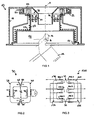
- reference number 10 generally identifies a rotary charging device.
- the rotary charging device 10 will typically be installed on the throat of a shaft furnace (not shown) and in particular of a blast furnace for pig iron production.
- This charging device 10 comprises a rotary distribution means for distributing charge material on a charging surface in the hearth of the furnace.
- FIG.1 shows a pivotable distribution chute 12 that is connected by means of duckbill-shaped mounting members 14 to a rotatable structure 16.
- the rotatable structure 16 has a lower support platform 17 (see FIG.4 ) that supports an axle, forming axis B, on which the distribution chute 12 is suspended.
- the rotary charging device 10 also has a stationary support conceived as a housing 18.
- the rotatable structure 16 is rotatably supported in the housing 18 by means of large diameter roller bearings 20.
- the outer race of roller bearings 20 is fixed to a top end flange 22 of the rotatable structure 16 whereas the inner race of roller bearings 20 is fixed to a top plate 24 of the stationary housing 18.
- the roller bearings 20 are configured so that the rotatable structure 16 and therewith the distribution chute 12 can rotate about a substantially vertical axis A, which usually coincides with the central axis of the furnace.
- a central feeder spout 26 is centered on axis A and defines a passage through the top end flange 22 and through a tubular member 23 connecting the top end flange 22 to the support platform 17 of the rotatable structure 16.
- Charge material such as ore and coke, can be fed through the feeder spout 26 onto the distribution chute 12.
- a cooling circuit 28, which has cooling serpentines in FIG.1 is arranged on the rotatable structure 16 for protecting the parts particularly exposed to furnace heat.
- the charging device 10 achieves distribution of charge material by rotating the distribution chute 12 about axis A and by varying the pivoting angle of the distribution chute 12 about axis B.
- Axis B is generally perpendicular to axis A.
- Further known details of the mechanism for rotating and pivoting the distribution chute 12 are not shown in the figures and not further described herein. A more detailed description of such details is given e.g. in US patent No. 3'880'302 .
- the rotary charging device 10 comprises a rotatable structure 16 that is able to rotate relative to its stationary support, which in FIG.1 corresponds to housing 18.
- measurement or control signals of actuators or sensors have low wattage (several mW or W) and can therefore simply be transmitted by wireless communication, e.g. using suitable standard radio equipment.
- power supply for many applications has considerable wattage, typically in the order of 1 kW and above for electric motors, and therefore requires an appropriate means for achieving electric energy transfer from the fixed to the rotating part of the charging device 10.
- reference number 30 identifies a first embodiment of an inductive coupling device, which is schematically shown in cross-section, for achieving such electric energy transfer.
- the inductive coupling device 30 enables contact-less electric energy transfer from the stationary support 18 to the rotatable structure 16 by means of magnetic coupling trough a radial gap 32.
- the inductive coupling device 30 comprises a stationary inductor 34 that is fixed to the stationary support, i.e. the housing 18 in Fig.1 , and a rotary inductor 36 that is fixed to the rotatable structure 16.
- the stationary inductor 34 remains immobile with the housing 18 whereas the rotary inductor 36 rotates together with the rotatable structure 16.
- the stationary inductor 34 is cable-connected to a stationary circuit with an electric power source whereas the rotary inductor 36 is cable-connected to a circuit arranged on the rotatable structure 16 for powering an electric load such as a pivoting motor for the chute 12 and/or a pump for the cooling circuit 28 and/or any other desirable electrical appliance arranged on the rotatable structure 16.
- the stationary inductor 34 comprises a stationary magnetic core arrangement 38 and wire windings coiled around a portion of the core arrangement 38.
- the rotary inductor 36 comprises a rotary magnetic core arrangement 40 and wire windings coiled around a portion of the core arrangement 40.
- the coupling device 30 is arranged in between the feeder spout 26 and the tubular member 23. Due to this location, both core arrangements 38, 40 can be arranged around axis A as uninterrupted, that is to say fully circumferential, rings of comparatively small diameter (full circle configuration).
- the respective pole faces of the stationary and rotary magnetic core arrangements 38, 40 are separated by the radial gap 32 that forms a substantially vertical interferric air gap between the magnetic pole faces of each core arrangement 38, 40.
- the gap could also be slightly oblique in vertical section and need not necessarily be in a straight line for each pole face.
- a small radial gap 32 is however required in order to enable free rotation of the rotary inductor 36 relative to the stationary inductor 34.
- FIG.2 shows an embodiment of the inductive coupling device 30 in more detail.
- the inductive coupling device 30 is designed for single-phase alternating current (AC).
- the stationary magnetic core arrangement 38 and the rotary magnetic core arrangement 40 each comprise a substantially U-shaped or C-shaped core.
- the core arrangements 38, 40 are made of ferromagnetic material (e.g. ferrite) or alloy (e.g. Fe-Si) having a high relative permeability ⁇ r , e.g. in the order of 7000 (at ⁇ 0.1 mT flux density).
- PERMALLOY alloys that achieve very high relative permeability values of 40'000 or even 100'000 can also be used.
- the stationary and the rotary inductors 34, 36 comprise respective cylindrical coil windings 44, 46, each wound around a vertical portion of the corresponding core arrangement 38, 40, whereby space savings in radial direction with respect to axis A are achieved.
- the windings 44, 46 may encircle substantially the entire circumference around axis A using a single cable bushing opening in a full circle core configuration as can be used in the embodiment of Fig.1 .
- N/I number of turns and I: coil length of the winding
- a given coil winding covers only part of the arc length of a respective core arrangement 38, 40 (or of a subcomponent thereof). This can be achieved e.g.
- each of the core arrangements 38, 40 has a plurality of such winding sectors. All winding sectors preferably have the same winding number (N). They are connected, preferably in series, with other winding sectors to an AC source or load respectively.
- each inductor 34, 36 the direction of the magnetic flux, as indicated by arrows in FIG.2 , is independent of the rotational position of the rotary inductor 36.
- the upper pole face 48 of the stationary core 38 remains opposed to the upper pole face 50 of the rotary core 40 whereas the same holds for the respective lower pole faces 48' 50'.
- the inductive coupling device 30 is configured such that the total magnetic flux densities through each inductor 34, 36 remain substantially constant during rotation of the rotary inductor 36. That is to say, electric energy transfer is substantially independent of the relative rotational position between the stationary and rotary inductors 34, 36. This is, of course, except for negligible variations e.g. due to cable bushing openings in the core arrangements 38, 40.
- the magnetic flux is also substantially radial as illustrated by arrows shown FIG.2 .
- dummy magnetic conducting elements can be inserted at certain locations in the circumference of the core arrangements 38, 40, in order to maintain a uniform magnetic flux density in the direction of rotation by minimizing stray field effects. Since the radially inner core arrangement (e.g. the stationary core arrangement 38 in FIG.1 or the rotary core arrangement in FIG.4-9 ) will have a slightly smaller diameter, the inductive coupling device 30 is designed such that the magnetic core with smallest flux cross section will not saturate.
- the inductive coupling device operates like a (core type) transformer with the stationary coil windings 44 and the rotary windings 46 working as primary and secondary respectively.
- the voltage available on the taps of the rotary winding 46 depends on the winding ratio and the magnetic flux density.
- the inductive coupling device 30 it is however generally independent of the rotational position of the rotatable structure 16. Since voltage transformation is not the basic purpose of the inductive coupling device 30, the winding ratio (of stationary turns to rotary turns) can be equal to 1, as in a one-to-one transformer.
- the transmission efficiency of the inductive coupling device 30 is smaller than that of a conventional transformer with a continuous core.
- the radial width of the air gap 32 is small, normally in the order of several tenths of millimeters or a few millimeters (e.g. 0.5-5mm).
- the interferric width depends on the minimum value that reliably warrants free rotation of the rotary inductor 36 taking into account the relevant factors such as thermal dilatation and play of the bearings 20.
- FIG.2 also schematically shows an example of a load (motor M) to be arranged on the rotatable structure 16.
- a load (motor M) to be arranged on the rotatable structure 16.
- Any type of load can be supplied with electric power by virtue of the inductive coupling device 30.
- the coupling device 30 provides for constant electric power transmission both during rotation of the rotatable structure 16 at different speeds, i.e. during operation, but also during standstill of the charging device 10.
- FIG.3 shows an alternative inductive coupling device 130 designed as symmetric three-phase system as conventionally used for high power applications.
- the coupling device 130 comprises stationary and rotary core arrangements 138, 140 of substantially E-shaped vertical cross-section, each having three magnetic pole faces.
- the stationary and rotary inductors 134, 136 respectively comprise a set of three coils 144.1, 144.2, 144.3; 146.1, 146.2, 146.3, each coil of a set operating at a 120° phase shift, for symmetrical three-phase AC power transmission.
- Stationary coils 144.1, 144.2, 144.3 are wound around each of the three horizontal branches of the stationary core arrangement 138 respectively whereas rotary coils 146.1, 146.2, 146.3 are wound around the opposed horizontal branches of the rotary core arrangement 140.
- Other aspects of the inductive coupling device 130 are similar to those described above and hereinafter.
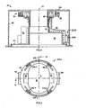
- FIGS.4-9 show a further embodiment of an inductive coupling device 230 equipping a charging device 10. Those details of the charging device 10 of FIGS.4-9 that correspond to those described in relation to FIG.1 are not repeated hereinafter.
- the inductive coupling device 230 of FIGS.4-9 is arranged in the lower part of the stationary housing 18 as best seen in FIG.8 . Similar to the coupling devices described hereinbefore, the inductive coupling device 230 comprises a stationary inductor 234 with a magnetic core arrangement 238 and a rotary inductor 236 with a magnetic core arrangement 240. The core arrangements 238, 240 and their coil windings are dimensioned for higher wattage power transmission when compared to the embodiment in FIG.1 . Since the coupling device 230 is in the lower part of the housing 18, rotary inductor 236 is supported directly on the platform 17, whereas the stationary inductor 234 is fixed to the wall of housing 18.
- both core arrangements 238, 240 are provided with respective coil windings.
- both the stationary and rotary inductors 234, 236 and their respective stationary and rotary magnetic core arrangements 238, 240 are discontinuous in the direction of rotation of the rotatable structure 16 (discontinuous circle configuration).
- the stationary inductor 234 is composed of two sectors 234.1, 234.2 whereas the rotary inductor 236 is composed of four sectors 236.1, 236.2, 236.3 & 236.4.
- the sectors 234.1, 234.2; 236.1, 236.2, 236.3 & 236.4 are arranged in rotationally symmetry with respect to axis A.
- Only the opposing faces of the stationary and rotary magnetic core arrangements 238, 240 need to be machined with high precision in order to achieve a circular horizontal section.
- the radial gap 32 is circular and centered onto axis A.
- respective apertures in the circumference of the magnetic core arrangements 238, 240 allow accessing internal parts on the rotatable structure 16, e.g. for maintenance interventions, without dismantling the inductive coupling device 230.
- access is given to both halves of the support and driving mechanism of the distribution chute 12, schematically shown at reference numbers 52, 54, but also to the cooling circuit 28 or its coolant pump (not shown) for example.
- both halves of the support and driving mechanism 52, 54 arranged on the support platform 17 can be accessed through access doors 56, 58 in the housing 18.
- FIG.9 shows an intermediate rotational position of the rotatable structure 16.
- a circumferentially interrupted coupling device 230 may also be used in view of constructional constraints.
- the height of the vertical portion of the substantially U-shaped parts of the magnetic core arrangements 238, 240 accommodates a large number of coil windings (not shown) for achieving considerable inductance, since inductance increases with the square of the winding number.
- the arrangement of FIGS.4-9 is appropriate for high power applications, e.g. loads requiring >10kW electric power supply.
- a given pole face portion of the stationary magnetic core arrangement 238 is not at all times opposed to a corresponding pole face portion of the rotary magnetic core arrangement 240 during a given cycle of rotation.
- the total coupling surface for magnetic coupling through the radial gap 32 remains constant during rotation of the rotary inductor 236, i.e. independent of the rotational position of the rotary inductor 236 relative to the stationary inductor 234.
- the term coupling surface is defined as that surface on which pole faces-(see 48, 50; 48', 50' in FIG.2 ) of the stationary core arrangement 238 are radially opposed to pole faces of the rotary core arrangement 240 and vice versa, i.e. the surface area through which effective magnetic coupling can be achieved. Consequently, in the embodiment of FIGS.4-9 , the total coupling surface is the sum of such separate surfaces given by the radian measure of the opposed portions (hatched in FIGS.5 , 7 & 9 ) of sectors 234.1, 234.2; 236.1, 236.2, 236.3 & 236.4, respectively multiplied by the summed vertical height of the corresponding pole faces (see 48, 50; 48', 50' in FIG.2 ).
- the coupled magnetic flux and hence electric power transferred to the rotatable structure 16 is also independent of rotational position of the latter, despite the discontinuous configuration of the stationary and rotary inductors 234, 236 according to FIGS.4-9 .
- an appropriate diameter of the inductive_coupling device 230 a degree of magnetic coupling similar to that of a continuous configuration of smaller diameter (e.g. according to FIG.1 ) can be achieved with the discontinuous configuration of the coupling device 230 of FIGS.4-9 .
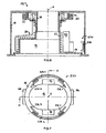
- FIGS.10-11 show a further embodiment of an inductive coupling device 330 equipping a charging device 10.
- the coupling device 330 has a discontinuous configuration. Only the differences with respect to the previously described embodiments will be detailed below.
- the inductive coupling device 330 is arranged at intermediate height within the housing 18. This location enables reducing the device diameter and hence material cost, approaching the roller bearings 20 such that the required width tolerance of the gap 32 is smaller, and reducing exposure to furnace dust and heat.
- the rotary inductor 336 of the inductive coupling device 330 is discontinuous in the direction of rotation whereas the stationary inductor 334 is configured as a full circle ring about axis A.
- the diameter of the coupling device 330 is slightly reduced compared to that of FIGS.4-9 .
- the rotary inductor 336 is composed of two distinct circular arc shaped sectors 336.1, 336.2.
- Sectors 336.1, 336.2 are separated by apertures only at the location of the two opposite halves of the support and driving mechanism 52, 54.
- the discontinuous rotary inductor 336 complies with constructional space constraints of the charging device 10 and facilitates access to the support and driving mechanism 52, 54.
- the inductive coupling device 330 allows contact-less electric energy transfer of even higher wattage compared to the previous embodiments. It will be understood that the specific electrical design of the schematically shown coupling device 230, 330 may correspond to that of FIG.2 , that of FIG.3 , or any other suitable electrical design readily appreciated by the skilled person.
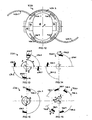
- FIG.12 shows a further embodiment of a coupling device 430 that can be considered as a variant of the embodiment illustrated in FIGS.4-9 .
- the coupling device 430 has a stationary inductor 434 that is configured as a full circle ring centered on axis A.
- the stationary inductor 434 has removable sectors 434.1, 434.3.
- the latter can for example be mounted on hinges to be pivotable relative to fixedly mounted sectors 434.2, 434.4 as indicated in FIG.12
- the hinged sector portions 434.1 and 434.3 are moved into a parking position shown in FIG 12 .
- the removable sector portions 434.1 and 434.3 are positioned (see broken lines in FIG. 12 to form a full circle ring together with the fixed sectors 434.2, 434.4. Since the magnetic flux direction in the magnetic core arrangements 438, 440 is perpendicular to the direction of rotation, an interruption of the magnetic core arrangement at the interfaces between removable sectors 434.1, 434.3 and fixed sectors 434.2, 434.4 is not critical.
- FIGS.13-19 illustrates an example of a discontinuous inductive coupling device enabling constant electric energy transfer irrespective of rotation of the rotatable structure 16.
- FIG.13 schematically illustrates the geometric configuration of the circumferentially interrupted, i.e. discontinuous circle coupling device 230 shown in FIGS.4-9 .
- both sectors 234.1, 234.2 of the stationary inductor 234 as well as the four sectors 236.1, 236.2, 236.3 & 236.4 of the rotary inductor 236 are arranged in rotational symmetry about axis A.
- the respective radian measures ⁇ of the stationary sectors 234.1, 234.2 are identical and approximately equal to ⁇ /2 or 90°.
- the two apertures in between the stationary sectors 234.1, 234.2 also have identical radian measure ⁇ approximately equal to ⁇ /2 or 90°.
- the radian measure ⁇ of the sectors 236.1, 236.2, 236.3 & 236.4 is a compromise value between desired electromagnetic coupling and access space, e.g. for maintenance.
- the value of ⁇ is in itself not critical for achieving constant inductive coupling.
- the respective radian measures, ⁇ , ⁇ , y determine the arc lengths of the apertures and the stationary 234.1, 234.2 and rotary sectors 236.1, 236.2, 236.3 & 236.4, whereby among others the total coupling surface can be determined.
- conjugated sectors shall be used to refer to a given pair of rotary sectors that satisfy the condition of being the circumferentially closest pair in which one sector is simultaneously causing an increase in coupling when its conjugate is causing a decrease in coupling and vice versa.
- the pairs (236.1, 236.2) and (236.3, 236.4) are pairs of conjugated sectors.
- the radian measure ⁇ in between the centers of two conjugated sectors, e.g. 236.1 and 236.2, is chosen in function of the radian measured of the aperture(s).
- ⁇ is a divisor of ⁇ , i.e.
- both conjugated sectors e.g. (236.1, 236.2) and (236.3, 236.4), shall have identical radian measure ⁇ and be arranged symmetrical with respect to the plane defined by their bisector used to define ⁇ . Thereby it is ensured that the total coupling surface is independent of the rotational position of the rotary inductor 236. In fact the above conditions make sure that when the coupling surface at a given sector, say 236.2, is reduced or increased due to rotation, the coupling surface at its conjugated sector, say 236.1, is simultaneously reduced or increased by the same amount.
- FIG.14 shows a coupling device 530 according to a variant of the embodiment of FIGS.4-9 & 13 in which the rotary inductor 536 comprises only one pair of conjugated rotary sectors 536.1 and 536.2.
- the rotary inductor 536 need not necessarily be rotationally symmetrical about axis A (considering 1-fold symmetry not to be a symmetry). In certain configurations, it is sufficient that either one of the stationary or the rotary inductor 534, 536 has rotational symmetry, as illustrated also by FIG.15 .
- FIG.15 shows a further example of a coupling device 630 having a single pair of rotary sectors 636.1 and 636.2 and only one stationary sector 634.1.
- the stationary and rotary inductors 734, 736 respectively have four sectors 734.1, 734.2, 734.3 & 734.4 and 736.1, 736.2, 736.3 & 736.4.
- the radian measure ⁇ of the rotary sectors 736.1, 736.2, 736.3 & 736.4 may be increased or reduced without affecting the fact that electromagnetic coupling is independent of rotation.
- the radian measure ⁇ i.e. arch length, of both sectors shall be identical and satisfy ⁇ ⁇ ⁇ .
- the stationary inductor 834 comprises three separate sectors 834.1, 834.2 & 834.3, whereas the rotary inductor 836 comprises four distinct rotary sectors 836.1, 836.2, 836.3 & 836.4.
- the sectors are arranged in rotational symmetry about axis A.
- the conjugated rotary sectors in the coupling device 830 are those that are radially opposed, i.e. sectors (836.1, 836.3) and (836.2, 836.4) are respectively conjugated.
- ⁇ > ⁇ whereas in the preceding embodiments ⁇ ⁇ ⁇ .
- FIG.18 shows a coupling device 930, which is a variant of the embodiment of FIG.17 in that it has only one pair of conjugated sectors 936.1, 936.2 in the rotary inductor 936. It appears from the comparison of FIGS.17 &18 that the actual number of conjugated pairs that are used is not decisive as long as the conditions for rotation-independent coupling remain satisfied. For example, a further conjugated pair (not shown) could be added to the coupling device 830 of FIG.17 by interposing two radially opposite sectors at 45° in between the sector pairs (836.1, 836.2) and (836.3, 836.4) without affecting rotational independence.
- FIG.19 shows a further embodiment of a coupling device 1030.
- electric energy transfer from the stationary inductor 1034 to the rotary inductor 1036 by means of magnetic coupling trough the radial gap 32 is also substantially constant during rotation of the rotary inductor 1036.
- FIG.20 using phasor notation:
- the inductive coupling device basically resembles that of a rotary transformer. Therefore, Xmu is an important parameter as regards the design of the inductive coupling device.
- Xmu 2 ⁇ ⁇ ⁇ f ⁇ n 1 2 R core + R gap , with f being the AC frequency, n 1 being the number of turns at the stationary inductor winding and core , gap being the core reluctance and the reluctance of the radial gap 32 respectively. Since the permeability of the core material is several thousand times larger than that of the radial gap 32, core is negligible compared to gap in equation (1). Because reluctance of the radial gap 32 is directly proportional to the width (i.e.
- this width should be minimized in order to warrant a high mutual inductance Xmu.
- rendering R1, R2 and the X1, X2 as small as possible are measures for optimizing inductive coupling efficiency.
- the interferric width e of the radial gap 32 will generally be in the order of 0mm ⁇ e ⁇ 2mm. Effective efficiency values above 70% are achievable at the expense of using larger winding wire cross-sections, using higher permeability core materials (e.g. PERMALLOY), enabling a smaller interferric width e and/or various other measures readily appreciated by the skilled person.
- any supplementary components can be used in combination with the inductive coupling device where necessary.
- the coupling device may be supplemented with energy storage and a rectifier or with an electric power controller. It will be appreciated that no electrical means beyond the electromechanical design disclosed herein are required to achieve substantially constant power supply to a load arranged on the rotatable structure 16.
- the inductive coupling device could theoretically be used for combined signal and power transmission, it is considered preferable to use radio equipment for signal transmission.
- a radio transmitter, receiver or transceiver can be arranged on the rotatable structure 16 for receiving and/or transmitting control and/or measurement signals from or to the load connected to the rotary inductor. Both the load and the radio equipment can be powered via the coupling device.
- a shaft furnace charging device upgraded with an inductive coupling device descried hereinbefore is ready to receive any type of electric load arranged on the rotatable structure. Due to the high power capacity of the coupling device, one or more loads having nominal power consumption well above 500W can be conveniently and reliably operated on the rotating part of the charging device, irrespective of the operating conditions. By virtue of its contact-less design, the inductive coupling device will-not suffer from wear and it is therefore virtually maintenance free despite the harsh operating conditions of a shaft furnace.
Landscapes
- Engineering & Computer Science (AREA)
- Chemical & Material Sciences (AREA)
- Mechanical Engineering (AREA)
- General Engineering & Computer Science (AREA)
- Manufacturing & Machinery (AREA)
- Materials Engineering (AREA)
- Metallurgy (AREA)
- Organic Chemistry (AREA)
- Charge And Discharge Circuits For Batteries Or The Like (AREA)
- General Induction Heating (AREA)
- Vertical, Hearth, Or Arc Furnaces (AREA)
- Sheets, Magazines, And Separation Thereof (AREA)
- Crushing And Grinding (AREA)
- Arrangements For Transmission Of Measured Signals (AREA)
- Waveguide Connection Structure (AREA)
- Dynamo-Electric Clutches, Dynamo-Electric Brakes (AREA)
- Blast Furnaces (AREA)
Claims (15)
- Drehbare Beschickungsvorrichtung (10) für einen Schachtofen, umfassend:ein drehbares Verteilermittel (12) zum Verteilen von Einsatzmaterial auf einer Beschickungsfläche im Schachtofen;eine drehbare Struktur (16), welche das drehbare Verteilermittel trägt; undeinen feststehenden Träger (18), welcher die drehbare Struktur trägt;eine an der drehbaren Struktur angeordnete elektrische Last (M);
gekennzeichnet durch eine induktive Kopplungsvorrichtung (30; 130; 230; ... 1030) vom Typ Drehtransformator, umfassend:
einen am feststehenden Träger befestigten feststehenden Induktor (34; 134; 234; ... 1034) und einen an der drehbaren Struktur befestigten und an die elektrische Last angeschlossenen drehbaren Induktor (36; 136; 236; ... 1036),
wobei der feststehende Induktor und der drehbare Induktor durch einen Radialspalt (32) getrennt sind und für die Erzielung einer kontaktlosen Übertragung elektrischer Energie mittels eines Magnetfelds konfiguriert sind, das zur Speisung der elektrischen Last durch den Radialspalt hindurch gekoppelt ist. - Beschickungsvorrichtung nach Anspruch 1, wobei der feststehende Induktor eine feststehende Magnetkernanordnung (38; 138; 238; 338) umfasst und der drehbare Induktor eine drehbare Magnetkernanordnung (40; 140; 240; 340) umfasst.
- Beschickungsvorrichtung nach Anspruch 2, wobei der Radialspalt (32) mindestens eine Magnetpolfläche (48, 48') der feststehenden Kernanordnung derart von mindestens einer Magnetpolfläche (50, 50') der drehbaren Kernanordnung trennt, dass die feststehende Magnetpolfläche und die drehbare Magnetpolfläche in radial gegenüberliegender Beziehung angeordnet sind.
- Beschickungsvorrichtung nach Anspruch 1, 2 oder 3, wobei der Radialspalt (32) im Wesentlichen vertikal ist.
- Beschickungsvorrichtung nach irgendeinem der Ansprüche 1 bis 4, wobei der feststehende Induktor (234; 534; 634; 734; 834; 934; 1034) und/oder der drehbare Induktor (236; 336; 436; 536; 636; 736; 836; 936; 1036) in der Drehrichtung unterbrochen sind.
- Beschickungsvorrichtung nach Anspruch 5, wobei der feststehende Induktor (234; 334; 434; 534; 634; 734; 834; 934; 1034) und der drehbare Induktor (236; 336; 436; 536; 636; 736; 836; 936; 1036) derart konfiguriert sind, dass die gesamte Kopplungsfläche für die magnetische Kopplung zwischen dem feststehenden Induktor und dem drehbaren Induktor während der Drehung der drehbaren Struktur (16) gleichmäßig ist.
- Beschickungsvorrichtung nach Anspruch 6, wobei mindestens einer von dem feststehenden Induktor (234; 334; 434; 534; 734; 834; 934) und dem drehbaren Induktor (236; 336; 436; 636; 736; 836; 936; 1036) eine Geometrie aufweist, die rotationssymmetrisch zur Drehachse der drehbaren Struktur ist.
- Beschickungsvorrichtung nach Anspruch 7, wobei der feststehende Induktor (234; 334; 434; 534; 634; 734; 834; 934; 1034) mindestens eine Öffnung in seinem Umfang aufweist, durch welche er unterbrochen ist, wobei die Öffnung ein Bogenmaß β aufweist und wobei der drehbare Induktor mindestens ein Paar separater Sektoren (236.1-236.2, 236.3-236.4; 336.1-336.2; 436.1-436.2, 436.3-436.4; 536.1-536.2; 636.1-636.2; 736.1-736.2, 736.3-736.4; 836.1-836.2, 836.3-836.4; 936.1-936.2; 1036.1-1036.2, 1036.3-1036.4) umfasst, die derart angeordnet sind, dass das Bogenmaß δ zwischen den Halbierenden eines Paars derart beschaffen ist, dass δ ein Divisor von β ist oder dass β ein Divisor von δ ist.
- Beschickungsvorrichtung nach irgendeinem der Ansprüche 1 bis 8, wobei der feststehende Induktor (34; 134; 234; ... 1034) und der drehbare Induktor (36; 136; 236; ... 1036) jeweils mindestens eine Induktorwicklung umfassen, wobei jede Wicklung eine Windungszahl n im Bereich von 50 ≤ n ≤ 500 aufweist.
- Beschickungsvorrichtung nach irgendeinem der Ansprüche 1 bis 9, ferner umfassend einer Verteilerschurre (12), die einen Teil des drehbaren Verteilermittels bildet, und einen Elektromotor (M), der der Verteilerschurre wirksam zugeordnet ist, um den Neigungswinkel der Verteilerschurre zu verändern, wobei der Elektromotor als eine Last an den drehbaren Induktor (36; 136; 236; ... 1036) angeschlossen ist, um über die induktive Kopplungsvorrichtung gespeist zu werden.
- Beschickungsvorrichtung nach irgendeinem der Ansprüche 1 bis 9, ferner umfassend einer Verteilerschurre, die einen Teil des drehbaren Verteilermittels bildet, und einen Elektromotor, der der Verteilerschurre wirksam zugeordnet ist, um die Verteilerschurre um deren Längsachse zu drehen, wobei der Elektromotor als eine Last an den drehbaren Induktor (36; 136; 236; ... 1036) angeschlossen ist, um über die induktive Kopplungsvorrichtung gespeist zu werden.
- Beschickungsvorrichtung nach irgendeinem der vorangehenden Ansprüche, ferner umfassend einen Kühlkreislauf (28), der eine auf der drehbaren Struktur angeordnete Pumpe umfasst, wobei die Pumpe als eine Last an den drehbaren Induktor (36; 136; 236; ... 1036) angeschlossen ist, um über die induktive Kopplungsvorrichtung gespeist zu werden.
- Beschickungsvorrichtung nach irgendeinem der vorangehenden Ansprüche, wobei die elektrische Last eine Nennleistungsaufnahme ≥ 500 W aufweist.
- Beschickungsvorrichtung nach irgendeinem der Ansprüche 10 bis 13, ferner umfassend einen Funksender, -empfänger oder -sendeempfänger, der für das Empfangen und/oder Senden von Steuer- und/oder Messsignalen von bzw. zu der Last an der drehbaren Struktur angeordnet ist.
- Verfahren zum Aufrüsten einer drehbaren Beschickungsvorrichtung für einen Schachtofen, wobei die Beschickungsvorrichtung umfasst:ein drehbares Verteilermittel zum Verteilen von Einsatzmaterial auf einer Beschickungsfläche im Schachtofen,eine drehbare Struktur, welche das drehbare Verteilermittel trägt, undeinen feststehenden Träger, welcher die drehbare Struktur trägt;eine an der drehbaren Struktur angeordnete elektrische Last;
gekennzeichnet durchBereitstellen einer induktiven Kopplungsvorrichtung vom Typ Drehtransformator, die einen feststehenden Induktor und einen drehbaren Induktor umfasst,Befestigen des feststehenden Induktors am feststehenden Träger undBefestigen des drehbaren Induktors an der drehbaren Struktur undAnschließen des drehbaren Induktors an die elektrische Last, derart, dass der feststehende Induktor und der drehbare Induktor durch einen Radialspalt getrennt sind und für die Ausführung einer kontaktlosen Übertragung elektrischer Energie vom feststehenden Träger zur drehbaren Struktur mittels eines Magnetfelds konfiguriert sind, das zur Speisung der elektrischen Last durch den Radialspalt hindurch gekoppelt ist.
Priority Applications (1)
| Application Number | Priority Date | Filing Date | Title |
|---|---|---|---|
| EP07847379A EP2094875B1 (de) | 2006-12-18 | 2007-11-27 | Rotationsbeschickungsvorrichtung für einen schachtofen und verfahren zur aktualisierung solcher vorrichtung |
Applications Claiming Priority (3)
| Application Number | Priority Date | Filing Date | Title |
|---|---|---|---|
| EP06126393A EP1935993A1 (de) | 2006-12-18 | 2006-12-18 | Ein Drehbeschickungsgerät für einen Schachtofen |
| PCT/EP2007/062852 WO2008074596A1 (en) | 2006-12-18 | 2007-11-27 | A rotary charging device for a shaft furnace |
| EP07847379A EP2094875B1 (de) | 2006-12-18 | 2007-11-27 | Rotationsbeschickungsvorrichtung für einen schachtofen und verfahren zur aktualisierung solcher vorrichtung |
Publications (2)
| Publication Number | Publication Date |
|---|---|
| EP2094875A1 EP2094875A1 (de) | 2009-09-02 |
| EP2094875B1 true EP2094875B1 (de) | 2010-12-08 |
Family
ID=38051822
Family Applications (2)
| Application Number | Title | Priority Date | Filing Date |
|---|---|---|---|
| EP06126393A Withdrawn EP1935993A1 (de) | 2006-12-18 | 2006-12-18 | Ein Drehbeschickungsgerät für einen Schachtofen |
| EP07847379A Active EP2094875B1 (de) | 2006-12-18 | 2007-11-27 | Rotationsbeschickungsvorrichtung für einen schachtofen und verfahren zur aktualisierung solcher vorrichtung |
Family Applications Before (1)
| Application Number | Title | Priority Date | Filing Date |
|---|---|---|---|
| EP06126393A Withdrawn EP1935993A1 (de) | 2006-12-18 | 2006-12-18 | Ein Drehbeschickungsgerät für einen Schachtofen |
Country Status (12)
| Country | Link |
|---|---|
| US (1) | US8088327B2 (de) |
| EP (2) | EP1935993A1 (de) |
| KR (1) | KR101394334B1 (de) |
| CN (2) | CN101563468B (de) |
| AT (1) | ATE491047T1 (de) |
| BR (1) | BRPI0721057A2 (de) |
| CA (1) | CA2671393C (de) |
| DE (1) | DE602007011109D1 (de) |
| EA (1) | EA013939B1 (de) |
| TW (1) | TWI419977B (de) |
| UA (1) | UA93935C2 (de) |
| WO (1) | WO2008074596A1 (de) |
Families Citing this family (7)
| Publication number | Priority date | Publication date | Assignee | Title |
|---|---|---|---|---|
| LU91480B1 (en) * | 2008-09-12 | 2010-03-15 | Wurth Paul Sa | Shaft furnace charging device and corresponding distribution chute |
| LU91583B1 (en) * | 2009-07-03 | 2011-01-04 | Wurth Paul Sa | Sealing valve arrangement for a shaft furnace charging installation |
| LU91601B1 (en) * | 2009-08-26 | 2012-09-13 | Wurth Paul Sa | Shaft furnace charging device equipped with a cooling system and annular swivel joint therefore |
| LU92045B1 (en) | 2012-07-18 | 2014-01-20 | Wurth Paul Sa | Rotary charging device for shaft furnace |
| LU92046B1 (en) * | 2012-07-18 | 2014-01-20 | Wurth Paul Sa | Rotary charging device for shaft furnace |
| FI124217B (en) | 2012-08-27 | 2014-05-15 | Outotec Oyj | ARRANGEMENTS FOR SUPPLYING A GRINDING SUBSTANCE TO A SUSPENSION FROZEN OVEN OR A STONE BURNER |
| LU92469B1 (en) * | 2014-06-06 | 2015-12-07 | Wurth Paul Sa | Gearbox assembly for a charging installation of a metallurgical reactor |
Family Cites Families (19)
| Publication number | Priority date | Publication date | Assignee | Title |
|---|---|---|---|---|
| LU59207A1 (de) | 1969-07-31 | 1969-12-10 | Wurth Anciens Ets Paul | |
| US3732487A (en) * | 1971-08-12 | 1973-05-08 | Magnetech Ind Inc | Method and apparatus for electrically coupling an output voltage from a variable induction device to load |
| LU65537A1 (de) | 1972-06-16 | 1972-10-25 | ||
| EP0050314A3 (de) * | 1980-10-20 | 1983-10-19 | Georg Ignatius | Schwingkörper, insbesondere Resonanzkörper für Klangerzeugungsgeräte |
| LU84520A1 (fr) * | 1982-12-10 | 1984-10-22 | Wurth Paul Sa | Dispositif de refroidissement d'une installation de chargement d'un four a cuve |
| CS236410B1 (cs) * | 1983-12-20 | 1986-06-01 | Miroslav Babinec | Elektromagnetický pohon sazebny šachtové pece a ji podobných agregátů |
| CS236536B1 (cs) * | 1983-12-20 | 1986-11-15 | Miroslav Babinec | Elektromagnetický pohon ukládacího žlabu sazebny šachtové pece a ji podobných agregátů |
| CS236408B1 (cs) * | 1983-12-20 | 1986-06-01 | Miroslav Babinec | Elektromagnetický pohon ukládaoího žlabu sazebny šachtové pece a jí podobných agregátů |
| US4598325A (en) * | 1985-05-29 | 1986-07-01 | Rca Corporation | Apparatus for transmitting digital signals across a rotary gap |
| LU87948A1 (fr) | 1991-06-12 | 1993-01-15 | Wurth Paul Sa | Dispositif de refroidissement d'une goulotte de distribution d'une installation de chargement d'un four a cuve |
| DE19709329C2 (de) * | 1997-03-07 | 2001-03-08 | Sms Demag Ag | Glockenloser Gichtverschluß für Schachtöfen, insbesondere Hochöfen |
| LU90179B1 (fr) * | 1997-11-26 | 1999-05-27 | Wurth Paul Sa | Procede pour refroidir un dispositif de chargement d'un four a cuve |
| LU90294B1 (fr) | 1998-10-06 | 2000-04-07 | Wurth Paul Sa | Dispositif de répartition de matières en vrac |
| LU90794B1 (fr) * | 2001-06-26 | 2002-12-27 | Wurth Paul Sa | Dispositif de chargement d'un four à cuve |
| LU90863B1 (en) | 2001-12-13 | 2003-06-16 | Wurth Paul Sa | Charging device with rotary chute |
| DE10334417A1 (de) * | 2003-06-20 | 2005-01-05 | Z & J Technologies Gmbh | Ofenkopf bzw. Gichtverschluß |
| KR100985372B1 (ko) * | 2003-07-09 | 2010-10-04 | 주식회사 포스코 | 용광로 장입 분배슈트의 구동장치 |
| US7267266B2 (en) * | 2003-07-10 | 2007-09-11 | Rouille David W | Security system |
| LU91217B1 (fr) * | 2006-01-20 | 2007-07-23 | Wurth Paul Sa | Dispositif de chargement d'un four à cuve |
-
2006
- 2006-12-18 EP EP06126393A patent/EP1935993A1/de not_active Withdrawn
-
2007
- 2007-11-27 DE DE602007011109T patent/DE602007011109D1/de active Active
- 2007-11-27 CA CA2671393A patent/CA2671393C/en not_active Expired - Fee Related
- 2007-11-27 US US12/520,038 patent/US8088327B2/en not_active Expired - Fee Related
- 2007-11-27 AT AT07847379T patent/ATE491047T1/de active
- 2007-11-27 WO PCT/EP2007/062852 patent/WO2008074596A1/en not_active Ceased
- 2007-11-27 BR BRPI0721057-4A patent/BRPI0721057A2/pt not_active Application Discontinuation
- 2007-11-27 KR KR1020097012263A patent/KR101394334B1/ko not_active Expired - Fee Related
- 2007-11-27 CN CN2007800466654A patent/CN101563468B/zh active Active
- 2007-11-27 EP EP07847379A patent/EP2094875B1/de active Active
- 2007-11-27 UA UAA200907280A patent/UA93935C2/ru unknown
- 2007-11-27 EA EA200900813A patent/EA013939B1/ru not_active IP Right Cessation
- 2007-12-11 CN CNU2007203106018U patent/CN201215437Y/zh not_active Expired - Lifetime
- 2007-12-18 TW TW096148344A patent/TWI419977B/zh not_active IP Right Cessation
Also Published As
| Publication number | Publication date |
|---|---|
| KR20090100351A (ko) | 2009-09-23 |
| TWI419977B (zh) | 2013-12-21 |
| EA200900813A1 (ru) | 2009-12-30 |
| TW200839016A (en) | 2008-10-01 |
| CA2671393C (en) | 2014-06-17 |
| EP2094875A1 (de) | 2009-09-02 |
| ATE491047T1 (de) | 2010-12-15 |
| EA013939B1 (ru) | 2010-08-30 |
| KR101394334B1 (ko) | 2014-05-13 |
| CA2671393A1 (en) | 2008-06-26 |
| CN101563468B (zh) | 2012-09-05 |
| DE602007011109D1 (de) | 2011-01-20 |
| US20100028106A1 (en) | 2010-02-04 |
| EP1935993A1 (de) | 2008-06-25 |
| CN201215437Y (zh) | 2009-04-01 |
| CN101563468A (zh) | 2009-10-21 |
| BRPI0721057A2 (pt) | 2014-02-25 |
| UA93935C2 (ru) | 2011-03-25 |
| WO2008074596A1 (en) | 2008-06-26 |
| US8088327B2 (en) | 2012-01-03 |
Similar Documents
| Publication | Publication Date | Title |
|---|---|---|
| EP2094875B1 (de) | Rotationsbeschickungsvorrichtung für einen schachtofen und verfahren zur aktualisierung solcher vorrichtung | |
| JP3439705B2 (ja) | 加熱ロール用誘導加熱装置 | |
| US20150290703A1 (en) | Stirring-roll for a continuous cast machine of metallic products of large cross section | |
| US12421564B2 (en) | Iron (DRI) between a DRI source and processing equipment for the DRI | |
| US11846001B2 (en) | Split multiple coil electric induction heat treatment systems for simultaneous heating of multiple features of a bearing component | |
| KR20200111167A (ko) | 가열 장치 및 대응하는 기기 및 방법 | |
| US20150211793A1 (en) | Rotary charging device for shaft furnace | |
| AU659366B1 (en) | Method of preventing generation of earth circulating current in induction heating apparatus for molten steel | |
| CA1107336A (en) | Shaft furnace for producing low-oxygen iron-base metallic powder for powder metallurgy | |
| EP2366474B1 (de) | Vorrichtung zur erfassung des schlackengehalts in einem flüssigmetallstrom | |
| CN210242369U (zh) | 一种电磁搅拌电炉 | |
| EP0657236B1 (de) | Giesspfanne mit einem Induktionsheizgerät, für Metallschmelze | |
| US5987054A (en) | Induction coil and coreless induction furnace employing same | |
| CN104004981B (zh) | 一种冷轧钛带卷真空感应直接加热退火装置 | |
| US4276082A (en) | Process for the heating and/or melting of metals and an induction furnace to carry out the process | |
| SU1300284A2 (ru) | Отъемна индукционна единица | |
| US1751912A (en) | Electric induction furnace | |
| CN102091763B (zh) | 一种用于制备非晶带材的连续给料装置 | |
| CN211360639U (zh) | 一种双流感应加热中间包装置 | |
| CN201945173U (zh) | 一种感应线圈匝间绝缘用石棉垫 | |
| JP3025354B2 (ja) | 金属塊の空中浮揚加熱方法及びその装置 | |
| JP2014189894A (ja) | 還元鉄の誘導加熱方法及び還元鉄の誘導加熱装置 | |
| CN118589727A (zh) | 一种磁悬浮电机及风机 | |
| CN121323343A (zh) | 集成防渣堵功能的中频感应浇注炉 | |
| HU203009B (en) | Induction melting unit of plasma arc |
Legal Events
| Date | Code | Title | Description |
|---|---|---|---|
| PUAI | Public reference made under article 153(3) epc to a published international application that has entered the european phase |
Free format text: ORIGINAL CODE: 0009012 |
|
| 17P | Request for examination filed |
Effective date: 20090527 |
|
| AK | Designated contracting states |
Kind code of ref document: A1 Designated state(s): AT BE BG CH CY CZ DE DK EE ES FI FR GB GR HU IE IS IT LI LT LU LV MC MT NL PL PT RO SE SI SK TR |
|
| RTI1 | Title (correction) |
Free format text: A ROTARY CHARGING DEVICE FOR A SHAFT FURNACE AND METHOD FOR UPGRADING SUCH A DEVICE |
|
| DAX | Request for extension of the european patent (deleted) | ||
| GRAC | Information related to communication of intention to grant a patent modified |
Free format text: ORIGINAL CODE: EPIDOSCIGR1 |
|
| GRAP | Despatch of communication of intention to grant a patent |
Free format text: ORIGINAL CODE: EPIDOSNIGR1 |
|
| GRAS | Grant fee paid |
Free format text: ORIGINAL CODE: EPIDOSNIGR3 |
|
| GRAA | (expected) grant |
Free format text: ORIGINAL CODE: 0009210 |
|
| AK | Designated contracting states |
Kind code of ref document: B1 Designated state(s): AT BE BG CH CY CZ DE DK EE ES FI FR GB GR HU IE IS IT LI LT LU LV MC MT NL PL PT RO SE SI SK TR |
|
| REG | Reference to a national code |
Ref country code: GB Ref legal event code: FG4D |
|
| REG | Reference to a national code |
Ref country code: CH Ref legal event code: EP |
|
| REG | Reference to a national code |
Ref country code: IE Ref legal event code: FG4D |
|
| REF | Corresponds to: |
Ref document number: 602007011109 Country of ref document: DE Date of ref document: 20110120 Kind code of ref document: P |
|
| REG | Reference to a national code |
Ref country code: NL Ref legal event code: VDEP Effective date: 20101208 |
|
| PG25 | Lapsed in a contracting state [announced via postgrant information from national office to epo] |
Ref country code: LT Free format text: LAPSE BECAUSE OF FAILURE TO SUBMIT A TRANSLATION OF THE DESCRIPTION OR TO PAY THE FEE WITHIN THE PRESCRIBED TIME-LIMIT Effective date: 20101208 |
|
| LTIE | Lt: invalidation of european patent or patent extension |
Effective date: 20101208 |
|
| PG25 | Lapsed in a contracting state [announced via postgrant information from national office to epo] |
Ref country code: LV Free format text: LAPSE BECAUSE OF FAILURE TO SUBMIT A TRANSLATION OF THE DESCRIPTION OR TO PAY THE FEE WITHIN THE PRESCRIBED TIME-LIMIT Effective date: 20101208 Ref country code: FI Free format text: LAPSE BECAUSE OF FAILURE TO SUBMIT A TRANSLATION OF THE DESCRIPTION OR TO PAY THE FEE WITHIN THE PRESCRIBED TIME-LIMIT Effective date: 20101208 Ref country code: SI Free format text: LAPSE BECAUSE OF FAILURE TO SUBMIT A TRANSLATION OF THE DESCRIPTION OR TO PAY THE FEE WITHIN THE PRESCRIBED TIME-LIMIT Effective date: 20101208 Ref country code: NL Free format text: LAPSE BECAUSE OF FAILURE TO SUBMIT A TRANSLATION OF THE DESCRIPTION OR TO PAY THE FEE WITHIN THE PRESCRIBED TIME-LIMIT Effective date: 20101208 Ref country code: SE Free format text: LAPSE BECAUSE OF FAILURE TO SUBMIT A TRANSLATION OF THE DESCRIPTION OR TO PAY THE FEE WITHIN THE PRESCRIBED TIME-LIMIT Effective date: 20101208 Ref country code: BG Free format text: LAPSE BECAUSE OF FAILURE TO SUBMIT A TRANSLATION OF THE DESCRIPTION OR TO PAY THE FEE WITHIN THE PRESCRIBED TIME-LIMIT Effective date: 20110308 Ref country code: CY Free format text: LAPSE BECAUSE OF FAILURE TO SUBMIT A TRANSLATION OF THE DESCRIPTION OR TO PAY THE FEE WITHIN THE PRESCRIBED TIME-LIMIT Effective date: 20101208 |
|
| PG25 | Lapsed in a contracting state [announced via postgrant information from national office to epo] |
Ref country code: GR Free format text: LAPSE BECAUSE OF FAILURE TO SUBMIT A TRANSLATION OF THE DESCRIPTION OR TO PAY THE FEE WITHIN THE PRESCRIBED TIME-LIMIT Effective date: 20110309 Ref country code: BE Free format text: LAPSE BECAUSE OF FAILURE TO SUBMIT A TRANSLATION OF THE DESCRIPTION OR TO PAY THE FEE WITHIN THE PRESCRIBED TIME-LIMIT Effective date: 20101208 Ref country code: EE Free format text: LAPSE BECAUSE OF FAILURE TO SUBMIT A TRANSLATION OF THE DESCRIPTION OR TO PAY THE FEE WITHIN THE PRESCRIBED TIME-LIMIT Effective date: 20101208 Ref country code: PT Free format text: LAPSE BECAUSE OF FAILURE TO SUBMIT A TRANSLATION OF THE DESCRIPTION OR TO PAY THE FEE WITHIN THE PRESCRIBED TIME-LIMIT Effective date: 20110408 Ref country code: ES Free format text: LAPSE BECAUSE OF FAILURE TO SUBMIT A TRANSLATION OF THE DESCRIPTION OR TO PAY THE FEE WITHIN THE PRESCRIBED TIME-LIMIT Effective date: 20110319 Ref country code: IS Free format text: LAPSE BECAUSE OF FAILURE TO SUBMIT A TRANSLATION OF THE DESCRIPTION OR TO PAY THE FEE WITHIN THE PRESCRIBED TIME-LIMIT Effective date: 20110408 |
|
| PG25 | Lapsed in a contracting state [announced via postgrant information from national office to epo] |
Ref country code: PL Free format text: LAPSE BECAUSE OF FAILURE TO SUBMIT A TRANSLATION OF THE DESCRIPTION OR TO PAY THE FEE WITHIN THE PRESCRIBED TIME-LIMIT Effective date: 20101208 Ref country code: RO Free format text: LAPSE BECAUSE OF FAILURE TO SUBMIT A TRANSLATION OF THE DESCRIPTION OR TO PAY THE FEE WITHIN THE PRESCRIBED TIME-LIMIT Effective date: 20101208 Ref country code: SK Free format text: LAPSE BECAUSE OF FAILURE TO SUBMIT A TRANSLATION OF THE DESCRIPTION OR TO PAY THE FEE WITHIN THE PRESCRIBED TIME-LIMIT Effective date: 20101208 |
|
| PLBE | No opposition filed within time limit |
Free format text: ORIGINAL CODE: 0009261 |
|
| STAA | Information on the status of an ep patent application or granted ep patent |
Free format text: STATUS: NO OPPOSITION FILED WITHIN TIME LIMIT |
|
| PG25 | Lapsed in a contracting state [announced via postgrant information from national office to epo] |
Ref country code: DK Free format text: LAPSE BECAUSE OF FAILURE TO SUBMIT A TRANSLATION OF THE DESCRIPTION OR TO PAY THE FEE WITHIN THE PRESCRIBED TIME-LIMIT Effective date: 20101208 |
|
| 26N | No opposition filed |
Effective date: 20110909 |
|
| REG | Reference to a national code |
Ref country code: DE Ref legal event code: R097 Ref document number: 602007011109 Country of ref document: DE Effective date: 20110909 |
|
| PGFP | Annual fee paid to national office [announced via postgrant information from national office to epo] |
Ref country code: FR Payment date: 20111021 Year of fee payment: 5 |
|
| PG25 | Lapsed in a contracting state [announced via postgrant information from national office to epo] |
Ref country code: MC Free format text: LAPSE BECAUSE OF NON-PAYMENT OF DUE FEES Effective date: 20111130 |
|
| REG | Reference to a national code |
Ref country code: CH Ref legal event code: PL |
|
| PG25 | Lapsed in a contracting state [announced via postgrant information from national office to epo] |
Ref country code: LI Free format text: LAPSE BECAUSE OF NON-PAYMENT OF DUE FEES Effective date: 20111130 Ref country code: CH Free format text: LAPSE BECAUSE OF NON-PAYMENT OF DUE FEES Effective date: 20111130 |
|
| REG | Reference to a national code |
Ref country code: IE Ref legal event code: MM4A |
|
| PG25 | Lapsed in a contracting state [announced via postgrant information from national office to epo] |
Ref country code: IE Free format text: LAPSE BECAUSE OF NON-PAYMENT OF DUE FEES Effective date: 20111127 |
|
| PG25 | Lapsed in a contracting state [announced via postgrant information from national office to epo] |
Ref country code: MT Free format text: LAPSE BECAUSE OF FAILURE TO SUBMIT A TRANSLATION OF THE DESCRIPTION OR TO PAY THE FEE WITHIN THE PRESCRIBED TIME-LIMIT Effective date: 20101208 |
|
| PG25 | Lapsed in a contracting state [announced via postgrant information from national office to epo] |
Ref country code: LU Free format text: LAPSE BECAUSE OF NON-PAYMENT OF DUE FEES Effective date: 20111127 |
|
| REG | Reference to a national code |
Ref country code: FR Ref legal event code: ST Effective date: 20130731 |
|
| PG25 | Lapsed in a contracting state [announced via postgrant information from national office to epo] |
Ref country code: IT Free format text: LAPSE BECAUSE OF NON-PAYMENT OF DUE FEES Effective date: 20121127 |
|
| PG25 | Lapsed in a contracting state [announced via postgrant information from national office to epo] |
Ref country code: HU Free format text: LAPSE BECAUSE OF FAILURE TO SUBMIT A TRANSLATION OF THE DESCRIPTION OR TO PAY THE FEE WITHIN THE PRESCRIBED TIME-LIMIT Effective date: 20101208 |
|
| PG25 | Lapsed in a contracting state [announced via postgrant information from national office to epo] |
Ref country code: FR Free format text: LAPSE BECAUSE OF NON-PAYMENT OF DUE FEES Effective date: 20121130 |
|
| PGFP | Annual fee paid to national office [announced via postgrant information from national office to epo] |
Ref country code: CZ Payment date: 20141106 Year of fee payment: 8 Ref country code: GB Payment date: 20141014 Year of fee payment: 8 |
|
| GBPC | Gb: european patent ceased through non-payment of renewal fee |
Effective date: 20151127 |
|
| PG25 | Lapsed in a contracting state [announced via postgrant information from national office to epo] |
Ref country code: CZ Free format text: LAPSE BECAUSE OF NON-PAYMENT OF DUE FEES Effective date: 20151127 |
|
| PG25 | Lapsed in a contracting state [announced via postgrant information from national office to epo] |
Ref country code: GB Free format text: LAPSE BECAUSE OF NON-PAYMENT OF DUE FEES Effective date: 20151127 |
|
| PGFP | Annual fee paid to national office [announced via postgrant information from national office to epo] |
Ref country code: TR Payment date: 20161108 Year of fee payment: 10 |
|
| PGFP | Annual fee paid to national office [announced via postgrant information from national office to epo] |
Ref country code: NL Payment date: 20181213 Year of fee payment: 12 |
|
| REG | Reference to a national code |
Ref country code: AT Ref legal event code: MM01 Ref document number: 491047 Country of ref document: AT Kind code of ref document: T Effective date: 20191127 |
|
| PG25 | Lapsed in a contracting state [announced via postgrant information from national office to epo] |
Ref country code: AT Free format text: LAPSE BECAUSE OF NON-PAYMENT OF DUE FEES Effective date: 20191127 |
|
| PG25 | Lapsed in a contracting state [announced via postgrant information from national office to epo] |
Ref country code: TR Free format text: LAPSE BECAUSE OF NON-PAYMENT OF DUE FEES Effective date: 20171127 |
|
| P01 | Opt-out of the competence of the unified patent court (upc) registered |
Effective date: 20230524 |
|
| PGFP | Annual fee paid to national office [announced via postgrant information from national office to epo] |
Ref country code: DE Payment date: 20241015 Year of fee payment: 18 |