EP2094530B1 - A service vehicle illumination system, use of such a system and a module system - Google Patents
A service vehicle illumination system, use of such a system and a module system Download PDFInfo
- Publication number
- EP2094530B1 EP2094530B1 EP07857721A EP07857721A EP2094530B1 EP 2094530 B1 EP2094530 B1 EP 2094530B1 EP 07857721 A EP07857721 A EP 07857721A EP 07857721 A EP07857721 A EP 07857721A EP 2094530 B1 EP2094530 B1 EP 2094530B1
- Authority
- EP
- European Patent Office
- Prior art keywords
- service vehicle
- illumination system
- vehicle illumination
- module
- light
- Prior art date
- Legal status (The legal status is an assumption and is not a legal conclusion. Google has not performed a legal analysis and makes no representation as to the accuracy of the status listed.)
- Active
Links
Images

Classifications
-
- B—PERFORMING OPERATIONS; TRANSPORTING
- B60—VEHICLES IN GENERAL
- B60P—VEHICLES ADAPTED FOR LOAD TRANSPORTATION OR TO TRANSPORT, TO CARRY, OR TO COMPRISE SPECIAL LOADS OR OBJECTS
- B60P3/00—Vehicles adapted to transport, to carry or to comprise special loads or objects
- B60P3/14—Vehicles adapted to transport, to carry or to comprise special loads or objects the object being a workshop for servicing, for maintenance, or for carrying workmen during work
-
- A—HUMAN NECESSITIES
- A47—FURNITURE; DOMESTIC ARTICLES OR APPLIANCES; COFFEE MILLS; SPICE MILLS; SUCTION CLEANERS IN GENERAL
- A47B—TABLES; DESKS; OFFICE FURNITURE; CABINETS; DRAWERS; GENERAL DETAILS OF FURNITURE
- A47B97/00—Furniture or accessories for furniture, not provided for in other groups of this subclass
-
- B—PERFORMING OPERATIONS; TRANSPORTING
- B60—VEHICLES IN GENERAL
- B60Q—ARRANGEMENT OF SIGNALLING OR LIGHTING DEVICES, THE MOUNTING OR SUPPORTING THEREOF OR CIRCUITS THEREFOR, FOR VEHICLES IN GENERAL
- B60Q3/00—Arrangement of lighting devices for vehicle interiors; Lighting devices specially adapted for vehicle interiors
- B60Q3/30—Arrangement of lighting devices for vehicle interiors; Lighting devices specially adapted for vehicle interiors for compartments other than passenger or driving compartments, e.g. luggage or engine compartments
Definitions
- the present invention relates to a service vehicle illumination system of a cargo or a back space of a service vehicle. Furthermore, it is disclosed a module system for a cargo or a backspace in a service vehicle, comprising said service vehicle illumination system arranged on at least one module unit containing for example work equipment.
- the cargo- or the back space is often illuminated by a ceiling lamp.
- a ceiling lamp when a person is in the cargo or the back space working or looking for e.g. work equipment or tools, the light of the ceiling lamp is often shadowed by the persons body.
- shadows may be created and fall within for example the module units, which also makes it hard to find the right equipment, tool or the like or fore that matter to undertake work within the service vehicle.
- an extra light source is often needed and conventionally placed within the cargo or the back space.
- the extra light is for example often placed near a door to make it easy to control the light, since they often embrace a small manual switch. Obviously, once a person entered the cargo space the light coming from the light source is shadowed.
- US2005/0270770 discloses a convenience light for illuminating small interior spaces of enclosures, such as furniture, chests, jewellery boxes and the like. It has a battery powered LED lamp, a mechanical or magnetic switch device, which is used to automatically turn on and off the LED by opening and closing a movable member (drawer, door, etc.) of the enclosure.
- the low power consumption LED provides lengthy continuous use of the light with a watch battery. Unsatisfactory and incorrect light may cause an increased risk of accident, and also cause eye problems.
- US 6,220,463 discloses a shelving system for allowing viewing of the contents of both the upper shelves and the lower shelves within a truck
- US 2,843,729 relates to a baggage rack for railroad car or similar vehicle, particularly such a rack wherein lighting fixtures for the vehicle are incorporated as part of the rack structure.
- Module systems in service vehicle often needs to be adapted for different situations. It is realized that the need for improving light conditions in the cargo or backspace of a service vehicle remains. It is a further issue to provide an illumination system, which is easy to install in such an environment. It is a further object to provide an illumination system, which may be installed efficiently in existing module system of service vehicles.
- the invention according to claim 1 discloses a service vehicle illumination system of a cargo or a back space of a service vehicle, wherein a service vehicle illumination system comprising at least two light sources, being joinable via electric current supplying means and each light source having further current supplying means for enabling connection to an illumination system circuit.
- a service vehicle illumination system comprising at least two light sources, being joinable via electric current supplying means and each light source having further current supplying means for enabling connection to an illumination system circuit.
- the light sources being arranged in an electric circuit connected to a switch for controlling operation of the service vehicle illumination system.
- a switch for controlling operation of the service vehicle illumination system.
- the switch for controlling the operation of the service vehicle illumination system being arranged externally of said cargo and back space.
- the switch may be controlled manually or automatically.
- By arranging the switch externally from the service vehicle illumination system it is possible to control the light manually from a distance.
- the switch could for example be placed at the back door or in the driving compartment.
- a timer could be connected, to turn off the lamp after a prescribed period of time in order to prevent the battery from draining if the light is left unaware on.
- the switch can also be controlled automatically reacting on an input signal from a sensor.
- switch could mechanical or automatically react to the closing or opening of the back door.
- the service vehicle illumination system being formed of at least one light module unit, having at least one light source and an electric current supplying means adopted for further connection to a second light module unit.
- the service vehicle illumination system being formed of at least one light module unit, having at least one light source and an electric current supplying means adopted for further connection to a second light module unit.
- the light module unit is attached, propagating in a geometric plane, to a module system, said module system comprising at least one module unit containing for example work equipment.
- the geometric plane being formed by a shelf and the service vehicle illumination system is arranged on the upper side of the shelf and the light from the light sources is shining through at least one opening of the shelf.
- the openings can also be used as positioning arrangement, so that the service vehicle illumination system always is placed in the right position.
- the openings can be used as fixing zones for the service vehicle illumination system, when it is necessary.
- Fastening means can for example be fasteners, screws, double-stick tape etc.
- the service vehicle illumination system could also be hold in place with some kind of protection arrangement, which protects it from for example tools and other articles that are stored on the shelf.
- the protection arrangement could for example be a mat, which is lying above the service vehicle illumination system.
- the geometric plane being formed by a shelf
- the service vehicle illumination system is arranged to the under side of the shelf.
- the service vehicle illumination system being arranged to a geometric plane with at least one fastener.
- the fastener being a double-faced tape.
- double-faced tape is an easy way of fixing articles to a surface and it is lenient to the module system, since a minimum of openings is necessary.
- the fastener may be a clip.
- Other fasteners such as fastener means, screws etc. can also be used.
- the service vehicle illumination system is powered by a battery, preferably a car battery.
- the service vehicle illumination system comprising a rail, made for example of rubber, at least one printed circuit card which is connected to an electric current supplying means, said printed circuit card and electric current supplying means being at least partially embedded in the rail and said printed circuit card comprising at least one light source.
- the service vehicle illumination system may then be separated by, for example cutting it into smaller or larger pieces so that it can fit into/onto any kind of area.
- the light source is a LED lamp.
- LED lamps are small, last long, are not necessarily consuming a lot of energy and are at the same time robust.
- the light source is not limited to LED lamps. It can be all kind of lamps or illuminating devices.
- a module system for a cargo or a backspace in a service vehicle comprising at least one module unit containing for example work equipment wherein said service vehicle illumination system, being arranged to a part of the module system and that said module system comprising at least one fastening zone for the service vehicle illumination system.
- the fastening zone comprising an opening in the module system to which the service vehicle illumination system can be arranged.
- the service vehicle illumination system being arranged to a shelf of said module system.
- the service vehicle illumination system may be used in module system of cargo or a backspace of a service vehicle.
- Fig. 1 shows two service vehicle illumination systems 1 arranged to two separate shelves 4 within a module system 2 in a cargo or a back space of a service vehicle 10.
- the shelf 4 could be any kind of geometric 3D plane.
- the shelves have two sides, one upper side 6, onto which articles can be placed, and one opposite under side 5.
- One service vehicle illumination system 1 is arranged to the under side 5 of the shelf 4, and the other one is arranged to the upper side 6 of the shelf 4.
- the shelf 4, with an arranged service vehicle illumination system 1 on the upper side 6 will have openings (not shown) along the longitudinal direction, through which the light from the service vehicle illumination system 1 will light, because in both cases the light source 9 is placed so that the light 8 from the service vehicle illumination system 1 illuminates at least a part the opposite underneath lying articles and/or shelf 4.
- This arrangement will certify that at least one part of the module system 2 is sufficiently illuminated. The arrangement will also contribute to a better overall cargo or back space illumination of the service vehicle 10.
- the service vehicle illumination system 1 is connected to a switch 7, which controls the operation manually and/or automatically of the service vehicle illumination system 1.
- the switch 7 is arranged externally from the service vehicle illumination system 1 close to a backdoor of the service vehicle 10, so that it easily can be controlled manually.
- the electrical circuitry is not shown in detail in the drawing as it may have to be adapted in accordance with different national standards.
- Fig. 2 shows the service vehicle illumination system 1 arranged to the under side 5 of the shelf 4 within a module system 2.
- the shelf 4 comprises openings 11, which are arranged at a continuous distance in the longitudinal direction of the module system 2.
- the form of the openings 11 may vary. These openings 11 may be used for positioning of the service vehicle illumination system 1.
- the service vehicle illumination system 1 is arranged to the under side 5 of the shelf 4 with fastener means, for example fasteners, screws, double-stick tape etc.(not shown).
- the light source 9 or light sources 9 of the service vehicle illumination system 1 are arranged so that the light 8 from light sources 9 illuminates at least a part of the opposite underneath lying shelf 4 and its articles placed thereon.
- Fig. 3 shows the service vehicle illumination system 1 arranged to the upper side 6 of the shelf 4 within a module system 2.
- the shelves 4 comprises continuous openings 11, which are arranged at a continuous distance in the longitudinal direction of the module system 2.
- the form of the openings 11 may vary.
- These openings 11 are illumination openings, through which the light 8 from the light source 9 are shining on at least a part the opposite underneath lying, articles and/or shelf 4.
- Fig. 4 shows a cross section the service vehicle illumination system 1, on the upper side 6 of the shelf 4 with its light sources 9 passing through the openings 11 and illuminating the area underneath the shelf 4.
- the light sources 9 are passing through the openings 11 in accordance with this preferred embodiment. It is enough that the light 8 from the light sources 9 are passing through.
- Fig. 5 shows one embodiment of the service vehicle illumination system 1. It comprises some sort of armature, for example a rail 13, which can be made of rubber, at least one printed circuit card 14 onto which at least one light source 9 is arranged and an electric current supplying means 15.
- the electric current supply mean/means 15 and the printed circuit card/cards 14 may be embedded by the rail 13.
- the service vehicle illumination system 1 can then be separated through, for example cutting it into smaller or larger pieces so that it can fit into/onto any kind of area.
- the light sources 9 is preferably of LED-type or any other lamp or illuminating device could possibly provide for an illumination system. They are positioned at a distance to each other so that they correspond to the openings 11 of the shelf 4, especially when the service vehicle illumination system 1 is arranged to the upper side 6 of a shelf 4 and have to shine through the openings 11.
- Fig 6 shows another embodiment of the service vehicle illumination system 1. It is a light module unit 16 which can be connected to other light module units 16.
- a service vehicle illumination system 1 with different length can on this way be organised.
- the light module unit 16 comprises one printed circuit card 14, onto which at least one light source 9 is arranged, and at least one electric current supplying mean 15 adopted for connection.
- the printed circuit card 14 can be arranged in some sort of isolating arrangement 17.
- the electric current supplying means 15 will then protrude out of the isolating arrangement 17.
- connection devices can be arranged, which can connect several light module units 16 to each other.
- the light source 9 is a LED-lamp. However it can be any other lamp or illuminating device.
- the distance of the connected light sources 9 should be arranged at a distance to each other so that they correspond with the openings 11 of the shelf 4, especially when the service vehicle illumination system 1 is arranged to the upper side 6 of a shelf 4 and have to light through the openings 11.
Landscapes
- Engineering & Computer Science (AREA)
- Mechanical Engineering (AREA)
- Health & Medical Sciences (AREA)
- Public Health (AREA)
- Transportation (AREA)
- General Engineering & Computer Science (AREA)
- Arrangement Of Elements, Cooling, Sealing, Or The Like Of Lighting Devices (AREA)
- Lighting Device Outwards From Vehicle And Optical Signal (AREA)
Abstract
Description
- The present invention relates to a service vehicle illumination system of a cargo or a back space of a service vehicle. Furthermore, it is disclosed a module system for a cargo or a backspace in a service vehicle, comprising said service vehicle illumination system arranged on at least one module unit containing for example work equipment.
- Furthermore, use of said service vehicle illumination system in module system of a cargo or a backspace of a service vehicle is disclosed.
- It is common practise in the art of service vehicles to equip a cargo space or a back space of an automotive vehicle with for example cupboards, tool holders, shelves or other module units, for the purpose of enabling storing of work equipment and also perform some work.
- The cargo- or the back space is often illuminated by a ceiling lamp. However, when a person is in the cargo or the back space working or looking for e.g. work equipment or tools, the light of the ceiling lamp is often shadowed by the persons body. Furthermore, shadows may be created and fall within for example the module units, which also makes it hard to find the right equipment, tool or the like or fore that matter to undertake work within the service vehicle. Furthermore, it is rare that there is an excess of windows in such service vehicles. All the above mentioned adding to possible issues of different working conditions.
- To solve this problem an extra light source is often needed and conventionally placed within the cargo or the back space. However, it is often difficult to install light in an advantageous position. The extra light is for example often placed near a door to make it easy to control the light, since they often embrace a small manual switch. Obviously, once a person entered the cargo space the light coming from the light source is shadowed.
- There exist conventional light systems where the switch is to some extent separated from the light source. However, these systems are time consuming and costly to install and hence often not implemented.
- A further step is taken in
US2005/0270770 which discloses a convenience light for illuminating small interior spaces of enclosures, such as furniture, chests, jewellery boxes and the like. It has a battery powered LED lamp, a mechanical or magnetic switch device, which is used to automatically turn on and off the LED by opening and closing a movable member (drawer, door, etc.) of the enclosure. The low power consumption LED provides lengthy continuous use of the light with a watch battery. Unsatisfactory and incorrect light may cause an increased risk of accident, and also cause eye problems. -
US 6,220,463 discloses a shelving system for allowing viewing of the contents of both the upper shelves and the lower shelves within a truck -
US 2,843,729 relates to a baggage rack for railroad car or similar vehicle, particularly such a rack wherein lighting fixtures for the vehicle are incorporated as part of the rack structure. - Module systems in service vehicle often needs to be adapted for different situations. It is realized that the need for improving light conditions in the cargo or backspace of a service vehicle remains. It is a further issue to provide an illumination system, which is easy to install in such an environment. It is a further object to provide an illumination system, which may be installed efficiently in existing module system of service vehicles.
- In view of the above, an objective of the invention is to solve or at least reduce the problems discussed above. Hence, the invention according to claim 1 discloses a service vehicle illumination system of a cargo or a back space of a service vehicle, wherein a service vehicle illumination system comprising at least two light sources, being joinable via electric current supplying means and each light source having further current supplying means for enabling connection to an illumination system circuit. An arrangement like this makes it possible to connect several light sources to each other and enable to build up a service vehicle illumination system with different lengths. By doing this the service vehicle illumination system can be arranged to different places, with different arranging areas, all around the cargo and back space to increase the illumination in the service vehicle as a whole and at certain locations. It also enables an efficient installation procedure.
- Advantageously, the light sources being arranged in an electric circuit connected to a switch for controlling operation of the service vehicle illumination system. This further enables a smooth installation procedure in vehicles carrying module system and efficient mounting in module systems of all kinds. It also enables to turn the service vehicle illumination system on and off and save current. It is realised that the switch may be controlled by input signals from sensors of various types, such that e.g. light is provided once a door is opened.
- Preferably, the switch for controlling the operation of the service vehicle illumination system being arranged externally of said cargo and back space. The switch may be controlled manually or automatically. By arranging the switch externally from the service vehicle illumination system it is possible to control the light manually from a distance. For example, if the service vehicle illumination system is arranged at the very back of the service vehicle the person who wants to turn it on or off, does not have to go into the dark cargo or back space to be able to do it. The switch could for example be placed at the back door or in the driving compartment. A timer could be connected, to turn off the lamp after a prescribed period of time in order to prevent the battery from draining if the light is left unaware on. However, the switch can also be controlled automatically reacting on an input signal from a sensor.
- Another option is that the switch could mechanical or automatically react to the closing or opening of the back door.
- Preferably, the service vehicle illumination system being formed of at least one light module unit, having at least one light source and an electric current supplying means adopted for further connection to a second light module unit. This makes it possible to connect several light module units to each other, so that a service vehicle illumination system can be built up in an optional length. In this way the service vehicle illumination system is suitable for all kind of areas and spaces.
- Preferably, the light module unit is attached, propagating in a geometric plane, to a module system, said module system comprising at least one module unit containing for example work equipment.
- An arrangement like this will help the worker to find his tools, being stored in the module system, faster and easier, because the light will illuminate the right spots. At the same time it makes the working environment more inviting and it also facilitates to work within the service vehicle. Shadows and dark shadowed areas, which otherwise would present limited sight may now be illuminated regardless of.
- Preferably, the geometric plane being formed by a shelf and the service vehicle illumination system is arranged on the upper side of the shelf and the light from the light sources is shining through at least one opening of the shelf. The openings can also be used as positioning arrangement, so that the service vehicle illumination system always is placed in the right position. Another aspect is that the openings can be used as fixing zones for the service vehicle illumination system, when it is necessary. Fastening means can for example be fasteners, screws, double-stick tape etc. The service vehicle illumination system could also be hold in place with some kind of protection arrangement, which protects it from for example tools and other articles that are stored on the shelf. The protection arrangement could for example be a mat, which is lying above the service vehicle illumination system.
- Furthermore, the geometric plane, being formed by a shelf, and the service vehicle illumination system is arranged to the under side of the shelf. By arranging the service vehicle illumination system to the upper side, and letting the light from the light source shining through at least one opening, or arranging it to the under side of the shelf, the light from the light source will be directed to the area which are going to be illuminated.
- Preferably, the service vehicle illumination system being arranged to a geometric plane with at least one fastener.
- Advantageously, the fastener being a double-faced tape. Using double-faced tape is an easy way of fixing articles to a surface and it is lenient to the module system, since a minimum of openings is necessary.
- However, the fastener may be a clip. Other fasteners such as fastener means, screws etc. can also be used.
- Preferably, the service vehicle illumination system is powered by a battery, preferably a car battery.
- Preferably, the service vehicle illumination system comprising a rail, made for example of rubber, at least one printed circuit card which is connected to an electric current supplying means, said printed circuit card and electric current supplying means being at least partially embedded in the rail and said printed circuit card comprising at least one light source. The service vehicle illumination system may then be separated by, for example cutting it into smaller or larger pieces so that it can fit into/onto any kind of area.
- Advantageously, the light source is a LED lamp. LED lamps are small, last long, are not necessarily consuming a lot of energy and are at the same time robust.
- However, it is realized that the light source is not limited to LED lamps. It can be all kind of lamps or illuminating devices.
- According to another aspect of the invention a module system for a cargo or a backspace in a service vehicle is provided, comprising at least one module unit containing for example work equipment wherein said service vehicle illumination system, being arranged to a part of the module system and that said module system comprising at least one fastening zone for the service vehicle illumination system.
- The fastening zone comprising an opening in the module system to which the service vehicle illumination system can be arranged.
- Preferably, the service vehicle illumination system being arranged to a shelf of said module system.
- According to another aspect of the invention the service vehicle illumination system may be used in module system of cargo or a backspace of a service vehicle.
- Generally, all terms used in the claims are to be interpreted according to their ordinary meaning in the technical field, unless explicitly defined otherwise herein. All references to "a/an/the [element, device, component, means, step, etc]" are to be interpreted openly as referring to at least one instance of said element, device, component, means, step, etc., unless explicitly stated otherwise. Other objectives, features and advantages of the present invention will appear from the following detailed disclosure, from the attached dependent claims as well as from the drawings.
- Currently preferred embodiments of the present invention will now be described in more detail, with reference to the accompanying drawings, wherein:
-
Fig. 1 discloses an open-up perspective view of a service vehicle comprising a module system, which comprises a service vehicle illumination system according to the invention. -
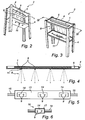
Fig. 2 discloses a perspective bottom view of a module unit, within for example a module system, provided with a first embodiment of the invention. -
Fig. 3 discloses a perspective top view of a module unit, within for example a module system, provided with a second embodiment of the invention. -
Fig. 4 discloses a cross section of IV-IV inFig. 3 of the second embodiment of the invention. -
Fig. 5 discloses a service vehicle illumination system according to a third embodiment of the invention. -
Fig. 6 discloses a service vehicle illumination system according to a fourth embodiment of the invention. - The above, as well as additional objects, features and advantages of the present invention, will be better understood through the following illustrative and non-limiting detailed description of preferred embodiments of the present invention, with reference to the appended drawings, where the same reference to the appended drawings, where the same reference numerals will be used for similar elements, wherein:
-
Fig. 1 shows two servicevehicle illumination systems 1 arranged to twoseparate shelves 4 within amodule system 2 in a cargo or a back space of aservice vehicle 10. However, it should be noticed that theshelf 4 could be any kind of geometric 3D plane. The shelves have two sides, oneupper side 6, onto which articles can be placed, and one opposite underside 5. One servicevehicle illumination system 1 is arranged to the underside 5 of theshelf 4, and the other one is arranged to theupper side 6 of theshelf 4. Theshelf 4, with an arranged servicevehicle illumination system 1 on theupper side 6 will have openings (not shown) along the longitudinal direction, through which the light from the servicevehicle illumination system 1 will light, because in both cases thelight source 9 is placed so that the light 8 from the servicevehicle illumination system 1 illuminates at least a part the opposite underneath lying articles and/orshelf 4. This arrangement will certify that at least one part of themodule system 2 is sufficiently illuminated. The arrangement will also contribute to a better overall cargo or back space illumination of theservice vehicle 10. - The service
vehicle illumination system 1 is connected to a switch 7, which controls the operation manually and/or automatically of the servicevehicle illumination system 1. The switch 7 is arranged externally from the servicevehicle illumination system 1 close to a backdoor of theservice vehicle 10, so that it easily can be controlled manually. The electrical circuitry is not shown in detail in the drawing as it may have to be adapted in accordance with different national standards. -
Fig. 2 shows the servicevehicle illumination system 1 arranged to the underside 5 of theshelf 4 within amodule system 2. Theshelf 4 comprisesopenings 11, which are arranged at a continuous distance in the longitudinal direction of themodule system 2. The form of theopenings 11 may vary. Theseopenings 11 may be used for positioning of the servicevehicle illumination system 1. The servicevehicle illumination system 1 is arranged to the underside 5 of theshelf 4 with fastener means, for example fasteners, screws, double-stick tape etc.(not shown). Thelight source 9 orlight sources 9 of the servicevehicle illumination system 1 are arranged so that the light 8 fromlight sources 9 illuminates at least a part of the opposite underneath lyingshelf 4 and its articles placed thereon. -
Fig. 3 shows the servicevehicle illumination system 1 arranged to theupper side 6 of theshelf 4 within amodule system 2. Theshelves 4 comprisescontinuous openings 11, which are arranged at a continuous distance in the longitudinal direction of themodule system 2. The form of theopenings 11 may vary. Theseopenings 11 are illumination openings, through which the light 8 from thelight source 9 are shining on at least a part the opposite underneath lying, articles and/orshelf 4. -
Fig. 4 shows a cross section the servicevehicle illumination system 1, on theupper side 6 of theshelf 4 with itslight sources 9 passing through theopenings 11 and illuminating the area underneath theshelf 4. However, it is not necessary that thelight sources 9 are passing through theopenings 11 in accordance with this preferred embodiment. It is enough that the light 8 from thelight sources 9 are passing through. -
Fig. 5 shows one embodiment of the servicevehicle illumination system 1. It comprises some sort of armature, for example arail 13, which can be made of rubber, at least one printedcircuit card 14 onto which at least onelight source 9 is arranged and an electric current supplyingmeans 15. The electric current supply mean/means 15 and the printed circuit card/cards 14 may be embedded by therail 13. The servicevehicle illumination system 1 can then be separated through, for example cutting it into smaller or larger pieces so that it can fit into/onto any kind of area. Thelight sources 9 is preferably of LED-type or any other lamp or illuminating device could possibly provide for an illumination system. They are positioned at a distance to each other so that they correspond to theopenings 11 of theshelf 4, especially when the servicevehicle illumination system 1 is arranged to theupper side 6 of ashelf 4 and have to shine through theopenings 11. -
Fig 6 shows another embodiment of the servicevehicle illumination system 1. It is alight module unit 16 which can be connected to otherlight module units 16. A servicevehicle illumination system 1 with different length can on this way be organised. Thelight module unit 16 comprises one printedcircuit card 14, onto which at least onelight source 9 is arranged, and at least one electric current supplying mean 15 adopted for connection. The printedcircuit card 14 can be arranged in some sort of isolatingarrangement 17. The electric current supplyingmeans 15 will then protrude out of the isolatingarrangement 17. At the end parts of the electric current supplying means 15 connection devices can be arranged, which can connect severallight module units 16 to each other. Thelight source 9 is a LED-lamp. However it can be any other lamp or illuminating device. The distance of the connectedlight sources 9 should be arranged at a distance to each other so that they correspond with theopenings 11 of theshelf 4, especially when the servicevehicle illumination system 1 is arranged to theupper side 6 of ashelf 4 and have to light through theopenings 11. - The invention has mainly been described above with reference to some embodiments. However, as is readily appreciated by a person skilled in the art, other embodiments than the ones disclosed above are equally possible within the scope of the invention, as defined by the appended patent claims. Furthermore, the features described in association with different embodiments and aspects of the invention may be combined with the claimed scope in order to enable further embodiments.
Claims (2)
- Shelf system for a back space in a service vehicle (10), comprising at least two levels, one above the other, at least one storage space beneath the lower of said levels, c h a r a c t e r i s e d in that said shelf system further comprises at least two interconnected light sources (9) connectable to an electrical system of said service vehicle (10), wherein said light sources (9) are arranged at the upper of said levels, wherein said lower level comprises an essentially horizontal shelf having the same number of through openings (11) as the number of light sources (9), wherein each one of said through openings is located in register with a respective one of said light sources (9) so that light (8) from said light sources (9) illuminates said storage space through said through openings (11).
- Shelf system according to claim 1, further comprising at least one rail (13), made of for example rubber and at least one printed circuit card (14) which is connected to an electric current supply means (15), said printed circuit card (14) and said electrical current supply means (15) being at least partly embedded in said rail (13).
Applications Claiming Priority (2)
| Application Number | Priority Date | Filing Date | Title |
|---|---|---|---|
| SE0602782A SE530771C2 (en) | 2006-12-22 | 2006-12-22 | Lighting system for service vehicles, use of such a system and a modular system |
| PCT/EP2007/064091 WO2008077843A1 (en) | 2006-12-22 | 2007-12-17 | A service vehicle illumination system, use of such a system and a module system |
Publications (2)
| Publication Number | Publication Date |
|---|---|
| EP2094530A1 EP2094530A1 (en) | 2009-09-02 |
| EP2094530B1 true EP2094530B1 (en) | 2012-08-01 |
Family
ID=39099906
Family Applications (1)
| Application Number | Title | Priority Date | Filing Date |
|---|---|---|---|
| EP07857721A Active EP2094530B1 (en) | 2006-12-22 | 2007-12-17 | A service vehicle illumination system, use of such a system and a module system |
Country Status (3)
| Country | Link |
|---|---|
| EP (1) | EP2094530B1 (en) |
| SE (1) | SE530771C2 (en) |
| WO (1) | WO2008077843A1 (en) |
Cited By (1)
| Publication number | Priority date | Publication date | Assignee | Title |
|---|---|---|---|---|
| DE102021112001A1 (en) | 2021-05-07 | 2022-11-10 | Ford Global Technologies Llc | Lighting system of a permanently enclosed cargo area of a transport vehicle |
Families Citing this family (3)
| Publication number | Priority date | Publication date | Assignee | Title |
|---|---|---|---|---|
| AR078947A1 (en) | 2009-11-11 | 2011-12-14 | Bayer Cropscience Ag | DIAZINIL-PIRAZOLILO COMPOUNDS AND SAME PREPARATION PROCESSES |
| CN102114798B (en) * | 2009-12-31 | 2013-03-13 | 上海市电力公司 | Vehicular intelligent safety instrument cabinet |
| EP3670265B1 (en) * | 2018-12-20 | 2021-07-21 | Schmitz Cargobull AG | Commercial vehicle compartment with lighting device for illuminating the loading space |
Citations (4)
| Publication number | Priority date | Publication date | Assignee | Title |
|---|---|---|---|---|
| US2843729A (en) * | 1955-03-30 | 1958-07-15 | Mink Dayton Inc | Illuminating baggage rack |
| JPH0545048A (en) * | 1991-08-20 | 1993-02-23 | Matsushita Electric Ind Co Ltd | refrigerator |
| JPH05307910A (en) * | 1992-04-30 | 1993-11-19 | Hitachi Chem Co Ltd | Device for fitting luminaire and shelf with luminaire |
| WO2006020945A1 (en) * | 2004-08-13 | 2006-02-23 | Jdm Ventures, Llc | A frame for building an enclosed structure with a load bearing support system |
Family Cites Families (7)
| Publication number | Priority date | Publication date | Assignee | Title |
|---|---|---|---|---|
| US5483427A (en) * | 1994-10-21 | 1996-01-09 | Dealey, Jr.; O. K. | Cargo area lighting system for trucks |
| DE19843330C2 (en) * | 1998-09-22 | 2003-10-16 | Diehl Stiftung & Co | Cabin lighting |
| US6220463B1 (en) * | 1999-12-13 | 2001-04-24 | Jerome A. Pullen | Shelving system |
| US6283612B1 (en) * | 2000-03-13 | 2001-09-04 | Mark A. Hunter | Light emitting diode light strip |
| ES2208040B1 (en) * | 2001-12-26 | 2005-12-16 | Iturri,. S.A | MODULAR SYSTEM OF INTERIOR BODY OF SPECIAL VEHICLES. |
| US6641294B2 (en) * | 2002-03-22 | 2003-11-04 | Emteq, Inc. | Vehicle lighting assembly with stepped dimming |
| US20060181885A1 (en) * | 2005-02-14 | 2006-08-17 | Joel Djong Seng Tong | Light sources embedded in panels |
-
2006
- 2006-12-22 SE SE0602782A patent/SE530771C2/en not_active IP Right Cessation
-
2007
- 2007-12-17 EP EP07857721A patent/EP2094530B1/en active Active
- 2007-12-17 WO PCT/EP2007/064091 patent/WO2008077843A1/en not_active Ceased
Patent Citations (4)
| Publication number | Priority date | Publication date | Assignee | Title |
|---|---|---|---|---|
| US2843729A (en) * | 1955-03-30 | 1958-07-15 | Mink Dayton Inc | Illuminating baggage rack |
| JPH0545048A (en) * | 1991-08-20 | 1993-02-23 | Matsushita Electric Ind Co Ltd | refrigerator |
| JPH05307910A (en) * | 1992-04-30 | 1993-11-19 | Hitachi Chem Co Ltd | Device for fitting luminaire and shelf with luminaire |
| WO2006020945A1 (en) * | 2004-08-13 | 2006-02-23 | Jdm Ventures, Llc | A frame for building an enclosed structure with a load bearing support system |
Cited By (1)
| Publication number | Priority date | Publication date | Assignee | Title |
|---|---|---|---|---|
| DE102021112001A1 (en) | 2021-05-07 | 2022-11-10 | Ford Global Technologies Llc | Lighting system of a permanently enclosed cargo area of a transport vehicle |
Also Published As
| Publication number | Publication date |
|---|---|
| WO2008077843A1 (en) | 2008-07-03 |
| SE0602782L (en) | 2008-06-23 |
| EP2094530A1 (en) | 2009-09-02 |
| SE530771C2 (en) | 2008-09-09 |
Similar Documents
| Publication | Publication Date | Title |
|---|---|---|
| US7682043B2 (en) | Wirelessly controlled light emitting display system | |
| CN101437424B (en) | Piece of furniture | |
| EP2094530B1 (en) | A service vehicle illumination system, use of such a system and a module system | |
| US6824185B2 (en) | Modular overhead console assembly | |
| WO2005119124A3 (en) | Led lighting systems for product display cases | |
| EP1917191B1 (en) | Illumination in the area of aircraft cabins | |
| US10442347B2 (en) | In-vehicle illumination system | |
| US20110041371A1 (en) | Frame having integrated lighting and power supply | |
| CN111463843B (en) | Wireless charging device with optical fiber illuminated visual indicator | |
| DE602007011012D1 (en) | Loading bed system for freight fastening | |
| US6926333B2 (en) | Modular overhead console assembly | |
| US9561749B2 (en) | Pickup truck bed lighting system | |
| US20180037161A1 (en) | Truck bed rail light assembly | |
| US11536429B1 (en) | Wireless lighting device with encapsulated light board | |
| WO2008077842A1 (en) | A module system and use of such a system | |
| EP1526039A3 (en) | Load compartment cover with tying means | |
| US20090279299A1 (en) | Illuminative light device for vehicle | |
| JP6735410B2 (en) | Vehicle luggage compartment structure | |
| US8317378B2 (en) | Bimodal illumination for vehicular storage compartment | |
| EP3764744B1 (en) | Illumination device | |
| JP2023034192A (en) | Vehicular lighting device | |
| WO2006062514A3 (en) | Multi-function lamp for a motor vehicle | |
| JP2015113096A (en) | Indoor lighting device of bus | |
| CN214607493U (en) | Protection mechanism for control console of motor train unit cab | |
| US11618375B2 (en) | Area light integrated in a cabin furnishing element |
Legal Events
| Date | Code | Title | Description |
|---|---|---|---|
| PUAI | Public reference made under article 153(3) epc to a published international application that has entered the european phase |
Free format text: ORIGINAL CODE: 0009012 |
|
| 17P | Request for examination filed |
Effective date: 20090617 |
|
| AK | Designated contracting states |
Kind code of ref document: A1 Designated state(s): AT BE BG CH CY CZ DE DK EE ES FI FR GB GR HU IE IS IT LI LT LU LV MC MT NL PL PT RO SE SI SK TR |
|
| DAX | Request for extension of the european patent (deleted) | ||
| 17Q | First examination report despatched |
Effective date: 20100510 |
|
| GRAP | Despatch of communication of intention to grant a patent |
Free format text: ORIGINAL CODE: EPIDOSNIGR1 |
|
| RIC1 | Information provided on ipc code assigned before grant |
Ipc: B60P 3/14 20060101ALI20120131BHEP Ipc: B60Q 3/06 20060101AFI20120131BHEP Ipc: A47B 97/00 20060101ALI20120131BHEP |
|
| GRAS | Grant fee paid |
Free format text: ORIGINAL CODE: EPIDOSNIGR3 |
|
| GRAA | (expected) grant |
Free format text: ORIGINAL CODE: 0009210 |
|
| AK | Designated contracting states |
Kind code of ref document: B1 Designated state(s): AT BE BG CH CY CZ DE DK EE ES FI FR GB GR HU IE IS IT LI LT LU LV MC MT NL PL PT RO SE SI SK TR |
|
| REG | Reference to a national code |
Ref country code: GB Ref legal event code: FG4D |
|
| REG | Reference to a national code |
Ref country code: AT Ref legal event code: REF Ref document number: 568482 Country of ref document: AT Kind code of ref document: T Effective date: 20120815 Ref country code: CH Ref legal event code: EP |
|
| RIN1 | Information on inventor provided before grant (corrected) |
Inventor name: CARLSSON, HELENE Inventor name: CARLSSON, ANDERS Inventor name: ANDERSSON, KATARINA |
|
| REG | Reference to a national code |
Ref country code: IE Ref legal event code: FG4D |
|
| REG | Reference to a national code |
Ref country code: DE Ref legal event code: R096 Ref document number: 602007024443 Country of ref document: DE Effective date: 20120927 |
|
| REG | Reference to a national code |
Ref country code: SE Ref legal event code: TRGR |
|
| REG | Reference to a national code |
Ref country code: NL Ref legal event code: VDEP Effective date: 20120801 |
|
| REG | Reference to a national code |
Ref country code: AT Ref legal event code: MK05 Ref document number: 568482 Country of ref document: AT Kind code of ref document: T Effective date: 20120801 |
|
| REG | Reference to a national code |
Ref country code: LT Ref legal event code: MG4D Effective date: 20120801 |
|
| PG25 | Lapsed in a contracting state [announced via postgrant information from national office to epo] |
Ref country code: LT Free format text: LAPSE BECAUSE OF FAILURE TO SUBMIT A TRANSLATION OF THE DESCRIPTION OR TO PAY THE FEE WITHIN THE PRESCRIBED TIME-LIMIT Effective date: 20120801 Ref country code: IS Free format text: LAPSE BECAUSE OF FAILURE TO SUBMIT A TRANSLATION OF THE DESCRIPTION OR TO PAY THE FEE WITHIN THE PRESCRIBED TIME-LIMIT Effective date: 20121201 Ref country code: FI Free format text: LAPSE BECAUSE OF FAILURE TO SUBMIT A TRANSLATION OF THE DESCRIPTION OR TO PAY THE FEE WITHIN THE PRESCRIBED TIME-LIMIT Effective date: 20120801 Ref country code: CY Free format text: LAPSE BECAUSE OF FAILURE TO SUBMIT A TRANSLATION OF THE DESCRIPTION OR TO PAY THE FEE WITHIN THE PRESCRIBED TIME-LIMIT Effective date: 20120801 Ref country code: AT Free format text: LAPSE BECAUSE OF FAILURE TO SUBMIT A TRANSLATION OF THE DESCRIPTION OR TO PAY THE FEE WITHIN THE PRESCRIBED TIME-LIMIT Effective date: 20120801 |
|
| PG25 | Lapsed in a contracting state [announced via postgrant information from national office to epo] |
Ref country code: PT Free format text: LAPSE BECAUSE OF FAILURE TO SUBMIT A TRANSLATION OF THE DESCRIPTION OR TO PAY THE FEE WITHIN THE PRESCRIBED TIME-LIMIT Effective date: 20121203 Ref country code: BE Free format text: LAPSE BECAUSE OF FAILURE TO SUBMIT A TRANSLATION OF THE DESCRIPTION OR TO PAY THE FEE WITHIN THE PRESCRIBED TIME-LIMIT Effective date: 20120801 Ref country code: LV Free format text: LAPSE BECAUSE OF FAILURE TO SUBMIT A TRANSLATION OF THE DESCRIPTION OR TO PAY THE FEE WITHIN THE PRESCRIBED TIME-LIMIT Effective date: 20120801 Ref country code: SI Free format text: LAPSE BECAUSE OF FAILURE TO SUBMIT A TRANSLATION OF THE DESCRIPTION OR TO PAY THE FEE WITHIN THE PRESCRIBED TIME-LIMIT Effective date: 20120801 Ref country code: PL Free format text: LAPSE BECAUSE OF FAILURE TO SUBMIT A TRANSLATION OF THE DESCRIPTION OR TO PAY THE FEE WITHIN THE PRESCRIBED TIME-LIMIT Effective date: 20120801 Ref country code: GR Free format text: LAPSE BECAUSE OF FAILURE TO SUBMIT A TRANSLATION OF THE DESCRIPTION OR TO PAY THE FEE WITHIN THE PRESCRIBED TIME-LIMIT Effective date: 20121102 |
|
| PG25 | Lapsed in a contracting state [announced via postgrant information from national office to epo] |
Ref country code: NL Free format text: LAPSE BECAUSE OF FAILURE TO SUBMIT A TRANSLATION OF THE DESCRIPTION OR TO PAY THE FEE WITHIN THE PRESCRIBED TIME-LIMIT Effective date: 20120801 |
|
| PG25 | Lapsed in a contracting state [announced via postgrant information from national office to epo] |
Ref country code: EE Free format text: LAPSE BECAUSE OF FAILURE TO SUBMIT A TRANSLATION OF THE DESCRIPTION OR TO PAY THE FEE WITHIN THE PRESCRIBED TIME-LIMIT Effective date: 20120801 Ref country code: CZ Free format text: LAPSE BECAUSE OF FAILURE TO SUBMIT A TRANSLATION OF THE DESCRIPTION OR TO PAY THE FEE WITHIN THE PRESCRIBED TIME-LIMIT Effective date: 20120801 Ref country code: ES Free format text: LAPSE BECAUSE OF FAILURE TO SUBMIT A TRANSLATION OF THE DESCRIPTION OR TO PAY THE FEE WITHIN THE PRESCRIBED TIME-LIMIT Effective date: 20121112 Ref country code: RO Free format text: LAPSE BECAUSE OF FAILURE TO SUBMIT A TRANSLATION OF THE DESCRIPTION OR TO PAY THE FEE WITHIN THE PRESCRIBED TIME-LIMIT Effective date: 20120801 Ref country code: DK Free format text: LAPSE BECAUSE OF FAILURE TO SUBMIT A TRANSLATION OF THE DESCRIPTION OR TO PAY THE FEE WITHIN THE PRESCRIBED TIME-LIMIT Effective date: 20120801 |
|
| PG25 | Lapsed in a contracting state [announced via postgrant information from national office to epo] |
Ref country code: IT Free format text: LAPSE BECAUSE OF FAILURE TO SUBMIT A TRANSLATION OF THE DESCRIPTION OR TO PAY THE FEE WITHIN THE PRESCRIBED TIME-LIMIT Effective date: 20120801 Ref country code: SK Free format text: LAPSE BECAUSE OF FAILURE TO SUBMIT A TRANSLATION OF THE DESCRIPTION OR TO PAY THE FEE WITHIN THE PRESCRIBED TIME-LIMIT Effective date: 20120801 |
|
| PLBE | No opposition filed within time limit |
Free format text: ORIGINAL CODE: 0009261 |
|
| STAA | Information on the status of an ep patent application or granted ep patent |
Free format text: STATUS: NO OPPOSITION FILED WITHIN TIME LIMIT |
|
| 26N | No opposition filed |
Effective date: 20130503 |
|
| PG25 | Lapsed in a contracting state [announced via postgrant information from national office to epo] |
Ref country code: BG Free format text: LAPSE BECAUSE OF FAILURE TO SUBMIT A TRANSLATION OF THE DESCRIPTION OR TO PAY THE FEE WITHIN THE PRESCRIBED TIME-LIMIT Effective date: 20121101 Ref country code: MC Free format text: LAPSE BECAUSE OF NON-PAYMENT OF DUE FEES Effective date: 20121231 |
|
| REG | Reference to a national code |
Ref country code: CH Ref legal event code: PL |
|
| REG | Reference to a national code |
Ref country code: DE Ref legal event code: R097 Ref document number: 602007024443 Country of ref document: DE Effective date: 20130503 |
|
| REG | Reference to a national code |
Ref country code: IE Ref legal event code: MM4A |
|
| PG25 | Lapsed in a contracting state [announced via postgrant information from national office to epo] |
Ref country code: CH Free format text: LAPSE BECAUSE OF NON-PAYMENT OF DUE FEES Effective date: 20121231 Ref country code: LI Free format text: LAPSE BECAUSE OF NON-PAYMENT OF DUE FEES Effective date: 20121231 Ref country code: IE Free format text: LAPSE BECAUSE OF NON-PAYMENT OF DUE FEES Effective date: 20121217 |
|
| PG25 | Lapsed in a contracting state [announced via postgrant information from national office to epo] |
Ref country code: MT Free format text: LAPSE BECAUSE OF FAILURE TO SUBMIT A TRANSLATION OF THE DESCRIPTION OR TO PAY THE FEE WITHIN THE PRESCRIBED TIME-LIMIT Effective date: 20120801 |
|
| PG25 | Lapsed in a contracting state [announced via postgrant information from national office to epo] |
Ref country code: TR Free format text: LAPSE BECAUSE OF FAILURE TO SUBMIT A TRANSLATION OF THE DESCRIPTION OR TO PAY THE FEE WITHIN THE PRESCRIBED TIME-LIMIT Effective date: 20120801 |
|
| PG25 | Lapsed in a contracting state [announced via postgrant information from national office to epo] |
Ref country code: LU Free format text: LAPSE BECAUSE OF NON-PAYMENT OF DUE FEES Effective date: 20121217 |
|
| PG25 | Lapsed in a contracting state [announced via postgrant information from national office to epo] |
Ref country code: HU Free format text: LAPSE BECAUSE OF FAILURE TO SUBMIT A TRANSLATION OF THE DESCRIPTION OR TO PAY THE FEE WITHIN THE PRESCRIBED TIME-LIMIT Effective date: 20071217 |
|
| REG | Reference to a national code |
Ref country code: FR Ref legal event code: PLFP Year of fee payment: 9 |
|
| REG | Reference to a national code |
Ref country code: DE Ref legal event code: R079 Ref document number: 602007024443 Country of ref document: DE Free format text: PREVIOUS MAIN CLASS: B60Q0003060000 Ipc: B60Q0003300000 |
|
| REG | Reference to a national code |
Ref country code: FR Ref legal event code: PLFP Year of fee payment: 10 |
|
| REG | Reference to a national code |
Ref country code: FR Ref legal event code: PLFP Year of fee payment: 11 |
|
| PGFP | Annual fee paid to national office [announced via postgrant information from national office to epo] |
Ref country code: FR Payment date: 20201117 Year of fee payment: 14 Ref country code: GB Payment date: 20201117 Year of fee payment: 14 |
|
| GBPC | Gb: european patent ceased through non-payment of renewal fee |
Effective date: 20211217 |
|
| PG25 | Lapsed in a contracting state [announced via postgrant information from national office to epo] |
Ref country code: GB Free format text: LAPSE BECAUSE OF NON-PAYMENT OF DUE FEES Effective date: 20211217 |
|
| PG25 | Lapsed in a contracting state [announced via postgrant information from national office to epo] |
Ref country code: FR Free format text: LAPSE BECAUSE OF NON-PAYMENT OF DUE FEES Effective date: 20211231 |
|
| PGFP | Annual fee paid to national office [announced via postgrant information from national office to epo] |
Ref country code: DE Payment date: 20251121 Year of fee payment: 19 |
|
| PGFP | Annual fee paid to national office [announced via postgrant information from national office to epo] |
Ref country code: SE Payment date: 20251114 Year of fee payment: 19 |