EP2094494B1 - Tintendruckregler - Google Patents
Tintendruckregler Download PDFInfo
- Publication number
- EP2094494B1 EP2094494B1 EP06828019A EP06828019A EP2094494B1 EP 2094494 B1 EP2094494 B1 EP 2094494B1 EP 06828019 A EP06828019 A EP 06828019A EP 06828019 A EP06828019 A EP 06828019A EP 2094494 B1 EP2094494 B1 EP 2094494B1
- Authority
- EP
- European Patent Office
- Prior art keywords
- ink
- pressure
- air
- bubble
- chamber
- Prior art date
- Legal status (The legal status is an assumption and is not a legal conclusion. Google has not performed a legal analysis and makes no representation as to the accuracy of the status listed.)
- Not-in-force
Links
Images


Classifications
-
- B—PERFORMING OPERATIONS; TRANSPORTING
- B41—PRINTING; LINING MACHINES; TYPEWRITERS; STAMPS
- B41J—TYPEWRITERS; SELECTIVE PRINTING MECHANISMS, i.e. MECHANISMS PRINTING OTHERWISE THAN FROM A FORME; CORRECTION OF TYPOGRAPHICAL ERRORS
- B41J2/00—Typewriters or selective printing mechanisms characterised by the printing or marking process for which they are designed
- B41J2/005—Typewriters or selective printing mechanisms characterised by the printing or marking process for which they are designed characterised by bringing liquid or particles selectively into contact with a printing material
- B41J2/01—Ink jet
- B41J2/17—Ink jet characterised by ink handling
- B41J2/19—Ink jet characterised by ink handling for removing air bubbles
-
- B—PERFORMING OPERATIONS; TRANSPORTING
- B41—PRINTING; LINING MACHINES; TYPEWRITERS; STAMPS
- B41J—TYPEWRITERS; SELECTIVE PRINTING MECHANISMS, i.e. MECHANISMS PRINTING OTHERWISE THAN FROM A FORME; CORRECTION OF TYPOGRAPHICAL ERRORS
- B41J2/00—Typewriters or selective printing mechanisms characterised by the printing or marking process for which they are designed
- B41J2/005—Typewriters or selective printing mechanisms characterised by the printing or marking process for which they are designed characterised by bringing liquid or particles selectively into contact with a printing material
- B41J2/01—Ink jet
- B41J2/17—Ink jet characterised by ink handling
- B41J2/175—Ink supply systems ; Circuit parts therefor
- B41J2/17503—Ink cartridges
- B41J2/17513—Inner structure
-
- B—PERFORMING OPERATIONS; TRANSPORTING
- B41—PRINTING; LINING MACHINES; TYPEWRITERS; STAMPS
- B41J—TYPEWRITERS; SELECTIVE PRINTING MECHANISMS, i.e. MECHANISMS PRINTING OTHERWISE THAN FROM A FORME; CORRECTION OF TYPOGRAPHICAL ERRORS
- B41J2/00—Typewriters or selective printing mechanisms characterised by the printing or marking process for which they are designed
- B41J2/005—Typewriters or selective printing mechanisms characterised by the printing or marking process for which they are designed characterised by bringing liquid or particles selectively into contact with a printing material
- B41J2/01—Ink jet
- B41J2/17—Ink jet characterised by ink handling
- B41J2/175—Ink supply systems ; Circuit parts therefor
- B41J2/17503—Ink cartridges
- B41J2/17556—Means for regulating the pressure in the cartridge
Definitions
- the present invention relates to a pressure regulator for an inkjet printer. It has been developed primarily for generating a negative hydrostatic pressure in an ink supply system supplying ink to printhead nozzles.
- the inkjet printheads described in the above cross referenced documents typically comprise an array of nozzles, each nozzle having an associated ink ejection actuator for ejecting ink from a nozzle opening defined in a roof of a nozzle chamber. Ink from an ink cartridge or other reservoir is fed to the chambers where the ejection actuators force droplets of ink through the nozzle opening for printing.
- an ink cartridge is a replaceable consumable in an inkjet printer.
- Ink may be drawn into each nozzle chamber by suction generated after each drop ejection and by the capillary action of ink supply channels having hydrophilic surfaces (e.g. silicon dioxide surface).
- ink is retained in the nozzle chambers by the surface tension of an ink meniscus pinned across a rim of each nozzle opening.
- the ink pressure is not controlled, it may become positive with respect to external atmospheric pressure, possibly by thermal expansion of the ink, or a tipping of the printer that elevates the ink above the level of the nozzles. In this case the ink will flood onto the printhead surface.
- ink supplied through the ink supply channels has a momentum, which is sufficient to surge out of the nozzles and flood the printhead face once printing stops. Printhead face flooding is clearly undesirable in either of these scenarios.
- printhead ink supply systems are designed so that a hydrostatic pressure of ink at the nozzles is less than atmospheric pressure. This causes the meniscus across the nozzle openings to be concave or drawn inwards. The meniscus is pinned at nozzle openings, and the ink cannot freely flow out of the nozzles, both during inactive periods. Furthermore, face flooding as a result of ink surges are minimized.
- inkjet printers may have a relatively narrow window of hydrostatic ink pressures, which must be achieved by a pressure regulator in the ink supply system.
- ink cartridges are designed to incorporate some means for regulating hydrostatic pressure of ink supplied therefrom.
- some cartridges use a flexible bag design. Part of the cartridge has a flexible bag or wall section that is biased towards increasing the ink storage volume.
- USSN 11/014764 (Our Docket: RRB001US) and USSN 11/014769 (Our Docket: RRC001US) (listed above in the cross referenced documents) are examples of this type of cartridge.
- These cartridges can provide a negative pressure, but tend to rely on excellent manufacturing tolerances of an internal leaf spring in the flexible bag. Further, the requirement of an internal biasing means in a flexible bag presents significant manufacturing difficulties.
- FIG 17 Another means of generating a negative ink pressure via the ink cartridge is shown in Figure 17 .
- a piece of foam or porous material 2 is placed in the cartridge 1 over the outlet 3.
- the foam 2 has a section that is saturated with ink 4, and a section 5 that may be wet with ink, but not saturated.
- the top of the cartridge 1 is vented to atmosphere through the air maze 7.
- Capillary action (represented by arrow 6) draws the ink from the saturated section 4 into the unsaturated section 5. This continues until it is balanced by the weight of the increased hydrostatic pressure, or 'head' of ink drawn upwards by the capillary action 6.
- the hydrostatic pressure at the top of the saturated section 4 is less than atmospheric because of capillary action into the unsaturated section 5.
- the hydrostatic pressure increases towards the outlet 3, and if connected to the printhead (not shown), it continues to increase down to the nozzle openings (assuming they are the lowest points in the printhead).
- the proportion of saturated foam to unsaturated foam such that the hydrostatic pressure of the ink at the nozzle is less than atmospheric, the ink meniscus will form inwardly.
- ink cartridges comprising foam inserts are generally unsuitable for high speed printing (e.g . print speeds of one page every 1-2 seconds) using the Applicant's pagewidth printheads, which print at up to 1600 dpi.
- high speed printers there are a large number of nozzles having a higher firing rate than traditional scanning printers. Therefore the ink flow rate out of the cartridge is much greater than that of a scanning printhead.
- the hydraulic drag caused by the foam insert can starve the nozzles and retard the chamber refill rate. More porous foam would have less hydraulic drag but also much less capillary force.
- accurate pressure control requires equally accurate control over the internal void dimensions, which is difficult to achieved by the stochastically formed void structures of most foam materials. Accordingly, porous foam inserts are not considered to be a viable means for controlling ink pressure at high ink flow rates.
- the ink supply system may comprise a pressure regulator in the ink line between the printhead and an ink reservoir.
- the present Applicant's previously filed US Application Nos. 11/293,806 (Attorney Docket No. RRD011US, filed on December 5, 2005) and 11/293,842 (Attorney Docket No. RRD008US, filed on December 5, 20055) describe an in-line pressure regulator comprising a diaphragm and biasing mechanism. This mechanical arrangement is used to generate a negative hydrostatic ink pressure at the printhead.
- this type of mechanical pressure regulator has the drawback of requiring extremely fine manufacturing tolerances for a spring, which opens and closes the diaphragm in response to fluctuations in ink pressure upstream and downstream of the diaphragm.
- this mechanical system of pressure control makes it difficult to implement in an ink supply system required to maintain a constant negative hydrostatic ink pressure within a relatively narrow pressure range.
- a pressure regulator which is suitable for maintaining a hydrostatic ink pressure within a relatively narrow pressure range. It would further be desirable to provide a pressure regulator, which is suitable for use at relatively high ink flow rates. It would further be desirable to provide a pressure regulator, which is simple in construction and which does not require a plethora of moving parts manufactured with high tolerances.
- a first embodiment of the invention provides an ink pressure regulator as detailed in claim 1.
- Advantageous embodiments are provided in the dependent claims.
- Figs. 10-14 The present invention is disclosed with reference to Figs. 10-14 .
- the other embodiments disclosed in Figs. 1-9 are examples which are useful for understanding the invention.
- FIG. 1 shows the simplest form of a pressure regulator, for the purposes of explaining the basic operating principle of the pressure regulator.
- a pressure regulator 100 comprising an ink chamber 101 having an ink outlet 102 and air inlet 103.
- the ink chamber 101 is otherwise sealed.
- the ink outlet 102 is for supplying ink 104 to a printhead 105 via an ink line 106.
- a bubble outlet 107 is connected to the air inlet 103 via an air channel 108.
- the displaced volume of ink must be balanced with an equivalent volume of air, which is drawn into the chamber via the air inlet 103.
- the bubble outlet 107 which is positioned below the level of ink, ensures that the air enters the chamber 101 in the form of air bubbles 109.
- the dimensions of the bubble outlet 107 determine the size of the air bubbles 109 entering the chamber 101.
- the air channel 108 takes the form of a simple cylindrical channel, so that the bubble outlet 107 is defined by a circular opening at one end of the cylindrical channel. Accordingly, any air passing through the channel must at some point be bounded by a liquid surface with radius of curvature not greater than the internal radius of the channel.
- the nozzles on the printhead 105 effectively act as a pump, drawing ink from the ink chamber 101 with each drop ejection. If the ink chamber were left freely open to atmosphere with an air vent (as in some prior art ink cartridges), the hydrostatic ink pressure of the ink supplied to the printhead would be simply be the determined by the elevation of the ink reservoir above or below the printhead. However, in the ink chamber 101, each time a microscopic volume of ink is drawn from the chamber 101, it must overcome the pressure inside an air bubble 109 forming at the bubble outlet 107.
- the air bubbles 109 forming at the bubble outlet 107 provide a back pressure against the pumping effect of the printhead nozzles.
- the effect of the bubble outlet 107 is to generate a negative hydrostatic ink pressure in the ink supply system.
- the size of the air bubbles 109 can be varied by varying the dimensions of the bubble outlet 107. Therefore, the dimensions of the bubble outlet 107 provides a means of establishing a predetermined negative hydrostatic pressure of ink supplied to the printhead 105. Smaller bubble outlet dimensions provide a larger negative hydrostatic ink pressure by virtue of generating smaller air bubbles having a higher Laplace pressure.
- the air channel 108 is a small-bored cylinder (e.g. hypodermic needle) having a circular opening defining the bubble outlet 107.
- the circular bubble outlet 107 has a very small area (of the order of about 0.01 mm 2 ) and is susceptible to blockages by contaminants in the ink. It would be desirable to increase the area of the bubble outlet 107 so that it is more robust, even if there are contaminants in the ink.
- an improved design of bubble outlet 107 uses a slot 110, as opposed to a circular opening.
- the slot has a length dimension L and a width dimension W.
- the air bubbles 109 exiting the slot typically have a cylindrical front extending across the length of the slot.
- the curvature of the air bubbles 109 exiting the slot and, hence, the Laplace pressure of the air bubbles is determined primarily by the width dimension.
- the width of the slot 110 is the only critical dimension controlling the Laplace pressure of the air bubbles 109 exiting the slot.
- Figure 3B shows a hypothetical scenario where a piece of debris 111 has become stuck to the slot 110.
- the slot 110 is still able to control the critical curvature of bubbles exiting the slot.
- An air bubble 109 having a cylindrical front can still exit the slot 110 as shown in Figure 3B .
- the slot 110 provides a more robust design for the bubble outlet 107, whilst still maintaining excellent control of the hydrostatic ink pressure.
- the dimensions of the air channel 108 mirror the dimensions of the bubble outlet 107. This is not an essential feature of the regulator and, in fact, may adversely affect the efficacy of the regulator, particularly at high flow rates.
- the inherent viscosity of air can cause a significant flow resistance or hydraulic drag in the air channel 108.
- flow rate has an r 4 relationship with pipe radius r. Hence, the problem of flow resistance is exacerbated in channels having very small radii.
- a critical dimension of the bubble outlet 107 is optionally less than about 200 microns, or optionally less than about 150 microns, or optionally less than about 100 microns, or optionally less than about 75 microns or optionally less than about 50 microns.
- the critical dimension of the bubble outlet may be in the range of 10 to 50 microns or 15 to 40 microns.
- critical dimension it is meant the dimension of the bubble outlet determining the curvature and, hence, the Laplace pressure of the air bubbles.
- the desired negative hydrostatic ink pressure which is optionally at least 10 mmH 2 O, or optionally at least 30 mmH 2 O, or optionally at least 50 mmH 2 O for a photo-sized printhead.
- the desired negative hydrostatic ink pressure is optionally at least 100 mmH 2 O, or optionally at least 200 mmH 2 O, or optionally at least 300 mmH 2 O.
- the negative hydrostatic pressure may be in the range of 100 to 500 mmH 2 O or 150 to 450 mmH 2 O
- the air channel 108 having a width of, say, less than 200 microns, generates significant flow resistance for air entering the channel. If air is unable to pass through the channel 108 at the same flow rate as ink is supplied to the printhead 105, then a catastrophic deprime of the printhead would result at high print-speeds.
- each cross-sectional dimension of the air channel is larger than the critical dimension of the bubble outlet 107.
- the air channel 108 should optionally have each cross-sectional dimension greater than the width W of the slot 110.
- the volume of the air channel 108 is not too large.
- ink may rise up the air channel 108 by capillary action. This volume of ink must be pulled through the air channel 108 by the printhead 105 before air bubbles 109 are drawn into the ink chamber 101 and the optimal hydrostatic ink pressure for printing is reached.
- a volume of ink drawn into the air channel 108 by capillary action during idle periods will be wasted, since it cannot be printed with optimal print quality.
- the capillary volume of ink increases with the radius of the air channel. Accordingly, the cross-sectional dimensions (e.g. radius) of the air channel 108 should optionally not be so large that the maximum capillary volume exceeds about 0.1 mL of ink, which is effectively a dead volume of ink.
- the maximum capillary volume of ink in the air channel is less than about 0.08 mL, or optionally less than about 0.05 mL, or optionally less than about 0.03mL.
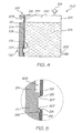
- FIG. 4 shows an alternative ink pressure regulator 200 having a bubble outlet 207 and air channel 208 with the abovementioned design considerations taken into account.
- the pressure regulator 200 comprises an ink chamber 201 having an ink outlet 102.
- One sidewall of the ink chamber 201 is defined by a laminated air intake plate 210 comprising first and second planar layers 211 and 212.
- the first and second layers 211 and 212 have respective first and second faces 221 and 222 which cooperate to define the air inlet 203, the air channel 208 and the bubble outlet 207.
- the air inlet 203 may optionally comprise an air filter (not shown) for filtering particulates from air drawn into the ink chamber 201.
- the ink chamber 201 also comprises a one-way pressure release valve 219, which is normally closed during operation of the pressure regulator 200.
- the valve 219 is configured to release any positive pressure in a headspace 240 above the ink 104, which may, for example, result from thermal expansion of a volume of air trapped in the headspace during typical day/night temperature fluctuations.
- a positive pressure in the headspace 240 is undesirable because it forces ink up the air channel 208 and out of the air inlet 203, leading to appreciable ink losses from the chamber 201.
- the first layer 211 of the air intake plate 210 has an air inlet opening 213 defined therethrough and an elongate recess 214 in the form of a groove defined in the first face 221.
- the elongate recess 214 extends from the air inlet opening 213 to a recessed terminus region.
- the recessed terminus region comprises a circular recess 216 which has a relatively shallow depth compared to the elongate recess 214.
- the second layer 212 has a bubble vent opening 217 defined therethrough.
- the recesses and openings cooperate to define the air inlet 203, the air channel 208 and the bubble outlet 207.
- Figure 5 shows in detail a bubble outlet region 220 of the air intake plate 210.
- the circular recess 216 being shallower than the elongate recess 214, defines a constriction 218 in the air channel 108.
- the bubble outlet 207 therefore takes the form of an annular slot with a length of the slot being defined by a circumference of the bubble vent opening 217 in the second layer 212.
- An advantage of having an annular slot is that it maximizes the length of the slot, thereby improving the robustness of the bubble outlet 207 to particulate contamination.
- An advantage of having a relatively deep elongate recess 214 is that it minimizes flow resistance in the air channel 108 defined by cooperation of the recess 214 and the second face 222.
- the elongate recess 214 has a depth in the range of 0.2 to 1 mm or 0.2 to 0.5 mm, and a width in the range of 0.5 to 2 mm or 0.7 to 1.3 mm.
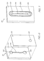
- the first layer 211 of the air intake plate 210 may have a moat 230 defined therein.
- the moat 230 surrounds the features defined in the first layer 211 and, importantly, protects the elongate recess 214 and circular recess 216 from any adhesive during the lamination process.
- the wicking of any excess adhesive between the first and second faces 221 and 222 is arrested by the moat 230 as capillary action can only transport liquids into of structures ever decreasing dimensions, and any path across the moat includes a region of increasing dimension. This prevents blocking of the air inlet channel 208 or the bubble outlet opening 207, which are defined by lamination of the two layers.
- the moat 230 is a feature, which facilitates manufacture of the air intake plate 210.
- the air intake plate may take many different forms and may, for example, be defined by cooperation of more than two laminated layers.
- Figure 8 shows an air intake plate 250 defined by cooperation of three layers.
- a first layer 251 has an air inlet opening 252 defined therethrough;
- a second layer 253 has an bubble vent opening 254 defined therethrough;
- a third film layer 255 is sandwiched between the first and second layers.
- the film layer 255 has an air channel opening 256 defined therethrough, so that when the three layers are laminated together a fluidic path is defined from an air inlet to the bubble vent.
- the thickness of the film layer 255 defines the depth of the air channel and the critical dimension of the bubble outlet at the terminus of the air channel.
- Tables 1 to 4 below show measured hydrostatic ink pressures for the pressure regulator 200 shown in Figures 4 to 6 .
- Four pressure regulators were constructed having different critical dimensions of the bubble outlet 207. Dynamic pressure measurements were made at various flow rates and static pressure measurements were made by stopping the flow of ink. The dynamic pressure loss is the difference between the dynamic regulating pressure and the static regulating pressure.
- the surface tension ⁇ of the ink was calculated as 33.5 mN/m. Independent surface tension measurements of the ink correlated well with this calculated figure.
- the pressure regulator 200 comprises an ink chamber 201, which defines an ink reservoir for the printhead. Due to the simplicity and low-cost manufacture of the pressure regulator 200, it may be constructed as a replaceable ink cartridge for an inkjet printer. Hence, each time the ink cartridge is replaced, the pressure regulator is replaced. An advantage of this design is that long-term fouling of the pressure regulator 200 is avoided, because it is periodically replaced during the lifetime of the printer.
- the pressure regulator may be a permanent component of a printer.
- the pressure regulator is configured for connection to a replaceable ink cartridge.
- the pressure regulator 200 is connected to a replaceable ink cartridge 280 via a pair of connectors.
- An ink connector 281 connects an ink supply port 282 of the ink cartridge 280 with an ink inlet port 283 of the ink chamber 201.
- the ink supply port 282 and corresponding ink inlet port 283 are positioned towards a base of the ink cartridge 280 and ink chamber 201 respectively, to maximize usage of ink 104 stored in the cartridge.
- a pressure-equalizing connector 285 is positioned to equalize pressure in the headspace 240 of the ink chamber 201 and a headspace 241 of the ink cartridge 280.
- Corresponding pressure-equalizing ports 286 and 287 are positioned towards a roof of the ink chamber 201 and ink cartridge 280, respectively.
- the ink cartridge 280 When the ink cartridge 280 is empty, it is disconnected from the ink connector 281 and the pressure-equalizing connector 285, and removed from the printer. A new ink cartridge can then be installed in the printer by the reverse process.
- the ink cartridge 280 may have suitable connection ports 282 and 287, which are configured for sealing engagement with the ink connector 281 and pressure-equalizing connector 285, respectively, when the ink cartridge is installed in the printer. Connection ports suitable for such sealing engagement are well known in the art.
- the ink inlet port 283 and pressure-equalizing port 286 are defined in a sidewall of the ink chamber 201 which is opposite to the air intake plate 210.
- the ports 283 and 286, may of course be defined in the air intake plate 210 so as to simplify construction of the pressure regulator 200.
- the bubble outlet 207 is positioned so as to bubble air bubbles 209 into a body of ink 104 contained in the ink chamber 201.
- the bubble outlet 207 is positioned towards a base of the chamber 201 in order to maximize ink usage at optimal hydrostatic pressure, with the air inlet 203 being positioned towards a roof of the chamber.
- a problem with this arrangement is that ink 104 contained in the chamber 201 can easily escape up the air channel 208 and out of the air inlet 203 during idle periods as a consequence of temperature fluctuations, whereby heating air in the headspace 240 increase the headspace pressure and forces ink up the air channel 208 and out of the air inlet 203. Such temperature fluctuations are unavoidable and can result in significant ink wastage.
- valve 219 is configured to release any positive pressure in the headspace 240.
- valves of this type add significantly to the cost and complexity of the pressure regulator.
- the pressure-release valve 219 makes the pressure regulator 200 less amenable for incorporation into a disposable ink cartridge.
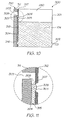
- Figure 10 shows an ink pressure regulator 300 according to the present invention, which meets the above-mentioned criteria.
- the ink pressure regulator is similar in design to that shown in Figure 4 and still relies on controlling the Laplace pressure of air bubbles entering the ink chamber. However, rather than air bubbles bubbling into a body of ink contained in the chamber, the air bubbles enter the chamber via the headspace above the body of the ink. This design enables any excess pressure in the headspace to vent through the air inlet during idle periods, as will be explained in more detail below.
- the ink pressure regulator 300 comprises an ink chamber 301 having an ink outlet 302.
- One sidewall of the ink chamber 301 is defined by a laminated air intake plate 310 comprising first and second planar layers 311 and 312, which cooperate to define an air inlet 303, a bubble outlet 307, a bubble vent 305, an air channel 308, a capillary channel 315 and a capillary inlet 316.
- the bubble outlet 307 and bubble vent 305 are positioned above the level of ink in the chamber 301 so that air bubbles 309 enter the headspace 340 of the chamber via the bubble vent.
- the bubble outlet 307 is connected to the air inlet 303 via the air channel 308.
- the bubble outlet 307 is generally slot-shaped and is critically dimensioned to control the Laplace pressure of air bubbles 309 as ink is drawn from the ink outlet 302.
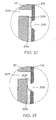
- the air bubbles 309 are formed by air breaking through a meniscus of ink pinned across the bubble outlet 307 and adjacent bubble vent 305, as shown more clearly in Figure 11 .
- the so-formed air bubbles 309 emerging from the bubble outlet 307 escape through the bubble vent 305 and into the headspace 340 of the ink chamber 301. Since the air must break through an ink meniscus, the air bubbles 309 are defined by an air cavity trapped inside a film of ink, rather than a whole body of ink. Regardless, the same Laplacian pressure control is still achievable, as described above.
- the capillary inlet 316 provides fluid communication between the body of ink 104 in the chamber 301 and the capillary channel 315 defined between the two layers 311 and 312.
- the capillary channel 315 is configured to provide sufficient capillary pressure such that a column of ink 304 rises up the channel at least as high as the bubble outlet 307, thereby ensuring formation of air bubbles 309 by air breaking through a meniscus of ink.
- the capillary pressure is sufficiently high to re-form a meniscus across the bubble outlet 307 and bubble vent 305 after each air bubble 309 has vented into the headspace 340.
- the bubble vent 305 is dimensioned such that the column of ink 304 has a meniscus pinned across the vent by surface tension, as shown in Figures 11 and 12 .
- the bubble vent 305 should not be so small that it is susceptible to blockage by particulates.
- a bubble vent 305 having a diameter of the order of about 1 mm has been found to be suitable.
- Figure 13 shows the situation where a positive pressure is built up in the headspace 340 during an idle period.
- the pressurized air forces any ink from the air channel 308 and the air escapes from the chamber 301 via the air inlet 303. Accordingly, only minute quantities of ink escape from the chamber 301 when the headspace 340 becomes pressurized due to temperature rises.
- a further advantage of the present embodiment is that the air channel 308 is relatively short, thereby minimizing any flow resistance in the air channel and allowing high flow rates of ink from the chamber 301 with optimal pressure control. Any flow resistance problems (such as those described above in connection with the embodiment shown in Figure 4 ) are therefore avoided.
- the pressure regulators described herein may be incorporated into an ink supply system for an inkjet printer.
- the Applicant has developed previously a circulatory ink supply system comprising a pair of peristaltic pumps.
- the pumps are configurable for priming, depriming and printhead purging operations.
- This ink supply system is described in US Application No. 11/415,819 , the contents of which is herein incorporated by reference.
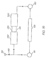
- FIG 15 shows schematically a circulatory ink supply system incorporating an ink pressure regulator according to the present invention.
- the ink pressure regulator 300 is connected to a replaceable ink cartridge 280 via an ink connector 281 and a pressure-equalizing connector 285.
- the ink pressure regulator 300 may be incorporated into a replaceable ink cartridge, as already described above.
- the ink supply system comprises a printhead 105 connected to an upstream pump 150 and a downstream pump 151.
- the ink cartridge 280 and ink pressure regulator 300 complete the circuit.
- the upstream pump 150 is left open and the ink pressure regulator 300 controls the hydrostatic ink pressure in the system.
- both pumps 150 and 151 are shut off to isolate the printhead 105. Priming of the printhead 105 can be achieved by pumping ink to the printhead using the upstream pump 150. Similarly, depriming of the printhead 105 can be achieved by pumping ink from the printhead back to the ink cartridge 280 using downstream pump 151.
- the ink cartridge 280 typically comprises a filter for filtering any ink returned to it by the downstream pump 151.
- the printhead 105 may also be purged with air supplied from air inlet 152 by opening check valve 153 and pumping the downstream pump 151 in a reverse direction.
- the air purge generates a froth or foam of ink at the printhead face, which is used for maintenance operations, as described in our copending US Application Nos. 11/495,815 , 11/495,816 and 11/495,817 , the contents of which are herein incorporated by reference.
- the pressure regulator and/or ink cartridge are required to have a plurality of apertures or ports (e.g . bubble outlet, pressure-release valve, ink return inlet etc .). Each of these represents a potential leakage point for ink, especially if the pressure regulator and/or ink cartridge is tipped. Any leakage of ink, other than in the supply of ink to the printhead, is clearly undesirable.
- the pressure regulator and/or ink cartridge should be designed in such a way as to minimize undesirable leakages via, for example, the bubble outlet.
- Certain design criteria are immutable: if the bubble outlet bubbles air into the ink, then it must be positioned towards the base of the ink chamber; the ink outlet must also be positioned towards the base of the ink chamber; the pressure-release outlet must be positioned towards a roof of the ink chamber.
- Figure 16 shows schematically a combined pressure regulator/ink cartridge system of the type shown in Figure 9 , which is suitable for use in the ink supply system shown in Figure 15 .
- the system comprises an ink chamber 201, an ink cartridge 280 and an air intake plate 210.
- the air intake plate 210 is fixed to the ink chamber 201 and the ink cartridge 280 is removably engaged with the air intake plate.
- Ink is supplied from ink chamber 201 via ink outlet 202 and ink is returned to the ink cartridge 280 via ink return inlet 290, which feeds ink to an ink return opening 291 in the air intake plate 210 and into a return conduit 292 extending longitudinally in the headspace 241 of the ink cartridge 280.
- a pressure-equalizing conduit 293 adjacent the ink return conduit 292 communicates with the headspace 241 in the ink chamber via pressure-equalizing ports 286 and 287.
- Ink is fed from the ink cartridge 280 to the ink chamber 201 via an ink outlet port 282 communicating with a corresponding ink inlet port 283 in the ink chamber.
- An ink supply conduit 294 extends longitudinally along the base of the ink cartridge and supplies ink to the ink outlet port 282. The use of longitudinal conduits 294, 293 and 292 in the ink cartridge minimizes ink leakages when the cartridge is tipped.
- the air intake plate 210 comprises the bubble outlet 207 in a first corner and the pressure-release valve 219 in an opposite second corner.
- the air inlet 203 is positioned at the second corner and the air channel 208 is bent towards the second corner.
- a pressure-release outlet 296 is positioned at the first corner and a pressure-release channel 297 communicating with the pressure-release valve 219 is bent towards the first corner.
Landscapes
- Ink Jet (AREA)
Claims (10)
- Ein Tintendruckregler (300) zum Regeln eines hydrostatischen Drucks von Tinte, die einem Tintenstrahldruckkopf zugeführt wird, wobei der Regler folgendes umfasst:eine Tintenkammer (301) mit einem Tintenauslass (302) für die Fluidverbindung mit dem Druckkopf über eine Tintenleitung;einen gegenüber der Atmosphäre offenen Lufteinlass (303);einen Bläschenauslass (307) zum Einblubbern von Luftbläschen (309) in einen Kopfraum (340) über der Tinte (104), die in der Kammer enthalten ist, wobei jedes Luftbläschen einen Lufthohlraum umfasst, der in einem Tintenfilm gefangen ist; undeinen Luftkanal (308), der den Lufteinlass und den Bläschenauslass verbindet,wobei der Bläschenauslass (307) bemessen ist, um einen Laplace-Druck von Luftbläschen zu steuern, die als Folge der Tintenzufuhr zu dem Druckkopf in die Kammer gezogen wurden, wodurch ein hydrostatischer Druck der Tinte geregelt wird,
dadurch gekennzeichnet, dass:der Bläschenauslass (307) in dem Kopfraum der Tintenkammer positioniert ist. - Der Druckregler nach Anspruch 1, wobei die Tintenkammer (301) ein Tintenvorratsbehälter für einen Drucker ist.
- Der Druckregler nach Anspruch 1, wobei die Tintenkammer (301) einen Tinteneinlassanschluss für die Fluidverbindung mit einem Tintenvorratsbehälter aufweist.
- Der Druckregler nach Anspruch 1, wobei der Bläschenauslass (307) derart bemessen ist, dass ein hydrostatischer Druck von Tinte in der Kammer mindestens 10 mm H2O weniger als der atmosphärische Druck beträgt.
- Der Druckregler nach Anspruch 1, wobei der Bläschenauslass (307) eine kritische Abmessung aufweist, die den Laplace-Druck der aus dem Bläschenauslass austretenden Luftbläschen steuert.
- Der Druckregler nach Anspruch 1, wobei der Bläschenauslass (307) als eine kreisförmige Öffnung konfiguriert ist, so dass ein Radius der kreisförmigen Öffnung den Laplace-Druck der Luftbläschen steuert.
- Der Druckregler nach Anspruch 1, wobei der Bläschenauslass (307) als ein Schlitz mit einer Längenabmessung und einer Breitenabmessung konfiguriert ist, so dass die Breitenabmessung den Laplace-Druck der Luftbläschen steuert.
- Der Druckregler nach Anspruch 7, wobei eine Breite des Schlitzes weniger als 200 Mikron beträgt.
- Der Druckregler nach Anspruch 1, der ferner einen Kapillarkanal (316) in Fluidverbindung mit der Tinte umfasst, die in der Tintenkammer (301) enthalten ist, wobei der Kapillarkanal die Tinte (104) von der Kammer zu dem Bläschenauslass (307) über Kapillarwirkung zuführt.
- Der Druckregler nach Anspruch 1, der ferner eine Bläschenentlüftung (305) benachbart zu dem Bläschenauslass (307) umfasst, wobei die Bläschenentlüftung sich in den Kopfraum (340) öffnet.
Applications Claiming Priority (1)
| Application Number | Priority Date | Filing Date | Title |
|---|---|---|---|
| PCT/AU2006/001908 WO2008074049A1 (en) | 2006-12-18 | 2006-12-18 | Ink pressure regulator |
Publications (3)
| Publication Number | Publication Date |
|---|---|
| EP2094494A1 EP2094494A1 (de) | 2009-09-02 |
| EP2094494A4 EP2094494A4 (de) | 2010-02-03 |
| EP2094494B1 true EP2094494B1 (de) | 2012-12-12 |
Family
ID=39535859
Family Applications (1)
| Application Number | Title | Priority Date | Filing Date |
|---|---|---|---|
| EP06828019A Not-in-force EP2094494B1 (de) | 2006-12-18 | 2006-12-18 | Tintendruckregler |
Country Status (3)
| Country | Link |
|---|---|
| EP (1) | EP2094494B1 (de) |
| TW (1) | TWI398363B (de) |
| WO (1) | WO2008074049A1 (de) |
Family Cites Families (9)
| Publication number | Priority date | Publication date | Assignee | Title |
|---|---|---|---|---|
| TW373595U (en) * | 1994-05-25 | 1999-11-01 | Canon Kk | An ink container and an ink jet recording apparatus using the same |
| JPH09109397A (ja) * | 1995-10-19 | 1997-04-28 | Nikon Corp | バブルインクジェット装置、及びこれを備えているバブルインクジェットプリンタ |
| EP1095781A1 (de) | 1999-10-21 | 2001-05-02 | Microjet Technology Co., Ltd | Tintenstrahlpatrone |
| WO2001049495A1 (en) | 2000-01-04 | 2001-07-12 | Iplemb Co., Ltd. | Ink box for use in an inkjet printer |
| CN1162275C (zh) | 2000-10-16 | 2004-08-18 | 研能科技股份有限公司 | 墨盒的负压控制装置 |
| JP3977097B2 (ja) | 2001-08-01 | 2007-09-19 | キヤノン株式会社 | 液体供給装置および液体吐出記録装置 |
| KR100447849B1 (ko) | 2002-10-16 | 2004-09-08 | 삼성전자주식회사 | 공기유입 시점이 일정한 잉크 카트리지 |
| EP1437224B1 (de) | 2003-01-10 | 2006-11-02 | Microjet Technology Co., Ltd | Verfahren zur Druckregelung einer Tintenpatrone und Vorrichtung zur Druckregelung |
| TWI235117B (en) * | 2003-08-20 | 2005-07-01 | Nanodynamics Inc | Back pressure regulator |
-
2006
- 2006-12-18 WO PCT/AU2006/001908 patent/WO2008074049A1/en active Application Filing
- 2006-12-18 EP EP06828019A patent/EP2094494B1/de not_active Not-in-force
-
2007
- 2007-03-05 TW TW096107550A patent/TWI398363B/zh not_active IP Right Cessation
Also Published As
| Publication number | Publication date |
|---|---|
| WO2008074049A1 (en) | 2008-06-26 |
| EP2094494A1 (de) | 2009-09-02 |
| TWI398363B (zh) | 2013-06-11 |
| EP2094494A4 (de) | 2010-02-03 |
| TW200827178A (en) | 2008-07-01 |
Similar Documents
| Publication | Publication Date | Title |
|---|---|---|
| US8075079B2 (en) | Ink cartridge with bubble point pressure regulator defined in laminated wall | |
| US7703901B2 (en) | Printhead ink supply system comprising ink pressure regulator | |
| US8029112B2 (en) | Inkjet printer with pressure regulator | |
| EP2043868B1 (de) | Tintendruckregler mit blasenpunktdruckregelung | |
| EP2836364B1 (de) | Drucker mit einem tintenzuführsystem mit einer luftnachgiebigkeitskammer | |
| US8500257B2 (en) | Ink pressure regulator with liquid-retaining structure | |
| US7784925B2 (en) | Ink cartridge with pressure regulation | |
| EP1717040A2 (de) | Verfahren zur Herstellung einer Flüssigkeitversorgungseinheit und Flüssigkeitausstossvorrichtung | |
| US7857441B2 (en) | Ink pressure regulator | |
| US7703900B2 (en) | Ink pressure regulator using air bubbles drawn into ink | |
| EP2200833B1 (de) | Tintendruckregler mit verbesserter tintenrückhaltung im reglerkanal | |
| US7794068B2 (en) | Method of regulating ink pressure | |
| EP2094494B1 (de) | Tintendruckregler | |
| JP2002248792A (ja) | インクジェット記録装置およびその製造方法 |
Legal Events
| Date | Code | Title | Description |
|---|---|---|---|
| PUAI | Public reference made under article 153(3) epc to a published international application that has entered the european phase |
Free format text: ORIGINAL CODE: 0009012 |
|
| 17P | Request for examination filed |
Effective date: 20090616 |
|
| AK | Designated contracting states |
Kind code of ref document: A1 Designated state(s): AT BE BG CH CY CZ DE DK EE ES FI FR GB GR HU IE IS IT LI LT LU LV MC NL PL PT RO SE SI SK TR |
|
| A4 | Supplementary search report drawn up and despatched |
Effective date: 20100105 |
|
| 17Q | First examination report despatched |
Effective date: 20100114 |
|
| DAX | Request for extension of the european patent (deleted) | ||
| GRAP | Despatch of communication of intention to grant a patent |
Free format text: ORIGINAL CODE: EPIDOSNIGR1 |
|
| RIC1 | Information provided on ipc code assigned before grant |
Ipc: B41J 2/175 20060101AFI20110608BHEP |
|
| 18D | Application deemed to be withdrawn |
Effective date: 20111126 |
|
| 18RA | Request filed for re-establishment of rights before grant |
Effective date: 20120711 |
|
| GRAS | Grant fee paid |
Free format text: ORIGINAL CODE: EPIDOSNIGR3 |
|
| GRAA | (expected) grant |
Free format text: ORIGINAL CODE: 0009210 |
|
| 18RR | Decision to grant the request for re-establishment of rights before grant |
Free format text: ANGENOMMEN Effective date: 20121024 |
|
| D18D | Application deemed to be withdrawn (deleted) | ||
| AK | Designated contracting states |
Kind code of ref document: B1 Designated state(s): AT BE BG CH CY CZ DE DK EE ES FI FR GB GR HU IE IS IT LI LT LU LV MC NL PL PT RO SE SI SK TR |
|
| REG | Reference to a national code |
Ref country code: CH Ref legal event code: EP |
|
| REG | Reference to a national code |
Ref country code: AT Ref legal event code: REF Ref document number: 588133 Country of ref document: AT Kind code of ref document: T Effective date: 20121215 |
|
| REG | Reference to a national code |
Ref country code: IE Ref legal event code: FG4D |
|
| RAP2 | Party data changed (patent owner data changed or rights of a patent transferred) |
Owner name: ZAMTEC LIMITED |
|
| REG | Reference to a national code |
Ref country code: DE Ref legal event code: R096 Ref document number: 602006033636 Country of ref document: DE Effective date: 20130131 |
|
| PG25 | Lapsed in a contracting state [announced via postgrant information from national office to epo] |
Ref country code: SE Free format text: LAPSE BECAUSE OF FAILURE TO SUBMIT A TRANSLATION OF THE DESCRIPTION OR TO PAY THE FEE WITHIN THE PRESCRIBED TIME-LIMIT Effective date: 20121212 Ref country code: FI Free format text: LAPSE BECAUSE OF FAILURE TO SUBMIT A TRANSLATION OF THE DESCRIPTION OR TO PAY THE FEE WITHIN THE PRESCRIBED TIME-LIMIT Effective date: 20121212 Ref country code: LT Free format text: LAPSE BECAUSE OF FAILURE TO SUBMIT A TRANSLATION OF THE DESCRIPTION OR TO PAY THE FEE WITHIN THE PRESCRIBED TIME-LIMIT Effective date: 20121212 Ref country code: ES Free format text: LAPSE BECAUSE OF FAILURE TO SUBMIT A TRANSLATION OF THE DESCRIPTION OR TO PAY THE FEE WITHIN THE PRESCRIBED TIME-LIMIT Effective date: 20130323 |
|
| REG | Reference to a national code |
Ref country code: NL Ref legal event code: VDEP Effective date: 20121212 |
|
| REG | Reference to a national code |
Ref country code: AT Ref legal event code: MK05 Ref document number: 588133 Country of ref document: AT Kind code of ref document: T Effective date: 20121212 |
|
| REG | Reference to a national code |
Ref country code: LT Ref legal event code: MG4D |
|
| PG25 | Lapsed in a contracting state [announced via postgrant information from national office to epo] |
Ref country code: LV Free format text: LAPSE BECAUSE OF FAILURE TO SUBMIT A TRANSLATION OF THE DESCRIPTION OR TO PAY THE FEE WITHIN THE PRESCRIBED TIME-LIMIT Effective date: 20121212 Ref country code: GR Free format text: LAPSE BECAUSE OF FAILURE TO SUBMIT A TRANSLATION OF THE DESCRIPTION OR TO PAY THE FEE WITHIN THE PRESCRIBED TIME-LIMIT Effective date: 20130313 Ref country code: SI Free format text: LAPSE BECAUSE OF FAILURE TO SUBMIT A TRANSLATION OF THE DESCRIPTION OR TO PAY THE FEE WITHIN THE PRESCRIBED TIME-LIMIT Effective date: 20121212 |
|
| PG25 | Lapsed in a contracting state [announced via postgrant information from national office to epo] |
Ref country code: BG Free format text: LAPSE BECAUSE OF FAILURE TO SUBMIT A TRANSLATION OF THE DESCRIPTION OR TO PAY THE FEE WITHIN THE PRESCRIBED TIME-LIMIT Effective date: 20130312 Ref country code: SK Free format text: LAPSE BECAUSE OF FAILURE TO SUBMIT A TRANSLATION OF THE DESCRIPTION OR TO PAY THE FEE WITHIN THE PRESCRIBED TIME-LIMIT Effective date: 20121212 Ref country code: IS Free format text: LAPSE BECAUSE OF FAILURE TO SUBMIT A TRANSLATION OF THE DESCRIPTION OR TO PAY THE FEE WITHIN THE PRESCRIBED TIME-LIMIT Effective date: 20130412 Ref country code: BE Free format text: LAPSE BECAUSE OF FAILURE TO SUBMIT A TRANSLATION OF THE DESCRIPTION OR TO PAY THE FEE WITHIN THE PRESCRIBED TIME-LIMIT Effective date: 20121212 Ref country code: EE Free format text: LAPSE BECAUSE OF FAILURE TO SUBMIT A TRANSLATION OF THE DESCRIPTION OR TO PAY THE FEE WITHIN THE PRESCRIBED TIME-LIMIT Effective date: 20121212 Ref country code: CZ Free format text: LAPSE BECAUSE OF FAILURE TO SUBMIT A TRANSLATION OF THE DESCRIPTION OR TO PAY THE FEE WITHIN THE PRESCRIBED TIME-LIMIT Effective date: 20121212 Ref country code: AT Free format text: LAPSE BECAUSE OF FAILURE TO SUBMIT A TRANSLATION OF THE DESCRIPTION OR TO PAY THE FEE WITHIN THE PRESCRIBED TIME-LIMIT Effective date: 20121212 Ref country code: MC Free format text: LAPSE BECAUSE OF NON-PAYMENT OF DUE FEES Effective date: 20121231 |
|
| REG | Reference to a national code |
Ref country code: CH Ref legal event code: PL |
|
| REG | Reference to a national code |
Ref country code: GB Ref legal event code: 732E Free format text: REGISTERED BETWEEN 20130718 AND 20130724 |
|
| PG25 | Lapsed in a contracting state [announced via postgrant information from national office to epo] |
Ref country code: PT Free format text: LAPSE BECAUSE OF FAILURE TO SUBMIT A TRANSLATION OF THE DESCRIPTION OR TO PAY THE FEE WITHIN THE PRESCRIBED TIME-LIMIT Effective date: 20130412 Ref country code: PL Free format text: LAPSE BECAUSE OF FAILURE TO SUBMIT A TRANSLATION OF THE DESCRIPTION OR TO PAY THE FEE WITHIN THE PRESCRIBED TIME-LIMIT Effective date: 20121212 Ref country code: NL Free format text: LAPSE BECAUSE OF FAILURE TO SUBMIT A TRANSLATION OF THE DESCRIPTION OR TO PAY THE FEE WITHIN THE PRESCRIBED TIME-LIMIT Effective date: 20121212 Ref country code: RO Free format text: LAPSE BECAUSE OF FAILURE TO SUBMIT A TRANSLATION OF THE DESCRIPTION OR TO PAY THE FEE WITHIN THE PRESCRIBED TIME-LIMIT Effective date: 20121212 |
|
| REG | Reference to a national code |
Ref country code: IE Ref legal event code: MM4A |
|
| REG | Reference to a national code |
Ref country code: DE Ref legal event code: R081 Ref document number: 602006033636 Country of ref document: DE Owner name: ZAMTEC LTD., IE Free format text: FORMER OWNER: SILVERBROOK RESEARCH PTY. LTD., BALMAIN, NEW SOUTH WALES, AU Effective date: 20130805 Ref country code: DE Ref legal event code: R081 Ref document number: 602006033636 Country of ref document: DE Owner name: ZAMTEC LTD., IE Free format text: FORMER OWNER: SILVERBROOK RESEARCH PTY. LTD., BALMAIN, AU Effective date: 20130805 |
|
| REG | Reference to a national code |
Ref country code: DE Ref legal event code: R119 Ref document number: 602006033636 Country of ref document: DE Effective date: 20130702 |
|
| PLBE | No opposition filed within time limit |
Free format text: ORIGINAL CODE: 0009261 |
|
| STAA | Information on the status of an ep patent application or granted ep patent |
Free format text: STATUS: NO OPPOSITION FILED WITHIN TIME LIMIT |
|
| PG25 | Lapsed in a contracting state [announced via postgrant information from national office to epo] |
Ref country code: DE Free format text: LAPSE BECAUSE OF NON-PAYMENT OF DUE FEES Effective date: 20130702 Ref country code: CH Free format text: LAPSE BECAUSE OF NON-PAYMENT OF DUE FEES Effective date: 20121231 Ref country code: IE Free format text: LAPSE BECAUSE OF NON-PAYMENT OF DUE FEES Effective date: 20121218 Ref country code: LI Free format text: LAPSE BECAUSE OF NON-PAYMENT OF DUE FEES Effective date: 20121231 Ref country code: DK Free format text: LAPSE BECAUSE OF FAILURE TO SUBMIT A TRANSLATION OF THE DESCRIPTION OR TO PAY THE FEE WITHIN THE PRESCRIBED TIME-LIMIT Effective date: 20121212 |
|
| 26N | No opposition filed |
Effective date: 20130913 |
|
| PG25 | Lapsed in a contracting state [announced via postgrant information from national office to epo] |
Ref country code: CY Free format text: LAPSE BECAUSE OF FAILURE TO SUBMIT A TRANSLATION OF THE DESCRIPTION OR TO PAY THE FEE WITHIN THE PRESCRIBED TIME-LIMIT Effective date: 20121212 |
|
| REG | Reference to a national code |
Ref country code: FR Ref legal event code: ST Effective date: 20131108 |
|
| PG25 | Lapsed in a contracting state [announced via postgrant information from national office to epo] |
Ref country code: IT Free format text: LAPSE BECAUSE OF FAILURE TO SUBMIT A TRANSLATION OF THE DESCRIPTION OR TO PAY THE FEE WITHIN THE PRESCRIBED TIME-LIMIT Effective date: 20121212 |
|
| PG25 | Lapsed in a contracting state [announced via postgrant information from national office to epo] |
Ref country code: FR Free format text: LAPSE BECAUSE OF NON-PAYMENT OF DUE FEES Effective date: 20130212 |
|
| PG25 | Lapsed in a contracting state [announced via postgrant information from national office to epo] |
Ref country code: TR Free format text: LAPSE BECAUSE OF FAILURE TO SUBMIT A TRANSLATION OF THE DESCRIPTION OR TO PAY THE FEE WITHIN THE PRESCRIBED TIME-LIMIT Effective date: 20121212 |
|
| PG25 | Lapsed in a contracting state [announced via postgrant information from national office to epo] |
Ref country code: LU Free format text: LAPSE BECAUSE OF NON-PAYMENT OF DUE FEES Effective date: 20121218 |
|
| PG25 | Lapsed in a contracting state [announced via postgrant information from national office to epo] |
Ref country code: HU Free format text: LAPSE BECAUSE OF FAILURE TO SUBMIT A TRANSLATION OF THE DESCRIPTION OR TO PAY THE FEE WITHIN THE PRESCRIBED TIME-LIMIT Effective date: 20061218 |
|
| PGFP | Annual fee paid to national office [announced via postgrant information from national office to epo] |
Ref country code: GB Payment date: 20201228 Year of fee payment: 15 |
|
| GBPC | Gb: european patent ceased through non-payment of renewal fee |
Effective date: 20211218 |
|
| PG25 | Lapsed in a contracting state [announced via postgrant information from national office to epo] |
Ref country code: GB Free format text: LAPSE BECAUSE OF NON-PAYMENT OF DUE FEES Effective date: 20211218 |