EP2093498A1 - Cooking oven - Google Patents
Cooking oven Download PDFInfo
- Publication number
- EP2093498A1 EP2093498A1 EP08003178A EP08003178A EP2093498A1 EP 2093498 A1 EP2093498 A1 EP 2093498A1 EP 08003178 A EP08003178 A EP 08003178A EP 08003178 A EP08003178 A EP 08003178A EP 2093498 A1 EP2093498 A1 EP 2093498A1
- Authority
- EP
- European Patent Office
- Prior art keywords
- door
- cooking oven
- oven
- closing
- sliding bars
- Prior art date
- Legal status (The legal status is an assumption and is not a legal conclusion. Google has not performed a legal analysis and makes no representation as to the accuracy of the status listed.)
- Withdrawn
Links
- 238000010411 cooking Methods 0.000 title claims abstract description 49
- 238000007789 sealing Methods 0.000 claims abstract description 32
- 238000009434 installation Methods 0.000 description 6
- 238000000605 extraction Methods 0.000 description 5
- 238000000034 method Methods 0.000 description 4
- 238000010276 construction Methods 0.000 description 3
- 238000007599 discharging Methods 0.000 description 2
- 238000005516 engineering process Methods 0.000 description 2
- 239000000463 material Substances 0.000 description 2
- 238000012986 modification Methods 0.000 description 2
- 230000004048 modification Effects 0.000 description 2
- 238000003466 welding Methods 0.000 description 2
- 238000013459 approach Methods 0.000 description 1
- 238000013016 damping Methods 0.000 description 1
- 230000003247 decreasing effect Effects 0.000 description 1
- 230000001419 dependent effect Effects 0.000 description 1
- 239000012530 fluid Substances 0.000 description 1
- 239000007788 liquid Substances 0.000 description 1
- 239000000696 magnetic material Substances 0.000 description 1
- 239000002184 metal Substances 0.000 description 1
Images



Classifications
-
- F—MECHANICAL ENGINEERING; LIGHTING; HEATING; WEAPONS; BLASTING
- F24—HEATING; RANGES; VENTILATING
- F24C—DOMESTIC STOVES OR RANGES ; DETAILS OF DOMESTIC STOVES OR RANGES, OF GENERAL APPLICATION
- F24C15/00—Details
- F24C15/16—Shelves, racks or trays inside ovens; Supports therefor
- F24C15/162—Co-operating with a door, e.g. operated by the door
-
- F—MECHANICAL ENGINEERING; LIGHTING; HEATING; WEAPONS; BLASTING
- F24—HEATING; RANGES; VENTILATING
- F24C—DOMESTIC STOVES OR RANGES ; DETAILS OF DOMESTIC STOVES OR RANGES, OF GENERAL APPLICATION
- F24C15/00—Details
- F24C15/02—Doors specially adapted for stoves or ranges
Definitions
- the present invention relates to a cooking oven comprising a cabinet defining an oven cavity with a charging opening for charging the oven cavity with foodstuff to be cooked; a drawer-like door for optionally opening and closing said charging opening in a substantially horizontal direction; and a sealing gasket arranged between the door and the oven cavity.
- Cooking ovens of the above-mentioned type are already known.
- One problem to be solved with respect to such cooking ovens is to provide - in the closed state of the door - a tight sealing between the door and the cabinet by means of the sealing gasket in order to prevent the escape of moisture generated within the oven cavity during cooking procedures. Accordingly, a door closing force needs to be provided, which is high enough to guarantee a proper functioning of the sealing gasket.
- DE-U-20 2007 007 450 describes a cooking oven comprising a cabinet defining an oven cavity with a charging opening for charging the oven cavity with foodstuff to be cooked; a drawer-like door for optionally opening and closing said charging opening in a substantially horizontal direction; and a sealing gasket arranged between the door and the oven cavity.
- the door is fixed to sliding bars, which slide in guiding rails in order to realize the horizontal opening and closing movement of the door.
- a closing device generating a closing force for closing the door is arranged at the guiding rails, which cooperates with the slide bars. This closing device comprises spring elements fixed to the rearmost portions of the guiding rails.
- the cooking oven further comprises an attenuating means or damper, which counteracts the closing force of the closing device.
- the extraction length of the door is shortened due to the fact, that the closing device is arranged between the back wall of the cabinet and the sliding bars. Moreover, since the installation space of the closing device is in turn limited due to a minimum extraction length of the door, it may happen, that the closing device cannot guarantee a closing force, which is strong enough to ensure a proper functioning of the sealing gasket, in particular when an attenuation means is provided, which counteracts the closing force of the closing device.
- the present invention provides a cooking oven comprising a cabinet defining an oven cavity with a charging opening for charging the oven cavity with foodstuff to be cooked; a drawer-like door for optionally opening and closing said charging opening in a substantially horizontal direction; and a sealing gasket arranged between the door and the cabinet for sealing the cavity in the closed state of the door.
- the cooking oven further comprises at least one magnet, which cooperates with at least one magnetic component of the cooking oven and is arranged in such a manner that it contributes to a closing force of the door in its closed state in order to assure a proper functioning of the sealing gasket.
- magnets do not require as much installation space, which is advantageous with respect to the extraction length of the drawer-like door. Moreover, the strength and the number of the magnets can be easily adapted to the closing force of individual oven door designs, which is necessary for assuring a proper functioning of the sealing gasket. This adjustability of the door closing force is also advantageous with respect to the solution of DE A 102 53 158 .
- the at least one magnet is a permanent magnet.
- electromagnets could be used as well.
- the at least one magnet - in the closed state of the door - is spaced from the cooperating magnetic component by a predetermined distance.
- a distance between the at least one magnet and the cooperating component ensures a silent closing operation of the door, because there will be no noise generated due to an abutment of these elements.
- these elements cannot form a stopper with respect to the closing movement of the door, which could interfere with a proper sealing of the door by means of the sealing gasket.
- the distance is at least 0,5 to 2 mm.
- the door is fixed to sliding bars, which slide in guiding rails in order to realize the essentially horizontal opening and closing movement of the door.
- the door is fixed to the sliding bars in such a manner, that it substantially does not project from the sliding bars with respect to their longitudinal extension.
- the door may be substantially arranged on the sliding bars, such that only the front wall of the door projects from the sliding bars with respect to their longitudinal extension to form a screen in order to achieve a nice appearance of the cooking oven.
- the extension length of the drawer-like door is substantially not decreased in contrast to a construction, where the door is fixed to the front of the sliding bars.
- At least one fin for receiving the door is preferably fixed to the end of each sliding bar, such that it projects upwards in a direction substantially at right angle to the longitudinal extension of the corresponding sliding bar. Accordingly, the door may be fixed to the fins by means of a plug-in connection or the like.
- the cooking oven according to the present invention may have one or more additional closing means generating a closing force, which contributes to the closing force of the door achieved by the magnets.
- each of the guiding rails may be at least partially inclined towards its rearmost free end in a downward direction relative to the horizontal, such that the self-weight of the door contributes to the closing force achieved by the magnets.
- a closing means comprising a spring-like element, which draws the door in its closed position.
- At least one attenuating means or damper is preferably provided, which attenuates the substantially horizontal opening and/or closing movement of the door in order to achieve a smooth operation thereof.
- the at least one attenuating means comprises a stationary element and a movable element, which are moved relative to each other, when the door is opened or closed.
- the stationary element preferably comprises a spring-like leg and the movable element is formed as a break shoe, which displaces the spring-like leg bit by bit during the relative movement of the elements. This arrangement can be realized as a simple construction with little installation room.
- the stationary element may comprise a stopper for stopping the relative movement of the elements, in particular when the attenuating means is provided for damping the last part of the opening movement of the door.
- the sealing gasket serves as the only stopper for limiting the closing movement of the drawer-like door. This ensures, that the closing movement of the door is not stopped by means of another stopper before the proper functioning of the sealing gasket is achieved.
- a panel sheet is preferably provided between the sliding bars in order to receive foodstuff and/or fluids falling from baking trays, which are arranged above the panel sheet.
- FIG 1 is a sectional side view of an embodiment of a cooking oven 10 according to the present invention
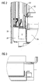
- FIG 2 and 3 are enlarged views of the circular sections II and III shown in FIG 1
- the cooking oven 10 comprises a cabinet 12 defining an oven cavity 14.
- the oven cavity 14 has a charging opening 1 for charging and discharging food-items to be cooked into and out of the oven cavity 14.
- the cooking oven 10 comprises a door 18 for opening and closing the charging opening 16.
- the door 18 has a front wall 20 with a handle 21 and a back wall 22, which faces the oven cavity 14.
- the door 18 is formed as a drawer-like door, which can be opened and closed in a substantially horizontal direction.
- the door 18 is attached to the free ends of two sliding bars 24, which are received in two corresponding guiding rails 26 arranged beneath the oven cavity 14. Accordingly, the door 18 may perform a horizontal back and forth movement together with the sliding bars 24, which slide along the guiding rails 26.
- each of sliding bars 24 has a U-shaped cross-section, in which rollers (not shown) are received, and each of the guiding rails 26 has a U-shaped cross-section sized to receive a sliding bar 24 therein.
- the door 18 is attached to the top side of the sliding bars 24 in such a manner, that only the front wall 20 of the door 18 projects from the free ends of the sliding bars 24 with respect to their longitudinal extensions, whereas the front wall 20 serves as a screen for covering the sliding bars 24 and guiding rails 26 when the cooking oven 10 is viewed from the front. Accordingly, such an arrangement of the door 18 on top of the sliding bars 24 does not increase the length of the sliding bars 24 in contrast to a structure, where the door is fixed to the front side of the sliding bars. Accordingly, the installation space for the sliding bars 24 within the cabinet 12 of the oven can be optimally exploited.
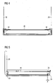
- FIG 4 is an enlarged front view
- FIG 5 is an enlarged side view of the cooking oven 10 shown in FIG 1 , whereas the cabinet 12 and the door 18 are omitted for illustrative purposes.
- the fins 28 extend upwards from the sliding bars 24 in such a manner, that the door 18 can be easily plugged on the fins 28 in order to firmly attach the door 18 at the sliding bars 24.
- a sealing gasket 32 is fixed to the cabinet 12 around the charging opening 16 in order to provide a sealing between the back wall 22 of the door 18 and the oven cavity 14.
- the sealing gasket 32 shall prevent, that moisture generated during a cooking procedure can escape from the inside of the oven cavity 14.
- a door closing force needs to be provided in order to press the back wall 22 of the door 18 tightly against the sealing gasket to achieve a proper functioning of the sealing gasket 32.
- This door closing force is generated by means of magnets 34, which are arranged at the rearmost end of guiding rails 26 and cooperate - when the door 18 is located in its closed position - with the rearmost free ends of the sliding bars 24 made of a magnetic material (magnetic components).
- the magnets 34 and the rearmost free ends of the sliding bars 24 are spaced from each other by a predetermined distance d, e.g. 0,5 to 2 mm.
- This distance d ensures a silent closing of the door 18, because the sliding bars 24 will not abut against the magnets 34.
- the distance d eliminates the possibility, that the sliding bars 24 abut against the magnets 34 before the back wall 22 properly engages the sealing gasket 32 in order to guarantee the required sealing performance.
- the door closing force provided by the magnets depends on the magnetic strength, the size and the number of the magnets 34, which are provided for this reason. Thus, the required closing force can be easily adjusted to different cooking oven designs.
- two attenuation means 36 are provided, which are described in more detail below with reference to FIG 6 to 8 .
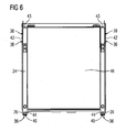
- FIG 6 is an enlarged top view of the cooking oven 10 shown in FIG 1 in the closed state of the door 18
- FIG.7 is an enlarged top view of the cooking oven 10 shown in FIG 1 in the opened state of the door 18, whereas the illustration of the cabinet 12 is omitted in FIG 6 and 7
- FIG 8 is an enlarged view of the circular section VIII in FIG 7 .
- Each of the attenuation means 36 comprises a stationary element 38 and a movable element 40.
- Each stationary element 38 is made of a metal or plastic material and includes a spring-like elastic leg 42.
- One end of the elastic leg 42 is fixed above an outer leg of a corresponding U-shaped guiding rail 26 at a position close to the front end of the guiding rail 26 in such a manner, that the elastic leg 42 extends to the front side of the cooking oven 10 in an angle ⁇ with respect to the guiding rail 42.
- the elastic 42 leg increasingly projects from the outer leg of the corresponding U-shaped guiding rail 26 towards its free end 43. This free end of the elastic leg 42 is bent inwardly in order to create a stopper, as it will be explained below.
- Each movable element 40 is fixed on top of the rearmost end of one of the sliding bars 24. Accordingly. The movable elements 40 follow the movements of the sliding bars 24.
- Each of the movable elements 40 comprises a brake shoe 44 made of a plastic material, which is arranged at the same height as the elastic leg 42 of the stationary element 38.
- a panel sheet 46 is fixed on the sliding bars 24, which also reinforces the structure of the sliding bars 24 and their relative position to each other.
- the structure of the sliding bars and the guiding rails is not limited to the one described above.
- the guiding rails may be inclined downwards towards the backside of the oven, as it is described in DE-A-102 53 158 -
- additional closing means may be provided, which generate a force contributing to the closing force of the door.
- Such additional closing means may comprise a spring-like element as the one disclosed in DE-U-20 2007 007 450 .
- more or less than two attenuating means can be provided.
Landscapes
- Engineering & Computer Science (AREA)
- Chemical & Material Sciences (AREA)
- Combustion & Propulsion (AREA)
- Mechanical Engineering (AREA)
- General Engineering & Computer Science (AREA)
- Baking, Grill, Roasting (AREA)
Abstract
Description
- The present invention relates to a cooking oven comprising a cabinet defining an oven cavity with a charging opening for charging the oven cavity with foodstuff to be cooked; a drawer-like door for optionally opening and closing said charging opening in a substantially horizontal direction; and a sealing gasket arranged between the door and the oven cavity.
- Cooking ovens of the above-mentioned type are already known. One problem to be solved with respect to such cooking ovens is to provide - in the closed state of the door - a tight sealing between the door and the cabinet by means of the sealing gasket in order to prevent the escape of moisture generated within the oven cavity during cooking procedures. Accordingly, a door closing force needs to be provided, which is high enough to guarantee a proper functioning of the sealing gasket.
- One possible solution with respect to the above-mentioned problem is disclosed in
DE-U-20 2007 007 450 , which describes a cooking oven comprising a cabinet defining an oven cavity with a charging opening for charging the oven cavity with foodstuff to be cooked; a drawer-like door for optionally opening and closing said charging opening in a substantially horizontal direction; and a sealing gasket arranged between the door and the oven cavity. The door is fixed to sliding bars, which slide in guiding rails in order to realize the horizontal opening and closing movement of the door. A closing device generating a closing force for closing the door is arranged at the guiding rails, which cooperates with the slide bars. This closing device comprises spring elements fixed to the rearmost portions of the guiding rails. These spring elements draw the slide bars at the end of their closing movement towards the back wall of the cabinet in order to press the inner wall of the door with a predetermined closing force against the sealing gasket, which is arranged around the charging opening of the cabinet. To ensure a smooth closing of the door, the cooking oven further comprises an attenuating means or damper, which counteracts the closing force of the closing device. - There is a general problem with respect to cooking ovens, in that the depth of the cabinet is limited due to installation space standardization and the tendency of downsizing the installation space of cooking ovens. Thus, the extraction length of drawer-like doors for their opening movement is also limited. Nevertheless, the extraction length of the door should be as long as possible in order to ensure a comfortable handling with respect to the charging and discharging of the oven cavity.
- However, according to
DE-U-20 2007 007 450 , the extraction length of the door is shortened due to the fact, that the closing device is arranged between the back wall of the cabinet and the sliding bars. Moreover, since the installation space of the closing device is in turn limited due to a minimum extraction length of the door, it may happen, that the closing device cannot guarantee a closing force, which is strong enough to ensure a proper functioning of the sealing gasket, in particular when an attenuation means is provided, which counteracts the closing force of the closing device. - An alternative proposal for increasing the closing force of an oven door is disclosed in
DE-A-102 53 158 describing a cooking oven comprising a cabinet defining an oven cavity with a charging opening for charging the oven cavity with foodstuff to be cooked; a drawer-like door for optionally opening and closing said charging opening in an substantially horizontal direction; and a sealing gasket arranged between the door and the oven cavity. The door is fixed to sliding bars, which slide in guiding rails in order to realize the horizontal opening and closing movement of the door. The guiding rails are inclined towards their rearmost free end in a downward direction relative to the horizontal, i.e. downwards towards the back of the oven, such that the self-weight of the door contributes to the door closing force when closing the door. However, also this arrangement cannot always guarantee a proper functioning of the sealing. - Starting from the above mentioned prior art technology it is an object of the present invention to provide a cooking oven of the mentioned type, which has an alternative configuration in order to eliminate one or more of the foregoing drawbacks.
- This object is solved by providing a cooking oven according to claim 1. The dependent claims refer to individual embodiments of the present invention.
- The present invention provides a cooking oven comprising a cabinet defining an oven cavity with a charging opening for charging the oven cavity with foodstuff to be cooked; a drawer-like door for optionally opening and closing said charging opening in a substantially horizontal direction; and a sealing gasket arranged between the door and the cabinet for sealing the cavity in the closed state of the door. According to the present invention, the cooking oven further comprises at least one magnet, which cooperates with at least one magnetic component of the cooking oven and is arranged in such a manner that it contributes to a closing force of the door in its closed state in order to assure a proper functioning of the sealing gasket. Compared with the closing device according to
DE-U-20 2007 007 450 magnets do not require as much installation space, which is advantageous with respect to the extraction length of the drawer-like door. Moreover, the strength and the number of the magnets can be easily adapted to the closing force of individual oven door designs, which is necessary for assuring a proper functioning of the sealing gasket. This adjustability of the door closing force is also advantageous with respect to the solution ofDE A 102 53 158 . - According to one preferred aspect of the present invention, the at least one magnet is a permanent magnet. However, electromagnets could be used as well.
- Preferably the at least one magnet - in the closed state of the door - is spaced from the cooperating magnetic component by a predetermined distance. Such a distance between the at least one magnet and the cooperating component ensures a silent closing operation of the door, because there will be no noise generated due to an abutment of these elements. Moreover, when a certain distance between the at least one magnet and the cooperating component is maintained in the closed state of the door, these elements cannot form a stopper with respect to the closing movement of the door, which could interfere with a proper sealing of the door by means of the sealing gasket. Preferably the distance is at least 0,5 to 2 mm.
- According to a preferred aspect of the present invention, the door is fixed to sliding bars, which slide in guiding rails in order to realize the essentially horizontal opening and closing movement of the door. Advantageously, the door is fixed to the sliding bars in such a manner, that it substantially does not project from the sliding bars with respect to their longitudinal extension. For example, the door may be substantially arranged on the sliding bars, such that only the front wall of the door projects from the sliding bars with respect to their longitudinal extension to form a screen in order to achieve a nice appearance of the cooking oven. By way of such a construction, the extension length of the drawer-like door is substantially not decreased in contrast to a construction, where the door is fixed to the front of the sliding bars.
- In order to fix the door to the sliding bars in the above-described manner, at least one fin for receiving the door is preferably fixed to the end of each sliding bar, such that it projects upwards in a direction substantially at right angle to the longitudinal extension of the corresponding sliding bar. Accordingly, the door may be fixed to the fins by means of a plug-in connection or the like.
- Moreover, the cooking oven according to the present invention may have one or more additional closing means generating a closing force, which contributes to the closing force of the door achieved by the magnets.
- For example, each of the guiding rails may be at least partially inclined towards its rearmost free end in a downward direction relative to the horizontal, such that the self-weight of the door contributes to the closing force achieved by the magnets.
- As an alternative or in addition, a closing means may be provided comprising a spring-like element, which draws the door in its closed position.
- Moreover, at least one attenuating means or damper is preferably provided, which attenuates the substantially horizontal opening and/or closing movement of the door in order to achieve a smooth operation thereof.
- According to a preferred aspect of the present invention, the at least one attenuating means comprises a stationary element and a movable element, which are moved relative to each other, when the door is opened or closed. The stationary element preferably comprises a spring-like leg and the movable element is formed as a break shoe, which displaces the spring-like leg bit by bit during the relative movement of the elements. This arrangement can be realized as a simple construction with little installation room. The stationary element may comprise a stopper for stopping the relative movement of the elements, in particular when the attenuating means is provided for damping the last part of the opening movement of the door.
- According to a preferred embodiment of the present invention, the sealing gasket serves as the only stopper for limiting the closing movement of the drawer-like door. This ensures, that the closing movement of the door is not stopped by means of another stopper before the proper functioning of the sealing gasket is achieved.
- Finally, a panel sheet is preferably provided between the sliding bars in order to receive foodstuff and/or fluids falling from baking trays, which are arranged above the panel sheet.
- The detailed configuration, features and advantages of the present invention will become apparent in the course of the following description with reference to the accompanying drawings
- FIG 1
- is a sectional side view showing a cooking oven according to one embodiment of the present invention, whereas the outet housing of the cooking oven is removed for better illustration
- FIG 2
- is an enlarged view of the circular section II shown in
FIG 1 - FIG 3
- is an enlarged view of the circular section III shown in
FIG 1 - FIG 4
- is an enlarged front view of the oven shown in
FIG 1 , whereas the main part of the cabinet and the door are omitted in order to illustrate fins for receiving the door - FIG 5
- is a side view of the arrangement shown in
FIG 4 - FIG 6
- is an enlarged top view of the cooking oven shown in
FIG 5 in the closed state of the door, whereas the cabinet is omitted for better illustration - FIG 7
- is an enlarged top view of the cooking oven shown in
FIG 5 in the opened state of the door, whereas the cabinet is omitted for better illustration and - FIG 8
- is an enlarged view of the circular section VIII in
FIG 7 - Below, one embodiment of the present will be described with reference to the figures. In the figures, like parts or portions are denoted by like reference numerals, and redundant descriptions will be omitted.
-
FIG 1 is a sectional side view of an embodiment of acooking oven 10 according to the present invention, andFIG 2 and 3 are enlarged views of the circular sections II and III shown inFIG 1 . Thecooking oven 10 comprises acabinet 12 defining anoven cavity 14. Theoven cavity 14 has a charging opening 1 for charging and discharging food-items to be cooked into and out of theoven cavity 14. Moreover, thecooking oven 10 comprises adoor 18 for opening and closing the charging opening 16. Thedoor 18 has afront wall 20 with ahandle 21 and aback wall 22, which faces theoven cavity 14. Moreover, thedoor 18 is formed as a drawer-like door, which can be opened and closed in a substantially horizontal direction. In this regard, thedoor 18 is attached to the free ends of two slidingbars 24, which are received in two corresponding guiding rails 26 arranged beneath theoven cavity 14. Accordingly, thedoor 18 may perform a horizontal back and forth movement together with the slidingbars 24, which slide along the guiding rails 26. In this regard, each of slidingbars 24 has a U-shaped cross-section, in which rollers (not shown) are received, and each of the guiding rails 26 has a U-shaped cross-section sized to receive a slidingbar 24 therein. - As it is best shown in
FIG 2 , thedoor 18 is attached to the top side of the slidingbars 24 in such a manner, that only thefront wall 20 of thedoor 18 projects from the free ends of the slidingbars 24 with respect to their longitudinal extensions, whereas thefront wall 20 serves as a screen for covering the slidingbars 24 and guidingrails 26 when thecooking oven 10 is viewed from the front. Accordingly, such an arrangement of thedoor 18 on top of the slidingbars 24 does not increase the length of the slidingbars 24 in contrast to a structure, where the door is fixed to the front side of the sliding bars. Accordingly, the installation space for the slidingbars 24 within thecabinet 12 of the oven can be optimally exploited. For fixing thedoor 18 to the top-side of the slidingbars 24,fins 28 are attached to the front ends of the slidingbars 24 by means of weldingbolts 30, as it is shown inFIG 4 and 5. FIG 4 is an enlarged front view andFIG 5 is an enlarged side view of thecooking oven 10 shown inFIG 1 , whereas thecabinet 12 and thedoor 18 are omitted for illustrative purposes. Thefins 28 extend upwards from the slidingbars 24 in such a manner, that thedoor 18 can be easily plugged on thefins 28 in order to firmly attach thedoor 18 at the sliding bars 24. - A sealing
gasket 32 is fixed to thecabinet 12 around the charging opening 16 in order to provide a sealing between theback wall 22 of thedoor 18 and theoven cavity 14. The sealinggasket 32 shall prevent, that moisture generated during a cooking procedure can escape from the inside of theoven cavity 14. In this regard, a door closing force needs to be provided in order to press theback wall 22 of thedoor 18 tightly against the sealing gasket to achieve a proper functioning of the sealinggasket 32. This door closing force is generated by means ofmagnets 34, which are arranged at the rearmost end of guidingrails 26 and cooperate - when thedoor 18 is located in its closed position - with the rearmost free ends of the slidingbars 24 made of a magnetic material (magnetic components). Themagnets 34 and the rearmost free ends of the slidingbars 24 are spaced from each other by a predetermined distance d, e.g. 0,5 to 2 mm. This distance d ensures a silent closing of thedoor 18, because the slidingbars 24 will not abut against themagnets 34. Moreover, the distance d eliminates the possibility, that the slidingbars 24 abut against themagnets 34 before theback wall 22 properly engages the sealinggasket 32 in order to guarantee the required sealing performance. The door closing force provided by the magnets depends on the magnetic strength, the size and the number of themagnets 34, which are provided for this reason. Thus, the required closing force can be easily adjusted to different cooking oven designs. - In order to achieve a smooth movement of the
door 18 at the end of the opening procedure, two attenuation means 36 (damper) are provided, which are described in more detail below with reference toFIG 6 to 8 . -
FIG 6 is an enlarged top view of thecooking oven 10 shown inFIG 1 in the closed state of thedoor 18,FIG.7 is an enlarged top view of thecooking oven 10 shown inFIG 1 in the opened state of thedoor 18, whereas the illustration of thecabinet 12 is omitted inFIG 6 and7 , andFIG 8 is an enlarged view of the circular section VIII inFIG 7 . - Each of the attenuation means 36 comprises a
stationary element 38 and amovable element 40. - Each
stationary element 38 is made of a metal or plastic material and includes a spring-likeelastic leg 42. One end of theelastic leg 42 is fixed above an outer leg of a corresponding U-shaped guidingrail 26 at a position close to the front end of the guidingrail 26 in such a manner, that theelastic leg 42 extends to the front side of thecooking oven 10 in an angle α with respect to the guidingrail 42. Accordingly, the elastic 42 leg increasingly projects from the outer leg of the corresponding U-shaped guidingrail 26 towards itsfree end 43. This free end of theelastic leg 42 is bent inwardly in order to create a stopper, as it will be explained below. - Each
movable element 40 is fixed on top of the rearmost end of one of the sliding bars 24. Accordingly. Themovable elements 40 follow the movements of the sliding bars 24. Each of themovable elements 40 comprises abrake shoe 44 made of a plastic material, which is arranged at the same height as theelastic leg 42 of thestationary element 38. - Thus, when the sliding
bars 24 are moved relative to the guiding rails 26, thebrake shoe 44 and theelastic leg 42 come into engagement with each other shortly before the door reaches its fully opened position. In this process, thebrake shoe 44 pushes theelastic leg 42 to the outside, whereby a friction force is generated, which slows down the movement of thedoor 18. Due to the arrangement of theelastic leg 42 at the angle α, this friction force increases while thedoor 18 approaches its fully opened position, until the breakingshoe 44 reaches the fully opened position of thedoor 18 defined by the inwardly bentfree end 43 of theelastic leg 42, which acts as a stopper. - In order to receive foodstuff or liquids falling from baking trays or baking grids arranged within the
oven cavity 14, apanel sheet 46 is fixed on the slidingbars 24, which also reinforces the structure of the slidingbars 24 and their relative position to each other. - It should be noted, that the structure of the sliding bars and the guiding rails is not limited to the one described above. In particular, the guiding rails may be inclined downwards towards the backside of the oven, as it is described in
DE-A-102 53 158 - Moreover, additional closing means may be provided, which generate a force contributing to the closing force of the door. Such additional closing means may comprise a spring-like element as the one disclosed inDE-U-20 2007 007 450 . In addition, more or less than two attenuating means can be provided. - Although only one exemplary embodiment of this invention has been described in detail above, those skilled in the art will readily appreciate that many modifications are possible with respect to the exemplary embodiments without materially departing from the novel teachings and advantages of this invention. Accordingly, all such modifications are intended to be included within the scope of this invention.
-
- 10
- cooking oven
- 12
- cabinet
- 14
- oven cavity
- 16
- charging opening
- 18
- door
- 20
- front wall
- 21
- handle
- 22
- back wall
- 24
- sliding bar
- 26
- guiding rail
- 28
- fin
- 30
- welding bolt
- 32
- sealing gasket
- 34
- magnet
- 36
- attenuating means
- 38
- stationary element
- 40
- movable element
- 42
- leg
- 43
- free end
- 44
- brake shoe
- 46
- panel sheet
- d
- distance
- α
- angle
Claims (12)
- A cooking oven (10) comprising a cabinet (12) defining an oven cavity (14) with a charging opening (16) for charging the oven cavity (14) with foodstuff to be cooked; a drawer-like door (18) for optionally opening and closing said charging opening (16) in a substantially horizontal direction; and a sealing gasket (32) arranged between the door (18) and the cabinet (12) for sealing the oven cavity (14) in the closed state of the door (18); characterized in that the cooking oven (10) comprises at least one magnet (34), which cooperates with at least one magnetic component (24) of the cooking oven (10) and is arranged in such a manner that it contributes to a closing force of the door (18) in its closed state in order to assure a proper functioning of the sealing gasket (32).
- A cooking oven (10) according to claim 1, characterized in that the at least one magnet (34) is a permanent magnet.
- A cooking oven (10) according to one of the preceding claims, characterized in that the at least one magnet (34), in the closed state of the door (18), is spaced apart from the cooperating magnetic component (24) by a predetermined distance (d).
- A cooking oven (10) according to claim 3, characterized in that the distance (d) is at least 0,5 to 2 mm.
- A cooking oven (10) according to one of the preceding claims, characterized in that the door (18) is fixed to sliding bars (24), which slide in guiding rails (26).
- A cooking oven (10) according to claim 5, characterized in that the door (18) is fixed to the sliding bars (24) in such a manner, that it substantially does not project from the sliding bars (24) with respect to their longitudinal extension.
- A cooking oven (10) according to claim 6, characterized in that at least one fin (28) for receiving the door (18) is fixed to the end of each sliding bar (24), such that it projects upwards in a direction substantially at right angle to the longitudinal extension of the corresponding sliding bar (24).
- A cooking oven (10) according to one of claims 5 to 7, characterized in that each of the guiding rails (26) is at least partially inclined towards its rearmost free end in a downward direction relative to the horizontal.
- A cooking oven (10) according to one of claims 5 to 8, characterized in that a panel sheet (46) is provided between the sliding bars (24).
- A cooking oven (10) according to one of the preceding claims, characterized in that at least one further closing means is provided generating a force, which contributes to the closing force of the door (18), wherin preferably the at least one further closing means comprises a spring-like element.
- A cooking oven (10) according to one of the preceding claims, characterized in that at least one attenuating means (36) is provided, which attenuates the substantially horizontal opening and/or closing movement of the door (18), wherin preferably the at least one attenuating means (36) comprises a stationary element (38) and a movable element (40), which are moved relative to each other, when the door (18) is opened or closed and/or wherin preferably the stationary element (38) comprises a spring-like leg (42) and the movable element (40) is formed as a break shoe (44), which displaces the spring-like leg (42) bit by bit during the relative movement of the elements (38, 40) and/or wherin preferably the stationary element (38) comprises a stopper (43) for stopping the relative movement of the elements (38, 40).
- A cooking oven (10) according to one of the preceding claims, characterized in that the sealing gasket (32) further serves as a stopper for limiting the closing movement of the drawer-like door (18).
Priority Applications (1)
| Application Number | Priority Date | Filing Date | Title |
|---|---|---|---|
| EP08003178A EP2093498A1 (en) | 2008-02-21 | 2008-02-21 | Cooking oven |
Applications Claiming Priority (1)
| Application Number | Priority Date | Filing Date | Title |
|---|---|---|---|
| EP08003178A EP2093498A1 (en) | 2008-02-21 | 2008-02-21 | Cooking oven |
Publications (1)
| Publication Number | Publication Date |
|---|---|
| EP2093498A1 true EP2093498A1 (en) | 2009-08-26 |
Family
ID=39572756
Family Applications (1)
| Application Number | Title | Priority Date | Filing Date |
|---|---|---|---|
| EP08003178A Withdrawn EP2093498A1 (en) | 2008-02-21 | 2008-02-21 | Cooking oven |
Country Status (1)
| Country | Link |
|---|---|
| EP (1) | EP2093498A1 (en) |
Citations (10)
| Publication number | Priority date | Publication date | Assignee | Title |
|---|---|---|---|---|
| DE2036827A1 (en) * | 1970-07-24 | 1972-01-27 | Siemens Elektrogeraete Gmbh | Oven and roasting tube |
| JPH02309135A (en) | 1989-05-23 | 1990-12-25 | Matsushita Electric Ind Co Ltd | Opening or closing device for door of cooking apparatus |
| EP0443329A2 (en) * | 1990-02-21 | 1991-08-28 | BOSCH-SIEMENS HAUSGERÄTE GmbH | Baking oven |
| DE9211953U1 (en) * | 1992-09-04 | 1992-10-22 | Bosch-Siemens Hausgeräte GmbH, 8000 München | Device for an oven muffle |
| EP1420210A1 (en) * | 2002-11-14 | 2004-05-19 | BSH Bosch und Siemens Hausgeräte GmbH | Cooking oven |
| DE10253158A1 (en) | 2002-11-14 | 2004-05-27 | BSH Bosch und Siemens Hausgeräte GmbH | Horizontal guide system for tray used with baking oven to support dishes has rods with rollers engaging in horizontal guide rails |
| JP2006308253A (en) * | 2005-04-28 | 2006-11-09 | Matsushita Electric Ind Co Ltd | Cooker |
| JP2007139248A (en) * | 2005-11-16 | 2007-06-07 | Matsushita Electric Ind Co Ltd | Gas cooker |
| DE202007007450U1 (en) | 2007-05-25 | 2007-08-02 | BSH Bosch und Siemens Hausgeräte GmbH | Retract absorption equipment e.g. for oven, has area having drawer-like lockable door and which is rigidly fastened to pair of sliding courses |
| JP2008025903A (en) | 2006-07-20 | 2008-02-07 | Toshiba Corp | Cooker |
-
2008
- 2008-02-21 EP EP08003178A patent/EP2093498A1/en not_active Withdrawn
Patent Citations (10)
| Publication number | Priority date | Publication date | Assignee | Title |
|---|---|---|---|---|
| DE2036827A1 (en) * | 1970-07-24 | 1972-01-27 | Siemens Elektrogeraete Gmbh | Oven and roasting tube |
| JPH02309135A (en) | 1989-05-23 | 1990-12-25 | Matsushita Electric Ind Co Ltd | Opening or closing device for door of cooking apparatus |
| EP0443329A2 (en) * | 1990-02-21 | 1991-08-28 | BOSCH-SIEMENS HAUSGERÄTE GmbH | Baking oven |
| DE9211953U1 (en) * | 1992-09-04 | 1992-10-22 | Bosch-Siemens Hausgeräte GmbH, 8000 München | Device for an oven muffle |
| EP1420210A1 (en) * | 2002-11-14 | 2004-05-19 | BSH Bosch und Siemens Hausgeräte GmbH | Cooking oven |
| DE10253158A1 (en) | 2002-11-14 | 2004-05-27 | BSH Bosch und Siemens Hausgeräte GmbH | Horizontal guide system for tray used with baking oven to support dishes has rods with rollers engaging in horizontal guide rails |
| JP2006308253A (en) * | 2005-04-28 | 2006-11-09 | Matsushita Electric Ind Co Ltd | Cooker |
| JP2007139248A (en) * | 2005-11-16 | 2007-06-07 | Matsushita Electric Ind Co Ltd | Gas cooker |
| JP2008025903A (en) | 2006-07-20 | 2008-02-07 | Toshiba Corp | Cooker |
| DE202007007450U1 (en) | 2007-05-25 | 2007-08-02 | BSH Bosch und Siemens Hausgeräte GmbH | Retract absorption equipment e.g. for oven, has area having drawer-like lockable door and which is rigidly fastened to pair of sliding courses |
Similar Documents
| Publication | Publication Date | Title |
|---|---|---|
| CN111328361B (en) | Flap fitting for furniture, side wall of a furniture body and furniture having a side wall | |
| EP2035640B1 (en) | Domestic appliance with concealed hinge | |
| JP5373071B2 (en) | sliding door | |
| US10165859B2 (en) | Refrigerator appliance with a drawer slide synchronizer | |
| US9897327B2 (en) | Anti-spill oven door vents | |
| EP2397636A1 (en) | Latch apparatus | |
| KR102101579B1 (en) | Air tight door | |
| CN101433409A (en) | Controlled closure system for sliding furniture elements | |
| JP2020530370A (en) | Drawer guide | |
| EP2687786A2 (en) | Assembly of a door hinge of an oven of a household appliance with dampened closing | |
| KR20160065725A (en) | Fixing apparatus for sliding rail | |
| JP2011089738A (en) | Heating cooker | |
| CN111344470A (en) | Door hinge for oven | |
| CN103002777B (en) | Pull-out guide for furniture or household appliances | |
| AU2010288949B2 (en) | Snap arm unit for a door interlocking device | |
| EP3009693B1 (en) | Fixing system for one groove-shaped crosspiece to a piece of furniture | |
| KR102057501B1 (en) | A Floor Sealing Device For Doors | |
| JP5072772B2 (en) | Grill unit and heating cooker provided with the same | |
| CN109419192B (en) | Slide rail assembly and slide rail installation method | |
| EP1571285A3 (en) | Security frame with sliding armour-plate on the shutter for windows, doors or the like | |
| EP2395185A1 (en) | Appliance, such as a domestic oven | |
| CN107485197A (en) | It is incubated drawer | |
| JP7810587B2 (en) | Drawer structure | |
| CN102245987B (en) | Refrigerating device with telescopic pull-out mechanism | |
| EP0337962A1 (en) | Heat-guard for the control on the front panel of a cooking oven |
Legal Events
| Date | Code | Title | Description |
|---|---|---|---|
| PUAI | Public reference made under article 153(3) epc to a published international application that has entered the european phase |
Free format text: ORIGINAL CODE: 0009012 |
|
| 17P | Request for examination filed |
Effective date: 20090331 |
|
| AK | Designated contracting states |
Kind code of ref document: A1 Designated state(s): AT BE BG CH CY CZ DE DK EE ES FI FR GB GR HR HU IE IS IT LI LT LU LV MC MT NL NO PL PT RO SE SI SK TR |
|
| AX | Request for extension of the european patent |
Extension state: AL BA MK RS |
|
| AKX | Designation fees paid |
Designated state(s): AT BE BG CH CY CZ DE DK EE ES FI FR GB GR HR HU IE IS IT LI LT LU LV MC MT NL NO PL PT RO SE SI SK TR |
|
| RAP1 | Party data changed (applicant data changed or rights of an application transferred) |
Owner name: ELECTROLUX HOME PRODUCTS CORPORATION N.V. |
|
| RAP1 | Party data changed (applicant data changed or rights of an application transferred) |
Owner name: ELECTROLUX HOME PRODUCTS CORPORATION N.V. |
|
| STAA | Information on the status of an ep patent application or granted ep patent |
Free format text: STATUS: THE APPLICATION IS DEEMED TO BE WITHDRAWN |
|
| 18D | Application deemed to be withdrawn |
Effective date: 20130829 |