EP2093084A1 - Condensate draining pipe for a heating, ventilating and/or air conditioning system and method for assembling a condensate draining pipe - Google Patents
Condensate draining pipe for a heating, ventilating and/or air conditioning system and method for assembling a condensate draining pipe Download PDFInfo
- Publication number
- EP2093084A1 EP2093084A1 EP08003328A EP08003328A EP2093084A1 EP 2093084 A1 EP2093084 A1 EP 2093084A1 EP 08003328 A EP08003328 A EP 08003328A EP 08003328 A EP08003328 A EP 08003328A EP 2093084 A1 EP2093084 A1 EP 2093084A1
- Authority
- EP
- European Patent Office
- Prior art keywords
- condensate
- draining pipe
- vehicle
- fitting
- condensate draining
- Prior art date
- Legal status (The legal status is an assumption and is not a legal conclusion. Google has not performed a legal analysis and makes no representation as to the accuracy of the status listed.)
- Granted
Links
Images



Classifications
-
- B—PERFORMING OPERATIONS; TRANSPORTING
- B60—VEHICLES IN GENERAL
- B60H—ARRANGEMENTS OF HEATING, COOLING, VENTILATING OR OTHER AIR-TREATING DEVICES SPECIALLY ADAPTED FOR PASSENGER OR GOODS SPACES OF VEHICLES
- B60H1/00—Heating, cooling or ventilating devices
- B60H1/32—Cooling devices
- B60H1/3233—Cooling devices characterised by condensed liquid drainage means
-
- B—PERFORMING OPERATIONS; TRANSPORTING
- B60—VEHICLES IN GENERAL
- B60H—ARRANGEMENTS OF HEATING, COOLING, VENTILATING OR OTHER AIR-TREATING DEVICES SPECIALLY ADAPTED FOR PASSENGER OR GOODS SPACES OF VEHICLES
- B60H1/00—Heating, cooling or ventilating devices
- B60H1/00507—Details, e.g. mounting arrangements, desaeration devices
- B60H1/00557—Details of ducts or cables
-
- Y—GENERAL TAGGING OF NEW TECHNOLOGICAL DEVELOPMENTS; GENERAL TAGGING OF CROSS-SECTIONAL TECHNOLOGIES SPANNING OVER SEVERAL SECTIONS OF THE IPC; TECHNICAL SUBJECTS COVERED BY FORMER USPC CROSS-REFERENCE ART COLLECTIONS [XRACs] AND DIGESTS
- Y10—TECHNICAL SUBJECTS COVERED BY FORMER USPC
- Y10T—TECHNICAL SUBJECTS COVERED BY FORMER US CLASSIFICATION
- Y10T29/00—Metal working
- Y10T29/49—Method of mechanical manufacture
- Y10T29/49826—Assembling or joining
-
- Y—GENERAL TAGGING OF NEW TECHNOLOGICAL DEVELOPMENTS; GENERAL TAGGING OF CROSS-SECTIONAL TECHNOLOGIES SPANNING OVER SEVERAL SECTIONS OF THE IPC; TECHNICAL SUBJECTS COVERED BY FORMER USPC CROSS-REFERENCE ART COLLECTIONS [XRACs] AND DIGESTS
- Y10—TECHNICAL SUBJECTS COVERED BY FORMER USPC
- Y10T—TECHNICAL SUBJECTS COVERED BY FORMER US CLASSIFICATION
- Y10T29/00—Metal working
- Y10T29/49—Method of mechanical manufacture
- Y10T29/49826—Assembling or joining
- Y10T29/49908—Joining by deforming
Definitions
- the invention relates to a condensate draining pipe for a heating, ventilating and/or air conditioning (HVAC) system, for example, of a automotive vehicle and to a method for assembling a condensate draining pipe of a HVAC system.
- HVAC heating, ventilating and/or air conditioning
- the heating, ventilating and/or air conditioning system of, for example, an automotive vehicle typically includes a draining tray positioned underneath the evaporator to collect the condensate water which is formed on the evaporator during operation of the system.
- the condensate water which collects in the tray is drained away through a condensate draining hose which extends from the tray to a draining hole provided in, for example, the floor of the vehicle which communicates with the exterior.
- a condensate draining hose for a vehicle air-conditioning system which comprises a rigid portion which extends through the vehicle wall and a co-moulded elastomeric portion having an end portion shaped for connection to the tray of the air conditioning system is known from EP 1 645 447 B1 .
- this monolithic condensate draining hose has the disadvantage that it is complicated to fit into the vehicle.
- a condensate draining pipe for a heating, ventilating and/air conditioning system which comprises a condensate feed portion and a condensate drain portion.
- the condensate feed portion and the condensate drain portion are connectable to one another by a press-fit coupling assembly which comprises an O-ring seal.
- the condensate draining pipe comprises two pieces which, according to the invention, are connectable to one another by a press-fitting coupling assembly.
- a two-piece draining pipe has the advantage that the two pieces may be fitted into the vehicle at different stages in the assembly line. Therefore, a greater degree of flexibility is provided which can reduce the costs of producing the vehicle.
- a press-fit coupling has the advantage that the two pieces can be connected together by a simple press fitting procedure which can be performed without particular tools. This further simplifies the assembly of the condensate draining pipe in the vehicle.
- the O-ring seal is resilient and may comprise rubber, for example.
- the O-ring seal has the advantage that a detachable press-fit connection is provided.
- the condensate feed portion and the condensate drain portion of the condensate draining pipe may detachedly connected to one another which simplifies maintenance and repair of the HVAC system.
- the O-ring seal provides a cylindrical interference fit between the two pieces of the condensate draining pipe.
- the press-fit coupling assembly comprises a shaft fitting and a sleeve flange fitting.
- the shaft fitting is able to be accommodated within the sleeve flange fitting.
- the press-fit coupling assembly is assembled so that the O-ring seal is compressed between an outer surface of the shaft fitting and an inner surface of the sleeve flange fitting.
- the shaft fitting is provided by an end of the condensate feed portion and comprises a nozzle shaped end of the condensate feed portion of the draining pipe.
- An end of the condensate draining portion may provide the sleeve flange fitting.
- the sleeve flange fitting is, in an embodiment, integral with the condensate drain portion which has the advantage of reducing the number of joints.
- the condensate feed portion may further comprise a feed flange which is adapted to be connected to a condensate drain flange of the HVAC module of the HVAC system.
- the condensate drain flange may be a portion of the draining tray of the HVAC.
- the feed flange of the condensate feed portion of the draining pipe may further comprise latching means for detachedly attaching the condensate feed portion to the condensate drain flange of the HVAC module.
- the latching means may comprise at least one opening positioned in the condensate feed portion for accommodating a resilient snap action hook protruding from the drain flange of the HVAC module.
- the condensate drain portion may further comprise a draining outlet nozzle through which the condensate is drained away.
- the condensate draining pipe further comprises a bushing adapted to accommodate the drain nozzle of the compensate drain portion.
- the bushing is adapted to hold the drain nozzle of the draining pipe in the opening positioned in the vehicle body panel.
- the bushing may also have a sound insulation as well as a sealing function.
- the sleeve flange fitting and/or the shaft fitting may comprise a groove for accommodating the O-ring seal.
- a groove has the advantage that the O-ring seal is held in the desired position within the press-fit coupling assembly. Furthermore, the cross-sectional area of the interface between the O-ring seal and the shaft fitting and sleeve flange fitting is increased which may further improve the reliability of the seal.
- the condensate draining pipe further comprises a height adjustment fixing.
- the fixing enables the draining pipe to be attached to another component in a desired position.
- the fixing may be provided in the form of a height adjustment fixing so that the position of the draining pipe may be adjusted so as to allow for variations in manufacturing tolerance.
- the height adjustment fixing comprises a slot fixing.
- the height adjustment fixing is attached to the condensate draining portion and, in a further embodiment, is attached to the sleeve flange.
- the condensate feed portion is flexible and the condensate draining portion and the shaft fitting are rigid.
- the condensate drain portion may be pre-assembled into the vehicle and the condensate feed portion fitted afterwards.
- the flexibility of the condensate feed portion can be useful during the fitting when arranging the condensate feed portion in position and connecting it to the pre-mounted condensate drain portion by the press-fit coupling assembly.
- the condensate feed portion comprises a flexible compensating portion arranged adjacent the press-fit coupling assembly.
- the flexible portion may be provided by a portion of the pipe having a bellows form. This enables differences in the size and arrangement of the condensate draining pipe to be compensated so that the two separate pieces of the condensate draining pipe can be fitted together and a sealed joint be provided by the press-fit coupling assembly.
- the resilient O-ring is compressed between the rigid shaft fitting and the rigid sleeve flange fitting of the condensate draining portion to provide a seal and a detachable press-fit between the condensate feed portion and the condensate draining portion of the draining pipe.
- the condensate feed portion and condensate drain portion of the draining pipe may each have a form which is adapted to fit a desired route of the draining pipe within the vehicle.
- Each portion has a tubular form.
- the cross-section of each portion is not necessarily circular and may vary along the length in order that the condensate draining pipe is better adapted to the available space.
- the two portions may also have a form and length so that the press-fit coupling assembly through which the two portions are connected to one another is arranged in a particular location within the vehicle. This location can be chosen so as to simplify the fitting of the draining pipe into the vehicle.
- the condensate feed portion extends between the HVAC module and a centre console of the vehicle.
- the condensate drain portion extends from the centre console centre console the vehicle to an opening in the body panel of the vehicle through which the condensate can drain away to the exterior.
- the coupling assembly is, therefore, arranged in the region of the centre console of the vehicle.
- the condensate drain portion is integral with a portion of the vehicle bodywork. This has the advantage that the space occupied by the condensate drain portion of the draining pipe can be more closely adapted to the form of the vehicle bodywork. Therefore, it is possible to arrange the condensate drain portion so as to be less visually noticeable.
- the condensate drain portion may be an integral part of a cast or injection moulded portion of the vehicle bodywork. A section of the condensate drain portion may be integral with a foot well or with the centre console of the vehicle, for example.
- the invention also provides a method for assembling a condensate draining pipe of a heating ventilating and/or air conditioning system, the condensate draining pipe comprising a condensate feed portion and a condensate drain portion connectable to one another by a press-fit coupling assembly.
- the condensate drain portion is mounted before the condensate feed portion is connected to the condensate drain portion by the press-fit coupling assembly.
- the condensate drain portion is, therefore, pre-mounted in, for example, the vehicle and the condensate feed portion may be mounted into the vehicle at a later stage in the assembly line.
- This has the advantage that sound insulation and/or carpet may be placed on top of the condensate drain portion rather than the draining pipe having to be inserted through a hole provided in the pre-fitted sound insulation and/or carpet in order that the pipe be fitted into the opening in the car bodywork.
- the condensate feed portion may be provided with a shaft fitting and the condensate drain portion may be provided with a sleeve flange.
- the shaft fitting is inserted into the sleeve flange fitting to provide the press-fit coupling assembly connecting the condensate drain portion and the condensate feed portion.
- an O-ring seal is provided and the press-fit coupling is sealed by positioning the O-ring seal between the shaft fitting and the sleeve flange fitting.
- the condensate feed portion may be connected to the condensate drain portion by compressing the O-ring seal between an outer surface of the shaft fitting and an inner surface of the sleeve flange fitting.
- the condensate drain portion may be pre-mounted by mounting it on a portion of the vehicle bodywork.
- the condensate drain portion can have a form and be positioned such that the press-fit coupling assembly is arranged at an edge of the sound insulation and/or carpet. Therefore, a one piece carpet without a hole or slot in the centre for the draining pipe may be used.
- the coupling assembly is arranged at the centre console of the vehicle, the sound insulation and/or carpet may include a cutout in its edge which abuts the centre console in which the sleeve flange of the condensate draining portion is exposed.
- Pre-mounting the draining portion of the draining pipe enables it to be hidden away under sound insulation and/or carpet therefore improving the visual look of the vehicle interior.
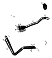
- Figures 1 to 3 illustrate the components of a condensate draining pipe according to a first embodiment of the invention.
- FIGs 1 and 2 illustrate the components of a condensate draining pipe 1 of a heating, ventilating and/or air conditioning (HVAC) system of an automotive vehicle according to a first embodiment of the invention.
- HVAC heating, ventilating and/or air conditioning
- the components are illustrated unassembled in figure 1 and assembled in figure 2 .
- the condensate draining pipe 1 comprises two separate pieces, a condensate feeding portion 2 and a condensate draining portion 3 each having a generally pipe form.
- the condensate feed portion 2 and the condensate draining portion 3 are connectable to one another by a coupling assembly 4 to provide the condensate draining pipe 1.
- the coupling assembly 4 provides a press-fit joint which enables the two separate portions 2, 3 of the condensate draining pipe 1 to be detachedly connected to one another.
- the coupling assembly 4 comprises a shaft fitting 5, an O-ring seal 6 and a sleeve flange fitting 7 and is illustrated in more detail in Figure 3 .
- the shaft fitting 5 is provided in the form of a tubular nozzle which forms an end of the condensate feed portion 2 of the condensate draining pipe 1.
- the nozzle has an outer diameter which is smaller than the outer diameter of the body of the condensate feed portion 2.
- the O-ring seal 6 is illustrated in figure 1 and 3b arranged around the outer surface of the nozzle 5 providing the shaft fitting 5.
- the sleeve flange fitting 7 is provided as a widened end 8 of the condensate draining portion 3.
- the sleeve flange fitting 7 and the shaft fitting 5 are rigid whereas the O-ring seal 6 is resilient.
- the sleeve flange fitting 7 and the shaft fitting 5 may be formed from a rigid plastic and the O-ring seal may be rubber.
- the shaft fitting 5 is accommodated within the sleeve flange fitting 7 at the distal end 8 of the condensate drain portion 3 such that the O-ring 6 is compressed between the outer surface of the shaft fitting 5 and the inner surface of the sleeve flange fitting 7.
- the sleeve flange fitting 7 also includes an annular groove 9 on its inner surface for accommodating the O-ring seal 6 when the coupling assembly 4 is in the assembled condition, as illustrated in Figure 3a
- the condensate draining pipe 1 further includes a height adjustment fitting 10 which extends from the sleeve flange fitting 4.
- the height adjustment fitting 10 is a slot fitting thus enabling the position of the condensate draining portion 3 to be adjusted.
- the opposing end 12 of the condensate feed portion 2 is adapted to be connected to the draining flange of a non-illustrated HVAC module.
- the condensate feed portion 2 includes a latching means 11 towards the opposing end 12 of the condensate feed portion 2. This latching means is provided in the form of an opening in which a resilient snap action hook of the HVAC module can be accommodated.
- the condensate feed portion 2 has a generally pipe form and includes a first bend through around 90° and a second bend of around 120° so that when the shaft fitting 5 is in a generally vertical direction, the opposing feed end 12 is in a generally horizontal position.
- the form of the condensate feed portion 2 is chosen so that it is accommodated in the desired position within the vehicle.
- the condensate drain portion 3 of the condensate draining pipe 1 also includes a number of bends and turns ending in a draining end 14 which is adapted to be accommodated in an opening positioned in a body panel of the vehicle.
- the condensate draining pipe 1 may further include a bushing 15 for coupling the draining end 14 with the opening in the vehicle body panel.
- the bushing 15 has a generally annular form. When assembled, the draining end 14 of the condensate drain portion 3 is accommodated in the through hole of the bushing 15.
- condensate from the HVAC module enters the condensate draining pipe 1 at the feed end 12 of the condensate feed portion 2, flows through the condensate feed portion 2, the coupling assembly 4 and the condensate drain portion 3 and exits the draining end 14 to flow to the exterior of the vehicle.
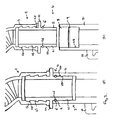
- FIG 3 illustrates the press-fit coupling assembly 4 in partial cross-sectional form.
- the shaft fitting 5 comprises a distal end portion 21 and annular protruding flange portion 22 and a connection portion 23 which comprises a plurality of annular ribs 24 protruding from the outer surface 25 of the shaft fitting 5.
- the annular protruding flange portion is positioned between the distal end portion 21 and the connection portion 23.
- the distal end portion 21 of the shaft fitting 5 further comprises an annular groove 26 adapted to accommodate the O-ring 6.
- the groove 26 and the O-ring 6 are positioned in the distal end 21 adjacent the annular flange 22.
- the shaft fitting 5 is connected to the body 13 of the condensate feed portion 2 by a radial compression fit between outside of the rigid connection portion 23 comprising the ribs 24 and the inside surface of the flexible material of the body portion 13 of the condensate feed portion 2 to provide a sealed connection.
- Figure 3a illustrates the press-fit coupling assembly 4 in the assembled condition.
- the O-ring 6 is compressed between the outer surface 27 of the shaft fitting 5 and the inner surface 28 of the sleeve flange fitting 7 to provide a seal.
- the O-ring 6 is positioned in the groove 9 and groove 26 of the sleeve flange fitting 7 and shaft fitting 5, respectively.
- the annular protruding flange 22 of the shaft fitting 5 is in contact with the distal end 8 of the sleeve flange fitting 7.
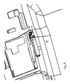
- the condensate drain portion 3 of the condensate drain pipe 1 is pre-mounted in the vehicle, as illustrated in Figure 4 .
- the condensate drain portion 3 extends between the centre console 16 of vehicle and an opening 17 positioned in the floor panel 18 of the vehicle.
- the bushing 15 couples the drain end 14 to the opening 17.
- Figure 4 also illustrates that the sleeve flange fitting 7 of the condensate drain portion 3 is fixed by the height adjustment fixing 10 to the centre console 16 of the vehicle.
- Figure 5 illustrates the fitting of sound insulation and carpet 19 in the vehicle.
- the sound insulation and carpet 19 is fitted over the condensate drain portion 3 of the condensate draining pipe 1 so that only the end of the sleeve flange fitting 7 is exposed.
- the remaining areas of the condensate draining portion 3 are covered by the sound insulation and carpet 19.
- the condensate feed portion 2 of the condensate draining pipe 1 is fitted.
- the feed end 12 of the condensate feed portion 2 may be first attached to the HVAC drain flange of the HVAC module and these connected components fitted into the vehicle.
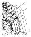
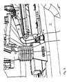
- FIGS 6 and 7 illustrate different views of the connection of the condensate feed portion 2 to the pre-mounted condensate drain portion by means of the press-fit coupling assembly 4.
- Figure 6 illustrates the feed flange end 12 of the condensate feed portion 2 of the condensate draining pipe 1.
- the resilient snap action hook 20 of the HVAC module is engaged with the opening 11 positioned in the feed end 12 of the condensate feed portion 3 as illustrated in Figure 7 .
- the shaft fitting 5 is press-fitted into the sleeve flange fitting 7 of the condensate drain portion 3.
- Figure 7 illustrates the connection of the shaft fitting 5 with the sleeve flange fitting 7. This is achieved by press fitting the shaft fitting 5 with the O-ring seal 6 positioned around its outer surface into the sleeve flange fitting 7. The O-ring seal 6 is accommodated within the annular groove 9 such that it is compressed between the outer surface of the shaft fitting 5 and the inner surface of the sleeve flange fitting 7 thus providing a seal preventing leakage of the condensate flowing through the coupling assembly 4 and connecting the condensate feed portion 2 to the condensate draining portion 3.
- Condensate from the HVAC module enters the feed flange end 12 of the condensate feed portion 2 of the condensate draining pipe 2, flows through the condensate feed portion 2, the condensate draining portion 3 and exits the vehicle through the draining end 14.
- Figure 8 illustrates a condensate draining pipe 1 with a press-fit coupling assembly 4' according to a second embodiment or three invention.
- the end of the tubular nozzle of the shaft fitting 5' is formed at an inclined angle so as to better guide the condensate into the condensate drain portion 3'.
- the sleeve flange fitting 7' is provided as a widened and slightly flared end of the condensate draining portion 3'.
- the distal end 8' of the sleeve flange fitting 7' has a mounting cup 29 which is adapted to accommodate the body 13' of the condensate feed portion 2' adjacent the shaft fitting 5'.
- the assembled condition the distal end of the body 13' of the condensate feed portion 2' is positioned within the mounting cup 29.
- a mounting cup 29 can grip the outer surface of the body 13' of the condensate feed portion 2'.
- the condensate drain portion is provided at least along part of its length as an integral part of a further component of the vehicle.
- the condensate drain portion may be provided as a tube or duct formed in the wall of the centre console and floor of the vehicle.
Landscapes
- Physics & Mathematics (AREA)
- Thermal Sciences (AREA)
- Engineering & Computer Science (AREA)
- Mechanical Engineering (AREA)
- Air-Conditioning For Vehicles (AREA)
- Devices For Blowing Cold Air, Devices For Blowing Warm Air, And Means For Preventing Water Condensation In Air Conditioning Units (AREA)
Abstract
Description
- The invention relates to a condensate draining pipe for a heating, ventilating and/or air conditioning (HVAC) system, for example, of a automotive vehicle and to a method for assembling a condensate draining pipe of a HVAC system.
- The heating, ventilating and/or air conditioning system of, for example, an automotive vehicle typically includes a draining tray positioned underneath the evaporator to collect the condensate water which is formed on the evaporator during operation of the system. The condensate water which collects in the tray is drained away through a condensate draining hose which extends from the tray to a draining hole provided in, for example, the floor of the vehicle which communicates with the exterior.
- A condensate draining hose for a vehicle air-conditioning system which comprises a rigid portion which extends through the vehicle wall and a co-moulded elastomeric portion having an end portion shaped for connection to the tray of the air conditioning system is known from
EP 1 645 447 B1 - It is, therefore, an object of the present invention to provide a condensate draining hose that can be fitted into a vehicle more simply.
- This object is solved by the subject matter of the independent claims. Further advantageous developments are the subject matter of the dependent claims.
- According to the invention, a condensate draining pipe for a heating, ventilating and/air conditioning system is provided which comprises a condensate feed portion and a condensate drain portion. The condensate feed portion and the condensate drain portion are connectable to one another by a press-fit coupling assembly which comprises an O-ring seal.
- The condensate draining pipe comprises two pieces which, according to the invention, are connectable to one another by a press-fitting coupling assembly. A two-piece draining pipe has the advantage that the two pieces may be fitted into the vehicle at different stages in the assembly line. Therefore, a greater degree of flexibility is provided which can reduce the costs of producing the vehicle.
- A press-fit coupling has the advantage that the two pieces can be connected together by a simple press fitting procedure which can be performed without particular tools. This further simplifies the assembly of the condensate draining pipe in the vehicle.
- The O-ring seal is resilient and may comprise rubber, for example. The O-ring seal has the advantage that a detachable press-fit connection is provided. The condensate feed portion and the condensate drain portion of the condensate draining pipe may detachedly connected to one another which simplifies maintenance and repair of the HVAC system. The O-ring seal provides a cylindrical interference fit between the two pieces of the condensate draining pipe.
- In an embodiment, the press-fit coupling assembly comprises a shaft fitting and a sleeve flange fitting. The shaft fitting is able to be accommodated within the sleeve flange fitting.
- To join the two pieces of the condensate draining pipe, that is the condensate feed portion and the condensate drain portion, the press-fit coupling assembly is assembled so that the O-ring seal is compressed between an outer surface of the shaft fitting and an inner surface of the sleeve flange fitting.
- In an embodiment, the shaft fitting is provided by an end of the condensate feed portion and comprises a nozzle shaped end of the condensate feed portion of the draining pipe. An end of the condensate draining portion may provide the sleeve flange fitting. The sleeve flange fitting is, in an embodiment, integral with the condensate drain portion which has the advantage of reducing the number of joints.
- The condensate feed portion may further comprise a feed flange which is adapted to be connected to a condensate drain flange of the HVAC module of the HVAC system. The condensate drain flange may be a portion of the draining tray of the HVAC.
- The feed flange of the condensate feed portion of the draining pipe may further comprise latching means for detachedly attaching the condensate feed portion to the condensate drain flange of the HVAC module. The latching means may comprise at least one opening positioned in the condensate feed portion for accommodating a resilient snap action hook protruding from the drain flange of the HVAC module.
- The condensate drain portion may further comprise a draining outlet nozzle through which the condensate is drained away. In further embodiment, the condensate draining pipe further comprises a bushing adapted to accommodate the drain nozzle of the compensate drain portion. The bushing is adapted to hold the drain nozzle of the draining pipe in the opening positioned in the vehicle body panel. The bushing may also have a sound insulation as well as a sealing function.
- To further improve the seal of the press-fit coupling assembly, the sleeve flange fitting and/or the shaft fitting may comprise a groove for accommodating the O-ring seal. A groove has the advantage that the O-ring seal is held in the desired position within the press-fit coupling assembly. Furthermore, the cross-sectional area of the interface between the O-ring seal and the shaft fitting and sleeve flange fitting is increased which may further improve the reliability of the seal.
- In a further embodiment, the condensate draining pipe further comprises a height adjustment fixing. The fixing enables the draining pipe to be attached to another component in a desired position. The fixing may be provided in the form of a height adjustment fixing so that the position of the draining pipe may be adjusted so as to allow for variations in manufacturing tolerance. In an embodiment, the height adjustment fixing comprises a slot fixing.
- In an embodiment of the invention, the height adjustment fixing is attached to the condensate draining portion and, in a further embodiment, is attached to the sleeve flange.
- The further embodiments, the condensate feed portion is flexible and the condensate draining portion and the shaft fitting are rigid. In this case, the condensate drain portion may be pre-assembled into the vehicle and the condensate feed portion fitted afterwards. The flexibility of the condensate feed portion can be useful during the fitting when arranging the condensate feed portion in position and connecting it to the pre-mounted condensate drain portion by the press-fit coupling assembly.
- In a further embodiment, the condensate feed portion comprises a flexible compensating portion arranged adjacent the press-fit coupling assembly. The flexible portion may be provided by a portion of the pipe having a bellows form. This enables differences in the size and arrangement of the condensate draining pipe to be compensated so that the two separate pieces of the condensate draining pipe can be fitted together and a sealed joint be provided by the press-fit coupling assembly.
- The resilient O-ring is compressed between the rigid shaft fitting and the rigid sleeve flange fitting of the condensate draining portion to provide a seal and a detachable press-fit between the condensate feed portion and the condensate draining portion of the draining pipe.
- The condensate feed portion and condensate drain portion of the draining pipe may each have a form which is adapted to fit a desired route of the draining pipe within the vehicle. Each portion has a tubular form. However, the cross-section of each portion is not necessarily circular and may vary along the length in order that the condensate draining pipe is better adapted to the available space.
- Furthermore, the two portions may also have a form and length so that the press-fit coupling assembly through which the two portions are connected to one another is arranged in a particular location within the vehicle. This location can be chosen so as to simplify the fitting of the draining pipe into the vehicle.
- In an embodiment, the condensate feed portion extends between the HVAC module and a centre console of the vehicle. The condensate drain portion extends from the centre console centre console the vehicle to an opening in the body panel of the vehicle through which the condensate can drain away to the exterior. The coupling assembly is, therefore, arranged in the region of the centre console of the vehicle.
- In further embodiment of the invention, at least a part of the condensate drain portion is integral with a portion of the vehicle bodywork. This has the advantage that the space occupied by the condensate drain portion of the draining pipe can be more closely adapted to the form of the vehicle bodywork. Therefore, it is possible to arrange the condensate drain portion so as to be less visually noticeable. The condensate drain portion may be an integral part of a cast or injection moulded portion of the vehicle bodywork. A section of the condensate drain portion may be integral with a foot well or with the centre console of the vehicle, for example.
- The invention also provides a method for assembling a condensate draining pipe of a heating ventilating and/or air conditioning system, the condensate draining pipe comprising a condensate feed portion and a condensate drain portion connectable to one another by a press-fit coupling assembly. According to the invention, the condensate drain portion is mounted before the condensate feed portion is connected to the condensate drain portion by the press-fit coupling assembly.
- The condensate drain portion is, therefore, pre-mounted in, for example, the vehicle and the condensate feed portion may be mounted into the vehicle at a later stage in the assembly line. This has the advantage that sound insulation and/or carpet may be placed on top of the condensate drain portion rather than the draining pipe having to be inserted through a hole provided in the pre-fitted sound insulation and/or carpet in order that the pipe be fitted into the opening in the car bodywork.
- The condensate feed portion may be provided with a shaft fitting and the condensate drain portion may be provided with a sleeve flange. In this embodiment, the shaft fitting is inserted into the sleeve flange fitting to provide the press-fit coupling assembly connecting the condensate drain portion and the condensate feed portion.
- In a further embodiment, an O-ring seal is provided and the press-fit coupling is sealed by positioning the O-ring seal between the shaft fitting and the sleeve flange fitting.
- The condensate feed portion may be connected to the condensate drain portion by compressing the O-ring seal between an outer surface of the shaft fitting and an inner surface of the sleeve flange fitting.
- The condensate drain portion may be pre-mounted by mounting it on a portion of the vehicle bodywork.
- The condensate drain portion can have a form and be positioned such that the press-fit coupling assembly is arranged at an edge of the sound insulation and/or carpet. Therefore, a one piece carpet without a hole or slot in the centre for the draining pipe may be used. For example, if the coupling assembly is arranged at the centre console of the vehicle, the sound insulation and/or carpet may include a cutout in its edge which abuts the centre console in which the sleeve flange of the condensate draining portion is exposed.
- Pre-mounting the draining portion of the draining pipe enables it to be hidden away under sound insulation and/or carpet therefore improving the visual look of the vehicle interior.
- Embodiments of the invention will now be described by reference to the drawings.
-
Figures 1 to 3 illustrate the components of a condensate draining pipe according to a first embodiment of the invention. - Figure 1
- illustrates two sections of the condensate draining pipe unassembled,
- Figure 2
- illustrates the two sections of the condensate draining pipe of
Figure 1 when assembled, - Figure 3
- illustrates a detailed view of the coupling assembly connecting the two sections of the condensate draining ipe of
figures 1 and2 . - Figures 4
- to 7 illustrate the assembly of the condensate draining pipe of
figures 1 to 3 in an automotive vehicle. - Figure 4
- illustrates the pre-mounting of a condensate draining portion of the condensate draining pipe,
- Figure 5
- illustrates the fitting of sound insulation over the condensate draining portion,
- Figure 6
- illustrates the fitting of a condensate feed portion and its connection to the condensate draining portion,
- Figure 7
- illustrates a second view of the assembled condensate draining pipe,
- Figure 8
- illustrates a condensate draining pipe according to a second embodiment of the invention.
-
Figures 1 and2 illustrate the components of acondensate draining pipe 1 of a heating, ventilating and/or air conditioning (HVAC) system of an automotive vehicle according to a first embodiment of the invention. The components are illustrated unassembled infigure 1 and assembled infigure 2 . It Thecondensate draining pipe 1 comprises two separate pieces, acondensate feeding portion 2 and acondensate draining portion 3 each having a generally pipe form. Thecondensate feed portion 2 and thecondensate draining portion 3 are connectable to one another by acoupling assembly 4 to provide thecondensate draining pipe 1. - The
coupling assembly 4 provides a press-fit joint which enables the twoseparate portions condensate draining pipe 1 to be detachedly connected to one another. Thecoupling assembly 4 comprises a shaft fitting 5, an O-ring seal 6 and a sleeve flange fitting 7 and is illustrated in more detail inFigure 3 . - The shaft fitting 5 is provided in the form of a tubular nozzle which forms an end of the
condensate feed portion 2 of thecondensate draining pipe 1. The nozzle has an outer diameter which is smaller than the outer diameter of the body of thecondensate feed portion 2. The O-ring seal 6 is illustrated infigure 1 and3b arranged around the outer surface of the nozzle 5 providing the shaft fitting 5. The sleeve flange fitting 7 is provided as awidened end 8 of thecondensate draining portion 3. - The sleeve flange fitting 7 and the shaft fitting 5 are rigid whereas the O-
ring seal 6 is resilient. The sleeve flange fitting 7 and the shaft fitting 5 may be formed from a rigid plastic and the O-ring seal may be rubber. - In the assembled condition illustrated in
Figures 2 and3a , the shaft fitting 5 is accommodated within the sleeve flange fitting 7 at thedistal end 8 of thecondensate drain portion 3 such that the O-ring 6 is compressed between the outer surface of the shaft fitting 5 and the inner surface of thesleeve flange fitting 7. The sleeve flange fitting 7 also includes an annular groove 9 on its inner surface for accommodating the O-ring seal 6 when thecoupling assembly 4 is in the assembled condition, as illustrated inFigure 3a - The
condensate draining pipe 1 further includes a height adjustment fitting 10 which extends from thesleeve flange fitting 4. The height adjustment fitting 10 is a slot fitting thus enabling the position of thecondensate draining portion 3 to be adjusted. - The opposing
end 12 of thecondensate feed portion 2 is adapted to be connected to the draining flange of a non-illustrated HVAC module. Thecondensate feed portion 2 includes a latching means 11 towards the opposingend 12 of thecondensate feed portion 2. This latching means is provided in the form of an opening in which a resilient snap action hook of the HVAC module can be accommodated. - In this embodiment, the
condensate feed portion 2 has a generally pipe form and includes a first bend through around 90° and a second bend of around 120° so that when the shaft fitting 5 is in a generally vertical direction, the opposingfeed end 12 is in a generally horizontal position. The form of thecondensate feed portion 2 is chosen so that it is accommodated in the desired position within the vehicle. - The
condensate drain portion 3 of thecondensate draining pipe 1 also includes a number of bends and turns ending in a drainingend 14 which is adapted to be accommodated in an opening positioned in a body panel of the vehicle. - The
condensate draining pipe 1 may further include abushing 15 for coupling the drainingend 14 with the opening in the vehicle body panel. Thebushing 15 has a generally annular form. When assembled, the drainingend 14 of thecondensate drain portion 3 is accommodated in the through hole of thebushing 15. - In use, condensate from the HVAC module enters the
condensate draining pipe 1 at thefeed end 12 of thecondensate feed portion 2, flows through thecondensate feed portion 2, thecoupling assembly 4 and thecondensate drain portion 3 and exits the drainingend 14 to flow to the exterior of the vehicle. -
Figure 3 illustrates the press-fit coupling assembly 4 in partial cross-sectional form. The shaft fitting 5 comprises adistal end portion 21 and annular protrudingflange portion 22 and aconnection portion 23 which comprises a plurality ofannular ribs 24 protruding from theouter surface 25 of the shaft fitting 5. The annular protruding flange portion is positioned between thedistal end portion 21 and theconnection portion 23. - The
distal end portion 21 of the shaft fitting 5 further comprises anannular groove 26 adapted to accommodate the O-ring 6. Thegroove 26 and the O-ring 6 are positioned in thedistal end 21 adjacent theannular flange 22. The shaft fitting 5 is connected to thebody 13 of thecondensate feed portion 2 by a radial compression fit between outside of therigid connection portion 23 comprising theribs 24 and the inside surface of the flexible material of thebody portion 13 of thecondensate feed portion 2 to provide a sealed connection. -
Figure 3a illustrates the press-fit coupling assembly 4 in the assembled condition. In the assembled condition, the O-ring 6 is compressed between the outer surface 27 of the shaft fitting 5 and theinner surface 28 of the sleeve flange fitting 7 to provide a seal. The O-ring 6 is positioned in the groove 9 and groove 26 of the sleeve flange fitting 7 and shaft fitting 5, respectively. The annular protrudingflange 22 of the shaft fitting 5 is in contact with thedistal end 8 of thesleeve flange fitting 7. - The fitting of the
condensate draining pipe 1 into a vehicle is illustrated infigures 4 to 7 . - According to the invention, the
condensate drain portion 3 of thecondensate drain pipe 1 is pre-mounted in the vehicle, as illustrated inFigure 4 . Thecondensate drain portion 3 extends between thecentre console 16 of vehicle and an opening 17 positioned in thefloor panel 18 of the vehicle. Thebushing 15 couples thedrain end 14 to the opening 17.Figure 4 also illustrates that the sleeve flange fitting 7 of thecondensate drain portion 3 is fixed by the height adjustment fixing 10 to thecentre console 16 of the vehicle. -
Figure 5 illustrates the fitting of sound insulation andcarpet 19 in the vehicle. In particular, the sound insulation andcarpet 19 is fitted over thecondensate drain portion 3 of thecondensate draining pipe 1 so that only the end of the sleeve flange fitting 7 is exposed. The remaining areas of thecondensate draining portion 3 are covered by the sound insulation andcarpet 19. - After the
condensate draining portion 3 and after thecarpet 19 is fitted into the vehicle, thecondensate feed portion 2 of thecondensate draining pipe 1 is fitted. Thefeed end 12 of thecondensate feed portion 2 may be first attached to the HVAC drain flange of the HVAC module and these connected components fitted into the vehicle. -
Figures 6 and7 illustrate different views of the connection of thecondensate feed portion 2 to the pre-mounted condensate drain portion by means of the press-fit coupling assembly 4. -
Figure 6 illustrates thefeed flange end 12 of thecondensate feed portion 2 of thecondensate draining pipe 1. The resilient snap action hook 20 of the HVAC module is engaged with the opening 11 positioned in thefeed end 12 of thecondensate feed portion 3 as illustrated inFigure 7 . After thefeed flange end 12 of thecondensate feed portion 2 has been connected to the HVAC module, the shaft fitting 5 is press-fitted into the sleeve flange fitting 7 of thecondensate drain portion 3. -
Figure 7 illustrates the connection of the shaft fitting 5 with thesleeve flange fitting 7. This is achieved by press fitting the shaft fitting 5 with the O-ring seal 6 positioned around its outer surface into thesleeve flange fitting 7. The O-ring seal 6 is accommodated within the annular groove 9 such that it is compressed between the outer surface of the shaft fitting 5 and the inner surface of the sleeve flange fitting 7 thus providing a seal preventing leakage of the condensate flowing through thecoupling assembly 4 and connecting thecondensate feed portion 2 to thecondensate draining portion 3. - Condensate from the HVAC module enters the
feed flange end 12 of thecondensate feed portion 2 of thecondensate draining pipe 2, flows through thecondensate feed portion 2, thecondensate draining portion 3 and exits the vehicle through the drainingend 14. -
Figure 8 illustrates acondensate draining pipe 1 with a press-fit coupling assembly 4' according to a second embodiment or three invention. In the second embodiment of the invention, the end of the tubular nozzle of the shaft fitting 5' is formed at an inclined angle so as to better guide the condensate into the condensate drain portion 3'. The sleeve flange fitting 7' is provided as a widened and slightly flared end of the condensate draining portion 3'. - Furthermore, the distal end 8' of the sleeve flange fitting 7' has a mounting cup 29 which is adapted to accommodate the body 13' of the condensate feed portion 2' adjacent the shaft fitting 5'. The assembled condition, the distal end of the body 13' of the condensate feed portion 2' is positioned within the mounting cup 29. A mounting cup 29 can grip the outer surface of the body 13' of the condensate feed portion 2'.
- In a non-illustrated embodiment, the condensate drain portion is provided at least along part of its length as an integral part of a further component of the vehicle. For example, the condensate drain portion may be provided as a tube or duct formed in the wall of the centre console and floor of the vehicle.
-
- 1
- condensate draining pipe
- 2
- condensate feed portion
- 3
- condensate draining portion
- 4
- press-fit coupling assembly
- 5
- shaft fitting
- 6
- opening seal
- 7
- sleeve flange fitting
- 8
- distal end of sleeve flange fitting
- 9
- groove for O-ring
- 10
- height adjustment fitting
- 11
- opening
- 12
- feed end of condensate feed portion
- 13
- body of condensate feed portion
- 14
- draining end of condensate draining portion
- 15
- bushing
- 16
- centre console of vehicle
- 17
- opening in floor panel of vehicle
- 18
- floor panel
- 19
- sound insulation
- 20
- resilient snap action hook
- 21
- distal end portion of shaft fitting
- 22
- annular flange of shaft fitting
- 23
- connection portion of shaft fitting
- 24
- annular rib
- 25
- outer surface of connection portion
- 26
- groove
- 27
- outer surface of distal end portion
- 28
- inner surface of sleeve flange fitting
- 29
- mounting cup
Claims (35)
- Condensate draining pipe (1) for a heating, ventilating and/or air conditioning (HVAC) system, wherein the condensate draining pipe (1) comprises a condensate feed portion (2) and a condensate drain portion (3),
characterized in that
the condensate feed portion (2) and the condensate drain portion (3) are connectable to one another by a press-fit coupling assembly (4) comprising an O-ring seal (6). - Condensate draining pipe (1) according to claim 1,
characterized in that
the condensate feed portion (2) and the condensate drain portion (3) are detachedly connectable to one another by the press-fit coupling assembly (4). - Condensate draining pipe according to claim 1 or claim 2,
characterized in that
the O-ring seal provides a cylindrical interference fit. - Condensate draining pipe (1) according to one of claims 1 to 3,
characterized in that
the press-fit coupling assembly (4) comprises a shaft fitting (5) and a sleeve flange fitting (7). - Condensate draining pipe (1) according to one of claims 1 to 4,
characterized in that
when the press-fit coupling assembly (4) is assembled, the O-ring seal (6) is compressed between an outer surface of the shaft fitting (5) and an inner surface of the sleeve flange fitting (7). - Condensate draining pipe (1) according to claim 4 or claim 5,
characterized in that
the shaft fitting (5) is provided by a nozzle of the condensate feed portion (2). - Condensate draining pipe (1) according to one of claims 4 to 6,
characterized in that
the sleeve flange fitting (7) is provided by the condensate drain portion (3). - Condensate draining pipe (1) according to one of claims 1 to 7,
characterized in that
the condensate feed portion (2) further comprises a feed flange (12) adapted to be connected to a condensate drain flange of a HVAC module of the HVAC system. - Condensate draining pipe (1) according to claim 8,
characterized in that
the feed flange (12) comprises latching means (11) for detachedly attaching the condensate feed portion (2) to the condensate drain flange of the HVAC module. - Condensate draining pipe (1) according to claim 9,
characterized in that
the latching means (11) comprises at least one opening positioned in the condensate feed portion (2) for accommodating a resilient snap-action hook of the HVAC module. - Condensate draining pipe (1) according to one of claims 1 to 10,
characterized in that
the condensate drain portion (3) further comprises a draining nozzle (14). - Condensate draining pipe (1) according to one of claims 1 to 11,
characterized in that
the condensate draining pipe (1) further comprises a bushing (15) adapted to accommodate the drain nozzle (14) of the condensate drain portion (3). - Condensate draining pipe (1) according to one of claims 2 to 12,
characterized in that
the sleeve flange fitting (7) further comprises a groove (9) in its inner surface for accommodating the O-ring seal (6). - Condensate draining pipe (1) according to one of claims 1 to 13,
characterized in that
the shaft fitting (5) further comprises a groove in its outer surface for accommodating the O-ring seal (6). - Condensate draining pipe (1) according to one of claims 1 to 14,
characterized in that
the press-fit coupling assembly (4) further comprises a height adjustment fixing (10). - Condensate draining pipe (1) according to claim 15,
characterized in that
the height adjustment fixing (10)comprises slot fixing. - Condensate draining pipe (1) according to claim 15 or claim 16,
characterized in that
the height adjustment fixing (10) is attached to the sleeve flange fitting (7). - Condensate draining pipe (1) according to one of claims 1 to 17,
characterized in that
the condensate feed portion (2) is flexible. - Condensate draining pipe (1) according to one of claims 1 to 18,
characterized in that
the condensate drain portion (3) and the shaft fitting (5) are rigid. - Condensate draining pipe (1) according to one of claims 1 to 19,
characterized in that
when mounted in a vehicle, the condensate feed portion (2) extends between a HVAC module and a centre console (16) of the vehicle. - Condensate draining pipe (1) according to one of claims 1 to 20,
characterized in that
when mounted in a vehicle, the condensate drain portion (3) extends from a centre console (16) of the vehicle to an opening (17) in a body panel (18) of the vehicle. - Condensate draining pipe (1) according to claim 21,
characterized in that
the opening (17) is positioned in a floor panel (18) of the vehicle. - Condensate draining pipe (1) according to one of claims 1 to 22,
characterized in that
the condensate drain portion (3) is at least in part integral with a portion of the vehicle bodywork. - Condensate draining pipe (1) according to claim 23,
characterized in that
the condensate drain portion (3) is at least in part integral with a foot well. - Condensate draining pipe (1) according to claim 23 or claim 24,
characterized in that
the condensate drain portion (3) is at least in part integral with the centre console. - A vehicle comprising a condensate draining pipe (1) according to one of claims 1 to 25.
- A vehicle according to claim 26,
characterized in that
the vehicle is an automotive vehicle. - Method for assembling a condensate draining pipe (1) of a heating, ventilating and/or air conditioning (HVAC) system, wherein the condensate draining pipe (1) comprises a condensate feed portion (2) and a condensate drain portion (3) connectable to one another by a press-fit coupling assembly (4),
characterized in that
the condensate drain portion (3) is mounted before the condensate feed portion (2) is connected to the condensate drain portion (3) by the press-fit coupling assembly (4). - Method according to claim 28,
characterized in that
a shaft fitting (5) of the condensate feed portion (2) is inserted into a sleeve flange fitting (7) of the condensate drain portion (3), the shaft fitting (5) and the sleeve flange fitting (7) providing the press-fit coupling assembly (4). - Method according to claim 29,
characterized in that
an O-ring seal (6) is provided and the press-fit coupling assembly (4) is sealed by positioning the O-ring seal (6) between the shaft fitting (5) and the sleeve flange fitting (7). - Method according to claim 30,
characterized in that
the condensate feed portion (2) is connected to the condensate drain portion (3) by compressing the O-ring seal (6) between an outer surface of the shaft fitting (5) and an inner surface of the sleeve flange fitting (7). - Method according to one of claims 28 to 32,
characterized in that
sound insulation (19) and/or carpet is mounted over the condensate drain portion (3) before the condensate feed portion (2) is connected to the condensate drain portion (3) by the press-fit coupling assembly (4). - Method according to one of claims 28 to 32,
characterized in that
the condensate feed portion (2) further comprises a feed flange (12) which is coupled to a HVAC module before the condensate feed portion (2) is connected to the condensate drain portion (3). - Method according to one of claims 28 to 33,
characterized in that
the condensate drain portion (3) is mounted on a portion of bodywork (16) of a vehicle. - Method according to one of claims 28 to 32,
characterized in that
the condensate drain portion (3) further comprises a drain nozzle (14) and the drain nozzle (14) is mounted in an opening (17) positioned in bodywork (18) of a vehicle.
Priority Applications (6)
| Application Number | Priority Date | Filing Date | Title |
|---|---|---|---|
| AT08003328T ATE513702T1 (en) | 2008-02-23 | 2008-02-23 | CONDENSATE DRAIN PIPE FOR HEATING, VENTILATION AND/OR AIR CONDITIONING SYSTEM AND METHOD FOR INSTALLING A CONDENSATE DRAIN PIPE |
| EP08003328A EP2093084B1 (en) | 2008-02-23 | 2008-02-23 | Condensate draining pipe for a heating, ventilating and/or air conditioning system and method for assembling a condensate draining pipe |
| RU2009106147/11A RU2491178C2 (en) | 2008-02-23 | 2009-02-20 | Condensate drain tube for heating, ventilation and/or air conditioning system and method of its installation |
| US12/390,026 US7950419B2 (en) | 2008-02-23 | 2009-02-20 | Condensate draining pipe for a heating, ventilating and/or air conditioning system and method for assembling a condensate draining pipe |
| CN200910130752.9A CN101520228A (en) | 2008-02-23 | 2009-02-23 | Condensate draining pipe and method for assembling a condensate draining pipe |
| US13/017,393 US20110119892A1 (en) | 2008-02-23 | 2011-01-31 | Condensate draining pipe for a heating, ventilating and/or air conditioning system and method for assembling a condensate draining pipe |
Applications Claiming Priority (1)
| Application Number | Priority Date | Filing Date | Title |
|---|---|---|---|
| EP08003328A EP2093084B1 (en) | 2008-02-23 | 2008-02-23 | Condensate draining pipe for a heating, ventilating and/or air conditioning system and method for assembling a condensate draining pipe |
Publications (2)
| Publication Number | Publication Date |
|---|---|
| EP2093084A1 true EP2093084A1 (en) | 2009-08-26 |
| EP2093084B1 EP2093084B1 (en) | 2011-06-22 |
Family
ID=39619402
Family Applications (1)
| Application Number | Title | Priority Date | Filing Date |
|---|---|---|---|
| EP08003328A Not-in-force EP2093084B1 (en) | 2008-02-23 | 2008-02-23 | Condensate draining pipe for a heating, ventilating and/or air conditioning system and method for assembling a condensate draining pipe |
Country Status (5)
| Country | Link |
|---|---|
| US (2) | US7950419B2 (en) |
| EP (1) | EP2093084B1 (en) |
| CN (1) | CN101520228A (en) |
| AT (1) | ATE513702T1 (en) |
| RU (1) | RU2491178C2 (en) |
Cited By (4)
| Publication number | Priority date | Publication date | Assignee | Title |
|---|---|---|---|---|
| DE102017206116A1 (en) * | 2017-04-10 | 2018-10-11 | Mahle International Gmbh | Air conditioning assembly |
| CN109050199A (en) * | 2018-08-16 | 2018-12-21 | 宁波福士汽车部件有限公司 | A kind of novel noise reduction air conditioner pipeline assembly |
| CN111572467A (en) * | 2020-06-12 | 2020-08-25 | 东风汽车股份有限公司 | Drainage sealing device for passenger car assembled on floor |
| EP3690344A4 (en) * | 2017-09-28 | 2020-09-30 | Nissan Motor Co., Ltd. | DRAIN HOSE AND CONNECTION PROCEDURES FOR DRAIN HOSE |
Families Citing this family (16)
| Publication number | Priority date | Publication date | Assignee | Title |
|---|---|---|---|---|
| CN103162399B (en) * | 2011-12-12 | 2017-02-01 | 乐金电子(天津)电器有限公司 | Wall-mounting type air-conditioner indoor unit |
| DE102012020861A1 (en) * | 2012-10-24 | 2014-04-24 | GM Global Technology Operations, LLC (n.d. Ges. d. Staates Delaware) | Drain device for discharging liquid from the water tank of a motor vehicle |
| CN102967041A (en) * | 2012-11-30 | 2013-03-13 | 芜湖博耐尔汽车电气系统有限公司 | Drainage pipe structure for automobile air conditioner |
| CN104110817B (en) * | 2013-04-16 | 2016-12-07 | 广东科龙空调器有限公司 | A kind of connection structure for drain-pipe of indoor unit of air conditioner and indoor apparatus of air conditioner |
| CN104121684A (en) * | 2013-12-18 | 2014-10-29 | 东风柳州汽车有限公司 | Vehicle-mounted air conditioner water drainage pipe |
| JP6207389B2 (en) * | 2013-12-27 | 2017-10-04 | 株式会社日本クライメイトシステムズ | Drain hose |
| WO2015108278A1 (en) * | 2014-01-20 | 2015-07-23 | 한라비스테온공조 주식회사 | Air-conditioning apparatus for vehicle |
| US10618382B2 (en) * | 2014-01-20 | 2020-04-14 | Hanon Systems | Air conditioning system for motor vehicles |
| CN105270138A (en) * | 2015-09-30 | 2016-01-27 | 博耐尔汽车电气系统有限公司 | Drain pipe structure for automobile air conditioner |
| RU190910U1 (en) * | 2018-08-15 | 2019-07-16 | Федеральное государственное бюджетное образовательное учреждение высшего образования "Удмуртский государственный университет" | Guide for air flow in the vehicle |
| US11008696B2 (en) | 2018-12-28 | 2021-05-18 | Whirlpool Corporation | Supplemental condensate delivery system having a snap-in drain member |
| US11674741B2 (en) | 2019-12-20 | 2023-06-13 | Johnson Controls Tyco IP Holdings LLP | Drain spout for drain of HVAC system |
| CN115107462A (en) * | 2022-07-14 | 2022-09-27 | 一汽奔腾轿车有限公司 | Automobile air conditioner drain pipe |
| DE102024204523A1 (en) * | 2024-05-16 | 2025-11-20 | Volkswagen Aktiengesellschaft | Air conditioning system for a motor vehicle |
| DE102024003407A1 (en) | 2024-10-17 | 2026-04-23 | Mercedes-Benz Group AG | Rough-in plug for connecting a condensate drain hose in the vehicle |
| CN119501548B (en) * | 2024-12-20 | 2025-06-13 | 嵊州市新起点焊接科技有限公司 | Compressor outer tube assembly installation device with correction mechanism |
Citations (5)
| Publication number | Priority date | Publication date | Assignee | Title |
|---|---|---|---|---|
| US3199307A (en) | 1964-08-24 | 1965-08-10 | Lester C Willis | Water evaporator for automobile air conditioner |
| DE9406337U1 (en) | 1994-04-15 | 1994-06-16 | Continental Aktiengesellschaft, 30165 Hannover | Hose line |
| JP2000158937A (en) * | 1998-11-25 | 2000-06-13 | Denso Corp | Cooler unit |
| FR2825951A1 (en) | 2001-06-18 | 2002-12-20 | Valeo Climatisation | System for recovering condensate in car heater comprises casing with drain tube, one end of which is attached to casing, other having ring with line of weakness which fits over hook molded on casing wall |
| EP1645447A1 (en) | 2004-10-06 | 2006-04-12 | DENSO THERMAL SYSTEMS S.p.A. | Condensate draining hose for vehicle air conditioning systems |
Family Cites Families (15)
| Publication number | Priority date | Publication date | Assignee | Title |
|---|---|---|---|---|
| US2430335A (en) * | 1944-03-30 | 1947-11-04 | Philco Corp | Automobile air-conditioning apparatus |
| US3871691A (en) * | 1972-08-14 | 1975-03-18 | Tatsuya Takagi | Pipe joint |
| US3984133A (en) * | 1975-08-01 | 1976-10-05 | Bird F M | Connector assembly |
| US4244608A (en) * | 1979-03-05 | 1981-01-13 | The Gates Rubber Company | Female coupling with staple lock |
| US4733890A (en) * | 1984-07-09 | 1988-03-29 | Stratoflex, Inc. | Formed fluid coupling apparatus |
| DE3826021A1 (en) * | 1988-07-30 | 1990-02-01 | Porsche Ag | HEATING AND / OR AIR CONDITIONING FOR A MOTOR VEHICLE |
| US5104158A (en) * | 1989-03-13 | 1992-04-14 | Colder Products Company | Two piece molded female coupling |
| US5052725A (en) * | 1989-03-13 | 1991-10-01 | Colder Products Company | Two piece molded female coupling |
| US5123677A (en) * | 1990-05-31 | 1992-06-23 | Swagelok-Quick Connect Co. | All plastic quick-connect coupling |
| US5816625A (en) * | 1997-08-14 | 1998-10-06 | Clarke; Robert H. | Quick release coupling with spacer ring to align spline rod |
| FR2769694B1 (en) * | 1997-10-14 | 2000-01-28 | Valeo Climatisation | HEATER-AIR CONDITIONING DEVICE HOUSING FOR A MOTOR VEHICLE, INCLUDING INTEGRATED MEANS FOR COLLECTING CONDENSATE FROM THE AIR CONDITIONER EVAPORATOR |
| US6231089B1 (en) * | 1999-03-10 | 2001-05-15 | Colder Products Company | Two piece molded female coupling |
| NO20014197L (en) * | 2001-08-29 | 2003-03-03 | Frip Ab | Device by hinge |
| US6772713B2 (en) * | 2002-12-12 | 2004-08-10 | United Dominion Industries, Inc. | Method and apparatus for providing and utilizing outside air for boiler combustion |
| US7262303B2 (en) * | 2003-09-29 | 2007-08-28 | Hoffman-La Roche Inc. | Process for the production of chiral propionic acid derivatives |
-
2008
- 2008-02-23 AT AT08003328T patent/ATE513702T1/en not_active IP Right Cessation
- 2008-02-23 EP EP08003328A patent/EP2093084B1/en not_active Not-in-force
-
2009
- 2009-02-20 US US12/390,026 patent/US7950419B2/en not_active Expired - Fee Related
- 2009-02-20 RU RU2009106147/11A patent/RU2491178C2/en not_active IP Right Cessation
- 2009-02-23 CN CN200910130752.9A patent/CN101520228A/en active Pending
-
2011
- 2011-01-31 US US13/017,393 patent/US20110119892A1/en not_active Abandoned
Patent Citations (6)
| Publication number | Priority date | Publication date | Assignee | Title |
|---|---|---|---|---|
| US3199307A (en) | 1964-08-24 | 1965-08-10 | Lester C Willis | Water evaporator for automobile air conditioner |
| DE9406337U1 (en) | 1994-04-15 | 1994-06-16 | Continental Aktiengesellschaft, 30165 Hannover | Hose line |
| JP2000158937A (en) * | 1998-11-25 | 2000-06-13 | Denso Corp | Cooler unit |
| FR2825951A1 (en) | 2001-06-18 | 2002-12-20 | Valeo Climatisation | System for recovering condensate in car heater comprises casing with drain tube, one end of which is attached to casing, other having ring with line of weakness which fits over hook molded on casing wall |
| EP1645447A1 (en) | 2004-10-06 | 2006-04-12 | DENSO THERMAL SYSTEMS S.p.A. | Condensate draining hose for vehicle air conditioning systems |
| EP1645447B1 (en) | 2004-10-06 | 2007-04-25 | DENSO THERMAL SYSTEMS S.p.A. | Condensate draining hose for vehicle air conditioning systems |
Cited By (5)
| Publication number | Priority date | Publication date | Assignee | Title |
|---|---|---|---|---|
| DE102017206116A1 (en) * | 2017-04-10 | 2018-10-11 | Mahle International Gmbh | Air conditioning assembly |
| EP3690344A4 (en) * | 2017-09-28 | 2020-09-30 | Nissan Motor Co., Ltd. | DRAIN HOSE AND CONNECTION PROCEDURES FOR DRAIN HOSE |
| CN109050199A (en) * | 2018-08-16 | 2018-12-21 | 宁波福士汽车部件有限公司 | A kind of novel noise reduction air conditioner pipeline assembly |
| CN109050199B (en) * | 2018-08-16 | 2024-01-30 | 宁波福士汽车部件有限公司 | Novel noise-reduction air conditioner pipeline assembly |
| CN111572467A (en) * | 2020-06-12 | 2020-08-25 | 东风汽车股份有限公司 | Drainage sealing device for passenger car assembled on floor |
Also Published As
| Publication number | Publication date |
|---|---|
| US20110119892A1 (en) | 2011-05-26 |
| ATE513702T1 (en) | 2011-07-15 |
| CN101520228A (en) | 2009-09-02 |
| US7950419B2 (en) | 2011-05-31 |
| RU2009106147A (en) | 2010-08-27 |
| EP2093084B1 (en) | 2011-06-22 |
| RU2491178C2 (en) | 2013-08-27 |
| US20090211658A1 (en) | 2009-08-27 |
Similar Documents
| Publication | Publication Date | Title |
|---|---|---|
| EP2093084B1 (en) | Condensate draining pipe for a heating, ventilating and/or air conditioning system and method for assembling a condensate draining pipe | |
| GB2475779A (en) | A seal configuration for a motor vehicle front wall | |
| US20040037627A1 (en) | Device for providing wall ducts for, and process of assembling, conduits, tubing or electric cables for motor vehicles | |
| US20080185061A1 (en) | Rubber, two-shot over-mold drain grommet for vehicle air conditioner | |
| CN109177687B (en) | Air conditioning apparatus for vehicle | |
| US20060085907A1 (en) | Flexible bathtub waste pipe assembly for bathtubs and the like | |
| US20020167171A1 (en) | Sanitary Fitting | |
| CN102967041A (en) | Drainage pipe structure for automobile air conditioner | |
| EP1645447A1 (en) | Condensate draining hose for vehicle air conditioning systems | |
| JP2006038322A (en) | Duct, and duct connecting structure | |
| US6427710B1 (en) | End side holding device for a vent pipe of a fuel tank and method of making same | |
| CN108692363B (en) | Indoor unit of air conditioner | |
| JP5278341B2 (en) | Air conditioning indoor unit | |
| JP4547246B2 (en) | Air conditioner for vehicles | |
| US8603208B2 (en) | Tube device for a motor vehicle air filter system and related method of assembly | |
| CN113442875B (en) | Especially for wiper blades used in motor vehicles | |
| US20250115303A1 (en) | Windshield wiper cowl assembly with a flush-mounted inset hose connector | |
| US20050229619A1 (en) | Water tank arrangement, particularly in connection with a heater or air conditioner for a motor vehicle | |
| EP3960510A1 (en) | Drain pipe for a vehicle hvac system | |
| CN212776071U (en) | Pipe fitting joint | |
| JP2594641Y2 (en) | Level gauge | |
| JP5569351B2 (en) | Air conditioner for vehicles | |
| CA2687938A1 (en) | Adjustable bulkhead plate for bus rooftop air conditioner | |
| US20120074688A1 (en) | Drain seal | |
| KR100435594B1 (en) | Shift lever having dust and noise influx preventing structure |
Legal Events
| Date | Code | Title | Description |
|---|---|---|---|
| PUAI | Public reference made under article 153(3) epc to a published international application that has entered the european phase |
Free format text: ORIGINAL CODE: 0009012 |
|
| AK | Designated contracting states |
Kind code of ref document: A1 Designated state(s): AT BE BG CH CY CZ DE DK EE ES FI FR GB GR HR HU IE IS IT LI LT LU LV MC MT NL NO PL PT RO SE SI SK TR |
|
| AX | Request for extension of the european patent |
Extension state: AL BA MK RS |
|
| 17P | Request for examination filed |
Effective date: 20100226 |
|
| 17Q | First examination report despatched |
Effective date: 20100322 |
|
| AKX | Designation fees paid |
Designated state(s): AT BE BG CH CY CZ DE DK EE ES FI FR GB GR HR HU IE IS IT LI LT LU LV MC MT NL NO PL PT RO SE SI SK TR |
|
| GRAP | Despatch of communication of intention to grant a patent |
Free format text: ORIGINAL CODE: EPIDOSNIGR1 |
|
| GRAS | Grant fee paid |
Free format text: ORIGINAL CODE: EPIDOSNIGR3 |
|
| GRAA | (expected) grant |
Free format text: ORIGINAL CODE: 0009210 |
|
| AK | Designated contracting states |
Kind code of ref document: B1 Designated state(s): AT BE BG CH CY CZ DE DK EE ES FI FR GB GR HR HU IE IS IT LI LT LU LV MC MT NL NO PL PT RO SE SI SK TR |
|
| REG | Reference to a national code |
Ref country code: GB Ref legal event code: FG4D |
|
| REG | Reference to a national code |
Ref country code: CH Ref legal event code: EP |
|
| REG | Reference to a national code |
Ref country code: CH Ref legal event code: PFA Owner name: GM GLOBAL TECHNOLOGY OPERATIONS LLC Free format text: GM GLOBAL TECHNOLOGY OPERATIONS, INC.#300 RENAISSANCE CENTER#DETROIT MI 48265-3 (US) -TRANSFER TO- GM GLOBAL TECHNOLOGY OPERATIONS LLC#300 RENAISSANCE CENTER#DETROIT, MI 48265-3000 (US) |
|
| REG | Reference to a national code |
Ref country code: IE Ref legal event code: FG4D |
|
| RAP2 | Party data changed (patent owner data changed or rights of a patent transferred) |
Owner name: GM GLOBAL TECHNOLOGY OPERATIONS LLC |
|
| REG | Reference to a national code |
Ref country code: DE Ref legal event code: R096 Ref document number: 602008007717 Country of ref document: DE Effective date: 20110811 |
|
| REG | Reference to a national code |
Ref country code: NL Ref legal event code: VDEP Effective date: 20110622 |
|
| PG25 | Lapsed in a contracting state [announced via postgrant information from national office to epo] |
Ref country code: SE Free format text: LAPSE BECAUSE OF FAILURE TO SUBMIT A TRANSLATION OF THE DESCRIPTION OR TO PAY THE FEE WITHIN THE PRESCRIBED TIME-LIMIT Effective date: 20110622 Ref country code: HR Free format text: LAPSE BECAUSE OF FAILURE TO SUBMIT A TRANSLATION OF THE DESCRIPTION OR TO PAY THE FEE WITHIN THE PRESCRIBED TIME-LIMIT Effective date: 20110622 Ref country code: LT Free format text: LAPSE BECAUSE OF FAILURE TO SUBMIT A TRANSLATION OF THE DESCRIPTION OR TO PAY THE FEE WITHIN THE PRESCRIBED TIME-LIMIT Effective date: 20110622 Ref country code: NO Free format text: LAPSE BECAUSE OF FAILURE TO SUBMIT A TRANSLATION OF THE DESCRIPTION OR TO PAY THE FEE WITHIN THE PRESCRIBED TIME-LIMIT Effective date: 20110922 |
|
| PG25 | Lapsed in a contracting state [announced via postgrant information from national office to epo] |
Ref country code: CY Free format text: LAPSE BECAUSE OF FAILURE TO SUBMIT A TRANSLATION OF THE DESCRIPTION OR TO PAY THE FEE WITHIN THE PRESCRIBED TIME-LIMIT Effective date: 20110622 Ref country code: FI Free format text: LAPSE BECAUSE OF FAILURE TO SUBMIT A TRANSLATION OF THE DESCRIPTION OR TO PAY THE FEE WITHIN THE PRESCRIBED TIME-LIMIT Effective date: 20110622 Ref country code: SI Free format text: LAPSE BECAUSE OF FAILURE TO SUBMIT A TRANSLATION OF THE DESCRIPTION OR TO PAY THE FEE WITHIN THE PRESCRIBED TIME-LIMIT Effective date: 20110622 Ref country code: LV Free format text: LAPSE BECAUSE OF FAILURE TO SUBMIT A TRANSLATION OF THE DESCRIPTION OR TO PAY THE FEE WITHIN THE PRESCRIBED TIME-LIMIT Effective date: 20110622 Ref country code: AT Free format text: LAPSE BECAUSE OF FAILURE TO SUBMIT A TRANSLATION OF THE DESCRIPTION OR TO PAY THE FEE WITHIN THE PRESCRIBED TIME-LIMIT Effective date: 20110622 Ref country code: GR Free format text: LAPSE BECAUSE OF FAILURE TO SUBMIT A TRANSLATION OF THE DESCRIPTION OR TO PAY THE FEE WITHIN THE PRESCRIBED TIME-LIMIT Effective date: 20110923 |
|
| PG25 | Lapsed in a contracting state [announced via postgrant information from national office to epo] |
Ref country code: NL Free format text: LAPSE BECAUSE OF FAILURE TO SUBMIT A TRANSLATION OF THE DESCRIPTION OR TO PAY THE FEE WITHIN THE PRESCRIBED TIME-LIMIT Effective date: 20110622 Ref country code: BE Free format text: LAPSE BECAUSE OF FAILURE TO SUBMIT A TRANSLATION OF THE DESCRIPTION OR TO PAY THE FEE WITHIN THE PRESCRIBED TIME-LIMIT Effective date: 20110622 |
|
| PG25 | Lapsed in a contracting state [announced via postgrant information from national office to epo] |
Ref country code: EE Free format text: LAPSE BECAUSE OF FAILURE TO SUBMIT A TRANSLATION OF THE DESCRIPTION OR TO PAY THE FEE WITHIN THE PRESCRIBED TIME-LIMIT Effective date: 20110622 Ref country code: CZ Free format text: LAPSE BECAUSE OF FAILURE TO SUBMIT A TRANSLATION OF THE DESCRIPTION OR TO PAY THE FEE WITHIN THE PRESCRIBED TIME-LIMIT Effective date: 20110622 Ref country code: IS Free format text: LAPSE BECAUSE OF FAILURE TO SUBMIT A TRANSLATION OF THE DESCRIPTION OR TO PAY THE FEE WITHIN THE PRESCRIBED TIME-LIMIT Effective date: 20111022 Ref country code: PT Free format text: LAPSE BECAUSE OF FAILURE TO SUBMIT A TRANSLATION OF THE DESCRIPTION OR TO PAY THE FEE WITHIN THE PRESCRIBED TIME-LIMIT Effective date: 20111024 |
|
| PG25 | Lapsed in a contracting state [announced via postgrant information from national office to epo] |
Ref country code: RO Free format text: LAPSE BECAUSE OF FAILURE TO SUBMIT A TRANSLATION OF THE DESCRIPTION OR TO PAY THE FEE WITHIN THE PRESCRIBED TIME-LIMIT Effective date: 20110622 Ref country code: SK Free format text: LAPSE BECAUSE OF FAILURE TO SUBMIT A TRANSLATION OF THE DESCRIPTION OR TO PAY THE FEE WITHIN THE PRESCRIBED TIME-LIMIT Effective date: 20110622 Ref country code: PL Free format text: LAPSE BECAUSE OF FAILURE TO SUBMIT A TRANSLATION OF THE DESCRIPTION OR TO PAY THE FEE WITHIN THE PRESCRIBED TIME-LIMIT Effective date: 20110622 |
|
| PLBE | No opposition filed within time limit |
Free format text: ORIGINAL CODE: 0009261 |
|
| STAA | Information on the status of an ep patent application or granted ep patent |
Free format text: STATUS: NO OPPOSITION FILED WITHIN TIME LIMIT |
|
| 26N | No opposition filed |
Effective date: 20120323 |
|
| PG25 | Lapsed in a contracting state [announced via postgrant information from national office to epo] |
Ref country code: IT Free format text: LAPSE BECAUSE OF FAILURE TO SUBMIT A TRANSLATION OF THE DESCRIPTION OR TO PAY THE FEE WITHIN THE PRESCRIBED TIME-LIMIT Effective date: 20110622 |
|
| PG25 | Lapsed in a contracting state [announced via postgrant information from national office to epo] |
Ref country code: DK Free format text: LAPSE BECAUSE OF FAILURE TO SUBMIT A TRANSLATION OF THE DESCRIPTION OR TO PAY THE FEE WITHIN THE PRESCRIBED TIME-LIMIT Effective date: 20110622 |
|
| REG | Reference to a national code |
Ref country code: DE Ref legal event code: R097 Ref document number: 602008007717 Country of ref document: DE Effective date: 20120323 |
|
| PG25 | Lapsed in a contracting state [announced via postgrant information from national office to epo] |
Ref country code: MC Free format text: LAPSE BECAUSE OF NON-PAYMENT OF DUE FEES Effective date: 20120229 |
|
| REG | Reference to a national code |
Ref country code: CH Ref legal event code: PL |
|
| PG25 | Lapsed in a contracting state [announced via postgrant information from national office to epo] |
Ref country code: CH Free format text: LAPSE BECAUSE OF NON-PAYMENT OF DUE FEES Effective date: 20120229 Ref country code: LI Free format text: LAPSE BECAUSE OF NON-PAYMENT OF DUE FEES Effective date: 20120229 |
|
| REG | Reference to a national code |
Ref country code: IE Ref legal event code: MM4A |
|
| REG | Reference to a national code |
Ref country code: DE Ref legal event code: R081 Ref document number: 602008007717 Country of ref document: DE Owner name: GM GLOBAL TECHNOLOGY OPERATIONS LLC (N. D. GES, US Free format text: FORMER OWNER: GM GLOBAL TECHNOLOGY OPERATIONS, INC., DETROIT, US Effective date: 20121019 Ref country code: DE Ref legal event code: R081 Ref document number: 602008007717 Country of ref document: DE Owner name: GM GLOBAL TECHNOLOGY OPERATIONS LLC (N. D. GES, US Free format text: FORMER OWNER: GM GLOBAL TECHNOLOGY OPERATIONS, INC., DETROIT, MICH., US Effective date: 20121019 |
|
| PG25 | Lapsed in a contracting state [announced via postgrant information from national office to epo] |
Ref country code: IE Free format text: LAPSE BECAUSE OF NON-PAYMENT OF DUE FEES Effective date: 20120223 |
|
| PG25 | Lapsed in a contracting state [announced via postgrant information from national office to epo] |
Ref country code: ES Free format text: LAPSE BECAUSE OF FAILURE TO SUBMIT A TRANSLATION OF THE DESCRIPTION OR TO PAY THE FEE WITHIN THE PRESCRIBED TIME-LIMIT Effective date: 20111003 |
|
| PG25 | Lapsed in a contracting state [announced via postgrant information from national office to epo] |
Ref country code: BG Free format text: LAPSE BECAUSE OF FAILURE TO SUBMIT A TRANSLATION OF THE DESCRIPTION OR TO PAY THE FEE WITHIN THE PRESCRIBED TIME-LIMIT Effective date: 20110922 |
|
| PG25 | Lapsed in a contracting state [announced via postgrant information from national office to epo] |
Ref country code: MT Free format text: LAPSE BECAUSE OF FAILURE TO SUBMIT A TRANSLATION OF THE DESCRIPTION OR TO PAY THE FEE WITHIN THE PRESCRIBED TIME-LIMIT Effective date: 20110622 |
|
| PG25 | Lapsed in a contracting state [announced via postgrant information from national office to epo] |
Ref country code: TR Free format text: LAPSE BECAUSE OF FAILURE TO SUBMIT A TRANSLATION OF THE DESCRIPTION OR TO PAY THE FEE WITHIN THE PRESCRIBED TIME-LIMIT Effective date: 20110622 |
|
| PG25 | Lapsed in a contracting state [announced via postgrant information from national office to epo] |
Ref country code: LU Free format text: LAPSE BECAUSE OF NON-PAYMENT OF DUE FEES Effective date: 20120223 |
|
| PG25 | Lapsed in a contracting state [announced via postgrant information from national office to epo] |
Ref country code: HU Free format text: LAPSE BECAUSE OF FAILURE TO SUBMIT A TRANSLATION OF THE DESCRIPTION OR TO PAY THE FEE WITHIN THE PRESCRIBED TIME-LIMIT Effective date: 20080223 |
|
| REG | Reference to a national code |
Ref country code: FR Ref legal event code: PLFP Year of fee payment: 9 |
|
| REG | Reference to a national code |
Ref country code: FR Ref legal event code: PLFP Year of fee payment: 10 |
|
| PGFP | Annual fee paid to national office [announced via postgrant information from national office to epo] |
Ref country code: FR Payment date: 20170112 Year of fee payment: 10 |
|
| PGFP | Annual fee paid to national office [announced via postgrant information from national office to epo] |
Ref country code: GB Payment date: 20170222 Year of fee payment: 10 |
|
| PGFP | Annual fee paid to national office [announced via postgrant information from national office to epo] |
Ref country code: DE Payment date: 20180214 Year of fee payment: 11 |
|
| GBPC | Gb: european patent ceased through non-payment of renewal fee |
Effective date: 20180223 |
|
| REG | Reference to a national code |
Ref country code: FR Ref legal event code: ST Effective date: 20181031 |
|
| PG25 | Lapsed in a contracting state [announced via postgrant information from national office to epo] |
Ref country code: FR Free format text: LAPSE BECAUSE OF NON-PAYMENT OF DUE FEES Effective date: 20180228 Ref country code: GB Free format text: LAPSE BECAUSE OF NON-PAYMENT OF DUE FEES Effective date: 20180223 |
|
| REG | Reference to a national code |
Ref country code: DE Ref legal event code: R119 Ref document number: 602008007717 Country of ref document: DE |
|
| PG25 | Lapsed in a contracting state [announced via postgrant information from national office to epo] |
Ref country code: DE Free format text: LAPSE BECAUSE OF NON-PAYMENT OF DUE FEES Effective date: 20190903 |