EP2092639B1 - True current limit - Google Patents
True current limit Download PDFInfo
- Publication number
- EP2092639B1 EP2092639B1 EP07859471A EP07859471A EP2092639B1 EP 2092639 B1 EP2092639 B1 EP 2092639B1 EP 07859471 A EP07859471 A EP 07859471A EP 07859471 A EP07859471 A EP 07859471A EP 2092639 B1 EP2092639 B1 EP 2092639B1
- Authority
- EP
- European Patent Office
- Prior art keywords
- current
- voltage
- limiting
- self
- current limiting
- Prior art date
- Legal status (The legal status is an assumption and is not a legal conclusion. Google has not performed a legal analysis and makes no representation as to the accuracy of the status listed.)
- Not-in-force
Links
- 230000000670 limiting effect Effects 0.000 claims abstract description 39
- 238000000034 method Methods 0.000 claims abstract description 23
- 238000001514 detection method Methods 0.000 claims abstract description 21
- 239000004065 semiconductor Substances 0.000 claims description 8
- 238000004891 communication Methods 0.000 claims description 6
- 230000010354 integration Effects 0.000 claims description 3
- 238000005259 measurement Methods 0.000 abstract description 2
- 239000003990 capacitor Substances 0.000 description 5
- 238000013459 approach Methods 0.000 description 3
- 230000008901 benefit Effects 0.000 description 2
- 229920006395 saturated elastomer Polymers 0.000 description 2
- 239000010752 BS 2869 Class D Substances 0.000 description 1
- 230000003321 amplification Effects 0.000 description 1
- 238000006243 chemical reaction Methods 0.000 description 1
- 238000013461 design Methods 0.000 description 1
- 230000001066 destructive effect Effects 0.000 description 1
- 239000000463 material Substances 0.000 description 1
- 238000012544 monitoring process Methods 0.000 description 1
- 238000003199 nucleic acid amplification method Methods 0.000 description 1
- 238000011084 recovery Methods 0.000 description 1
- 239000000523 sample Substances 0.000 description 1
- 230000005236 sound signal Effects 0.000 description 1
- 238000010561 standard procedure Methods 0.000 description 1
Images

Classifications
-
- H—ELECTRICITY
- H03—ELECTRONIC CIRCUITRY
- H03F—AMPLIFIERS
- H03F3/00—Amplifiers with only discharge tubes or only semiconductor devices as amplifying elements
- H03F3/20—Power amplifiers, e.g. Class B amplifiers, Class C amplifiers
- H03F3/21—Power amplifiers, e.g. Class B amplifiers, Class C amplifiers with semiconductor devices only
- H03F3/217—Class D power amplifiers; Switching amplifiers
-
- H—ELECTRICITY
- H03—ELECTRONIC CIRCUITRY
- H03F—AMPLIFIERS
- H03F1/00—Details of amplifiers with only discharge tubes, only semiconductor devices or only unspecified devices as amplifying elements
- H03F1/52—Circuit arrangements for protecting such amplifiers
Definitions
- This invention relates to current detection, current monitoring and current limiting in Audio Power Conversion systems using Switch Mode Techniques also known as Class D audio amplifiers.
- the invention is especially useful in self-oscillating Class D amplifiers.
- the current protection/clipping is somewhat more difficult to implement because of the switching nature of these amplifiers. It becomes increasingly difficult if cycle-by-cycle current limiting without shutdown is needed.
- the over-current and clipping feature can be implemented using well-known current-limiting methods known from switched mode power supply design. Using this method, also known as Current Programmed Control (CPC), the cycle-by-cycle current-limiting feature enables current clipping as known from Class AB audio amplifiers.
- CPC Current Programmed Control
- the standard current programmed control scheme can only be used as latched shutdown or restart after over-current detection.
- the cycle-by-cycle current limiting is not possible using the standard methods. Therefore, in voltage-controlled self-oscillating Class D amplifiers, the current clipping feature is not an option.
- the voltage loop during an over-current event will saturate and all switching action will stop. This results in holes in the audio signal and noisy restart phenomena caused by recovery from saturation.
- the current detection method can also give rise to certain problems.
- the most popular and inexpensive way to measure the current is by adding a sense resistor in the power path. The current limit is then reached when the voltage across the sense resistor reaches a predetermined value.
- the most significant drawback of this method is the power loss associated with this method. Adding a sense resistor in the power path will contribute to a larger switching loop with the associated drawbacks of larger EMI pollution. For small power amplifiers, the losses and the added power path loop are usually manageable but for higher power levels, the power dissipation and the increased switching loop become a severe problem
- a hall-sensor can also be used to measure the current and this approach will solve the saturation problem of the current transformer.
- the disadvantage of this method is the cost, particularly because of the high demand on the hall-sensor in terms of bandwidth.
- Prior art current detecting and limiting circuits for class D amplifiers are known from US6108182 , US 6469575 , US4415863 , from the IEEE article 'Integrated Overcurrent Protection System for Class-D Audio Power Amplifiers', by M. Berkhout, IEEE journal of solid-state circuits, vol. 40, no. 11, Nov. 2005 , and from the International Rectifier datasheet PD60303, 'Protected Digital Audio Driver IRS20955(S)PbF', put online 12/11/2006 .
- the proposed current detection method according to the invention is implemented locally around each controlled switching device (MOSFET).
- the current limit is set by a predetermined reference that corresponds to the application and to the applied switching device.
- the current limiting is implemented as a self-oscillating circuit, provided locally around the switching device.
- the power stage is independent of all other control loops and acts only according to the current limit setting.
- the current limiting detection is done directly across the switching device by sensing the voltage drop across the device by an arrangement of diodes, current-sources and additional circuitry to measure and detect the voltage.
- the self-oscillating current limiting loop is implemented by assuring a fixed transistor off time.
- the current limit is detected by using a comparator circuit After a detection of an over-current situation, the output of the comparator changes to a new state which is held for a predetermined time period, e.g. 1.25 microseconds.
- the transistor driver circuit turns off the switching device according to the output state of the comparator circuit.
- the current limiting and sensing scheme does not need to communicate with the global control system.
- the means to measure and detect the current is integrated with the driver stage and the current limit control into the same chip (IC - Integrated Circuit).
- the current limiting scheme and method provide a self-oscillating controlled current limiting mode.
- the driver 16 to the output switching stage 17 is forced to turn OFF the output stage. If the over-current is detected, the control circuitry according to the invention will force a predetermined OFF time. This OFF time could be implemented in the comparator 6 used in the detection circuit. After the forced shutdown, the output stage is able to turn ON again according to the PWM signal 13 to the driver stage. If the over-current situation is still present, the current in the switching device 17 will ramp up to the current limit 22 and the output stage will be turned OFF again for the duration of the forced OFF time 23. Thereby, the output stage will enter the self-oscillating controlled current limiting mode with a switching frequency given by (T_ON(24) + T_OFF(23)) -1 .
- the self-oscillating controlled current limiting mode results in a self-oscillating current loop that cycle-by-cycle limits the current level and keeps the audio output intact but clipped. During this current-limit action, the amplifier control-loops will be saturated, which in the prior art stopped all switching action and caused unwanted audio artefacts.
- the current detection method according to the invention eliminates the need for an external sense device. Instead, the voltage across the FET transistor is used as a measure of the current through it.
- the FET transistors are either fully turned ON or fully turned OFF, and ON characteristics arc predominantly resistive.
- the invention takes advantage of this resistive nature of the FET transistors when turned ON and can by means of the invention sense the voltage across the MOSFET and thereby the current.
- the invention presents a new-to-the-art way of sensing the voltage across the switching device by using a special network and a sense current (3+10) to give information about the voltage across the device and thereby the current flowing through it.
- the sense current is divided into two equal parts taking two different paths.
- the first path goes through a diode 20 connected to the switching device 17, and the second path goes through a similar diode 4 to a capacitor 8. Since the two diodes are essentially equal, the voltage across the capacitor 8 will track the voltage across the switching device.
- the sense-current is bypassed by a switch 11 to avoid wrongful charging of the sense capacitor 8.
- the sense voltage across capacitor 8 is the input to a comparator 6.
- the input to the positive terminal of the comparator 6 is a voltage-reference 7.
- This voltage reference 7 can be a fixed voltage or an adjustable voltage. By implementing an adjustable voltage reference, the current limit level can be changed by adjusting the voltage 7.
- Another way of controlling the current limit setting is by adding a resistor 21 in series with the diode D1 20. Instead of having the detection voltage drop solely across the switching device, part of the drop will now be across the resistor 21. This will effectively reduce the current limit setting.
- the output of the comparator will change state which indicates an oven-current situation.
- the comparator output state 6 will force the driver stage 16 to shut down the switching device.
- the comparator will have a built-in forced hold time, e.g. 1.25 microseconds, in case of an over-current situation. After the forced hold time, the switching device can be turned ON again. If the over-current situation is still present, the switching device is turned OFF again for the duration of the forced hold time. By doing this, the current protection scheme transform the output stage to a self-oscillating controlled current limiting loop.
Abstract
Description
- This invention relates to current detection, current monitoring and current limiting in Audio Power Conversion systems using Switch Mode Techniques also known as Class D audio amplifiers.
- The invention is especially useful in self-oscillating Class D amplifiers.
- In traditional Class AB audio amplifiers, current limiting of the output signal is easily implemented and a standard feature This feature serves as a protection feature in case of a short circuit of the amplifier output terminals, but also as a current clipping feature The benefit of the current clipping feature is that the audio amplifier will continue playing music even in case of an impedance-dip in the transducer or at local maximum of the music material. In the audio amplification it is seldom accepted to have a latched shutdown or a temporary shutdown in case of an over-current situation. Music at all time is very important and often a requirement.
- In Class D audio amplifiers, the current protection/clipping is somewhat more difficult to implement because of the switching nature of these amplifiers. It becomes increasingly difficult if cycle-by-cycle current limiting without shutdown is needed. For clocked Class D audio amplifiers, the over-current and clipping feature can be implemented using well-known current-limiting methods known from switched mode power supply design. Using this method, also known as Current Programmed Control (CPC), the cycle-by-cycle current-limiting feature enables current clipping as known from Class AB audio amplifiers.
- In case of voltage-controlled self-oscillating Class D amplifiers, the standard current programmed control scheme can only be used as latched shutdown or restart after over-current detection. The cycle-by-cycle current limiting is not possible using the standard methods. Therefore, in voltage-controlled self-oscillating Class D amplifiers, the current clipping feature is not an option. For the voltage-controlled self-oscillating Class D amplifiers, the voltage loop during an over-current event will saturate and all switching action will stop. This results in holes in the audio signal and noisy restart phenomena caused by recovery from saturation.
- Besides the considerations regarding using the right current limit strategy, the current detection method can also give rise to certain problems.
- The most popular and inexpensive way to measure the current is by adding a sense resistor in the power path. The current limit is then reached when the voltage across the sense resistor reaches a predetermined value. The most significant drawback of this method is the power loss associated with this method. Adding a sense resistor in the power path will contribute to a larger switching loop with the associated drawbacks of larger EMI pollution. For small power amplifiers, the losses and the added power path loop are usually manageable but for higher power levels, the power dissipation and the increased switching loop become a severe problem
- To manage the higher power levels, current sense transformers can be used. This approach will take care of the power loss problem and reduce the size of the switching loop, but the cost is increased. Furthermore, it is not in all applications that this approach is manageable because of saturation phenomena in the current transformer.
- A hall-sensor can also be used to measure the current and this approach will solve the saturation problem of the current transformer. The disadvantage of this method is the cost, particularly because of the high demand on the hall-sensor in terms of bandwidth.
- In general all of the above-mentioned current sense methods interrupt the power path which in this switching environment can give rise to EMI problems. Also the location of the current sense object can give rise to trouble - especially if sense resistors are used. Typically the best location for the sense device is also the most difficult location for the detection circuitry to interface to; hence the use of expensive operational amplifiers is often required.
- Prior art current detecting and limiting circuits for class D amplifiers are known from
US6108182 ,US 6469575 ,US4415863 , from the IEEE article 'Integrated Overcurrent Protection System for Class-D Audio Power Amplifiers', by M. Berkhout, IEEE journal of solid-state circuits, vol. 40, no. 11, Nov. 2005, and from the International Rectifier datasheet PD60303, 'Protected Digital Audio Driver IRS20955(S)PbF', put online 12/11/2006. - It is the objective of the invention to provide a control method and means to detect and limit the amplifier load current in such a way that the following objectives are achieved:
- 1) True Amplifier Current Clipping, by introducing a new current-limit control method.
- 2) Improved reliability and Robustness, since the current detection method can be implemented locally around the switching semiconductor devices acting in an autonomous way independent of control loop dynamics and there is no need for difficult high-side communication.
Furthermore, the current-limit scheme provides automatically SOA adjustment (Safe Operation Area). - 3) Circuit Integration (IC-friendly), by eliminating the external sense device in the power path, the invention is primed for integration.
- 4) Reduced complexity, by eliminating the external sense device in the power path.
- 5) Improved efficiency, since there is no sense device added in the power path that can give rise to power losses.
- 6) Improved EMI performance, by eliminating the external sense device, the switching loops can be optimized for best EMI performance.
- The objects of the invention are achieved by:
- 1) Introducing a new current-limiting control scheme or method that acts locally and independently of other amplifier control loops. This control scheme is referred to as the True Current Limit scheme (TCL).
- 2) A current detection method that enables the TCL control scheme.
- The proposed current detection method according to the invention is implemented locally around each controlled switching device (MOSFET). The current limit is set by a predetermined reference that corresponds to the application and to the applied switching device.
- In a first preferred embodiment, the current limiting is implemented as a self-oscillating circuit, provided locally around the switching device. In this self-oscillating current mode, the power stage is independent of all other control loops and acts only according to the current limit setting. The current limiting detection is done directly across the switching device by sensing the voltage drop across the device by an arrangement of diodes, current-sources and additional circuitry to measure and detect the voltage.
- In a second preferred embodiment, the self-oscillating current limiting loop is implemented by assuring a fixed transistor off time.
- In a third and fourth preferred embodiment, the current limit is detected by using a comparator circuit After a detection of an over-current situation, the output of the comparator changes to a new state which is held for a predetermined time period, e.g. 1.25 microseconds.
- In a fifth preferred embodiment, the transistor driver circuit turns off the switching device according to the output state of the comparator circuit.
- In an sixth preferred embodiment of the invention, the current limiting and sensing scheme does not need to communicate with the global control system.
- In an seventh preferred embodiment of the invention, the means to measure and detect the current is integrated with the driver stage and the current limit control into the same chip (IC - Integrated Circuit).
- The invention will be better understood with reference to the following detailed description of embodiments hereof in conjunction with the drawings, whore:
-
Fig. 1 shows prior art implementations of current limiting schemes in a single-ended Class D amplifier. The current information is typically feedback to the global control unit, which in case of an over-current situation signals the driver stages to shutdown; -
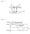
Fig. 2 shows a prior art example of the audio current in case of an over-current situation. Especially for self-oscillating systems, an over-current situation will result in a semi-permanent shutdown until the global control system has recovered. The resulting audio-current will be highly distorted and discontinues; -
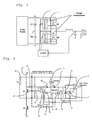
Fig. 3 shows the output stage of a single-ended Class D amplifier according to the invention, using a self-oscillating controlled current limiting scheme. The current detection is done locally by measuring the voltage drop across the switching device; -
Fig. 4 shows a preferred implementation according to the invention; -
Fig. 5 shows an example of the current waveform when the output stage is in the self-oscillating controlled current limiting mode. The resulting switching frequency is given by (T_ON+T_OFF)-1; and -
Fig 6 shows the audio current as a result of using the invention. The audio current is clipped, but no longer discontinued and by using the invention, the amplifier output stage is able to deliver "Music at all time". - According to the invention, the current limiting scheme and method provide a self-oscillating controlled current limiting mode.
- After detecting an over-current situation, the
driver 16 to theoutput switching stage 17 is forced to turn OFF the output stage. If the over-current is detected, the control circuitry according to the invention will force a predetermined OFF time. This OFF time could be implemented in thecomparator 6 used in the detection circuit. After the forced shutdown, the output stage is able to turn ON again according to thePWM signal 13 to the driver stage. If the over-current situation is still present, the current in theswitching device 17 will ramp up to thecurrent limit 22 and the output stage will be turned OFF again for the duration of the forced OFFtime 23. Thereby, the output stage will enter the self-oscillating controlled current limiting mode with a switching frequency given by (T_ON(24) + T_OFF(23))-1. - The self-oscillating controlled current limiting mode results in a self-oscillating current loop that cycle-by-cycle limits the current level and keeps the audio output intact but clipped. During this current-limit action, the amplifier control-loops will be saturated, which in the prior art stopped all switching action and caused unwanted audio artefacts.
- When the amplifier goes into the self-oscillating controlled current limiting mode, there is no communication with the global control loop. This is advantageous since any communication with the low- and high-side drivers is complicated. Even though there is no communication, it is still very easy to determine if the system is in current limiting mode. It is often required that current limiting is monitored and that the information can be displayed. By comparing the PWM-pulses in the power stage (Junction between Q1 and Q2 in
fig. 4 ) with the global control loop, one can determine in which state the amplifier is. If the global feedback control circuit (Fig. 3 ) is saturated and PWM-pulses in the power stage are detected, then the amplifier is in the self-oscillating controlled current limiting mode - The current detection method according to the invention eliminates the need for an external sense device. Instead, the voltage across the FET transistor is used as a measure of the current through it.
- In a Class D amplifier (as for any Switch Mode circuit), the FET transistors are either fully turned ON or fully turned OFF, and ON characteristics arc predominantly resistive. The invention takes advantage of this resistive nature of the FET transistors when turned ON and can by means of the invention sense the voltage across the MOSFET and thereby the current.
- It is not trivial to measure the voltage drop across a switching MOSFET. A direct measurement of the voltage drop across the device will require critical timing with regard to connection/disconnection of the probe circuitry in order to avoid destructive voltages when the switching device is in its off state. The invention presents a new-to-the-art way of sensing the voltage across the switching device by using a special network and a sense current (3+10) to give information about the voltage across the device and thereby the current flowing through it.
- According to the invention, the sense current is divided into two equal parts taking two different paths. The first path goes through a
diode 20 connected to theswitching device 17, and the second path goes through a similar diode 4 to acapacitor 8. Since the two diodes are essentially equal, the voltage across thecapacitor 8 will track the voltage across the switching device. During the OFF time of the switching device, the sense-current is bypassed by aswitch 11 to avoid wrongful charging of thesense capacitor 8. The sense voltage acrosscapacitor 8 is the input to acomparator 6. The input to the positive terminal of thecomparator 6 is a voltage-reference 7. This voltage reference 7 can be a fixed voltage or an adjustable voltage. By implementing an adjustable voltage reference, the current limit level can be changed by adjusting the voltage 7. Another way of controlling the current limit setting is by adding aresistor 21 in series with thediode D1 20. Instead of having the detection voltage drop solely across the switching device, part of the drop will now be across theresistor 21. This will effectively reduce the current limit setting. - In case that the detection voltage across
capacitor Cl 8 reaches the reference voltage 7, the output of the comparator will change state which indicates an oven-current situation. In case of an over-current situation, thecomparator output state 6 will force thedriver stage 16 to shut down the switching device. According to the invention, the comparator will have a built-in forced hold time, e.g. 1.25 microseconds, in case of an over-current situation. After the forced hold time, the switching device can be turned ON again. If the over-current situation is still present, the switching device is turned OFF again for the duration of the forced hold time. By doing this, the current protection scheme transform the output stage to a self-oscillating controlled current limiting loop.
Claims (11)
- A method for current sensing and current limiting in a self-oscillating class D amplifier comprising a Pulse Width Modulator, a driver circuit, one or more output switching semiconductors (17) and a global control system, the method including(i) current sensing directly across the terminals of said output switching semiconductors (17); and(ii) current limiting by means of a local autonomously controlled self-oscillating loop comprising a comparator circuit with inputs and outputs, reference level and detection level for said comparator controlling said driver circuit;where the method is characterized by an arrangement of current sources (3,10), diodes (4,20) and detection circuitry, creating one current path divided into two equal current paths, whereof the first current path detects the voltage across the switching device and consequently the voltage across the second current path reflects the hereby detected voltage and is equal to the voltage across the switching device.
- A method for current limiting according to claims 1, where the current limiting action is characterized by said driver circuit turning off said output switching semiconductors in case of an over-current detection.
- A method for current limiting according to claims 1 and 2, where the current limiting action is characterized by a fixed OFF time for said output switching semiconductors.
- A method for current limiting according to claims 1, 2 and 3, where the current limiting action is characterized by an asynchronously determined time for switching OFF for said output switching semiconductors.
- A method for current limiting according to claims 1, 2 and 3, characterized by said comparator changing output state according to reference level and detection level.
- A method for current limiting according to claim 1, characterized by said comparator having a forced hold time.
- A method for current sensing and limiting according to claims I to 6, characterized by the detecting and limiting acting having no communication with said global control system.
- A method for current sensing and limiting according to claims 1 to 7, characterized by integration into a chip (IC, Integrated Circuit).
- A self-oscillating class D amplifier comprising a Pulse Width Modulator, a driver circuit, one or more output switching semiconductors and a global control system where said self-oscillating class D amplifier comprises:(i) means for current sensing directly across the terminals of said output switching semiconductors;(ii) an arrangement of current sources, diodes and detection circuitry, creating one current path divided into two equal current paths, whereof the first current path detects the voltage across the switching device and consequently the voltage across the second current path reflects the hereby detected voltage and is equal to the voltage across the switching device;(iii) a local autonomously controlled self-oscillating loop comprising a comparator circuit with inputs and outputs, reference level and detection level for said comparator controlling said driver circuit;(iv) means for current limiting where said comparator circuit asynchronously controls said driver circuit at a fixed OFF time.
- A self-oscillating class D amplifier according to claim 9 comprising:a current detecting and limiting system having no communication with said global control system.
- A self-oscillating class D amplifier according to claim 10 comprising:a current detecting and limiting system integrated into a chip (IC, Integrated Circuit).
Applications Claiming Priority (2)
| Application Number | Priority Date | Filing Date | Title |
|---|---|---|---|
| DKPA200601680 | 2006-12-20 | ||
| PCT/IB2007/055247 WO2008075306A1 (en) | 2006-12-20 | 2007-12-20 | True current limiting (tcl) |
Publications (2)
| Publication Number | Publication Date |
|---|---|
| EP2092639A1 EP2092639A1 (en) | 2009-08-26 |
| EP2092639B1 true EP2092639B1 (en) | 2011-09-21 |
Family
ID=39323002
Family Applications (1)
| Application Number | Title | Priority Date | Filing Date |
|---|---|---|---|
| EP07859471A Not-in-force EP2092639B1 (en) | 2006-12-20 | 2007-12-20 | True current limit |
Country Status (6)
| Country | Link |
|---|---|
| US (1) | US7936216B2 (en) |
| EP (1) | EP2092639B1 (en) |
| CN (1) | CN101563842B (en) |
| AT (1) | ATE525804T1 (en) |
| ES (1) | ES2370867T3 (en) |
| WO (1) | WO2008075306A1 (en) |
Families Citing this family (3)
| Publication number | Priority date | Publication date | Assignee | Title |
|---|---|---|---|---|
| US10824986B2 (en) * | 2010-12-23 | 2020-11-03 | Bladelogic, Inc. | Auto-suggesting IT asset groups using clustering techniques |
| US9756185B1 (en) | 2014-11-10 | 2017-09-05 | Teton1, Llc | System for automated call analysis using context specific lexicon |
| DE102019210566B4 (en) * | 2019-07-17 | 2022-03-17 | Conti Temic Microelectronic Gmbh | Apparatus and method for measuring current flowing through a PWM-driven inductive load |
Family Cites Families (6)
| Publication number | Priority date | Publication date | Assignee | Title |
|---|---|---|---|---|
| US4415863A (en) | 1981-03-24 | 1983-11-15 | Pioneer Electronic Corporation | Pulse width modulation amplifier |
| US5973569A (en) * | 1998-02-25 | 1999-10-26 | National Semiconductor Corporation | Short-circuit protection and over-current modulation to maximize audio amplifier output power |
| US6108182A (en) * | 1998-10-30 | 2000-08-22 | Intersil Corporation | Overcurrent sensing circuit and self adjusting blanking |
| JP2002171140A (en) * | 2000-12-01 | 2002-06-14 | Mitsubishi Electric Corp | Audio signal amplification output circuit |
| US7595615B2 (en) * | 2005-04-05 | 2009-09-29 | Texas Instruments Incorporated | Systems and methods for providing over-current protection in a switching power supply |
| US7317355B2 (en) * | 2005-05-10 | 2008-01-08 | Texas Instruments Incorporated | Over-current detection for a power field-effect transistor (FET) |
-
2007
- 2007-12-20 US US12/519,472 patent/US7936216B2/en active Active
- 2007-12-20 AT AT07859471T patent/ATE525804T1/en not_active IP Right Cessation
- 2007-12-20 ES ES07859471T patent/ES2370867T3/en active Active
- 2007-12-20 WO PCT/IB2007/055247 patent/WO2008075306A1/en active Application Filing
- 2007-12-20 EP EP07859471A patent/EP2092639B1/en not_active Not-in-force
- 2007-12-20 CN CN200780047379XA patent/CN101563842B/en not_active Expired - Fee Related
Also Published As
| Publication number | Publication date |
|---|---|
| CN101563842B (en) | 2012-03-28 |
| ES2370867T3 (en) | 2011-12-23 |
| US7936216B2 (en) | 2011-05-03 |
| WO2008075306A1 (en) | 2008-06-26 |
| EP2092639A1 (en) | 2009-08-26 |
| US20100033247A1 (en) | 2010-02-11 |
| ATE525804T1 (en) | 2011-10-15 |
| CN101563842A (en) | 2009-10-21 |
Similar Documents
| Publication | Publication Date | Title |
|---|---|---|
| JP5135214B2 (en) | Inrush current control system and method with soft start circuit | |
| US7106031B2 (en) | Electric power supply apparatus having input switching circuit | |
| TWI448029B (en) | A system and method for protecting a power conversion system under open circuit and / or short circuit conditions | |
| US9772639B2 (en) | Dynamic current-limit circuit | |
| US20080043391A1 (en) | Timer reset circuit for overcurrent protection of switching power amplifier | |
| US7570118B1 (en) | Thermal overload protection circuit and method for protecting switching power amplifier circuits | |
| US7075373B2 (en) | Overcurrent protection circuit with fast current limiting control | |
| US7701287B2 (en) | Voltage detection type overcurrent protection device for class-D amplifier | |
| US7554399B1 (en) | Protection circuit and method for protecting switching power amplifier circuits during reset | |
| CN107834985B (en) | D-level amplifying circuit, control method thereof, audio output device and electronic equipment | |
| EP2387149B1 (en) | Over-current protection for a switch mode class D audio amplifier | |
| US8427804B2 (en) | Power amplifier | |
| Morrow et al. | A 20-W stereo class-D audio output power stage in 0.6-/spl mu/m BCDMOS technology | |
| US20120014025A1 (en) | Overcurrent protection circuit and semiconductor device | |
| US20090273874A1 (en) | Power switch circuit exhibiting over current and short circuit protection and method for limiting the output current thereof | |
| US20160233666A1 (en) | Current limiter circuit system | |
| JP2005249519A (en) | Current detection circuit, load driving circuit and storage device | |
| EP2092639B1 (en) | True current limit | |
| JPH03256407A (en) | Control circuit | |
| JP2008141612A (en) | Fault detection apparatus for load driving device, and load driving ic | |
| US6801058B1 (en) | Circuit and method for over-current sensing and control | |
| JP2000308253A (en) | Controller and method for power supply | |
| JP4517579B2 (en) | Current control circuit | |
| JP2004282959A (en) | Drive device of voltage-control type drive element | |
| US11217992B2 (en) | High-speed short-to-ground protection circuit for pass field-effect transistor (FET) |
Legal Events
| Date | Code | Title | Description |
|---|---|---|---|
| PUAI | Public reference made under article 153(3) epc to a published international application that has entered the european phase |
Free format text: ORIGINAL CODE: 0009012 |
|
| 17P | Request for examination filed |
Effective date: 20090720 |
|
| AK | Designated contracting states |
Kind code of ref document: A1 Designated state(s): AT BE BG CH CY CZ DE DK EE ES FI FR GB GR HU IE IS IT LI LT LU LV MC MT NL PL PT RO SE SI SK TR |
|
| DAX | Request for extension of the european patent (deleted) | ||
| 17Q | First examination report despatched |
Effective date: 20101123 |
|
| GRAP | Despatch of communication of intention to grant a patent |
Free format text: ORIGINAL CODE: EPIDOSNIGR1 |
|
| RTI1 | Title (correction) |
Free format text: TRUE CURRENT LIMIT |
|
| GRAS | Grant fee paid |
Free format text: ORIGINAL CODE: EPIDOSNIGR3 |
|
| GRAA | (expected) grant |
Free format text: ORIGINAL CODE: 0009210 |
|
| AK | Designated contracting states |
Kind code of ref document: B1 Designated state(s): AT BE BG CH CY CZ DE DK EE ES FI FR GB GR HU IE IS IT LI LT LU LV MC MT NL PL PT RO SE SI SK TR |
|
| REG | Reference to a national code |
Ref country code: GB Ref legal event code: FG4D |
|
| REG | Reference to a national code |
Ref country code: CH Ref legal event code: EP |
|
| REG | Reference to a national code |
Ref country code: IE Ref legal event code: FG4D |
|
| REG | Reference to a national code |
Ref country code: DE Ref legal event code: R096 Ref document number: 602007017431 Country of ref document: DE Effective date: 20111117 |
|
| REG | Reference to a national code |
Ref country code: ES Ref legal event code: FG2A Ref document number: 2370867 Country of ref document: ES Kind code of ref document: T3 Effective date: 20111223 |
|
| REG | Reference to a national code |
Ref country code: NL Ref legal event code: VDEP Effective date: 20110921 |
|
| PG25 | Lapsed in a contracting state [announced via postgrant information from national office to epo] |
Ref country code: FI Free format text: LAPSE BECAUSE OF FAILURE TO SUBMIT A TRANSLATION OF THE DESCRIPTION OR TO PAY THE FEE WITHIN THE PRESCRIBED TIME-LIMIT Effective date: 20110921 Ref country code: SE Free format text: LAPSE BECAUSE OF FAILURE TO SUBMIT A TRANSLATION OF THE DESCRIPTION OR TO PAY THE FEE WITHIN THE PRESCRIBED TIME-LIMIT Effective date: 20110921 Ref country code: LT Free format text: LAPSE BECAUSE OF FAILURE TO SUBMIT A TRANSLATION OF THE DESCRIPTION OR TO PAY THE FEE WITHIN THE PRESCRIBED TIME-LIMIT Effective date: 20110921 |
|
| LTIE | Lt: invalidation of european patent or patent extension |
Effective date: 20110921 |
|
| PG25 | Lapsed in a contracting state [announced via postgrant information from national office to epo] |
Ref country code: SI Free format text: LAPSE BECAUSE OF FAILURE TO SUBMIT A TRANSLATION OF THE DESCRIPTION OR TO PAY THE FEE WITHIN THE PRESCRIBED TIME-LIMIT Effective date: 20110921 Ref country code: CY Free format text: LAPSE BECAUSE OF FAILURE TO SUBMIT A TRANSLATION OF THE DESCRIPTION OR TO PAY THE FEE WITHIN THE PRESCRIBED TIME-LIMIT Effective date: 20110921 Ref country code: AT Free format text: LAPSE BECAUSE OF FAILURE TO SUBMIT A TRANSLATION OF THE DESCRIPTION OR TO PAY THE FEE WITHIN THE PRESCRIBED TIME-LIMIT Effective date: 20110921 Ref country code: LV Free format text: LAPSE BECAUSE OF FAILURE TO SUBMIT A TRANSLATION OF THE DESCRIPTION OR TO PAY THE FEE WITHIN THE PRESCRIBED TIME-LIMIT Effective date: 20110921 Ref country code: GR Free format text: LAPSE BECAUSE OF FAILURE TO SUBMIT A TRANSLATION OF THE DESCRIPTION OR TO PAY THE FEE WITHIN THE PRESCRIBED TIME-LIMIT Effective date: 20111222 |
|
| REG | Reference to a national code |
Ref country code: AT Ref legal event code: MK05 Ref document number: 525804 Country of ref document: AT Kind code of ref document: T Effective date: 20110921 |
|
| PG25 | Lapsed in a contracting state [announced via postgrant information from national office to epo] |
Ref country code: BE Free format text: LAPSE BECAUSE OF FAILURE TO SUBMIT A TRANSLATION OF THE DESCRIPTION OR TO PAY THE FEE WITHIN THE PRESCRIBED TIME-LIMIT Effective date: 20110921 |
|
| PG25 | Lapsed in a contracting state [announced via postgrant information from national office to epo] |
Ref country code: IS Free format text: LAPSE BECAUSE OF FAILURE TO SUBMIT A TRANSLATION OF THE DESCRIPTION OR TO PAY THE FEE WITHIN THE PRESCRIBED TIME-LIMIT Effective date: 20120121 Ref country code: CZ Free format text: LAPSE BECAUSE OF FAILURE TO SUBMIT A TRANSLATION OF THE DESCRIPTION OR TO PAY THE FEE WITHIN THE PRESCRIBED TIME-LIMIT Effective date: 20110921 Ref country code: SK Free format text: LAPSE BECAUSE OF FAILURE TO SUBMIT A TRANSLATION OF THE DESCRIPTION OR TO PAY THE FEE WITHIN THE PRESCRIBED TIME-LIMIT Effective date: 20110921 |
|
| PG25 | Lapsed in a contracting state [announced via postgrant information from national office to epo] |
Ref country code: EE Free format text: LAPSE BECAUSE OF FAILURE TO SUBMIT A TRANSLATION OF THE DESCRIPTION OR TO PAY THE FEE WITHIN THE PRESCRIBED TIME-LIMIT Effective date: 20110921 Ref country code: PT Free format text: LAPSE BECAUSE OF FAILURE TO SUBMIT A TRANSLATION OF THE DESCRIPTION OR TO PAY THE FEE WITHIN THE PRESCRIBED TIME-LIMIT Effective date: 20120123 Ref country code: PL Free format text: LAPSE BECAUSE OF FAILURE TO SUBMIT A TRANSLATION OF THE DESCRIPTION OR TO PAY THE FEE WITHIN THE PRESCRIBED TIME-LIMIT Effective date: 20110921 Ref country code: NL Free format text: LAPSE BECAUSE OF FAILURE TO SUBMIT A TRANSLATION OF THE DESCRIPTION OR TO PAY THE FEE WITHIN THE PRESCRIBED TIME-LIMIT Effective date: 20110921 Ref country code: RO Free format text: LAPSE BECAUSE OF FAILURE TO SUBMIT A TRANSLATION OF THE DESCRIPTION OR TO PAY THE FEE WITHIN THE PRESCRIBED TIME-LIMIT Effective date: 20110921 |
|
| PLBE | No opposition filed within time limit |
Free format text: ORIGINAL CODE: 0009261 |
|
| STAA | Information on the status of an ep patent application or granted ep patent |
Free format text: STATUS: NO OPPOSITION FILED WITHIN TIME LIMIT |
|
| PG25 | Lapsed in a contracting state [announced via postgrant information from national office to epo] |
Ref country code: MC Free format text: LAPSE BECAUSE OF NON-PAYMENT OF DUE FEES Effective date: 20111231 Ref country code: DK Free format text: LAPSE BECAUSE OF FAILURE TO SUBMIT A TRANSLATION OF THE DESCRIPTION OR TO PAY THE FEE WITHIN THE PRESCRIBED TIME-LIMIT Effective date: 20110921 |
|
| REG | Reference to a national code |
Ref country code: CH Ref legal event code: PL |
|
| 26N | No opposition filed |
Effective date: 20120622 |
|
| REG | Reference to a national code |
Ref country code: IE Ref legal event code: MM4A |
|
| REG | Reference to a national code |
Ref country code: DE Ref legal event code: R097 Ref document number: 602007017431 Country of ref document: DE Effective date: 20120622 |
|
| PG25 | Lapsed in a contracting state [announced via postgrant information from national office to epo] |
Ref country code: IE Free format text: LAPSE BECAUSE OF NON-PAYMENT OF DUE FEES Effective date: 20111220 Ref country code: CH Free format text: LAPSE BECAUSE OF NON-PAYMENT OF DUE FEES Effective date: 20111231 Ref country code: LI Free format text: LAPSE BECAUSE OF NON-PAYMENT OF DUE FEES Effective date: 20111231 |
|
| PG25 | Lapsed in a contracting state [announced via postgrant information from national office to epo] |
Ref country code: MT Free format text: LAPSE BECAUSE OF FAILURE TO SUBMIT A TRANSLATION OF THE DESCRIPTION OR TO PAY THE FEE WITHIN THE PRESCRIBED TIME-LIMIT Effective date: 20110921 |
|
| PG25 | Lapsed in a contracting state [announced via postgrant information from national office to epo] |
Ref country code: LU Free format text: LAPSE BECAUSE OF NON-PAYMENT OF DUE FEES Effective date: 20111220 |
|
| PG25 | Lapsed in a contracting state [announced via postgrant information from national office to epo] |
Ref country code: BG Free format text: LAPSE BECAUSE OF FAILURE TO SUBMIT A TRANSLATION OF THE DESCRIPTION OR TO PAY THE FEE WITHIN THE PRESCRIBED TIME-LIMIT Effective date: 20111221 |
|
| PG25 | Lapsed in a contracting state [announced via postgrant information from national office to epo] |
Ref country code: TR Free format text: LAPSE BECAUSE OF FAILURE TO SUBMIT A TRANSLATION OF THE DESCRIPTION OR TO PAY THE FEE WITHIN THE PRESCRIBED TIME-LIMIT Effective date: 20110921 |
|
| PG25 | Lapsed in a contracting state [announced via postgrant information from national office to epo] |
Ref country code: HU Free format text: LAPSE BECAUSE OF FAILURE TO SUBMIT A TRANSLATION OF THE DESCRIPTION OR TO PAY THE FEE WITHIN THE PRESCRIBED TIME-LIMIT Effective date: 20110921 |
|
| PGFP | Annual fee paid to national office [announced via postgrant information from national office to epo] |
Ref country code: ES Payment date: 20141215 Year of fee payment: 8 Ref country code: GB Payment date: 20141205 Year of fee payment: 8 |
|
| PGFP | Annual fee paid to national office [announced via postgrant information from national office to epo] |
Ref country code: IT Payment date: 20141216 Year of fee payment: 8 |
|
| PGFP | Annual fee paid to national office [announced via postgrant information from national office to epo] |
Ref country code: DE Payment date: 20141203 Year of fee payment: 8 |
|
| PGFP | Annual fee paid to national office [announced via postgrant information from national office to epo] |
Ref country code: FR Payment date: 20141212 Year of fee payment: 8 |
|
| REG | Reference to a national code |
Ref country code: DE Ref legal event code: R119 Ref document number: 602007017431 Country of ref document: DE |
|
| GBPC | Gb: european patent ceased through non-payment of renewal fee |
Effective date: 20151220 |
|
| REG | Reference to a national code |
Ref country code: FR Ref legal event code: ST Effective date: 20160831 |
|
| PG25 | Lapsed in a contracting state [announced via postgrant information from national office to epo] |
Ref country code: GB Free format text: LAPSE BECAUSE OF NON-PAYMENT OF DUE FEES Effective date: 20151220 Ref country code: DE Free format text: LAPSE BECAUSE OF NON-PAYMENT OF DUE FEES Effective date: 20160701 |
|
| PG25 | Lapsed in a contracting state [announced via postgrant information from national office to epo] |
Ref country code: FR Free format text: LAPSE BECAUSE OF NON-PAYMENT OF DUE FEES Effective date: 20151231 |
|
| PG25 | Lapsed in a contracting state [announced via postgrant information from national office to epo] |
Ref country code: IT Free format text: LAPSE BECAUSE OF NON-PAYMENT OF DUE FEES Effective date: 20151220 |
|
| PG25 | Lapsed in a contracting state [announced via postgrant information from national office to epo] |
Ref country code: ES Free format text: LAPSE BECAUSE OF NON-PAYMENT OF DUE FEES Effective date: 20151221 |
|
| REG | Reference to a national code |
Ref country code: ES Ref legal event code: FD2A Effective date: 20180710 |