EP2091676B1 - Method and apparatus for making two-piece beverage can components - Google Patents
Method and apparatus for making two-piece beverage can components Download PDFInfo
- Publication number
- EP2091676B1 EP2091676B1 EP07854860.9A EP07854860A EP2091676B1 EP 2091676 B1 EP2091676 B1 EP 2091676B1 EP 07854860 A EP07854860 A EP 07854860A EP 2091676 B1 EP2091676 B1 EP 2091676B1
- Authority
- EP
- European Patent Office
- Prior art keywords
- station
- disk
- processing stations
- shell
- providing
- Prior art date
- Legal status (The legal status is an assumption and is not a legal conclusion. Google has not performed a legal analysis and makes no representation as to the accuracy of the status listed.)
- Active
Links
Images


Classifications
-
- B—PERFORMING OPERATIONS; TRANSPORTING
- B21—MECHANICAL METAL-WORKING WITHOUT ESSENTIALLY REMOVING MATERIAL; PUNCHING METAL
- B21D—WORKING OR PROCESSING OF SHEET METAL OR METAL TUBES, RODS OR PROFILES WITHOUT ESSENTIALLY REMOVING MATERIAL; PUNCHING METAL
- B21D51/00—Making hollow objects
- B21D51/16—Making hollow objects characterised by the use of the objects
- B21D51/26—Making hollow objects characterised by the use of the objects cans or tins; Closing same in a permanent manner
- B21D51/2692—Manipulating, e.g. feeding and positioning devices; Control systems
-
- Y—GENERAL TAGGING OF NEW TECHNOLOGICAL DEVELOPMENTS; GENERAL TAGGING OF CROSS-SECTIONAL TECHNOLOGIES SPANNING OVER SEVERAL SECTIONS OF THE IPC; TECHNICAL SUBJECTS COVERED BY FORMER USPC CROSS-REFERENCE ART COLLECTIONS [XRACs] AND DIGESTS
- Y10—TECHNICAL SUBJECTS COVERED BY FORMER USPC
- Y10S—TECHNICAL SUBJECTS COVERED BY FORMER USPC CROSS-REFERENCE ART COLLECTIONS [XRACs] AND DIGESTS
- Y10S72/00—Metal deforming
- Y10S72/715—Method of making can bodies
Definitions
- the plurality of processing stations further comprises a lining station.
- the lining station is located between the shell press station and the conversion press station, and applies a sealant layer on a portion of the can end shell.
- a can end manufacturing apparatus 200 which carries out a method of the present invention is used to form a can end 202.
- a finished or substantially finished can end 202 includes a seaming curl joined to a center panel having a public side, product side, and a means for opening the center panel, typically either a thin film covering an aperture or a retainable tab overlying a frangible tear panel.
- Such a structure is the standard in two-piece beverage cans manufactures all over the world, and is described in countless publications.
- the first can end forming process station is a shell press 212.
- the shell press 212 is similar to the cupper in the can body manufacturing process.
- the shell press 212 deforms the disk 204 into a can end shell 216.
- the can end shell 216 is an end with no forming and no tab attached - just a flat disk with the outside diameter curled to accept a can neck.
- the forms the precise shape required for double seam formation (the operation that seals the can end to the flanged top of the can body after the can is filled).
- the can end shells 216 are continuously transferred to a first rollover station 220 where the shell orientation is reversed.
- the public side of each can end shell 216 is flipped to face downwardly.
Landscapes
- Engineering & Computer Science (AREA)
- Automation & Control Theory (AREA)
- Mechanical Engineering (AREA)
- Details Of Rigid Or Semi-Rigid Containers (AREA)
- Specific Conveyance Elements (AREA)
Description
- The invention relates to a method and apparatus for making two-piece beverage can components. More particularly, the present invention relates to a method and apparatus for continuously making two-piece beverage can components from a plurality of pre-punched metallic disks.
- Two-piece cans are widely used in the beverage industry to package soft drinks, alcoholic drinks, and the like. These two-piece beverage cans typically include a thin-walled tubular body portion having a closed end and an open end. The open end is sealed by a can end once the can body has been filled with a liquid beverage.
- Can bodies are produced from a metal sheet product, typically aluminum or steel. The aluminum or steel sheet arrives at the can manufacturing plant in very large coils. The sheet is fed continuously from an uncoiler or payoff reel into a cupping press which cuts out thousands of disks per minute and forms them into shallow cups. This is called the blank and draw process. Surplus material from the coil is recycled, and sold back to the material supplier.
- The shallow cups are transported to a bodymaker where the can body begins to take its final shape. In the bodymaker, the shallow cup goes through a process called draw and iron or DI. During DI, the shallow cup is placed in front of a moving ram which forces it through a series of precision rings, each a little smaller than the previous one. This reduces the thickness of the metal (wall ironing) and, as a result, the can gets taller. At the end of the stroke the base is formed, and the can body is removed from the ram.
- A trimmer shears material excess about the open end of the can body. This trimming process insures that the can body is the correct height, and that the rim about the open end is uniform and free of earring (misshapen metal). Again, the surplus material from this process is recycled.
- The trimmed can bodies then pass through highly efficient washers to remove lubricants used during the forming process and to prepare the can body outer surface for coating and printing. Cans are then dried in a drier or oven.
- Depending on customer and design requirements, the outer surface of the can bodies may be externally coated with a white or clear base coat at a base coater station.
- The next step is a highly sophisticated decorator, which applies a design to the outer surface of the can body using up to six colors. All six colors are printed onto the can body in the same operation. A clear-coat over-varnish is sometimes added to the printed can bodies to give a glossy finish.
- Next, the inner surface of each can body is sprayed with a coating. This special layer is to protect the product in the can from interaction with the metal of the can body.
- The decorated can bodies are then passed through a necker/flanger which reduces the diameter of the open end of the can body. This gives the can bodies the characteristic neck shape. Here, the diameter of the top of the can is reduced or 'necked-in'. The top of the can is flanged outwards to enable the can end to be seamed to the can body after the can bodies are filled with a liquid beverage.
- The can bodies are quality tested at each stage of manufacture. At the final stage, the can body is put through a series of additional tests, including a light test and internal and external inspection cameras. Any defective can bodies are automatically rejected.
- Finally, the cans are packed on to pallets which are then either sent to a warehouse for storage or transported directly to the beverage producer for filling.
- The can ends or lids are produced in a separate process. Can end manufacture begins with a large coil of aluminum or steel. The metal sheet is fed through a shell press, which stamps out and forms the basic can end shell. The can end shell is an unfinished can end with no forming and no tab attached - just a flat disk with the outside diameter curled to accept a can body neck. Scrap metal from the coil is collected and recycled.
- The shells are transferred to a balancer or manual rollover station where the orientation of the shell is reversed so that a public side is face down and the product side is face up.
- A special type of sealant called compound is applied to the inside curl of the shell. This ensures a perfect curl when the finished can end is seamed on to can body. This process is called lining and is done at very high speed on a compound lining machine.
- Again, the shells are transferred to a balancer or manual rollover station where the orientation of the shell is reversed. In this beverage can component process the product side is turned face down, and the public side is turned face up.
- The final step in the can end process is converting the lined shell into a finished end. This is done in a conversion press. This process forms and scores the shell into a finished or substantially finished can end or lid, and attaches a tab to the can end. There can be eight or more separate stages, or progressions, involved in converting a shell into a finished end at the conversion press.
- Typically, the conversion press also produces a strip of tabs from a narrow coil of aluminum or steel sheet which is fed into an integral tab die. There are typically thirteen to seventeen working stages involved in producing the can end tab.
- At all stages of the can end production process, the ends are constantly scanned by cameras and sophisticated leak detection systems. Functional checks are performed by computer controlled equipment and are backed up by extensive visual checks. These tests are essential in confirming the integrity of the product before the ends are packed into paper sleeves and palletized for shipment.
- The processes for producing the components of a two-piece beverage can, the can bodies, can ends, and can end tabs, all begin with a large coil of aluminum or steel sheet being fed from an uncoiler or payoff reel to a first two-piece beverage can component process. These coils may weigh between 8 to 15 tons or even more, and the receiving and handling costs associated with processing the coils is considerable. Because the coils are of a fixed, uniform width, scrap accumulation is significant, and can exceed 10% of the weight of the coil.
- In addition, this scrap must be processed to transfer it from the plant. The scrap may be baled or compacted for transport. These processes are costly to run and maintain.
- Moreover, the use of coils can slow down two-piece beverage can component manufacture as a new coil must be loaded onto the uncoiler or payoff reel when the old coil is spent.
- Thus, there is a need for a method of forming two-piece beverage can components which reduces scrap accumulation and improves productivity.
- The present invention is provided to solve the problems discussed above and other problems, and to provide advantages and aspects not provided by prior methods of this type. A full discussion of the features and advantages of the present invention is deferred to the following detailed description, which proceeds with reference to the accompanying drawings.
- The present invention is directed to a method of forming two-piece beverage can components. The method comprises the steps of providing a plurality of pre-punched metallic disks in a uniform orientation to promote and facilitate automation as a first step in a process for manufacturing two-piece beverage can components providing a disk feeder to transfer at least one of the plurality of pre-punched metallic disks; providing a plurality of processing stations in operative alignment with the disk feeder, transferring a first disk from the plurality of pre-punched metallic disks via the disk feeder to a first station in the plurality of processing stations; performing a two-piece beverage can component manufacturing process on the first disk at the first station to form a deformed disk; removing the deformed disk from the first station; and transferring the deformed disk to each subsequent processing station in the plurality of processing stations, and performing a further two-piece beverage can component manufacturing process in each subsequent processing station to produce a substantially finished two-piece beverage can component.
- In one embodiment, the two-piece beverage can component is a finished or substantially finished can body. The plurality of processing stations comprises a cupper station, a bodymaker station, a trimmer station, and a necking station. The cupper station receives the first disk from the disk feeder, and deforms the first disk to form a shallow cup. The bodymaker station includes tooling for drawing and thinning the shallow cup to form a thin-walled tubular can body having an open end and an opposing closed end The trimmer station includes a knife for shearing excess material about the open end of the tubular can body. The necking station includes tooling for reducing the diameter of the open end of the tubular can body.
- In one aspect of the embodiment, the plurality of processing stations further comprises a washer station, a decorative coating station, a decorative coating dryer station, an inner surface coating station, and a second dryer station. The washer station is located between the trimmer station and the necking station, and is provided to clean the inner and outer surfaces of the thin-walled tubular can body. The decorative coating station is located between the washer station and the necking station. The decorative coating station applies a decorative layer of coating to the outer surface of the thin-walled tubular can body. The decorative coating dryer station is located between the decorative coating station and the necking station. The inner surface coater is located between the decorative drying station and the necking station. The inner surface coater applies an inner surface layer of coating to the inner surface of the thin-walled tubular can body. The second drying station is located between the inner surface coater and the necking station.
- In another aspect of the embodiment, the plurality of processing stations further comprises a base coater station and a base coat dryer station. The base coater station is located between the washer station and the decorative coating station, and applies a base layer of coating to the outer surface of ther thin-walled tubular can body. The base coat dryer station is located between the base coater station and the decorative coating station.
- In another aspect of the embodiment, the washer station includes a drying step.
- In another aspect of the embodiment, the plurality of processing stations further comprises a plurality of bodymaker stations.
- In another aspect of the embodiment, the plurality of processing stations further comprises a lubricator station located between the disk feeder and the cupper station.
- In another aspect of the embodiment, the two-piece beverage can component is a finished or substantially finished can end or lid. The plurality of processing stations comprises a shell press station and a conversion press station. The shell press receives the first disk from the disk feeder, and deforms the first disk to form a can end shell. The conversion press receives the can end shell, and further deforms the can end shell to form a finished or substantially finished can end.
- In another aspect of the embodiment, the plurality of processing stations further comprises a lining station. The lining station is located between the shell press station and the conversion press station, and applies a sealant layer on a portion of the can end shell.
- In another aspect of the embodiment, the plurality of processing stations further comprises a first rollover station and a second rollover station. The first rollover station located between the shell press station and the lining station. The first rollover station reverses an orientation of the can end shell received from the shell press station. The second rollover station is located between the lining station and the conversion press station. The second rollover station reverses an orientation of the can end shell received from the lining station.
- In another aspect of the embodiment, the plurality of processing station further comprises a can end tab station. The can end tab station includes a source of metal sheet, and forms the metal sheet into a can end tab.
- In another aspect of the embodiment, the can end tab is staked to the can end shell during a process carried out at the conversion press station.
- In another embodiment, the two-piece beverage can component is a can end tab. The plurality of processing stations comprises a can end tab station and a conversion press station. The can end tab receives the first disk from the disk feeder, and deforms the first disk to form a can end tab. The conversion press station receives the can end tab, and stakes the can end tab to a can end shell.
- Also disclosed is a method of forming a can body comprising the steps of providing a disk, forming the disk into a cup, reforming the cup in a draw and iron process. The disk is of a metallic substrate coated with an epoxy-based organic coating. The cup is reformed to form a can body having a circumferential side wall and an integral bottom wall opposite an open end. A level of the epoxy-based organic coating is maintained on the metallic substrate throughout the forming and reforming steps. The level of the epoxy-based organic coating left on the metallic substrate may be sufficient to protect an interior surface of the can body from contact with a beverage deposited therein.
- Also disclosed is a method of forming a can body comprising the steps of providing a cup and drawing and ironing the cup. The cup is of a metallic substrate having an epoxy-based organic coating deposited thereon. The has a circumferential side wall integral with a closed bottom portion and an open end opposite the closed bottom portion. During the drawing and ironing step, the side wall of the cup is elongated while a level of the epoxy-based organic coating is maintained on the metallic substrate. The level of the epoxy-based organic coating maintained on the metallic substrate may be sufficient to withstand contact by a beverage deposited within the drawn and ironed cup.
- Also disclosed is a method of forming a can body comprising the steps of providing a disk, forming the disk into a cup, reforming the cup, and reducing a diameter of an open end of the reformed cup. The disk is of a metallic substrate coated with an epoxy-based organic coating. The cup has a circumferential side wall integral with a closed bottom. The cup is reformed in a draw and iron process to thin and elongate the side wall. The diameter of the open end is reduced at a necking station. At least a portion of the epoxy-based organic coating is maintained on the substrate throughout the forming, reforming and reducing steps. The portion of the epoxy-based organic coating may form a layer over an interior surface of the cup after the forming, reforming and reducing steps. The layer may be sufficient to coat the entire interior surface of the cup below the reduced diameter of the opening.
- Also disclosed is a method of forming a can body comprising the steps of forming a cup, coating the cup, and reforming the cup. The cup is formed from a segment of a metallic substrate. The cup has a circumferential side wall integral with a closed bottom portion and an open end opposite the closed bottom portion. The cup is coated with an epoxy-based organic coating. The cup is reformed in a draw and iron process to elongate the side wall while maintaining at least a portion of the epoxy-based organic coating on the reformed cup. The portion of the epoxy-based organic coating may be sufficient to eliminate further coating with the epoxy-based organic coating in a further process. The portion of the epoxy-based organic coating may be sufficient to protect an interior surface of the reformed cup from contact with a beverage deposited therein.
- Other features and advantages of the invention will be apparent from the following specification taken in conjunction with the following drawings.
- To understand the present invention, it will now be described by way of example, with reference to the accompanying drawings in which:
-
FIG. 1 is a schematic of a prior art can body manufacturing process; -
FIG. 2 is a schematic of a prior art can end manufacturing process; -
FIG. 3 is a schematic of a can body manufacturing process of the present invention; -
FIG. 4 is a flowchart of a can body manufacturing process of the present invention; -
FIG. 5 is a schematic of a can end manufacturing process of the present invention; -
FIG. 6 is a flowchart of a can end manufacturing process of the present invention; -
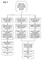
FIG. 7 is a flowchart of a method of manufacturing can bodies, can ends, and can end tabs; -
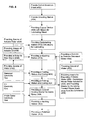
FIG. 8 is a flowchart of an existing method of manufacturing a beverage container component; and -
FIG. 9 is a flowchart of a method of manufacturing a beverage container component including providing pre-lubricated disks and showing eliminated steps from the existing method illustrated inFIG. 8 . - While this invention is susceptible of embodiments in many different forms, there is shown in the drawings and will herein be described in detail preferred embodiments of the invention with the understanding that the present disclosure is to be considered as an exemplification of the principles of the invention and is not intended to limit the broad aspect of the invention to the embodiments illustrated.
-
FIGS. 1 and2 illustrate typical two-piece beverage can component manufacturing processes 10, 20, 30. The processes include acoil delivery station component processing stations recycle process stations FIG. 1 , the flat metal sheet is converted into a finished or substantially finished two-piece beverage can component, e.g. a can body, a can end (lid), or a can end tab. In the manufacturing process ofFIG. 2 , the flat metal sheet is converted in to a finished or substantially finished can end. - Now preferring to
FIGS. 3-7 , the two-piece beverage can component manufacturing method of the present invention does not include a coil delivery station. Rather, the method of the present invention replaces the metal coil delivery station with a disk feeder for transferring at least one of a plurality of pre-punclaed metallic disks to a plurality of two-piece beverage can component processing stations. Accordingly, the present invention is generally directed to a method for forming two-piece beverage can components comprising the steps of providing a plurality of pre-punched metallic disks; providing a disk feeder for transferring at least one of the plurality of pre-punched metallic disks; providing a plurality of processing stations in operative alignment with the disk feeder, transferring a first disk from the plurality of pre-punched metallic disks via the disk feeder to a first station in the plurality of processing stations; performing a two-piece beverage can component manufacturing process on the first disk at the first station to form a deformed disk; removing the deformed disk from the first station; and transferring the deformed disk to each subsequent processing station in the plurality of processing stations, and performing a further two-piece beverage can component manufacturing process in each subsequent processing station to produce a substantially finished two-piece beverage can component. - Referring to
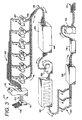
FIGS. 3-4 , in one embodiment, a canbody manufacturing apparatus 100 which carries out a method of the present invention is used to form acan body 102. A finished or substantially finished canbody 102 includes a thin-walled, tubular sidewall having a closed end and an opposing open end. The sidewall carries indicia typically identifying the contents, brand, size etc. of the finished two-piece beverage can. The closed end is domed inwardly. The opposing end is necked radially inwardly to reduce the diameter of the open end. Such a structure is the standard in two-piece beverage cans manufactures all over the world, and is described in countless publications. - The method of this embodiment includes providing a plurality of a plurality of pre-punched
metallic disks 104. Thedisks 104 are preferably punched at location other than the can body manufacturing site, and shipped to and received by the can body manufacturing plant. Accordingly, large numbers ofpre-punched disks 104 can be received at the can body manufacturing site in any one of number of modes. Preferably, thedisks 104 are arranged in a uniform orientation that promotes automation. For instance, thedisks 104 can be delivered such that eachdisk 104 is directionally consistent, e.g. in rolling direction and/or grain direction, with the adjacent the disks. Thedisks 104 can be received in sleeves and in proper orientation so that transfer and loading is facilitated. - The delivered pre-punched disks may be further preformed at a location other than the can body manufacturing plant. It may be desirable for the pre-punched disks to be formed into a shallow cup, having bottom portion joined to a circumferential sidewall. The sidewall is preferably very short and may be tapered outwardly from the outer perimeter of the bottom portion wherein the opening of the shallow cup-shaped disk is slightly wider than the outer perimeter of the bottom portion. This variation would facilitate stacking, orientation, and further processing of the pre-punched disks at the can body manufacturing plant. As used herein the term "pre-punched disk," and/or simply "disk," unless otherwise modified, is intended to mean a disk which is can be either flat or of the shallow cup-shape as described above.
- The method further includes providing a
disk feeder 108 for transferring at least one of the plurality of pre-punched metallic disks. Thedisk feeder 108 is an automated delivery system which could rely on gravity, spring-force, vacuum, etc. to remove adisk 104 from the plurality of disks and transfer thedisk 104 to a first can body forming process station. - The disks may be pre-lubricated or a
lubricator station 112 may be located between thedisk feeder 108 and the next process station in the manufacturing sequence. Thelubricator 112 applies a thin coating of oil to facilitate metal forming during the forming of the can body. - A cupper station 116 is in operative alignment with the
disk feeder 108, and receives lubricateddisks 104 for processing. The cupper station 116 deforms thedisk 104 in a drawing process to form ashallow cup 120. The cupper station may simultaneously receive and processmultiple disks 108 for increased productivity. Once complete, theshallow cups 120 drop from the cupper station 116 onto a cup conveyor for transfer to the next station. - The
shallow cups 120 may be pre-lubricated or another lubricator station 122 may be located between the cupper station 116 and the next process station in the manufacturing sequence. The lubricator 122 applies a thin coating of oil to facilitate metal forming during the forming of the can body. - The
shallow cups 120 are transferred continuously to one ormore bodymaker stations 124. Eachbodymaker station 124 includes tooling for drawing and thinning theshallow cups 120 to form thin-walled tubular canbodies 128 having an open end and an opposing closed end. Eachbodymaker station 124 contains a tool called a punch, which forms the shape of thecan body 128 by forcing thecup 120 through a series of progressively smaller circular ironing rings. This action draws the metal up the sides of the punch, ironing it into acan body 128. As thecup 120 is forced through the rings, its diameter is reduced, its walls are thinned and its height is increased. At the end of the punch stroke, the bottom is formed into a dome shape that strengthens the bottom of thecan body 128. During this process, referred to as wall ironing, the metal must be lubricated to reduce frictional heat. - The thin-walled, tubular can
bodies 128 are transferred from thebodymakers 124 totrimmer stations 132. The trimmer station includes a knife for shearing excess material about the open ends of the tubular canbodies 128. This process adapts the canbodies 128 to a uniform, predetermined height. - The can
bodies 128 are then continuously transferred to a washer station 136. The washer 136 removes the forming lubricants before the application of outside decoration (or label) and inside protective coating. The washed canbodies 140 are discharged through adryer station 144 where the canbodies 128 are dried with forced hot air. - Depending on end user requirements, a base layer of coating can be applied to the outer surface of the
can bodies 128 at abase coater station 148. The base coating layer is generally a white or clear base coat. A basecoat dryer station 152 may be provided for curing the base coat layer. - The can
bodies 128 are then continuously transferred to adecorative coating station 156. Thedecorative coating station 156 applies a decorative layer of coating (ink) to the outer surface of the thin-walled tubular canbodies 128. The inked canbodies 128 move to a rotating varnish application roll that applies a clear coating over the entire outer sidewall. The clear coating protects the ink from scratching and contains lubricants that facilitate can conveying. - The can
bodies 128 are transferred from thedecorator 156 onto a pin (so that only the inside surface is contacted) and is conveyed through a decorator coating, or "pin," oven/drier station 160 where the ink is dried with forced hot air. - Following application and curing of the exterior decorative layer, the can
bodies 128 are conveyed to an innersurface coater station 164. Thisstation 164 includes a bank of spray machines that spray the inner surfaces of thecan bodies 128 with an epoxy-based organic protective coating. The inside coating is also cured by forced hot air at anotherdryer station 168. The coating prevents the beverage from contacting or reacting with the metal of the inner surface of thecan body 128. - After the can
bodies 128 leave thedrier station 168, they pass through a lubricator station that applies a thin film of lubricant to the exterior of the top (open end) where a neck and a flange will be formed. A necker/flanger station 176 reduces the diameter of the open ends of thecan bodies 128, and gives the cans the characteristic neck shape. Here the diameter of the top of the can is reduced or "necked-in." The top of the can is flanged outwards to enable the end to be seamed on after the cans are filled with a beverage. Following this step, a finished or substantially finished, as in suitable for use by a beverage manufacturer, canbody 102 is produced. - All finished cans are evaluated for leakage at a
light tester station 182. The can flange is clamped against a sealing surface and, as the machine rotates, the outside surface is exposed to a bank of extremely bright lights. A photocell inside the can detects any entering light, triggering a reject mechanism. Rejected cans are recycled. After testing, the finished cans are placed on pallets for shipment to the customer filling operations. - Now referring to
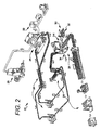
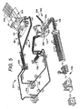
FIGS 5-6 , a second embodiment of the present invention is illustrated. Here, a can endmanufacturing apparatus 200 which carries out a method of the present invention is used to form a can end 202. A finished or substantially finished can end 202 includes a seaming curl joined to a center panel having a public side, product side, and a means for opening the center panel, typically either a thin film covering an aperture or a retainable tab overlying a frangible tear panel. Such a structure is the standard in two-piece beverage cans manufactures all over the world, and is described in countless publications. - The method of this embodiment includes providing a plurality of a plurality of pre-punched
metallic disks 204. Thedisks 204 are preferably punched at location other than the can end manufacturing site, and shipped to and received by the can end manufacturing plant. Accordingly, large numbers ofpre-punched disks 204 can be received at the can end manufacturing site in any one of number of modes. Preferably, thedisks 204 are arranged in a uniform orientation that promotes automation. For instance, thedisks 204 can be delivered such that eachdisk 204 is directionally consistent, e.g. in rolling direction and/or grain direction, with the adjacent the disks. Thedisks 204 can be received in sleeves and in proper orientation so that transfer and loading is facilitated. Can enddisks 204 are preferably pre-coated on both the public and product sides with organic protective coatings containing lubricants. There are no plate lubrication, washing, coating or baking operations in the modem end manufacturing plant. - The method further includes providing a
disk feeder 208 for transferring at least one of the plurality of pre-punched metallic disks. Thedisk feeder 208 is an automated delivery system which could rely on gravity, spring-force, vacuum, etc. to remove adisk 204 from the plurality of disks and transfer thedisk 204 to a first can end forming process station. - The
disks 204 may be pre-lubricated or another lubricator station may be located between thefeeder 208 and the next process station in the manufacturing sequence. The lubricator applies a thin coating of oil to facilitate metal forming during the forming of the can end shell. - The first can end forming process station is a
shell press 212. Theshell press 212 is similar to the cupper in the can body manufacturing process. Theshell press 212 deforms thedisk 204 into a can endshell 216. The can end shell 216 is an end with no forming and no tab attached - just a flat disk with the outside diameter curled to accept a can neck. The forms the precise shape required for double seam formation (the operation that seals the can end to the flanged top of the can body after the can is filled). - The can end
shells 216 are continuously transferred to afirst rollover station 220 where the shell orientation is reversed. Here, the public side of each can end shell 216 is flipped to face downwardly. - The can end
shells 216 are transferred to alining station 224. At the lining station 224 a special type of sealant called compound is applied to the inside curl of eachshell 216. This ensures a perfect curl when the finished end is seamed on to the can body. Inspection cameras may be located after thelining station 224 to inspect theshells 216. - The can end
shells 216 are then continuously transferred to asecond rollover station 228 where the shell orientation is reversed. Here, the product side of each can end shell 216 is flipped to face downwardly. - Prior to the final step, the can end
shells 216 may be pre-lubricated or another lubricator station may be located between thelining station 224 and the next process station in the manufacturing sequence. The lubricator applies a thin coating of oil to facilitate metal forming during the forming of the converted can end. - The final part of the process is converting the lined
shells 216 into finished or substantially finished can ends 232. This is done at aconversion press station 236. Here, the can endshells 216 are further deformed; the public side of the center panels are scored (or the apertures are formed); and a can end tab is staked to the public side of the center panel (or a peelable thin film cover is attached to the center panel to cover the aperture). - In the case where a tab is staked to the center panel of the can end, the method includes a can end
tab station 300. The can endtab station 300 is located adjacent or is part of theconversion press 236. The can endtab station 300 requires a source of metal sheet, preferably a plurality of can end tab disks 244 with a can end tab disk feeder 248 to transfer thedisks 304 to the can endtab station 300. Again, thedisks 304 are preferably punched at location other than the can end tab manufacturing site, and shipped to and received by the can end tab manufacturing plant. Accordingly, large numbers ofpre-punched disks 304 can be received at the can end tab manufacturing site in any one of number of modes. The can endtab station 300 deforms thedisks 304 to form tabs which are staked to the public side of the center panel of the can end at theconversion press station 236. - The finished or substantially finished can ends 232 are packaged at a
packaging station 240 for shipment to an end user. - Referring to
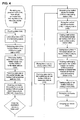
FIG. 7 , a flowchart for manufacturing two-piece beverage can components is illustrated. In this embodiment, the can bodies, can ends, and the can end tabs can be produced in one manufacturing location. Here, three different sizes of disks are delivered to the manufacturing site and converted can bodies, can ends, and can end tabs. - An existing method of manufacturing components for a two-piece beverage can is illustrated in
FIG. 8 . The method ofFIG. 8 comprises the steps of providing a coil of aluminum sheet 400, providing an uncoilingstation 404, providing a cupper station 408, providing abodymaking station 412, providing awashing station 416, providing acoating station 420, providing aprinting station 424, providing ansecond coating station 428 for coating the interior wall of the can body, providing a neckingstation 432, providing apalletizer station 433. - As illustrated in
FIG. 8 , the cupper station 408 includes means for providing a lubrication to the aluminum sheet which is punched into disks and formed into shallow cups at this station 408. Thebodymaking station 412 also includes means for providing lubrication during the body forming process which further includes a source ofwater 434 and a source ofsoluble oil 435. - The
washing station 416 includes a source of hot water 436 which includes a source ofwater 440 and aboiler 444 to warm the water. Thewashing station 416 further comprises a source of deionized water 448 which includes a source ofwater 452 and adeionizer 456. Thewashing station 416 still further comprises a means for disposing ofwaste water 460, a wastewater treatment substation 464, and a means for delivering treated waste water away from thestation 468. - A new method is illustrated in
FIG. 9 . As briefly noted above, a method of manufacturing two-piece beverage can components where pre-lubricated and/or pre-coated disks are provided is contemplated. Most preferably, the method includes providing aluminum disks which have been precoated with an epoxy-based organic protective coating, such as the coating provided at thecoating station 164 described in the previous embodiment. One object is to provide a pre-coated metallic substrate wherein at least a portion of the coating would be maintained throughout the can body forming process and wherein the portion of the coating maintained would be sufficient to protect an interior surface of the can body from a beverage deposited therein. The integrity of the coating is maintained wherein an interior surface of the can body would be protected from contact with a beverage deposited and sealed therein. - Thus, another object of this method is to eliminate many of the steps associated with the method of
FIG. 8 . This method accomplishes the elimination of steps by providing a pre-coated disk of a metallic substrate. The pre-coated disks contemplated by this method allow the following steps to be eliminated: the cupper station 408 need not include means for providing lubrication; thebodymaker 412 does not require a source of lubricant; thewashing station 416 is not required; thecoating station 420 is not required; and thesecond coating station 428 for coating an interior wall of the can body is not required. - Accordingly, the method illustrated in
FIG. 9 comprises the steps of: providing a plurality of pre-punched, pre-coated disks 500; feeding each of the plurality of pre-coated disks into a bodymaker at abody forming station 504; forming the pre-coated disks into a drawn and ironed canbody 508; printing the can body with information at aprinting station 512; curing the printing in anoven 516; necking the open end of the can body atnecker station 520; and finally palletizing the can bodies at apalletizer station 524. - The method shown in
FIG. 9 contemplates receiving pre-coated aluminum disks from an outside vendor; however, it would not depart from the spirit of the invention to precoat the disks at the can body manufacturing location with or on specifically designed machines. Thus, it would be possible to receive pre-coated disks for a first ironing operation (a low percentage of drawing), recoat the pre-formed cups, and finish the drawing operation. Likewise, it would not depart from the spirit of the invention to receive and/or reform cups produced from a metallic substrate, e.g. a disk of aluminum, and coat the cup with an epoxy-based organic coating subsequent to forming. The cup is then reformed in a draw and iron process without having to recoat the reformed cup in a subsequent coating operation. - Trials have been conducted using the method of
FIG. 9 . The aim of the trial was to evaluate coating performance. Several shallow cups were coated in advance with an epoxy-based organic protective coating, specifically a thermoplastic powder, thermosetting epoxy powder, polyurethane white basecoat and an organosol basecoat. With the bodymaker functioning at typical manufacturing speeds, can bodies were produced having with coating on inside and outside surfaces. - One of ordinary skill in the art would appreciate that the terms "first," "second," "upper," "lower," etc. are used for illustrative purposes only and are not intended to limit the embodiments in any way. The term "plurality" as used herein is intended to indicate any number greater than one, either disjunctively or conjunctively as necessary, up to an infinite number. The terms "joined" and/or "connected" as used herein are intended to put or bring two elements together so as to form a unit, and any number of elements, devices, fasteners, etc. may be provided between the joined or connected elements unless otherwise specified by the use of the term "directly" and/or supported by the drawings.
- While the specific embodiments have been illustrated and described, numerous modifications come to mind without significantly departing from the spirit of the invention, and the scope of protection is only limited by the scope of the accompanying Claims.
Claims (15)
- A method of forming two-piece beverage can components (102, 202), the method comprising the steps of:providing a plurality of pre-punched metallic disks (104, 204, 304) in a uniform orientation to promote and facilitate automation as a first step in a process for manufacturing two-piece beverage can components;providing a disk feeder (108, 208, 248) to transfer at least one of said plurality of pre-punched metallic disks (104, 204, 304);providing a plurality of processing stations (112, 116, 122, 124, 132, 136, 144, 148, 162, 156, 160, 164, 168, 176, 182, 212, 220, 224, 228, 236, 240, 300) in operative alignment with said disk feeder (108, 208, 248);transferring a first disk from said plurality of pre-punched metallic disks (104, 204, 304) via said disk feeder (108, 208, 248) to a first station (116, 212) in the plurality of processing stations;performing a two-piece beverage can component manufacturing process on said first disk at said first station (116, 212) to form a deformed disk (120, 216):removing said deformed disk (120, 216) from said first station (116, 212); andtransferring said deformed disk (120, 216) to each subsequent processing station (122, 124, 132, 136, 144, 148, 152, 156, 160, 164, 168, 176, 182, 220, 224, 228, 236, 240, 300) in said plurality of processing stations, and performing a further two-piece beverage can component manufacturing process in each subsequent processing station to produce a substantially finished two-piece beverage can component (102, 232).
- The method of claim 1 wherein said plurality of processing stations comprises:a cupper station (116), said cupper station receiving said first disk from said disk feeder (108), and deforming said first disk to form a shallow cup (120);a bodymaker station (124), said bodymaker station including tooling for drawing and thinning said shallow cup to form a thin-walled tubular can body (128) having an open end and an opposing closed end;a trimmer station (132), said trimmer station including a knife for shearing excess material about said open end of said tubular can body (128); anda necking station (176), said necking station including tooling for reducing the diameter of said open end of said tubular can body (128).
- The method of claim 2 wherein said plurality of processing stations further comprises:a washer station (136) located between said trimmer station (132) and said necking station (176), said washer station cleaning inner and outer surfaces of said thin-walled tubular can body (128);a decorative coating station (156) located between said washer station (136) and said necking station (176), said decorative coating station applying a decorative layer of coating to said outer surface of said thin-walled tubular can body (128);a decorative coating dryer station (160) located between said decorative coating station (156) and necking station (176);an inner surface coater station (164) located between said decorative drying station (160) and said necking station (176), said inner surface coater station applying a inner surface layer of coating to said inner surface of said thin-walled tubular can body (128); anda second drying station (168) located between said inner surface coater (164) and said necking station (176).
- The method of claim 3 wherein said plurality of processing stations further comprises:a base coater station (148) located between said washer station (136) and said decorative coating station (156), said a base layer of coating applied to said outer surface of said thin-walled tubular can body (128) at said base coater station: anda base coat dryer station (152) located between said base coater station (148) and said decorative coating station (156).
- The method of claim 3 wherein said washer station (136) includes a drying step (144).
- The method of claim 2 wherein said plurality of processing stations further comprises:a plurality of bodymaker stations (124).
- The method of claim 2 wherein said plurality of processing stations further comprises:a lubricator station (112) located between said disk feeder (108) and said cupper station (116).
- The method of claim 1 wherein said plurality of processing stations comprises:a shell press station (212), said shell press receiving said first disk from said disk feeder (208), and deforming said first disk to form a can end shell (216); anda conversion press station (236), said conversion press receiving said can end shell (216), and further deforming said can end shell to form a finished can end.
- The method of claim 8 wherein said plurality of processing stations further comprises:a lining station (224), said lining station located between said shell press station (212) and said conversion press station (236), said lining station applying a sealant layer on a portion of said can end shell (216).
- The method of claim 9 wherein said plurality of processing stations further comprises:a first rollover station (22) located between said shell press station (212) and said lining station (224), said first rollover station reversing an orientation of said can end shell (216) received from said shell press station (212); anda second rollover station (228) located between said lining station (224) and said conversion press station (236), said second rollover station reversing an orientation of said can end shell (216) received from said lining station (224).
- The method of claim 8 wherein said plurality of processing station further comprises:a can end tab station (300), said can end tab station including a source of metal sheet (244), and forming said metal sheet into a can end tab.
- The method of claim 1 wherein said plurality of pre-punched metallic disks (104, 204, 304) is delivered in a sleeve.
- The method of claim 1 wherein at least one of said plurality of pre-punched metallic disks (104, 204, 304) has a hollow cup shape.
- A method of manufacturing two-piece beverage can components (102, 202), the method comprising the steps of:providing a first set of a plurality of pre-punched metallic disks (104) in a uniform orientation to promote and facilitate automation as a first step in a two-piece beverage can component manufacturing method;providing a first disk feeder (108) for transferring at least one of said first set of the plurality of pre-punched metallic disks (104);providing a plurality of can body processing stations (112, 116, 122, 124, 132, 136, 144, 148, 152, 156, 160, 164, 168, 176, 182) in operative alignment with said first disk feeder (108);transferring a can body disk from said first set of the plurality of pre-punched metallic disks (104) via said first disk feeder (108) to a first can body forming station (116) in the plurality of can body processing stations;performing a can body manufacturing process on said first can body disk at said first can body forming station (116) to form a cup (120);removing said cup (120) from said first can body forming station (116);transferring said cup (120) to each subsequent can body processing station (122, 124, 132, 136, 144, 148, 152, 156, 160, 164, 168, 176, 182) in said plurality of can body processing stations, and performing a further can body manufacturing process in each subsequent can body processing station to produce a substantially finished can body (102);providing a second set of a plurality of pre-punched metallic disks (204);providing a second disk feeder (208) for transferring at least one of said second set of the plurality of pre-punched metallic disks (204);providing a plurality of can end processing stations (212, 220, 224, 228, 236, 240) in operative alignment with said second disk feeder (208);transferring a can end disk from said second set of the plurality of pre-punched metallic disks (204) via said second disk feeder (208) to a first can end forming station (212) In the plurality of can end processing stations;performing a can end manufacturing process on said can end disk at said first can end forming station (212) to form a can end shell (216);removing said can end shell (216) from said first can end forming station (212); andtransferring said can end shell (212) to each subsequent can end processing station (220, 224, 228, 236, 240) in said plurality of can end processing stations, and performing a further can end manufacturing process in each subsequent can end processing station to produce a substantially finished can end (232).
- The method of claim 15 further comprising the steps of:providing a third set of a plurality of pre-punched metallic disks (304);providing a third disk feeder (248) for transferring at least one of said third set of the plurality of pre-punched metallic disks (304);providing a can end tab processing station (300) in operative alignment with said third disk feeder (248);transferring a can end tab disk from said third set of the plurality of pre-punched metallic disks (304) via said third disk feeder (248) to said can end tab forming station (300);performing a can end tab manufacturing process on said first can end tab at said can end tab forming station (300) to form a can end tab;removing said can end tab from said can end tab forming station (300);transferring said can end tab to one of said plurality of can end processing stations (212, 220, 224, 228, 236, 240); andstaking said can end tab to said substantially finished can end (232) at said one of said can end processing stations (212, 220, 224, 228, 236, 240).
Priority Applications (1)
| Application Number | Priority Date | Filing Date | Title |
|---|---|---|---|
| PL07854860T PL2091676T3 (en) | 2006-11-30 | 2007-11-30 | Method and apparatus for making two-piece beverage can components |
Applications Claiming Priority (2)
| Application Number | Priority Date | Filing Date | Title |
|---|---|---|---|
| US11/607,468 US7797978B2 (en) | 2006-11-30 | 2006-11-30 | Method and apparatus for making two-piece beverage can components |
| PCT/US2007/086048 WO2008067522A1 (en) | 2006-11-30 | 2007-11-30 | Method and apparatus for making two-piece beverage can components |
Publications (2)
| Publication Number | Publication Date |
|---|---|
| EP2091676A1 EP2091676A1 (en) | 2009-08-26 |
| EP2091676B1 true EP2091676B1 (en) | 2013-04-17 |
Family
ID=39041922
Family Applications (1)
| Application Number | Title | Priority Date | Filing Date |
|---|---|---|---|
| EP07854860.9A Active EP2091676B1 (en) | 2006-11-30 | 2007-11-30 | Method and apparatus for making two-piece beverage can components |
Country Status (5)
| Country | Link |
|---|---|
| US (1) | US7797978B2 (en) |
| EP (1) | EP2091676B1 (en) |
| ES (1) | ES2421628T3 (en) |
| PL (1) | PL2091676T3 (en) |
| WO (1) | WO2008067522A1 (en) |
Families Citing this family (17)
| Publication number | Priority date | Publication date | Assignee | Title |
|---|---|---|---|---|
| US20100251798A1 (en) * | 2009-04-06 | 2010-10-07 | The Coca-Cola Company | Method of Manufacturing a Metal Vessel |
| DE102010000094B4 (en) | 2010-01-15 | 2012-12-13 | Schuler Pressen Gmbh & Co. Kg | Tool and method for producing can bodies |
| US10574016B2 (en) * | 2011-03-13 | 2020-02-25 | Norman R BYRNE | Process for forming end product with initial and simultaneous formation of subcomponents from separate work pieces |
| EP3219402B8 (en) | 2016-03-15 | 2019-12-25 | Can - Pack S.A. | A method of forming drawpieces for the manufacture of containers |
| JP6726527B2 (en) * | 2016-05-23 | 2020-07-22 | ユニバーサル製缶株式会社 | Can forming equipment |
| JP6887363B2 (en) * | 2016-12-20 | 2021-06-16 | ユニバーサル製缶株式会社 | How to make cans |
| EP3446803A1 (en) * | 2017-08-24 | 2019-02-27 | Presspart Manufacturing Ltd. | Method of forming hollow articles |
| EP3790684A4 (en) | 2018-05-11 | 2022-02-09 | Stolle Machinery Company, LLC | Quick change tooling assembly |
| WO2019217633A1 (en) | 2018-05-11 | 2019-11-14 | Stolle Machinery Company, Llc | Rotary manifold |
| US11534817B2 (en) | 2018-05-11 | 2022-12-27 | Stolle Machinery Company, Llc | Infeed assembly full inspection assembly |
| WO2019217645A1 (en) | 2018-05-11 | 2019-11-14 | Stolle Machinery Company, Llc | Process shaft tooling assembly |
| US11370015B2 (en) | 2018-05-11 | 2022-06-28 | Stolle Machinery Company, Llc | Drive assembly |
| WO2019217614A1 (en) | 2018-05-11 | 2019-11-14 | Stolle Machinery Company, Llc | Quick change transfer assembly |
| US10934104B2 (en) | 2018-05-11 | 2021-03-02 | Stolle Machinery Company, Llc | Infeed assembly quick change features |
| EP3659723A1 (en) * | 2018-11-29 | 2020-06-03 | Tata Steel IJmuiden B.V. | Method and device for manufacturing a metal can |
| US11420242B2 (en) | 2019-08-16 | 2022-08-23 | Stolle Machinery Company, Llc | Reformer assembly |
| US20220143650A1 (en) * | 2020-09-30 | 2022-05-12 | Contour Printworks, Llc | Beverage cans with surface obscuring coatings |
Family Cites Families (32)
| Publication number | Priority date | Publication date | Assignee | Title |
|---|---|---|---|---|
| US1492230A (en) * | 1922-08-21 | 1924-04-29 | Bliss E W Co | Process for working zinc |
| US1702278A (en) * | 1928-05-18 | 1929-02-19 | Simons Abraham | Method of making seamless containers |
| US2099449A (en) * | 1931-11-14 | 1937-11-16 | Ver Deutsche Metallwerke Ag | Method of making dry cells |
| US2088223A (en) * | 1935-04-03 | 1937-07-27 | White Metals Mfg Company | Method of making a container |
| US2080399A (en) * | 1935-11-07 | 1937-05-18 | Cyril P Deibel | Metal container extrusion die |
| US2350491A (en) * | 1943-09-29 | 1944-06-06 | Remington Arms Co Inc | Metal drawing process |
| US2789344A (en) * | 1951-04-23 | 1957-04-23 | American Radiator & Standard | Method of cold shaping tubular steel articles and product |
| US3029507A (en) * | 1957-11-20 | 1962-04-17 | Coors Porcelain Co | One piece thin walled metal container and method of manufacturing same |
| US3545631A (en) * | 1969-04-16 | 1970-12-08 | Fleetwood Syst Inc | Can end transfer apparatus |
| US3990353A (en) * | 1975-04-21 | 1976-11-09 | Phillips Petroleum Company | Apparatus for producing a container |
| US4213324A (en) * | 1978-07-21 | 1980-07-22 | Usm Corporation | Punch press and method for making can ends with closures |
| US4199073A (en) * | 1978-08-04 | 1980-04-22 | Gombas Laszlo A | Can end configuration |
| US4342404A (en) * | 1979-08-13 | 1982-08-03 | American Can Company | Automatic can end transfer device |
| US4546873A (en) * | 1981-05-15 | 1985-10-15 | The Broken Hill Proprietary Company Limited | Article retention system for transfer equipment |
| US4454743A (en) * | 1982-02-02 | 1984-06-19 | Redicon Corporation | Integrated container manufacturing system and method |
| US4567746A (en) * | 1984-01-16 | 1986-02-04 | Dayton Reliable Tool & Mfg. Co. | Method and apparatus for making shells for cans |
| US5014536A (en) * | 1985-03-15 | 1991-05-14 | Weirton Steel Corporation | Method and apparatus for drawing sheet metal can stock |
| US4655677A (en) * | 1985-12-16 | 1987-04-07 | Precision Metal Fabricators, Inc. | Method for handling container ends en masse |
| US5095730A (en) * | 1988-03-30 | 1992-03-17 | Advanced Composite Materials Corporation | Whisker reinforced ceramic material working tools |
| GB2260921B (en) * | 1991-10-28 | 1994-10-26 | Daiwa Can Co Ltd | Multiple lane ironing and doming apparatus |
| US5377518A (en) * | 1993-05-21 | 1995-01-03 | Enviro Pac International, Llc. | Method and apparatus for forming extruded metal tubes |
| US5572893A (en) * | 1994-12-01 | 1996-11-12 | Goda; Mark E. | Method of necking and impact extruded metal container |
| JPH08257661A (en) * | 1995-03-23 | 1996-10-08 | Enomoto Kogyo Kk | Method and device for manufacturing plug of container such as drum |
| JP4217992B2 (en) | 1998-06-26 | 2009-02-04 | 武内プレス工業株式会社 | Method for manufacturing deformed container |
| US6349586B1 (en) * | 1999-02-23 | 2002-02-26 | Ball Corporation | Apparatus and method for annealing container side wall edge for necking |
| WO2001023117A1 (en) * | 1999-09-30 | 2001-04-05 | Daiwa Can Company | Method of manufacturing bottle type can |
| GB0010256D0 (en) * | 2000-04-28 | 2000-06-14 | Crown Cork & Seal Tech Corp | Can end |
| WO2002049787A1 (en) * | 2000-12-20 | 2002-06-27 | Dayton Systems Group, Inc. | Lugged cap forming system |
| AR032233A1 (en) * | 2002-01-09 | 2003-10-29 | Maria Eugenia Barrera | A PROCEDURE FOR CONFORMING A HIGH RESISTANCE CONTAINER, PARTICULARLY A CONTAINER FOR AEROSOLS AND A CONTAINER OBTAINED BY MEANS OF THIS PROCEDURE |
| US6945085B1 (en) * | 2002-10-15 | 2005-09-20 | Ccl Container (Hermitage) Inc. | Method of making metal containers |
| JP4670543B2 (en) | 2005-08-12 | 2011-04-13 | Jfeスチール株式会社 | Two-piece can and manufacturing method thereof, and steel plate for two-piece can |
| JP4692146B2 (en) | 2005-08-12 | 2011-06-01 | Jfeスチール株式会社 | Two-piece can manufacturing method and two-piece laminated can |
-
2006
- 2006-11-30 US US11/607,468 patent/US7797978B2/en active Active
-
2007
- 2007-11-30 WO PCT/US2007/086048 patent/WO2008067522A1/en active Application Filing
- 2007-11-30 EP EP07854860.9A patent/EP2091676B1/en active Active
- 2007-11-30 PL PL07854860T patent/PL2091676T3/en unknown
- 2007-11-30 ES ES07854860T patent/ES2421628T3/en active Active
Also Published As
| Publication number | Publication date |
|---|---|
| WO2008067522A1 (en) | 2008-06-05 |
| ES2421628T3 (en) | 2013-09-04 |
| PL2091676T3 (en) | 2013-11-29 |
| US20080127705A1 (en) | 2008-06-05 |
| EP2091676A1 (en) | 2009-08-26 |
| US7797978B2 (en) | 2010-09-21 |
Similar Documents
| Publication | Publication Date | Title |
|---|---|---|
| EP2091676B1 (en) | Method and apparatus for making two-piece beverage can components | |
| US9254514B2 (en) | Methods and processes of manufacturing two piece cans | |
| US4563887A (en) | Controlled spin flow forming | |
| EP3663014B1 (en) | Method for manufacturing cans for beverage | |
| US4584859A (en) | In-line control during draw-redraw of one-piece sheet metal can bodies | |
| WO2008103629A1 (en) | Necked-in can body and method for making same | |
| EP0864385A2 (en) | Body-necking a wall-ironed can | |
| US5135462A (en) | Apparatus for the production of plastic coated cardboard can | |
| CN101708525A (en) | Aluminum two-sheet zip-top can and aluminum material thinning method thereof | |
| US4646930A (en) | Bottom profile for a seamless container body | |
| JP7462693B2 (en) | Manufacturing method for beverage cans | |
| CN202063307U (en) | Aluminum two-piece pop can | |
| US5575400A (en) | Containers | |
| Page | Rigid metal packaging | |
| EP0512984B1 (en) | Method and apparatus for processing containers | |
| US4856176A (en) | Process and apparatus for assembling a tubular container | |
| WO1998006520A1 (en) | One-piece can bodies for pressure pack beverage cans | |
| JP4514068B2 (en) | Bottle-type can | |
| WO2014025642A1 (en) | Improved beverage container | |
| US20240336443A1 (en) | Can orientation verification systems and methods | |
| EP4410721A1 (en) | System and methods for identifying objects | |
| WO2002038301A1 (en) | Process for can manufacture | |
| US20150132081A1 (en) | Method of manufacturing and providing lithography on metallic ropp and crown closures | |
| Stuchbery | Engineering and Can-Making | |
| WO2016114904A1 (en) | A method of manufacturing and providing lithography on metallic ropp and crown closures |
Legal Events
| Date | Code | Title | Description |
|---|---|---|---|
| PUAI | Public reference made under article 153(3) epc to a published international application that has entered the european phase |
Free format text: ORIGINAL CODE: 0009012 |
|
| 17P | Request for examination filed |
Effective date: 20090626 |
|
| AK | Designated contracting states |
Kind code of ref document: A1 Designated state(s): AT BE BG CH CY CZ DE DK EE ES FI FR GB GR HU IE IS IT LI LT LU LV MC MT NL PL PT RO SE SI SK TR |
|
| DAX | Request for extension of the european patent (deleted) | ||
| 17Q | First examination report despatched |
Effective date: 20101202 |
|
| GRAP | Despatch of communication of intention to grant a patent |
Free format text: ORIGINAL CODE: EPIDOSNIGR1 |
|
| GRAS | Grant fee paid |
Free format text: ORIGINAL CODE: EPIDOSNIGR3 |
|
| GRAA | (expected) grant |
Free format text: ORIGINAL CODE: 0009210 |
|
| AK | Designated contracting states |
Kind code of ref document: B1 Designated state(s): AT BE BG CH CY CZ DE DK EE ES FI FR GB GR HU IE IS IT LI LT LU LV MC MT NL PL PT RO SE SI SK TR |
|
| REG | Reference to a national code |
Ref country code: GB Ref legal event code: FG4D |
|
| REG | Reference to a national code |
Ref country code: CH Ref legal event code: EP |
|
| REG | Reference to a national code |
Ref country code: IE Ref legal event code: FG4D |
|
| REG | Reference to a national code |
Ref country code: AT Ref legal event code: REF Ref document number: 606923 Country of ref document: AT Kind code of ref document: T Effective date: 20130515 |
|
| REG | Reference to a national code |
Ref country code: DE Ref legal event code: R096 Ref document number: 602007029897 Country of ref document: DE Effective date: 20130613 |
|
| REG | Reference to a national code |
Ref country code: ES Ref legal event code: FG2A Ref document number: 2421628 Country of ref document: ES Kind code of ref document: T3 Effective date: 20130904 |
|
| REG | Reference to a national code |
Ref country code: AT Ref legal event code: MK05 Ref document number: 606923 Country of ref document: AT Kind code of ref document: T Effective date: 20130417 |
|
| REG | Reference to a national code |
Ref country code: LT Ref legal event code: MG4D |
|
| REG | Reference to a national code |
Ref country code: NL Ref legal event code: VDEP Effective date: 20130417 |
|
| PG25 | Lapsed in a contracting state [announced via postgrant information from national office to epo] |
Ref country code: FI Free format text: LAPSE BECAUSE OF FAILURE TO SUBMIT A TRANSLATION OF THE DESCRIPTION OR TO PAY THE FEE WITHIN THE PRESCRIBED TIME-LIMIT Effective date: 20130417 Ref country code: LT Free format text: LAPSE BECAUSE OF FAILURE TO SUBMIT A TRANSLATION OF THE DESCRIPTION OR TO PAY THE FEE WITHIN THE PRESCRIBED TIME-LIMIT Effective date: 20130417 Ref country code: SI Free format text: LAPSE BECAUSE OF FAILURE TO SUBMIT A TRANSLATION OF THE DESCRIPTION OR TO PAY THE FEE WITHIN THE PRESCRIBED TIME-LIMIT Effective date: 20130417 Ref country code: AT Free format text: LAPSE BECAUSE OF FAILURE TO SUBMIT A TRANSLATION OF THE DESCRIPTION OR TO PAY THE FEE WITHIN THE PRESCRIBED TIME-LIMIT Effective date: 20130417 Ref country code: PT Free format text: LAPSE BECAUSE OF FAILURE TO SUBMIT A TRANSLATION OF THE DESCRIPTION OR TO PAY THE FEE WITHIN THE PRESCRIBED TIME-LIMIT Effective date: 20130819 Ref country code: GR Free format text: LAPSE BECAUSE OF FAILURE TO SUBMIT A TRANSLATION OF THE DESCRIPTION OR TO PAY THE FEE WITHIN THE PRESCRIBED TIME-LIMIT Effective date: 20130718 Ref country code: BE Free format text: LAPSE BECAUSE OF FAILURE TO SUBMIT A TRANSLATION OF THE DESCRIPTION OR TO PAY THE FEE WITHIN THE PRESCRIBED TIME-LIMIT Effective date: 20130417 Ref country code: SE Free format text: LAPSE BECAUSE OF FAILURE TO SUBMIT A TRANSLATION OF THE DESCRIPTION OR TO PAY THE FEE WITHIN THE PRESCRIBED TIME-LIMIT Effective date: 20130417 Ref country code: IS Free format text: LAPSE BECAUSE OF FAILURE TO SUBMIT A TRANSLATION OF THE DESCRIPTION OR TO PAY THE FEE WITHIN THE PRESCRIBED TIME-LIMIT Effective date: 20130817 |
|
| PG25 | Lapsed in a contracting state [announced via postgrant information from national office to epo] |
Ref country code: LV Free format text: LAPSE BECAUSE OF FAILURE TO SUBMIT A TRANSLATION OF THE DESCRIPTION OR TO PAY THE FEE WITHIN THE PRESCRIBED TIME-LIMIT Effective date: 20130417 Ref country code: BG Free format text: LAPSE BECAUSE OF FAILURE TO SUBMIT A TRANSLATION OF THE DESCRIPTION OR TO PAY THE FEE WITHIN THE PRESCRIBED TIME-LIMIT Effective date: 20130717 Ref country code: CY Free format text: LAPSE BECAUSE OF FAILURE TO SUBMIT A TRANSLATION OF THE DESCRIPTION OR TO PAY THE FEE WITHIN THE PRESCRIBED TIME-LIMIT Effective date: 20130417 |
|
| REG | Reference to a national code |
Ref country code: PL Ref legal event code: T3 |
|
| PG25 | Lapsed in a contracting state [announced via postgrant information from national office to epo] |
Ref country code: CZ Free format text: LAPSE BECAUSE OF FAILURE TO SUBMIT A TRANSLATION OF THE DESCRIPTION OR TO PAY THE FEE WITHIN THE PRESCRIBED TIME-LIMIT Effective date: 20130417 Ref country code: DK Free format text: LAPSE BECAUSE OF FAILURE TO SUBMIT A TRANSLATION OF THE DESCRIPTION OR TO PAY THE FEE WITHIN THE PRESCRIBED TIME-LIMIT Effective date: 20130417 Ref country code: SK Free format text: LAPSE BECAUSE OF FAILURE TO SUBMIT A TRANSLATION OF THE DESCRIPTION OR TO PAY THE FEE WITHIN THE PRESCRIBED TIME-LIMIT Effective date: 20130417 Ref country code: EE Free format text: LAPSE BECAUSE OF FAILURE TO SUBMIT A TRANSLATION OF THE DESCRIPTION OR TO PAY THE FEE WITHIN THE PRESCRIBED TIME-LIMIT Effective date: 20130417 |
|
| PLBE | No opposition filed within time limit |
Free format text: ORIGINAL CODE: 0009261 |
|
| STAA | Information on the status of an ep patent application or granted ep patent |
Free format text: STATUS: NO OPPOSITION FILED WITHIN TIME LIMIT |
|
| PG25 | Lapsed in a contracting state [announced via postgrant information from national office to epo] |
Ref country code: NL Free format text: LAPSE BECAUSE OF FAILURE TO SUBMIT A TRANSLATION OF THE DESCRIPTION OR TO PAY THE FEE WITHIN THE PRESCRIBED TIME-LIMIT Effective date: 20130417 Ref country code: RO Free format text: LAPSE BECAUSE OF FAILURE TO SUBMIT A TRANSLATION OF THE DESCRIPTION OR TO PAY THE FEE WITHIN THE PRESCRIBED TIME-LIMIT Effective date: 20130417 Ref country code: IT Free format text: LAPSE BECAUSE OF FAILURE TO SUBMIT A TRANSLATION OF THE DESCRIPTION OR TO PAY THE FEE WITHIN THE PRESCRIBED TIME-LIMIT Effective date: 20130417 |
|
| 26N | No opposition filed |
Effective date: 20140120 |
|
| REG | Reference to a national code |
Ref country code: DE Ref legal event code: R097 Ref document number: 602007029897 Country of ref document: DE Effective date: 20140120 |
|
| REG | Reference to a national code |
Ref country code: CH Ref legal event code: PL |
|
| PG25 | Lapsed in a contracting state [announced via postgrant information from national office to epo] |
Ref country code: LI Free format text: LAPSE BECAUSE OF NON-PAYMENT OF DUE FEES Effective date: 20131130 Ref country code: CH Free format text: LAPSE BECAUSE OF NON-PAYMENT OF DUE FEES Effective date: 20131130 Ref country code: MC Free format text: LAPSE BECAUSE OF FAILURE TO SUBMIT A TRANSLATION OF THE DESCRIPTION OR TO PAY THE FEE WITHIN THE PRESCRIBED TIME-LIMIT Effective date: 20130417 |
|
| REG | Reference to a national code |
Ref country code: FR Ref legal event code: ST Effective date: 20140731 |
|
| REG | Reference to a national code |
Ref country code: IE Ref legal event code: MM4A |
|
| PG25 | Lapsed in a contracting state [announced via postgrant information from national office to epo] |
Ref country code: IE Free format text: LAPSE BECAUSE OF NON-PAYMENT OF DUE FEES Effective date: 20131130 |
|
| PG25 | Lapsed in a contracting state [announced via postgrant information from national office to epo] |
Ref country code: FR Free format text: LAPSE BECAUSE OF NON-PAYMENT OF DUE FEES Effective date: 20131202 |
|
| REG | Reference to a national code |
Ref country code: ES Ref legal event code: FD2A Effective date: 20150327 |
|
| PG25 | Lapsed in a contracting state [announced via postgrant information from national office to epo] |
Ref country code: ES Free format text: LAPSE BECAUSE OF NON-PAYMENT OF DUE FEES Effective date: 20131201 |
|
| PG25 | Lapsed in a contracting state [announced via postgrant information from national office to epo] |
Ref country code: TR Free format text: LAPSE BECAUSE OF FAILURE TO SUBMIT A TRANSLATION OF THE DESCRIPTION OR TO PAY THE FEE WITHIN THE PRESCRIBED TIME-LIMIT Effective date: 20130417 |
|
| PG25 | Lapsed in a contracting state [announced via postgrant information from national office to epo] |
Ref country code: LU Free format text: LAPSE BECAUSE OF NON-PAYMENT OF DUE FEES Effective date: 20131130 Ref country code: HU Free format text: LAPSE BECAUSE OF FAILURE TO SUBMIT A TRANSLATION OF THE DESCRIPTION OR TO PAY THE FEE WITHIN THE PRESCRIBED TIME-LIMIT; INVALID AB INITIO Effective date: 20071130 |
|
| PG25 | Lapsed in a contracting state [announced via postgrant information from national office to epo] |
Ref country code: MT Free format text: LAPSE BECAUSE OF FAILURE TO SUBMIT A TRANSLATION OF THE DESCRIPTION OR TO PAY THE FEE WITHIN THE PRESCRIBED TIME-LIMIT Effective date: 20130417 |
|
| REG | Reference to a national code |
Ref country code: DE Ref legal event code: R082 Ref document number: 602007029897 Country of ref document: DE Representative=s name: KILBURN & STRODE LLP, NL |
|
| PGFP | Annual fee paid to national office [announced via postgrant information from national office to epo] |
Ref country code: GB Payment date: 20211129 Year of fee payment: 15 Ref country code: DE Payment date: 20211126 Year of fee payment: 15 |
|
| PGFP | Annual fee paid to national office [announced via postgrant information from national office to epo] |
Ref country code: PL Payment date: 20211104 Year of fee payment: 15 |
|
| REG | Reference to a national code |
Ref country code: DE Ref legal event code: R119 Ref document number: 602007029897 Country of ref document: DE |
|
| GBPC | Gb: european patent ceased through non-payment of renewal fee |
Effective date: 20221130 |
|
| PG25 | Lapsed in a contracting state [announced via postgrant information from national office to epo] |
Ref country code: GB Free format text: LAPSE BECAUSE OF NON-PAYMENT OF DUE FEES Effective date: 20221130 Ref country code: DE Free format text: LAPSE BECAUSE OF NON-PAYMENT OF DUE FEES Effective date: 20230601 |