EP2091674B1 - Sheet of cold rolled material and method for its manufacture - Google Patents
Sheet of cold rolled material and method for its manufacture Download PDFInfo
- Publication number
- EP2091674B1 EP2091674B1 EP08701934A EP08701934A EP2091674B1 EP 2091674 B1 EP2091674 B1 EP 2091674B1 EP 08701934 A EP08701934 A EP 08701934A EP 08701934 A EP08701934 A EP 08701934A EP 2091674 B1 EP2091674 B1 EP 2091674B1
- Authority
- EP
- European Patent Office
- Prior art keywords
- sheet
- radius
- sheet material
- projections
- teeth
- Prior art date
- Legal status (The legal status is an assumption and is not a legal conclusion. Google has not performed a legal analysis and makes no representation as to the accuracy of the status listed.)
- Active
Links
Images




Classifications
-
- B—PERFORMING OPERATIONS; TRANSPORTING
- B21—MECHANICAL METAL-WORKING WITHOUT ESSENTIALLY REMOVING MATERIAL; PUNCHING METAL
- B21D—WORKING OR PROCESSING OF SHEET METAL OR METAL TUBES, RODS OR PROFILES WITHOUT ESSENTIALLY REMOVING MATERIAL; PUNCHING METAL
- B21D13/00—Corrugating sheet metal, rods or profiles; Bending sheet metal, rods or profiles into wave form
- B21D13/10—Corrugating sheet metal, rods or profiles; Bending sheet metal, rods or profiles into wave form into a peculiar profiling shape
-
- E—FIXED CONSTRUCTIONS
- E04—BUILDING
- E04C—STRUCTURAL ELEMENTS; BUILDING MATERIALS
- E04C2/00—Building elements of relatively thin form for the construction of parts of buildings, e.g. sheet materials, slabs, or panels
- E04C2/02—Building elements of relatively thin form for the construction of parts of buildings, e.g. sheet materials, slabs, or panels characterised by specified materials
- E04C2/08—Building elements of relatively thin form for the construction of parts of buildings, e.g. sheet materials, slabs, or panels characterised by specified materials of metal, e.g. sheet metal
-
- E—FIXED CONSTRUCTIONS
- E04—BUILDING
- E04C—STRUCTURAL ELEMENTS; BUILDING MATERIALS
- E04C2/00—Building elements of relatively thin form for the construction of parts of buildings, e.g. sheet materials, slabs, or panels
- E04C2/30—Building elements of relatively thin form for the construction of parts of buildings, e.g. sheet materials, slabs, or panels characterised by the shape or structure
- E04C2/32—Building elements of relatively thin form for the construction of parts of buildings, e.g. sheet materials, slabs, or panels characterised by the shape or structure formed of corrugated or otherwise indented sheet-like material; composed of such layers with or without layers of flat sheet-like material
- E04C2/326—Building elements of relatively thin form for the construction of parts of buildings, e.g. sheet materials, slabs, or panels characterised by the shape or structure formed of corrugated or otherwise indented sheet-like material; composed of such layers with or without layers of flat sheet-like material with corrugations, incisions or reliefs in more than one direction of the element
Definitions
- the present invention relates generally to sheet material and more specifically to sheet material having projections on its surfaces, according to the preamble of claim 1 and to a method for forming sheet material according to the preamble of claim 9 (see for example EP-B-0891234 ).
- sheet material of the kind specified refers to sheet material having on both of its faces a plurality of rows of projections, each projection having been formed by deforming the sheet material locally to leave a corresponding depression at the opposite face of the material. This deformation is effected by a forming tool and results in both plastic strain hardening and in an increase of the effective thickness thereof.
- Sheet material of the kind specified is stiffer than the plain sheet material from which it is formed and the mass of material required for a particular duty can be reduced by using sheet material of the kind specified in place of plain sheet material.
- the magnitude and distribution of plastic strain exerted on the sheet material depends on a number of factors including, inter alia, the depth of penetration of the forming portions of the tool and the geometry of the forming portions.
- sheet material of the kind specified is disclosed in EP0674551 , which is owned by the current applicant, wherein the sheet material is provided with the relative positions of the projections and depressions such that lines drawn on a surface of the material between adjacent rows of projections and depressions are non-linear.
- the projections are formed by forming tools having teeth with four flanks, wherein each flank faces a direction between the axial and circumferential directions of the rolls.
- a further factor which affects the magnitude and distribution of plastic strain in such an arrangement is the layout or concentration of teeth in the forming tool.
- sheet of cold rolled material having on both of its surfaces rows of projections and rows of depressions, the projections on one surface corresponding with the depressions on the other surface the relative positions of the projections and depressions being such that lines drawn on a surface of the sheet between adjacent rows of projections are non-rectilinear, the sheet having a base gauge G, characterised in that each projection has a substantially continuous region of peak plastic strain at or about its apex and is thinned by no more than 25% of its base gauge G.
- the base of each depression may comprise two or more different radii of curvature.
- the projections and/or depressions are preferably arranged in rectilinear and/or helical rows.
- the base of each depression may comprise a first radius dr 1 , for example in a first direction.
- the depressions may comprise a second radius dr 2 , for example in a second and/or longitudinal and/or rolling direction with respect to a length of the sheet material.
- the first direction may be different from the second direction, for example at 45 degrees therefrom.
- the radius of curvature along the first radius may be different from the radius of curvature along the second radius.
- the depressions may further comprise a third radius dr 3 , for example in a third direction orthogonal to the first direction.
- the depressions may further comprise a fourth radius dr 4 , for example in a fourth direction orthogonal to the second direction.
- the first and third radii dr 1 and dr 3 may be equal, with the second radius dr 2 and/or dr 4 being different therefrom, for example less therethan, or the same thereas.
- the pitch P between adjacent depressions or between adjacent projections in each row may be at least 2.5, say 3, times the radius of curvature along the first radius dr 1 . Additionally or alternatively, the pitch P is preferably between 2.5 and 3.9, for example about 3.3, say 3.32, times the radius of curvature along the first radius dr 1 .
- the sheet material may comprise an amplitude A.
- the height of projections which is sufficient to ensure that lines drawn on a surface of the material between adjacent rows of projections and depressions are not rectilinear depends upon the pitch of the projections and the pitch of the depressions in the rows.
- the amplitude A is preferably substantially greater than the base gauge G of the material.
- sheet material in accordance with the invention is preferably undulatory and there is more preferably no place where the material can be cut along a straight line and the resulting cross section of the material will be rectilinear.
- the amplitude A is preferably between 1.5 to 4, say 2 and 3, times the base gauge G.
- the base gauge G may be 2mm or greater.
- the base gauge G is preferably between 0.2 mm and 3.0 mm, for example 0.7 mm or 1.5mm.
- the plastic strain of the material is preferably 0.05 or more.
- the proportion of sheet material which is subjected to significant plastic strain is preferably at least 65% and more preferably over 80%, for example 90% to 100%.
- the sheet material may comprise steel, for example, mild steel and may be galvanised.
- the sheet material may comprise any other material capable of strain hardening and/or plastic deformation.
- the sheet material may comprise a profile or shaped cross-section such as a channel section or the like for use as a, or as part of a, partition or channel stud.
- the projections may be formed over all or part of the shaped section.
- the method may further comprise shaping the formed sheet material, for example into a channel section.
- the method may comprise urging the material such that the apex or peaks of the projections are free from contact with the other tool during forming.
- the method may comprise subjecting the sheet material to a plastic strain of 0.05 or more across at least 65% of the formed area thereof.
- the clearance between the teeth on one tool and the teeth on the other tool during forming may be at least 1.1 times the base gauge of the plain sheet material.
- a tool suitable for carrying out the method according to the invention may comprise rows of teeth on its outer surface, each tooth comprising a rounded sheet engaging surface.
- the rounded sheet engaging surface of each tooth may have a radius of curvature, the pitch between adjacent teeth in a row being between 2.5 and 3.9 times the radius of curvature.
- the pair of tools may form part of an apparatus.
- the apparatus may further comprise shaping means for shaping the sheet material.
- the shaping means may comprise a further pair of rollers and may be arranged to shape the formed sheet material, for example into a channel section.
- the pitch P is between 3 and 3.5, for example 3.32, times the radius of curvature R.
- the radius of curvature R is preferably at least equal to the base gauge G of a sheet material to be formed and more preferably at least 1.1 times the base gauge G, for example at least 2 times the base gauge G and/or less than 3.33 times the base gauge.
- the pitch is preferably between 2.5 and 13 times the base gauge G, for example between 2.75 and 7.8 times the base gauge and more preferably at least 3.65 times the base gauge G.
- Each tooth may have a rounded sheet engaging surface with a first radius r 1 in a first direction and/or a second radius r 2 in a second direction along the rows.
- the first direction may be at an acute angle in relation to the second direction.
- the second radius r 2 may be less than or equal to the first radius r 1 .
- radius refers to the distance between the centre of the tooth base plane and the tooth face as measured along an imaginary plane extending in the direction of the radius r 1 , r 2 , r 3 , r 4 whilst the term “radius of curvature” refers to the actual surface radius at a specific point on the surface of the tooth forming portion.
- a “radius” r 1 , r 2 , r 3 , r 4 may be a compound radius of curvature having two or more radii of curvature blended together.
- the "direction" of a radius r 1 , r 2 , r 3 , r 4 refers to the direction in which the plane of that radius r 1 , r 2 , r 3 , r 4 extends.
- the pitch P between adjacent teeth in a row may be at least 3.3, for example at least 3.32, times the first and/or second radii r 1 , r 2 .
- the pitch P between adjacent teeth in a row is at least 3.3, for example at least 3.32, times the second radius r 2 measured at the point of the tooth nearest the adjacent tooth from the other tool. It is postulated that this arrangement provides sufficient clearance to avoid material pinching in use.
- the radius of curvature R is less than or equal to 6.7mm and/or the pitch is less than 15.6mm such as between 5mm and 15.6mm, for example between 5mm and 7.8mm.
- the tool or tools may comprise a first dimension and a second dimension, for example where the second dimension is orthogonal to the first dimension.
- the rows may extend in the direction of the first and/or the second dimensions. Alternatively, the rows may extend in a direction between the first and second dimensions.
- the tool or tools may comprise cylindrical rolls, for example which are rotatable about respective axes, which axes may be parallel to one another.
- the teeth may be arranged in helical rows. Each tooth may have a sheet engaging forming portion which is substantially free of sharp corners and/or comprises the sheet engaging surface.
- the first dimension may comprise a circumferential dimension and/or the second dimension may comprise an axial dimension. In this embodiment there is preferably a minimum clearance, in use, between the peak of each tooth on the one tool and the root diameter of the other tool, for example to ensure material to be formed is not pinched therebetween.
- the sheet engaging surface is preferably free of sharp corners.
- the teeth may comprise forming portions free of sharp corners.
- Each tooth may further comprise a third radius r 3 , for example in the third direction orthogonal to the first direction, and/or a fourth radius r 4 , for example in a fourth direction orthogonal to the second direction.
- the third radius r 3 may be equal to the first radius r 1 and/or the fourth radius r 4 may be equal to the second radius r 2 .
- the tooth may have compound or blended radii of curvatures, such that the radius of curvature on one part of the tooth's periphery blends smoothly and continuously into a second radius of curvature on another part of the tooth's periphery.
- the pitch P and/or the radii r 1 , r 2 , r 3 , r 4 and/or the spacing of the rolls are preferably selected such that the tooth forming portions cause the aforementioned plastic strain and/or material thinning to the sheet material, in use.
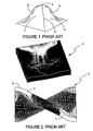
- Figures 1 illustrates a prior art roll tooth 1 of the kind used in the prior art method disclosed in EP0891234 (which is owned by the current applicant) for forming a projection 2 in sheet material 3 as shown in Figure 2 .
- the roll tooth 1 is a cross cut involute gear form having four flanks 4 merging to a substantially flat peak 5.
- the forming rolls (not shown) will include a plurality of such teeth 1, wherein the teeth 1 on adjacent rolls (not shown) intermesh to deform the sheet material 3.
- the geometry and density of the teeth 1 across the surface of the rolls is dependent upon specific requirements of the application. For example, an increase in the depth of intermeshing and/or an increase in the density of teeth 1 will result in a greater degree of work hardening as well as a greater reduction in overall length of the material.
- FIG. 3 there is shown a fragment of formed sheet material 10 comprising mild steel having on both of its faces a large number of projections 11 and depressions 12, each projection 11 at one face corresponding to a depression 12 at the other face.
- the projections 11 and depressions 12 are substantially square in shape with rounded corners.
- the projections 11 and depressions 12 at one face are arranged in rectilinear rows R11 and columns C11, wherein each row R11 and each column C11 comprises alternating projections 11 and depressions 12.
- rows R12, R13 of projections 11 and depressions 12 which extend along a line between the directions of the rows R11 and columns C11.
- the rows R12, R13 extend at 45° to the rows R11 and the columns C11 in this embodiment. These rows are referred to hereinafter as helical rows R12, R13.
- the angle can range from 0° to 180°.
- Adjacent projections 11 and depressions 12 are sufficiently close to one another for there to be no substantially flat areas of sheet material between them.
- the sheet material 10 as viewed in any cross-section which is generally perpendicular to the nominal or actual plane of the sheet material 10 is undulatory, thereby resulting in an effective thickness, or amplitude A, which is greater than the base gauge G of the material.
- the formed sheet material 10 illustrated in Figure 3 is formed by the process illustrated in Figure 4 .
- plain or base sheet material 17 having a base gauge G is drawn from a coil (not shown) and passes between a pair of rolls 18 and 19, each of which has at its periphery a number of teeth 30.
- the rolls 18, 19 are rotated about respective parallel axes 20 and 21 and the base sheet material 17 is engaged and deformed by the teeth 30 of the rolls 18, 19.
- Each tooth 30 pushes a part of the base sheet material 17 into a gap between teeth 30 on the other roll 18, 19 to form a projection 11 facing that other roll 18, 19 and a corresponding depression 12 facing the one roll 18, 19, thereby providing the formed sheet material 10.
- the overall thickness of the base sheet material 17 is increased by the presence of projections 11 on both of its faces and providing an effective thickness, or amplitude A, in the formed sheet material 10.
- the sheet material 10 may then pass between further roll pairs 22, 23 and 24 to shape the formed sheet material 10 into a channel section 27 in this embodiment.
- Other elongate shaped members may also be formed.
- the roll pair 18 and 19 and the further roll pairs 22, 23 and 24 are all driven by common drive means 25 of known form and preferably including an electric motor 26.
- the roll pairs 18 and 19, 22, 23, 24 are driven at substantially the same peripheral speed so that the base sheet material 17 passes continuously and at the same speed between the rolls 18 and 19 as the formed sheet material 10 passes between the subsequent further roll pairs 22, 23, 24.
- the formed sheet material 10 After the formed sheet material 10 has been shaped into a channel or other section 27, it may be cut into lengths (not shown) for transportation and use.
- Both of the rolls 18, 19 have substantially the same form with a first dimension, or axial length in this embodiment, and a second dimension orthogonal to the first, or circumferential dimension in this embodiment.
- Each roll 18, 19 includes a plurality of identical teeth 30 on its periphery, each of which teeth 30 includes a tooth forming portion 30a as shown in Figure 5 .
- the teeth 30 are arranged in a plurality of rows which correspond to the rows R11, R12, R13 and columns C11 of the formed sheet material. It will be appreciated that the helical rows R12, R13 of teeth 30 extend along lines which extend between lines lying along the first and second dimensions. In this embodiment, the helical rows (not shown) are inclined to the axis 20, 21 of the roll 18, 19 at an angle of 45°.
- Each tooth forming portion 30 is formed integrally with a tooth base portion (not shown) which in turn is formed integrally or otherwise secured to the periphery of one of the rolls 18, 19. It will be appreciated that the tooth base portions (not shown) are sized and dimensioned such that they do not impede deformation of the material in use.
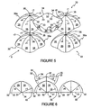
- the first embodiment of tooth forming portions 30a have a geometry and cooperating layout as illustrated in part in Figures 5 to 8 .
- Each tooth forming portion 30a includes a base plane 31 which is substantially square in shape having rounded corners 32 and a smoothed depression 33 at the mid point of each side edge 34, thereby forming a four lobed shape.
- the side surfaces 35 of the tooth forming portion 30 project upward from the side edges 34 of the base 31 and curve toward a common smoothed apex 36, thus forming a rounded sheet engaging surface. It will be appreciated that there are no sharp corners present on the tooth forming portions 30a.
- the features of the shape of the tooth forming portion 30a are defined by a series of radii r 1 , r 2 , r 3 , r 4 , each of which has a constant radius of curvature in this embodiment.
- the first and third radii r 1 , r 3 are different from the second and fourth radii r 2 , r 4 in this embodiment.
- the term "radius” refers to the distance between the centre of the tooth base plane 31 and the tooth face 35 as measured along an imaginary plane extending in the direction of the radius r 1 , r 2 , r 3 , r 4 (as shown more clearly in Figure 6 ) whilst the term “radius of curvature” refers to the actual surface radius at a specific point on the surface of the tooth forming portion 30a.
- a "radius” r 1 , r 2 , r 3 , r 4 may be a compound radius of curvature having two or more radii of curvature blended together.
- the "direction" of a radius r 1 , r 2 , r 3 , r 4 refers to the direction in which the plane of that radius r 1 , r 2 , r 3 , r 4 extends.
- the first and third radii r 1 , r 3 are orthogonal to one another and each extends in a direction between the first and second directions (i.e. between the axial and circumferential directions of the rolls 18, 19). As is shown, r 1 , r 3 both extend at 45° to the first direction in this embodiment.
- the second and fourth radii r 2 , r 4 extend respectively along the axial direction and circumferential (i e. rolling) direction.
- the pitch P between adjacent teeth 30 is equal in this embodiment along both the rectilinear rows R11 and columns C11.
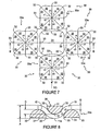
- the sheet material 10 is passed through the rolls 18, 19 in the rolling direction RD (shown in Figure 7 ).
- Each tooth forming portion 30 from one of the rolls 18, 19 moves into and out of alignment with the space between adjacent tooth forming portions 30 in the other of the rolls 18, 19 as shown more clearly in Figures 5 to 8 .
- the amplitude A of the formed sheet material 10 is a function of the depth D of penetration, or overlap, between the forming portions 30a, which in turn is a function of the separation of the rolls 18, 19.
- the spacing and geometry of the teeth 30 in this embodiment are such that the apex or peak of a projection 11 being formed by one of the teeth 30 on one of the rolls 18, 19 is free from contact with other the roll 18, 19. This can be seen, for example, in Figure 8 .
- the amplitude A of the sheet material leaving the rolls 18 and 19 is preferably between 1.5 to 4, say 2 and 3, times the base gauge G of the sheet material. However, it will be appreciated that subsequent shaping of the sheet material by the roll pairs 22, 23 and 24 can reduce the amplitude A of the formed sheet material 10.
- the improvements in physical properties of sheet material of the kind specified are mainly attributed to the increase in effective thickness of the sheet material and the strain hardening effect which is a consequence of the plastic deformation of the material. It is therefore desirable to maximise the effective thickness or amplitude A of the formed material 10 and to maximise both the magnitude and area of plastic strain. Increasing the amplitude A will increase the magnitude of plastic strain and decreasing the pitch P will increase the area of plastic strain because of an increase in projection density.
- a tooth form which enables a balance to be struck between these competing factors, is achieved by providing a rounded sheet engaging surface having a radius of curvature equal to the preferable surface radius R in some areas while the radius of curvature in other areas is adjusted to prevent pinching. Material pinching occurs in the regions where there is the least distance between intermeshing teeth. In the case of the first embodiment of tooth forming portion 30a, this is in the direction of the rectilinear rows R11 and columns C11 (i.e. direction of r 2 and r 4 ).
- the radii r 1 , r 3 of the sheet engaging surface have a radius of curvature equal to the preferable surface radius R, while the radii r 2 , r 4 gradually decrease from the peak to the base portion (not shown).
- This provides a profile which allows for a reduced pitch P to maximise the strained area, while providing a degree of extra clearance to avoid pinching the material.
- the pitch P is at least 2.5 times, preferably at least 3 times, for example 3.32 times, the preferable surface radius R (i.e. the first and third radii r 1 , r 3 in this embodiment) the level of strain can be maximised.
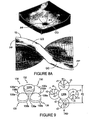
- FIG. 8a shows a representation of the plastic strain of a part of the sheet material 10 formed using the tooth geometry shown in Figures 5 to 8 . As shown in Figure 8a , there is a continuous area of peak plastic strain PP around the apex of the projection 11, while the plastic strain in the quaquaversal region QQ surrounding the area PP decreases moving away from that region. The sheet material is thinned by less that 25%.
- the base of the depression 12 includes four radii dr 1 , dr 2 , dr 3 and dr 4 , which correspond generally to the four radii r 1 , r 2 , r 3 and r 4 of the sheet engaging surface of the tooth.
- Figure 9 shows a second embodiment of tooth 130 which includes a forming portion 130a of hemispherical form and a cylindrical base portion 130b formed integrally with the forming portion 130a.
- all radii r 1 , r 2 , r 3 and r 4 are equal to the preferable surface radius R and the pitch P 2 is such that no material pinching occurs. It will be appreciated that the pitch P 2 required to prevent material pinching will be greater for this embodiment since the second and fourth radii r 2 , r 4 are equal to the first and third radii r 1 , r 3 .
- Figure 10 shows a third embodiment of tooth 230 which includes a forming portion 230a formed integrally with a base portion 230b that is generally square in plan with rounded corners.
- the first and third radii r 1 , r 3 in this embodiment are both equal to the preferable surface radius R, whereas the second and fourth radii r 2 , r 4 each comprise a compound radius gradually decreasing toward the base portion 230b to provide suitable clearance and thereby reduce the potential for material pinch.
- This tooth form 230 allows for a reduced pitch P 3 with respect to the pitch P 2 of the second embodiment, thereby increasing the density of projections 11 and improving the proportion of the formed sheet material 10 which is strain hardened.
- Figure 11 shows a fourth embodiment of tooth 330 which includes a forming portion 330a formed integrally with a base portion 330b that is also generally square in plan with rounded corners.
- the first and third radii r 1 , r 3 in this embodiment are both equal to the preferable surface radius R at or adjacent to the peak 311a of the tooth 330 and comprise a compound radius gradually decreasing toward the base portion 330b.
- the second and fourth radii r 2 , r 4 have a single radius of curvature and are smaller than the first and third radii r 1 , r 3 to provide suitable clearance and thereby reduce the potential for material pinch.
- This tooth form 330 allows for a reduced pitch P 4 with respect to the pitch P 2 of the second embodiment since the size of the base portion 330b can be reduced for a given preferable surface radius R, thus increasing the worked area of the sheet material 10.
- Figure 12 shows a fifth embodiment of tooth 430 which includes a forming portion 430a formed integrally with a base portion 430b that is also generally square in plan with rounded corners.
- the first and third radii r 1, r 3 in this embodiment are both equal to the preferable surface radius R at or adjacent to the peak 411a of the tooth 430 and comprise a compound radius gradually decreasing toward the base portion 430b.
- the second and fourth radii r 2 , r 4 each comprise a compound radius gradually decreasing toward the base portion 430b to provide a region having a suitable clearance and thereby reduce the potential for material pinch.
- the four compound radii r 1 , r 2 , r 3 , r 4 of the tooth form 430 provide maximum flexibility for optimising the balance between the degree of work hardening and avoiding material pinch.
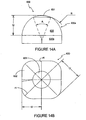
- Figures 13 , 14A and 14B show a sixth embodiment of tooth 630 which includes a forming portion 630a formed integrally with a base portion 630b that is generally square in plan with rounded corners. All of the radii r 1 , r 2 , r 3 , r 4 in this embodiment are equal to the preferable surface radius R at and adjacent to the peak 611 a of the tooth 430 to provide a part spheroidal surface 631 and comprise a compound radius gradually decreasing toward the base portion 430b extending from and blended with the part spheroidal surface 631.
- the second and fourth radii r 2 , r 4 each comprise a compound radius which gradually decreases toward the base portion 430b by a steeper gradient than the first and third radii r 1 , r 3 , thereby providing a region having a suitable clearance to reduce the potential for material pinch.
- the part spheroidal surface 631 or tip area 631 is defined by a conical segment with an angle A between 0 and 180°. Clearly, if the angle A approaches 180° then the tooth form 160 will approach that of Figure 9 .
- the shaped sheet material 27 which results from the process illustrated in Figure 4 is suitable for use on its own or in the form of a structural member 27a, 27b as shown in Figures 15 and 16 , for example a post or a beam.
- sheet material 10 of channel form 27a, 27b is particularly suitable, the channel 27a, 27b having flanges 270a, 271a, 270b and a web 272a, 272b which maintains the flanges 270a, 271a, 270b a predetermined distance apart.
- the surfaces of the flanges 270a, 271 a, 270b and the web 272a, 272b include rows (R11, R12, R13) of projections 11 and depressions 12.
- projections 11 and depressions 12 may be required on only a part of the surface of the sheet material 10.
- the invention is applicable with especial advantage to studs 27a, 27b used in stud and panel partitions and to the channel lengths 27b in which end portions of the studs 27a, 27b are received.
- generally flat material or section other than a channel 27 are useful, for example C-sections, U-sections, Z-sections, I sections and so on.
- Sheet material of the kind specified formed in accordance with the present invention is much stiffer than the plain sheet material from which it is formed. In particular, the bending strength of such material increases dramatically.
- a specimen of sheet material having a base gauge G of 0.45mm was formed using a tool comprising the tooth form shown in Figure 10 .
- the pitch of the teeth on the tool was 5.1mm, the first and third radii r 1 , r 3 had a constant radius of curvature of 1.5mm, while the second and fourth radii r 2 , r 4 had a composite radius of curvature.
- the sheet material was formed with an amplitude A of 2.5 times the base gauge G of the material 17 with a proportion of significant plastic strain of 70% and material thinning of 15%.
- the formed sheet material 10 resulted in a 33% increase in bending strength over the plain sheet material from which it was formed, as measured by a 5mm displacement three point bending test.
- a further specimen of sheet material having a base gauge G of 0.45mm was formed using a tool comprising the same tooth form and having the same pitch as in Example 1.
- the sheet material was formed with an amplitude A of 3 times the base gauge G of the material 17 with a proportion of significant plastic strain of 88% and material thinning of 23%.
- the formed sheet material 10 resulted in a 36% increase in bending strength over the plain sheet material from which it was formed, as measured by a 5mm displacement three point bending test.
- a specimen of sheet material having a base gauge G of 0.7mm was formed using a tool comprising the same tooth form and having the same pitch as in Example 1.
- the sheet material was formed with an amplitude A of 2 times the base gauge G of the material 17 with a proportion of significant plastic strain of 88% and material thinning of 11%.
- the formed sheet material 10 resulted in a 48% increase in bending strength over the plain sheet material from which it was formed, as measured by a 5mm displacement three point bending test.
- a further specimen of sheet material having a base gauge G of 0.7mm was formed using a tool comprising the same tooth form and having the same pitch as in Example 1.
- the sheet material was formed with an amplitude A of 2.5 times the base gauge G of the material 17 with a proportion of significant plastic strain of 96% and material thinning of 22%.
- the formed sheet material 10 resulted in a 62% increase in bending strength over the plain sheet material from which it was formed, as measured by a 5mm displacement three point bending test.
- a specimen of sheet material having a base gauge G of 2mm was formed using a tool comprising the tooth form shown in Figure 9 .
- the pitch of the teeth on the tool was 9.5mm and the first, second, third and fourth radii r 1 , r 2, r 3 , r 4 all had a constant radius of curvature of 2.5mm.
- the sheet material was formed with an amplitude A of 1.8 times the base gauge G of the material 17 with a proportion of significant plastic strain of 76% and material thinning of 24%.
- the formed sheet material 10 resulted in a 35% Increase in bending strength over the plain sheet material from which it was formed, as measured by a 5mm displacement three point bending test.
- the forming tool or tools need not comprise inter-engaging rolls. Any suitable tool may be used such as a press or other stamping means for example.
- roll pair 18, 19 There may be a substituted for the roll pair 18, 19 a pair of rolls which are not identical, for example, one having square teeth (not shown) and the other having elongated teeth (not shown).
- helical rows are inclined at 45 degrees relative to the axis of the rolls, they may be inclined at any angle and/or they need not be arranged in helical rows.
- the tool need not be rolls, could be, for example, a block with a flat face and/or substantially planar
- the sheet material is preferably mild steel, which may be galvanised or otherwise coated for protection against corrosion. Modification of initially plain, galvanised mild steel sheet in the manner hereinbefore described leaves the protective coating intact.
- the base gauge G of the plain sheet material is typically within the range 0.3 to 3mm.
- the present invention can be used to form material with a base gauge G of 3mm whilst still showing improved strength and no noticeable material pinching.
- the pitch P between adjacent teeth 30 in rows R11 may be different from the pitch P in the columns C11.
- sheet material embraces generally flat material, for example such as that which is described in the aforesaid European patent applications and products made by bending or shaping generally flat sheet material, examples of which products are shown in Figures 9 and 10 and mentioned in our published international patent application published as WO82/03347 .
Landscapes
- Engineering & Computer Science (AREA)
- Architecture (AREA)
- Civil Engineering (AREA)
- Structural Engineering (AREA)
- Mechanical Engineering (AREA)
- Shaping Of Tube Ends By Bending Or Straightening (AREA)
- Bending Of Plates, Rods, And Pipes (AREA)
- Forging (AREA)
- Inorganic Compounds Of Heavy Metals (AREA)
- Blow-Moulding Or Thermoforming Of Plastics Or The Like (AREA)
- Heat Treatment Of Steel (AREA)
- Moulds For Moulding Plastics Or The Like (AREA)
- Manufacturing Of Steel Electrode Plates (AREA)
- Lubricants (AREA)
- Laminated Bodies (AREA)
- Formation And Processing Of Food Products (AREA)
- Dental Tools And Instruments Or Auxiliary Dental Instruments (AREA)
Abstract
Description
- The present invention relates generally to sheet material and more specifically to sheet material having projections on its surfaces, according to the preamble of claim 1 and to a method for forming sheet material according to the preamble of claim 9 (see for example
EP-B-0891234 ). - As referred to herein, sheet material of the kind specified refers to sheet material having on both of its faces a plurality of rows of projections, each projection having been formed by deforming the sheet material locally to leave a corresponding depression at the opposite face of the material. This deformation is effected by a forming tool and results in both plastic strain hardening and in an increase of the effective thickness thereof. Sheet material of the kind specified is stiffer than the plain sheet material from which it is formed and the mass of material required for a particular duty can be reduced by using sheet material of the kind specified in place of plain sheet material.
- The magnitude and distribution of plastic strain exerted on the sheet material depends on a number of factors including, inter alia, the depth of penetration of the forming portions of the tool and the geometry of the forming portions.
- An further example of sheet material of the kind specified is disclosed in
EP0674551 , which is owned by the current applicant, wherein the sheet material is provided with the relative positions of the projections and depressions such that lines drawn on a surface of the material between adjacent rows of projections and depressions are non-linear. The projections are formed by forming tools having teeth with four flanks, wherein each flank faces a direction between the axial and circumferential directions of the rolls. - A further factor which affects the magnitude and distribution of plastic strain in such an arrangement is the layout or concentration of teeth in the forming tool.
- According to a first aspect of the invention there is provided sheet of cold rolled material having on both of its surfaces rows of projections and rows of depressions, the projections on one surface corresponding with the depressions on the other surface the relative positions of the projections and depressions being such that lines drawn on a surface of the sheet between adjacent rows of projections are non-rectilinear, the sheet having a base gauge G, characterised in that each projection has a substantially continuous region of peak plastic strain at or about its apex and is thinned by no more than 25% of its base gauge G.
- Preferably, the base of each depression may comprise two or more different radii of curvature.
- The projections and/or depressions are preferably arranged in rectilinear and/or helical rows. The base of each depression may comprise a first radius dr1, for example in a first direction. The depressions may comprise a second radius dr2, for example in a second and/or longitudinal and/or rolling direction with respect to a length of the sheet material. The first direction may be different from the second direction, for example at 45 degrees therefrom. The radius of curvature along the first radius may be different from the radius of curvature along the second radius.
- The depressions may further comprise a third radius dr3, for example in a third direction orthogonal to the first direction. The depressions may further comprise a fourth radius dr4, for example in a fourth direction orthogonal to the second direction. The first and third radii dr1 and dr3 may be equal, with the second radius dr2 and/or dr4 being different therefrom, for example less therethan, or the same thereas.
- The pitch P between adjacent depressions or between adjacent projections in each row may be at least 2.5, say 3, times the radius of curvature along the first radius dr1. Additionally or alternatively, the pitch P is preferably between 2.5 and 3.9, for example about 3.3, say 3.32, times the radius of curvature along the first radius dr1.
- The sheet material may comprise an amplitude A. The height of projections which is sufficient to ensure that lines drawn on a surface of the material between adjacent rows of projections and depressions are not rectilinear depends upon the pitch of the projections and the pitch of the depressions in the rows.
- As viewed in any cross-section in a plane which is generally perpendicular to the sheet material, the amplitude A is preferably substantially greater than the base gauge G of the material. In all such cross sections, sheet material in accordance with the invention is preferably undulatory and there is more preferably no place where the material can be cut along a straight line and the resulting cross section of the material will be rectilinear.
- The amplitude A is preferably between 1.5 to 4, say 2 and 3, times the base gauge G. The base gauge G may be 2mm or greater. The base gauge G is preferably between 0.2 mm and 3.0 mm, for example 0.7 mm or 1.5mm.
- The plastic strain of the material is preferably 0.05 or more. The proportion of sheet material which is subjected to significant plastic strain, that is to say plastically strained to a value of 0.05 or more, is preferably at least 65% and more preferably over 80%, for example 90% to 100%.
- The sheet material may comprise steel, for example, mild steel and may be galvanised. Alternatively, the sheet material may comprise any other material capable of strain hardening and/or plastic deformation.
- The sheet material may comprise a profile or shaped cross-section such as a channel section or the like for use as a, or as part of a, partition or channel stud. The projections may be formed over all or part of the shaped section.
- According to a further aspect of the invention, there is provided a method of forming sheet material according to
claim 12. - The method may further comprise shaping the formed sheet material, for example into a channel section.
- The method may comprise urging the material such that the apex or peaks of the projections are free from contact with the other tool during forming.
- The method may comprise subjecting the sheet material to a plastic strain of 0.05 or more across at least 65% of the formed area thereof.
- The clearance between the teeth on one tool and the teeth on the other tool during forming may be at least 1.1 times the base gauge of the plain sheet material.
- A tool suitable for carrying out the method according to the invention may comprise rows of teeth on its outer surface, each tooth comprising a rounded sheet engaging surface.
- The rounded sheet engaging surface of each tooth may have a radius of curvature, the pitch between adjacent teeth in a row being between 2.5 and 3.9 times the radius of curvature.
- Preferably, there is also a minimum clearance, in use, between the peak of each tooth on the one tool and the root surface of the other tool, for example to ensure material to be formed is not pinched therebetween.
- The pair of tools may form part of an apparatus.
- The apparatus may further comprise shaping means for shaping the sheet material. The shaping means may comprise a further pair of rollers and may be arranged to shape the formed sheet material, for example into a channel section.
- Preferably, the pitch P is between 3 and 3.5, for example 3.32, times the radius of curvature R.
- The radius of curvature R is preferably at least equal to the base gauge G of a sheet material to be formed and more preferably at least 1.1 times the base gauge G, for example at least 2 times the base gauge G and/or less than 3.33 times the base gauge. Thus, the pitch is preferably between 2.5 and 13 times the base gauge G, for example between 2.75 and 7.8 times the base gauge and more preferably at least 3.65 times the base gauge G.
- Each tooth may have a rounded sheet engaging surface with a first radius r1 in a first direction and/or a second radius r2 in a second direction along the rows. The first direction may be at an acute angle in relation to the second direction. The second radius r2 may be less than or equal to the first radius r1.
- As used herein, the term "radius" refers to the distance between the centre of the tooth base plane and the tooth face as measured along an imaginary plane extending in the direction of the radius r1, r2, r3, r4 whilst the term "radius of curvature" refers to the actual surface radius at a specific point on the surface of the tooth forming portion. Thus, a "radius" r1, r2, r3, r4 may be a compound radius of curvature having two or more radii of curvature blended together.
- For the avoidance of doubt, the "direction" of a radius r1, r2, r3, r4 refers to the direction in which the plane of that radius r1, r2, r3, r4 extends.
- The pitch P between adjacent teeth in a row may be at least 3.3, for example at least 3.32, times the first and/or second radii r1, r2. Preferably, the pitch P between adjacent teeth in a row is at least 3.3, for example at least 3.32, times the second radius r2 measured at the point of the tooth nearest the adjacent tooth from the other tool. It is postulated that this arrangement provides sufficient clearance to avoid material pinching in use.
- Preferably, the radius of curvature R is less than or equal to 6.7mm and/or the pitch is less than 15.6mm such as between 5mm and 15.6mm, for example between 5mm and 7.8mm.
- The tool or tools may comprise a first dimension and a second dimension, for example where the second dimension is orthogonal to the first dimension. The rows may extend in the direction of the first and/or the second dimensions. Alternatively, the rows may extend in a direction between the first and second dimensions.
- The tool or tools may comprise cylindrical rolls, for example which are rotatable about respective axes, which axes may be parallel to one another. The teeth may be arranged in helical rows. Each tooth may have a sheet engaging forming portion which is substantially free of sharp corners and/or comprises the sheet engaging surface. The first dimension may comprise a circumferential dimension and/or the second dimension may comprise an axial dimension. In this embodiment there is preferably a minimum clearance, in use, between the peak of each tooth on the one tool and the root diameter of the other tool, for example to ensure material to be formed is not pinched therebetween.
- The sheet engaging surface is preferably free of sharp corners. The teeth may comprise forming portions free of sharp corners.
- Each tooth may further comprise a third radius r3, for example in the third direction orthogonal to the first direction, and/or a fourth radius r4, for example in a fourth direction orthogonal to the second direction. The third radius r3 may be equal to the first radius r1 and/or the fourth radius r4 may be equal to the second radius r2.
- The tooth may have compound or blended radii of curvatures, such that the radius of curvature on one part of the tooth's periphery blends smoothly and continuously into a second radius of curvature on another part of the tooth's periphery.
- The pitch P and/or the radii r1, r2, r3, r4 and/or the spacing of the rolls are preferably selected such that the tooth forming portions cause the aforementioned plastic strain and/or material thinning to the sheet material, in use.
- One embodiment of the invention will now be described, by way of example only, with reference to the accompanying drawings, in which:
-
Figure 1 is a perspective view of a tooth used in the method according to the prior art; -
Figure 2 is a representation of the strain distribution across a projection formed in sheet material using the tooth ofFigure 1 ; -
Figure 3 is a plan view of a fragment of one embodiment of sheet material according to the invention; -
Figure 4 is a diagrammatical illustration of the forming of sheet material according to an embodiment of the method of the invention; -
Figure 5 is a perspective view of the cooperation of a group of teeth having a first embodiment of tooth forming portions; -
Figure 6 is a side view of the tooth forming portions ofFigure 5 from direction X; -
Figure 7 is a plan view of the tooth forming portions ofFigure 5 ; -
Figure 8 is a cross-section view along line B-B ofFigure 7 showing sheet material being formed between the tooth forming portions; -
Figure 8A is a representation of the strain distribution across a projection formed in sheet material using the tooth ofFigure 8 ; -
Figure 9 shows a second embodiment of tooth forming portions; -
Figure 10 shows a third embodiment of tooth forming portions; -
Figure 11 shows a fourth embodiment of tooth forming portions; -
Figure 12 shows a fifth embodiment of tooth forming portions; -
Figure 13 shows a sixth embodiment of tooth forming portions; -
Figure 14A is a cross-sectional view of one of the tooth forming portions ofFigure 13 ; -
Figure 14B is a top view of one of the tooth forming portions ofFigure 13 ; -
Figure 15 is a perspective view of sheet material shaped into a first embodiment of channel section; and - Figure 18 is a perspective view of sheet material shaped into a second embodiment of channel section.
-
Figures 1 illustrates a prior art roll tooth 1 of the kind used in the prior art method disclosed inEP0891234 (which is owned by the current applicant) for forming aprojection 2 insheet material 3 as shown inFigure 2 . The roll tooth 1 is a cross cut involute gear form having fourflanks 4 merging to a substantiallyflat peak 5. The forming rolls (not shown) will include a plurality of such teeth 1, wherein the teeth 1 on adjacent rolls (not shown) intermesh to deform thesheet material 3. - The geometry and density of the teeth 1 across the surface of the rolls (not shown) is dependent upon specific requirements of the application. For example, an increase in the depth of intermeshing and/or an increase in the density of teeth 1 will result in a greater degree of work hardening as well as a greater reduction in overall length of the material.
- We have observed through extensive experimentation that the practical range of depth and/or density of teeth 1 on the roll (not shown) for producing useful sheet material of the kind specified is also limited by the resulting degree of material thinning, which worsen the mechanical properties of the material. The equipment and methods of producing sheet material of the kind specified therefore requires a balance between the density and intermeshing of the teeth versus the degree of material thinning in order to optimise the forming process.
- On further Investigation, we have surprisingly determined that the
sharp corners 6 between theflanks 4, which are formed as a result of the manufacturing process, causeareas 7 of peak plastic strain. - As a result, a higher degree of work hardening and thinning of the material is experienced in these
areas 7. The resulting strain distribution is illustrated inFigure 2 . Without wishing to be limited by any particular theory we now postulate that difficulties in forming sheet material of the kind specified using a relatively thick sheet material, for example having a thickness above 1.5mm, may be attributed to this phenomenon. - It is from these surprising realisations that we have conceived and developed the present invention.
- Referring now to
Figure 3 , there is shown a fragment of formedsheet material 10 comprising mild steel having on both of its faces a large number ofprojections 11 anddepressions 12, eachprojection 11 at one face corresponding to adepression 12 at the other face. Theprojections 11 anddepressions 12 are substantially square in shape with rounded corners. - The
projections 11 anddepressions 12 at one face are arranged in rectilinear rows R11 and columns C11, wherein each row R11 and each column C11 comprises alternatingprojections 11 anddepressions 12. There are also alternating respective rows R12, R13 ofprojections 11 anddepressions 12 which extend along a line between the directions of the rows R11 and columns C11. The rows R12, R13 extend at 45° to the rows R11 and the columns C11 in this embodiment. These rows are referred to hereinafter as helical rows R12, R13. The angle can range from 0° to 180°. -
Adjacent projections 11 anddepressions 12 are sufficiently close to one another for there to be no substantially flat areas of sheet material between them. Thus, thesheet material 10 as viewed in any cross-section which is generally perpendicular to the nominal or actual plane of thesheet material 10 is undulatory, thereby resulting in an effective thickness, or amplitude A, which is greater than the base gauge G of the material. - The formed
sheet material 10 illustrated inFigure 3 is formed by the process illustrated inFigure 4 . In this process, plain orbase sheet material 17 having a base gauge G is drawn from a coil (not shown) and passes between a pair ofrolls teeth 30. Therolls parallel axes base sheet material 17 is engaged and deformed by theteeth 30 of therolls tooth 30 pushes a part of thebase sheet material 17 into a gap betweenteeth 30 on theother roll projection 11 facing thatother roll depression 12 facing the oneroll sheet material 10. Thus, the overall thickness of thebase sheet material 17 is increased by the presence ofprojections 11 on both of its faces and providing an effective thickness, or amplitude A, in the formedsheet material 10. - From the
roll pair sheet material 10 may then pass between further roll pairs 22, 23 and 24 to shape the formedsheet material 10 into achannel section 27 in this embodiment. Other elongate shaped members (not shown) may also be formed. - The
roll pair electric motor 26. The roll pairs 18 and 19, 22, 23, 24 are driven at substantially the same peripheral speed so that thebase sheet material 17 passes continuously and at the same speed between therolls sheet material 10 passes between the subsequent further roll pairs 22, 23, 24. - After the formed
sheet material 10 has been shaped into a channel orother section 27, it may be cut into lengths (not shown) for transportation and use. - Both of the
rolls roll identical teeth 30 on its periphery, each of whichteeth 30 includes atooth forming portion 30a as shown inFigure 5 . Theteeth 30 are arranged in a plurality of rows which correspond to the rows R11, R12, R13 and columns C11 of the formed sheet material. It will be appreciated that the helical rows R12, R13 ofteeth 30 extend along lines which extend between lines lying along the first and second dimensions. In this embodiment, the helical rows (not shown) are inclined to theaxis roll - Each
tooth forming portion 30 is formed integrally with a tooth base portion (not shown) which in turn is formed integrally or otherwise secured to the periphery of one of therolls - The first embodiment of
tooth forming portions 30a have a geometry and cooperating layout as illustrated in part inFigures 5 to 8 . Eachtooth forming portion 30a includes abase plane 31 which is substantially square in shape having roundedcorners 32 and a smootheddepression 33 at the mid point of eachside edge 34, thereby forming a four lobed shape. The side surfaces 35 of thetooth forming portion 30 project upward from the side edges 34 of thebase 31 and curve toward a common smoothedapex 36, thus forming a rounded sheet engaging surface. It will be appreciated that there are no sharp corners present on thetooth forming portions 30a. - The features of the shape of the
tooth forming portion 30a are defined by a series of radii r1, r2, r3, r4, each of which has a constant radius of curvature in this embodiment. However, the first and third radii r1, r3 are different from the second and fourth radii r2, r4 in this embodiment. - As used herein, the term "radius" refers to the distance between the centre of the
tooth base plane 31 and thetooth face 35 as measured along an imaginary plane extending in the direction of the radius r1, r2, r3, r4 (as shown more clearly inFigure 6 ) whilst the term "radius of curvature" refers to the actual surface radius at a specific point on the surface of thetooth forming portion 30a. Thus, a "radius" r1, r2, r3, r4 may be a compound radius of curvature having two or more radii of curvature blended together. - For the avoidance of doubt, the "direction" of a radius r1, r2, r3, r4 refers to the direction in which the plane of that radius r1, r2, r3, r4 extends.
- The first and third radii r1, r3 are orthogonal to one another and each extends in a direction between the first and second directions (i.e. between the axial and circumferential directions of the
rolls 18, 19). As is shown, r1, r3 both extend at 45° to the first direction in this embodiment. The second and fourth radii r2, r4 extend respectively along the axial direction and circumferential (i e. rolling) direction. The pitch P betweenadjacent teeth 30 is equal in this embodiment along both the rectilinear rows R11 and columns C11. - In use, the
sheet material 10 is passed through therolls Figure 7 ). Eachtooth forming portion 30 from one of therolls tooth forming portions 30 in the other of therolls Figures 5 to 8 . As can be seen fromFigure 8 , the amplitude A of the formedsheet material 10 is a function of the depth D of penetration, or overlap, between the formingportions 30a, which in turn is a function of the separation of therolls - The spacing and geometry of the
teeth 30 in this embodiment are such that the apex or peak of aprojection 11 being formed by one of theteeth 30 on one of therolls roll Figure 8 . - The amplitude A of the sheet material leaving the
rolls sheet material 10. - As mentioned above, the improvements in physical properties of sheet material of the kind specified are mainly attributed to the increase in effective thickness of the sheet material and the strain hardening effect which is a consequence of the plastic deformation of the material. It is therefore desirable to maximise the effective thickness or amplitude A of the formed
material 10 and to maximise both the magnitude and area of plastic strain. Increasing the amplitude A will increase the magnitude of plastic strain and decreasing the pitch P will increase the area of plastic strain because of an increase in projection density. - However, the greater the magnitude of plastic strain, the greater the extent of material thinning, which adversely affects the physical properties of the sheet material.
- We have determined that there is a preferable or optimum sheet engaging surface radius R which provides a balance between maximising work hardening and minimising the material thinning.
- However, as mentioned above, it is desirable to minimise the pitch P in order to maximise the area of plastic strain. It has been observed that the sheet material is 'pinched' when the clearance between adjacent forming
portions 30a approaches and is less than the base gauge G in use. Whilst material pinch is beneficial in terms of plastic strain and therefore strain hardening of the formed material, it can result in local thinning of the sheet material and it causes issues in manufacture due to excessive loads and roll wear issues. It is therefore preferable to avoid material pinch. - A tooth form which enables a balance to be struck between these competing factors, is achieved by providing a rounded sheet engaging surface having a radius of curvature equal to the preferable surface radius R in some areas while the radius of curvature in other areas is adjusted to prevent pinching.
Material pinching occurs in the regions where there is the least distance between intermeshing teeth. In the case of the first embodiment oftooth forming portion 30a, this is in the direction of the rectilinear rows R11 and columns C11 (i.e. direction of r2 and r4). - Accordingly, in this embodiment the radii r1, r3 of the sheet engaging surface have a radius of curvature equal to the preferable surface radius R, while the radii r2, r4 gradually decrease from the peak to the base portion (not shown). This provides a profile which allows for a reduced pitch P to maximise the strained area, while providing a degree of extra clearance to avoid pinching the material.
- We have determined that by ensuring that the pitch P is at least 2.5 times, preferably at least 3 times, for example 3.32 times, the preferable surface radius R (i.e. the first and third radii r1, r3 in this embodiment) the level of strain can be maximised.
- The surface radius along the radii r1, r2, r3 and r4 should be at least equal to the base gauge G, preferably 1.1 or more times the base gauge G, of the sheet material in order to ensure a relatively even strain distribution throughout the
projection 11 and to minimise thinning.Figure 8a shows a representation of the plastic strain of a part of thesheet material 10 formed using the tooth geometry shown inFigures 5 to 8 . As shown inFigure 8a , there is a continuous area of peak plastic strain PP around the apex of theprojection 11, while the plastic strain in the quaquaversal region QQ surrounding the area PP decreases moving away from that region. The sheet material is thinned by less that 25%. - The base of the
depression 12 includes four radii dr1, dr2, dr3 and dr4, which correspond generally to the four radii r1, r2, r3 and r4 of the sheet engaging surface of the tooth. - In order to further demonstrate the flexibility of the invention, reference is made to the further tooth forms shown in
Figures 9 to 13 . -
Figure 9 shows a second embodiment oftooth 130 which includes a formingportion 130a of hemispherical form and acylindrical base portion 130b formed integrally with the formingportion 130a. In this case, all radii r1, r2, r3 and r4 are equal to the preferable surface radius R and the pitch P2 is such that no material pinching occurs. It will be appreciated that the pitch P2 required to prevent material pinching will be greater for this embodiment since the second and fourth radii r2, r4 are equal to the first and third radii r1, r3. -
Figure 10 shows a third embodiment oftooth 230 which includes a formingportion 230a formed integrally with abase portion 230b that is generally square in plan with rounded corners. The first and third radii r1, r3 in this embodiment are both equal to the preferable surface radius R, whereas the second and fourth radii r2, r4 each comprise a compound radius gradually decreasing toward thebase portion 230b to provide suitable clearance and thereby reduce the potential for material pinch. Thistooth form 230 allows for a reduced pitch P3 with respect to the pitch P2 of the second embodiment, thereby increasing the density ofprojections 11 and improving the proportion of the formedsheet material 10 which is strain hardened. -
Figure 11 shows a fourth embodiment oftooth 330 which includes a formingportion 330a formed integrally with abase portion 330b that is also generally square in plan with rounded corners. The first and third radii r1, r3 in this embodiment are both equal to the preferable surface radius R at or adjacent to the peak 311a of thetooth 330 and comprise a compound radius gradually decreasing toward thebase portion 330b. The second and fourth radii r2, r4 have a single radius of curvature and are smaller than the first and third radii r1, r3 to provide suitable clearance and thereby reduce the potential for material pinch. Thistooth form 330 allows for a reduced pitch P4 with respect to the pitch P2 of the second embodiment since the size of thebase portion 330b can be reduced for a given preferable surface radius R, thus increasing the worked area of thesheet material 10. -
Figure 12 shows a fifth embodiment oftooth 430 which includes a formingportion 430a formed integrally with abase portion 430b that is also generally square in plan with rounded corners. The first and third radii r1, r3 in this embodiment are both equal to the preferable surface radius R at or adjacent to thepeak 411a of thetooth 430 and comprise a compound radius gradually decreasing toward thebase portion 430b. The second and fourth radii r2, r4 each comprise a compound radius gradually decreasing toward thebase portion 430b to provide a region having a suitable clearance and thereby reduce the potential for material pinch. The four compound radii r1, r2, r3, r4 of thetooth form 430 provide maximum flexibility for optimising the balance between the degree of work hardening and avoiding material pinch. -
Figures 13 ,14A and 14B show a sixth embodiment oftooth 630 which includes a formingportion 630a formed integrally with abase portion 630b that is generally square in plan with rounded corners. All of the radii r1, r2, r3, r4 in this embodiment are equal to the preferable surface radius R at and adjacent to the peak 611 a of thetooth 430 to provide apart spheroidal surface 631 and comprise a compound radius gradually decreasing toward thebase portion 430b extending from and blended with thepart spheroidal surface 631. The second and fourth radii r2, r4 each comprise a compound radius which gradually decreases toward thebase portion 430b by a steeper gradient than the first and third radii r1, r3, thereby providing a region having a suitable clearance to reduce the potential for material pinch. - As shown more clearly in
Figures 14A and 14B , thepart spheroidal surface 631 ortip area 631 is defined by a conical segment with an angle A between 0 and 180°. Clearly, if the angle A approaches 180° then the tooth form 160 will approach that ofFigure 9 . - The shaped
sheet material 27 which results from the process illustrated inFigure 4 is suitable for use on its own or in the form of a structural member 27a, 27b as shown inFigures 15 and 16 , for example a post or a beam. For these purposes,sheet material 10 of channel form 27a, 27b is particularly suitable, the channel 27a,27b having flanges web flanges - The surfaces of the
flanges web projections 11 anddepressions 12. In certain cases,projections 11 anddepressions 12 may be required on only a part of the surface of thesheet material 10. The invention is applicable with especial advantage to studs 27a, 27b used in stud and panel partitions and to the channel lengths 27b in which end portions of the studs 27a, 27b are received. - For other purposes, generally flat material or section other than a
channel 27 are useful, for example C-sections, U-sections, Z-sections, I sections and so on. - Sheet material of the kind specified formed in accordance with the present invention is much stiffer than the plain sheet material from which it is formed. In particular, the bending strength of such material increases dramatically.
- A specimen of sheet material having a base gauge G of 0.45mm was formed using a tool comprising the tooth form shown in
Figure 10 . The pitch of the teeth on the tool was 5.1mm, the first and third radii r1, r3 had a constant radius of curvature of 1.5mm, while the second and fourth radii r2, r4 had a composite radius of curvature. - The sheet material was formed with an amplitude A of 2.5 times the base gauge G of the material 17 with a proportion of significant plastic strain of 70% and material thinning of 15%. The formed
sheet material 10 resulted in a 33% increase in bending strength over the plain sheet material from which it was formed, as measured by a 5mm displacement three point bending test. - A further specimen of sheet material having a base gauge G of 0.45mm was formed using a tool comprising the same tooth form and having the same pitch as in Example 1.
- The sheet material was formed with an amplitude A of 3 times the base gauge G of the material 17 with a proportion of significant plastic strain of 88% and material thinning of 23%. The formed
sheet material 10 resulted in a 36% increase in bending strength over the plain sheet material from which it was formed, as measured by a 5mm displacement three point bending test. - A specimen of sheet material having a base gauge G of 0.7mm was formed using a tool comprising the same tooth form and having the same pitch as in Example 1.
- The sheet material was formed with an amplitude A of 2 times the base gauge G of the material 17 with a proportion of significant plastic strain of 88% and material thinning of 11%. The formed
sheet material 10 resulted in a 48% increase in bending strength over the plain sheet material from which it was formed, as measured by a 5mm displacement three point bending test. - A further specimen of sheet material having a base gauge G of 0.7mm was formed using a tool comprising the same tooth form and having the same pitch as in Example 1.
- The sheet material was formed with an amplitude A of 2.5 times the base gauge G of the material 17 with a proportion of significant plastic strain of 96% and material thinning of 22%. The formed
sheet material 10 resulted in a 62% increase in bending strength over the plain sheet material from which it was formed, as measured by a 5mm displacement three point bending test. - A specimen of sheet material having a base gauge G of 2mm was formed using a tool comprising the tooth form shown in
Figure 9 . The pitch of the teeth on the tool was 9.5mm and the first, second, third and fourth radii r1, r2, r3, r4 all had a constant radius of curvature of 2.5mm. - The sheet material was formed with an amplitude A of 1.8 times the base gauge G of the material 17 with a proportion of significant plastic strain of 76% and material thinning of 24%. The formed
sheet material 10 resulted in a 35% Increase in bending strength over the plain sheet material from which it was formed, as measured by a 5mm displacement three point bending test. - It will be appreciated that several variations to the embodiment disclosed are envisaged without departing from the scope of the invention as defined by the appended claims. For Instance, the forming tool or tools need not comprise inter-engaging rolls. Any suitable tool may be used such as a press or other stamping means for example.
- There may be a substituted for the
roll pair 18, 19 a pair of rolls which are not identical, for example, one having square teeth (not shown) and the other having elongated teeth (not shown). - In place of the roll pairs 22, 23 and 24, there may be provided an alternative device or devices for modifying the sheet material in some other way or alternatively, the sheet may be provided without modification.
- Whilst helical rows are inclined at 45 degrees relative to the axis of the rolls, they may be inclined at any angle and/or they need not be arranged in helical rows. The tool need not be rolls, could be, for example, a block with a flat face and/or substantially planar
- The sheet material is preferably mild steel, which may be galvanised or otherwise coated for protection against corrosion. Modification of initially plain, galvanised mild steel sheet in the manner hereinbefore described leaves the protective coating intact. The base gauge G of the plain sheet material is typically within the range 0.3 to 3mm.
- It has been surprisingly found that the present invention can be used to form material with a base gauge G of 3mm whilst still showing improved strength and no noticeable material pinching.
- As will be appreciated, many alternative radii r1, r2, r3, r4 are envisaged which will result in a number of different forms of rounded sheet engaging surfaces which are insistent with the invention.
- The pitch P between
adjacent teeth 30 in rows R11 may be different from the pitch P in the columns C11. - As used herein, the term "sheet material" embraces generally flat material, for example such as that which is described in the aforesaid European patent applications and products made by bending or shaping generally flat sheet material, examples of which products are shown in
Figures 9 and10 and mentioned in our published international patent application published asWO82/03347
Claims (15)
- A sheet (10) of cold rolled material having on both of its surfaces rows (R12) of projections (11) and rows (R13) of depressions (12), the projections (11) on one surface corresponding with the depressions (12) on the other surface, the relative positions of the projections (11) and depressions (12) being such that lines drawn on a surface of the sheet (10) between adjacent rows (R12) of projections (12) are non-rectilinear, the sheet (10) having a base gauge (G), characterised in that each projection (11) has a substantially continuous region of peak plastic strain (PP) at or about its apex and is thinned by no more than 25% of its base gauge (G).
- A sheet (10) as claimed in Claim 1 wherein the base of each depression (12) comprises two or more different radii of curvature.
- A sheet (10) as claimed in Claim 1 or 2, wherein the base of each depression (12) comprises a first radius in a first direction, a second radius in a second direction along the length of the sheet material (10), the first direction being different from the second direction, wherein the radius of curvature along the first radius is different from the radius of curvature along the second radius.
- A sheet (10) as claimed in any preceding Claim, wherein the pitch (P) between adjacent depressions (12) or between adjacent projections (11) in each row (R12, R13) is at least 2.5 times the or a radius of curvature along the or a first radius.
- A sheet (10) as claimed in Claim 4, wherein the pitch (P) is between 2.5 and 3.9 times the radius of curvature along the first radius.
- A sheet (10) as claimed in any preceding Claim wherein the or a radius of curvature is at least equal to the base gauge (G).
- A sheet (10) as claimed in any preceding Claim, wherein the amplitude (A) of the sheet (10) is between 1.5 and 4 times the base gauge (G) of the material (17) from which the sheet (10) was formed.
- A sheet (10) as claimed in any preceding Claim, wherein the proportion of sheet material which is subjected to plastic strain of 0.05 or more is at least 65%.
- A sheet (10) as claimed in any preceding Claim, wherein the base gauge (G) is 2mm or greater.
- A sheet (10) as claimed in Claim 9, having a pitch (P) of less than 26mm.
- A sheet (10) as claimed in any preceding Claim, wherein the pitch (P) between adjacent depressions (12) or between adjacent projections (11) in each row (R12, R13) is between 2.5 and 13 times the base gauge (G).
- A method of forming sheet material (17), the method comprising providing a sheet material (17) having a base gauge (G), providing a pair of opposed tools (18, 19) having rows of teeth (30) on their outer surface, placing the sheet material (17) between the tools (18, 19) and moving the tools (18, 19) such that rounded sheet engaging surfaces of the teeth (30) on one tool (18) urge portions of the sheet material (17) into gaps between the teeth (30) on the other tool (19) to form projections (11) on both surfaces of the sheet material (17), characterised in that the relative positions of the projections (11) and corresponding depressions (12) on the surfaces is such that lines drawn on a surface of the sheet (10) between adjacent rows (R12) of projections (12) are non-rectilinear, and in that the projections have a substantially continuous region of peak plastic strain (PP) at or about their apex and are thinned by no more than 25% of its base gauge (G).
- A method as claimed in Claim 12, comprising urging the material (17) such that the apex or peak of the projections (11) are free from contact with the other tool (19) during forming.
- A method as claimed in Claim 12 or Claim 13, comprising subjecting the sheet material (17) to a plastic strain of 0.05 or more across at least 65% of the formed area thereof.
- A method as claimed in any one of Claims 12 to 14, wherein the clearance between the teeth (30) on one tool (18) and the teeth (30) on the other tool (19) during forming is at least 1.1 times the base gauge (G) of the plain sheet material (17).
Priority Applications (5)
| Application Number | Priority Date | Filing Date | Title |
|---|---|---|---|
| SI200830173T SI2091674T1 (en) | 2007-11-13 | 2008-01-24 | Sheet of cold rolled material and method for its manufacture |
| PL08701934T PL2091674T3 (en) | 2007-11-13 | 2008-01-24 | Sheet of cold rolled material and method for its manufacture |
| PL10191260T PL2311584T3 (en) | 2007-11-13 | 2008-01-24 | Tool for cold rolling sheet material |
| EP10191260.8A EP2311584B1 (en) | 2007-11-13 | 2008-01-24 | Tool for cold rolling sheet material |
| DK10191260.8T DK2311584T3 (en) | 2007-11-13 | 2008-01-24 | Tools for cold rolling of plate material |
Applications Claiming Priority (3)
| Application Number | Priority Date | Filing Date | Title |
|---|---|---|---|
| GB0722263A GB2450765B (en) | 2007-11-13 | 2007-11-13 | Sheet material |
| US11/962,564 US7947380B2 (en) | 2007-11-13 | 2007-12-21 | Sheet material |
| PCT/GB2008/000261 WO2009063154A1 (en) | 2007-11-13 | 2008-01-24 | Sheet of cold material and method and tool for its manufacture |
Related Child Applications (3)
| Application Number | Title | Priority Date | Filing Date |
|---|---|---|---|
| EP10191260.8A Division EP2311584B1 (en) | 2007-11-13 | 2008-01-24 | Tool for cold rolling sheet material |
| EP10186606.9 Division-Into | 2010-10-05 | ||
| EP10191260.8 Division-Into | 2010-11-15 |
Publications (2)
| Publication Number | Publication Date |
|---|---|
| EP2091674A1 EP2091674A1 (en) | 2009-08-26 |
| EP2091674B1 true EP2091674B1 (en) | 2011-01-19 |
Family
ID=39730579
Family Applications (2)
| Application Number | Title | Priority Date | Filing Date |
|---|---|---|---|
| EP08701934A Active EP2091674B1 (en) | 2007-11-13 | 2008-01-24 | Sheet of cold rolled material and method for its manufacture |
| EP10191260.8A Active EP2311584B1 (en) | 2007-11-13 | 2008-01-24 | Tool for cold rolling sheet material |
Family Applications After (1)
| Application Number | Title | Priority Date | Filing Date |
|---|---|---|---|
| EP10191260.8A Active EP2311584B1 (en) | 2007-11-13 | 2008-01-24 | Tool for cold rolling sheet material |
Country Status (13)
| Country | Link |
|---|---|
| EP (2) | EP2091674B1 (en) |
| JP (1) | JP2011502790A (en) |
| CN (1) | CN101970147B (en) |
| AT (1) | ATE495834T1 (en) |
| AU (1) | AU2008322769B2 (en) |
| CA (1) | CA2672065C (en) |
| DE (1) | DE602008004618D1 (en) |
| DK (1) | DK2091674T3 (en) |
| MX (1) | MX2009007582A (en) |
| PL (3) | PL2091674T3 (en) |
| PT (1) | PT2091674E (en) |
| RU (1) | RU2448795C2 (en) |
| WO (1) | WO2009063154A1 (en) |
Cited By (1)
| Publication number | Priority date | Publication date | Assignee | Title |
|---|---|---|---|---|
| DE102013106880A1 (en) | 2013-07-01 | 2015-01-08 | Saint-Gobain Rigips Gmbh | Drywall system for creating partitions, suspended ceilings or the like., Carrier profile for this and use of this drywall system |
Families Citing this family (6)
| Publication number | Priority date | Publication date | Assignee | Title |
|---|---|---|---|---|
| GB2450765B (en) * | 2007-11-13 | 2009-05-20 | Hadley Ind Holdings Ltd | Sheet material |
| GB201415748D0 (en) | 2014-09-05 | 2014-10-22 | Hadley Ind Overseas Holdings Ltd | Sheet material forming |
| CN107107163A (en) | 2014-09-05 | 2017-08-29 | 哈德利工业海外控股有限公司 | Section bar |
| CN105344810B (en) * | 2015-11-10 | 2018-12-04 | 佛山市诺创智能设备有限公司 | A kind of container roof plate rolling die |
| JP6992015B2 (en) | 2017-12-14 | 2022-01-13 | タタ スチール リミテッド | How to increase the yield strength of the work, its equipment and work |
| EP4686791A1 (en) | 2024-07-29 | 2026-02-04 | Saint-Gobain Placo | Connector for stud system |
Family Cites Families (15)
| Publication number | Priority date | Publication date | Assignee | Title |
|---|---|---|---|---|
| US2441476A (en) * | 1944-08-10 | 1948-05-11 | Glenn L Martin Co | Reinforced structural sheet |
| JPS5243312U (en) * | 1975-09-22 | 1977-03-28 | ||
| GB2063735B (en) * | 1979-09-07 | 1983-06-02 | Sections & Profiles H & E Ltd | Method of forming projections on sheet metal |
| GB2095595B (en) | 1981-03-26 | 1985-10-02 | Sections & Profiles H & E Ltd | Sheet material and method of producing formations in continuously processed material |
| JPS62148032A (en) * | 1985-12-21 | 1987-07-02 | Ig Tech Res Inc | Embossing method |
| JPH0824969B2 (en) * | 1989-07-11 | 1996-03-13 | 日鐵建材工業株式会社 | Forming roll |
| GB2272662C (en) | 1992-11-21 | 2007-05-08 | Hadley Ind Plc | Sheet material, method of producing same and rolls for use in the method |
| GB2279596B (en) * | 1993-07-02 | 1997-03-26 | Cyril Sloggett | Plastic strain hardened sheet material and a method of forming such material |
| GB2311949A (en) * | 1996-03-26 | 1997-10-15 | Hadley Ind Plc | Rigid thin sheet material |
| CZ304863B6 (en) * | 2000-04-17 | 2014-12-17 | Rieter Automotive (International) Ag | Method of producing stack of films for a motor vehicle heat shield and stack produced in such a manner |
| JP4444465B2 (en) * | 2000-07-24 | 2010-03-31 | フタバ産業株式会社 | Insulator |
| RU2220803C2 (en) * | 2001-12-13 | 2004-01-10 | Курчаков Николай Михайлович | Shaped sheet, method for making it and shape bending mill |
| JP2003245725A (en) * | 2002-02-22 | 2003-09-02 | Toyota Auto Body Co Ltd | Concave/convex metal sheet and method of manufacturing the same |
| JP3760229B2 (en) * | 2002-03-19 | 2006-03-29 | 独立行政法人産業技術総合研究所 | Shock absorber and manufacturing method thereof |
| RU2254194C1 (en) * | 2003-10-24 | 2005-06-20 | Павлов Александр Игоревич | Apparatus for shaping stepped protrusions on sheet material |
-
2008
- 2008-01-24 PT PT08701934T patent/PT2091674E/en unknown
- 2008-01-24 JP JP2010532648A patent/JP2011502790A/en active Pending
- 2008-01-24 MX MX2009007582A patent/MX2009007582A/en active IP Right Grant
- 2008-01-24 AT AT08701934T patent/ATE495834T1/en active
- 2008-01-24 DK DK08701934.5T patent/DK2091674T3/en active
- 2008-01-24 PL PL08701934T patent/PL2091674T3/en unknown
- 2008-01-24 CN CN200880115932.3A patent/CN101970147B/en not_active Expired - Fee Related
- 2008-01-24 DE DE602008004618T patent/DE602008004618D1/en active Active
- 2008-01-24 EP EP08701934A patent/EP2091674B1/en active Active
- 2008-01-24 EP EP10191260.8A patent/EP2311584B1/en active Active
- 2008-01-24 WO PCT/GB2008/000261 patent/WO2009063154A1/en not_active Ceased
- 2008-01-24 PL PL118953U patent/PL65983Y1/en unknown
- 2008-01-24 PL PL10191260T patent/PL2311584T3/en unknown
- 2008-01-24 CA CA2672065A patent/CA2672065C/en active Active
- 2008-01-24 AU AU2008322769A patent/AU2008322769B2/en not_active Ceased
- 2008-06-30 RU RU2008126622/02A patent/RU2448795C2/en active
Cited By (2)
| Publication number | Priority date | Publication date | Assignee | Title |
|---|---|---|---|---|
| DE102013106880A1 (en) | 2013-07-01 | 2015-01-08 | Saint-Gobain Rigips Gmbh | Drywall system for creating partitions, suspended ceilings or the like., Carrier profile for this and use of this drywall system |
| US10633856B2 (en) | 2013-07-01 | 2020-04-28 | Saint-Gobain Placo Sas | Dry construction system for making partition walls, suspended ceilings or the like, carrier profile therefor, and use of this dry construction system |
Also Published As
| Publication number | Publication date |
|---|---|
| CA2672065A1 (en) | 2009-05-22 |
| ATE495834T1 (en) | 2011-02-15 |
| WO2009063154A1 (en) | 2009-05-22 |
| EP2311584A1 (en) | 2011-04-20 |
| RU2008126622A (en) | 2010-01-10 |
| EP2091674A1 (en) | 2009-08-26 |
| DE602008004618D1 (en) | 2011-03-03 |
| AU2008322769A1 (en) | 2009-05-22 |
| PL118953U1 (en) | 2010-08-16 |
| MX2009007582A (en) | 2009-07-22 |
| DK2091674T3 (en) | 2011-05-09 |
| CN101970147B (en) | 2016-08-03 |
| CN101970147A (en) | 2011-02-09 |
| CA2672065C (en) | 2015-11-17 |
| PL65983Y1 (en) | 2012-06-29 |
| AU2008322769B2 (en) | 2014-03-13 |
| RU2448795C2 (en) | 2012-04-27 |
| PL2311584T3 (en) | 2016-01-29 |
| EP2311584B1 (en) | 2015-08-12 |
| PT2091674E (en) | 2011-04-20 |
| JP2011502790A (en) | 2011-01-27 |
| PL2091674T3 (en) | 2011-06-30 |
Similar Documents
| Publication | Publication Date | Title |
|---|---|---|
| AU2014202812B2 (en) | A tool for cold rolling sheet material | |
| US5689990A (en) | Sheet material, method of producing same and rolls for use in the method | |
| EP2311584B1 (en) | Tool for cold rolling sheet material | |
| CA3176353A1 (en) | Profiles | |
| US8336356B2 (en) | Apparatus and process for reducing profile variations in sheet metal stock | |
| GB2346105A (en) | Metal strip |
Legal Events
| Date | Code | Title | Description |
|---|---|---|---|
| PUAI | Public reference made under article 153(3) epc to a published international application that has entered the european phase |
Free format text: ORIGINAL CODE: 0009012 |
|
| 17P | Request for examination filed |
Effective date: 20090603 |
|
| AK | Designated contracting states |
Kind code of ref document: A1 Designated state(s): AT BE BG CH CY CZ DE DK EE ES FI FR GB GR HR HU IE IS IT LI LT LU LV MC MT NL NO PL PT RO SE SI SK TR |
|
| AX | Request for extension of the european patent |
Extension state: AL BA MK RS |
|
| 17Q | First examination report despatched |
Effective date: 20091111 |
|
| RIN1 | Information on inventor provided before grant (corrected) |
Inventor name: HUMPAGE, ROY Inventor name: DEELEY, GEOFFREY, THOMAS Inventor name: CASTELLUCCI, MICHAEL |
|
| GRAP | Despatch of communication of intention to grant a patent |
Free format text: ORIGINAL CODE: EPIDOSNIGR1 |
|
| GRAS | Grant fee paid |
Free format text: ORIGINAL CODE: EPIDOSNIGR3 |
|
| RTI1 | Title (correction) |
Free format text: SHEET OF COLD ROLLED MATERIAL AND METHOD FOR ITS MANUFACTURE |
|
| GRAA | (expected) grant |
Free format text: ORIGINAL CODE: 0009210 |
|
| AK | Designated contracting states |
Kind code of ref document: B1 Designated state(s): AT BE BG CH CY CZ DE DK EE ES FI FR GB GR HR HU IE IS IT LI LT LU LV MC MT NL NO PL PT RO SE SI SK TR |
|
| AX | Request for extension of the european patent |
Extension state: AL BA MK RS |
|
| REG | Reference to a national code |
Ref country code: GB Ref legal event code: FG4D |
|
| REG | Reference to a national code |
Ref country code: CH Ref legal event code: EP |
|
| REG | Reference to a national code |
Ref country code: IE Ref legal event code: FG4D |
|
| REG | Reference to a national code |
Ref country code: RO Ref legal event code: EPE |
|
| REF | Corresponds to: |
Ref document number: 602008004618 Country of ref document: DE Date of ref document: 20110303 Kind code of ref document: P |
|
| REG | Reference to a national code |
Ref country code: DE Ref legal event code: R096 Ref document number: 602008004618 Country of ref document: DE Effective date: 20110303 |
|
| REG | Reference to a national code |
Ref country code: HR Ref legal event code: TUEP Ref document number: P20110199 Country of ref document: HR |
|
| REG | Reference to a national code |
Ref country code: CH Ref legal event code: NV Representative=s name: E. BLUM & CO. AG PATENT- UND MARKENANWAELTE VSP |
|
| REG | Reference to a national code |
Ref country code: NL Ref legal event code: T3 Ref country code: PT Ref legal event code: SC4A Free format text: AVAILABILITY OF NATIONAL TRANSLATION Effective date: 20110414 |
|
| REG | Reference to a national code |
Ref country code: DK Ref legal event code: T3 |
|
| REG | Reference to a national code |
Ref country code: SE Ref legal event code: TRGR |
|
| REG | Reference to a national code |
Ref country code: ES Ref legal event code: FG2A Ref document number: 2358720 Country of ref document: ES Kind code of ref document: T3 Effective date: 20110503 |
|
| REG | Reference to a national code |
Ref country code: HR Ref legal event code: T1PR Ref document number: P20110199 Country of ref document: HR |
|
| REG | Reference to a national code |
Ref country code: NO Ref legal event code: T2 Effective date: 20110119 |
|
| REG | Reference to a national code |
Ref country code: GR Ref legal event code: EP Ref document number: 20110400833 Country of ref document: GR Effective date: 20110513 |
|
| REG | Reference to a national code |
Ref country code: PL Ref legal event code: T3 |
|
| REG | Reference to a national code |
Ref country code: SK Ref legal event code: T3 Ref document number: E 9081 Country of ref document: SK |
|
| PG25 | Lapsed in a contracting state [announced via postgrant information from national office to epo] |
Ref country code: IS Free format text: LAPSE BECAUSE OF FAILURE TO SUBMIT A TRANSLATION OF THE DESCRIPTION OR TO PAY THE FEE WITHIN THE PRESCRIBED TIME-LIMIT Effective date: 20110519 |
|
| REG | Reference to a national code |
Ref country code: HU Ref legal event code: AG4A Ref document number: E010873 Country of ref document: HU |
|
| PG25 | Lapsed in a contracting state [announced via postgrant information from national office to epo] |
Ref country code: CY Free format text: LAPSE BECAUSE OF FAILURE TO SUBMIT A TRANSLATION OF THE DESCRIPTION OR TO PAY THE FEE WITHIN THE PRESCRIBED TIME-LIMIT Effective date: 20110119 Ref country code: MC Free format text: LAPSE BECAUSE OF NON-PAYMENT OF DUE FEES Effective date: 20110131 |
|
| PLBE | No opposition filed within time limit |
Free format text: ORIGINAL CODE: 0009261 |
|
| STAA | Information on the status of an ep patent application or granted ep patent |
Free format text: STATUS: NO OPPOSITION FILED WITHIN TIME LIMIT |
|
| 26N | No opposition filed |
Effective date: 20111020 |
|
| PG25 | Lapsed in a contracting state [announced via postgrant information from national office to epo] |
Ref country code: MT Free format text: LAPSE BECAUSE OF FAILURE TO SUBMIT A TRANSLATION OF THE DESCRIPTION OR TO PAY THE FEE WITHIN THE PRESCRIBED TIME-LIMIT Effective date: 20110119 |
|
| REG | Reference to a national code |
Ref country code: DE Ref legal event code: R097 Ref document number: 602008004618 Country of ref document: DE Effective date: 20111020 |
|
| PG25 | Lapsed in a contracting state [announced via postgrant information from national office to epo] |
Ref country code: LU Free format text: LAPSE BECAUSE OF NON-PAYMENT OF DUE FEES Effective date: 20110124 |
|
| REG | Reference to a national code |
Ref country code: FR Ref legal event code: PLFP Year of fee payment: 9 |
|
| REG | Reference to a national code |
Ref country code: FR Ref legal event code: PLFP Year of fee payment: 10 |
|
| REG | Reference to a national code |
Ref country code: FR Ref legal event code: PLFP Year of fee payment: 11 |
|
| REG | Reference to a national code |
Ref country code: HR Ref legal event code: ODRP Ref document number: P20110199 Country of ref document: HR Payment date: 20190102 Year of fee payment: 12 |
|
| REG | Reference to a national code |
Ref country code: HR Ref legal event code: ODRP Ref document number: P20110199 Country of ref document: HR Payment date: 20200107 Year of fee payment: 13 |
|
| PGFP | Annual fee paid to national office [announced via postgrant information from national office to epo] |
Ref country code: NO Payment date: 20200115 Year of fee payment: 13 Ref country code: PT Payment date: 20200114 Year of fee payment: 13 Ref country code: SE Payment date: 20200109 Year of fee payment: 13 |
|
| PGFP | Annual fee paid to national office [announced via postgrant information from national office to epo] |
Ref country code: ES Payment date: 20200406 Year of fee payment: 13 |
|
| REG | Reference to a national code |
Ref country code: HR Ref legal event code: ODRP Ref document number: P20110199 Country of ref document: HR Payment date: 20201228 Year of fee payment: 14 |
|
| REG | Reference to a national code |
Ref country code: NO Ref legal event code: MMEP |
|
| REG | Reference to a national code |
Ref country code: SE Ref legal event code: EUG |
|
| PG25 | Lapsed in a contracting state [announced via postgrant information from national office to epo] |
Ref country code: NO Free format text: LAPSE BECAUSE OF NON-PAYMENT OF DUE FEES Effective date: 20210131 Ref country code: PT Free format text: LAPSE BECAUSE OF NON-PAYMENT OF DUE FEES Effective date: 20210726 Ref country code: SE Free format text: LAPSE BECAUSE OF NON-PAYMENT OF DUE FEES Effective date: 20210125 |
|
| REG | Reference to a national code |
Ref country code: HR Ref legal event code: ODRP Ref document number: P20110199 Country of ref document: HR Payment date: 20211228 Year of fee payment: 15 |
|
| REG | Reference to a national code |
Ref country code: ES Ref legal event code: FD2A Effective date: 20220427 |
|
| PG25 | Lapsed in a contracting state [announced via postgrant information from national office to epo] |
Ref country code: ES Free format text: LAPSE BECAUSE OF NON-PAYMENT OF DUE FEES Effective date: 20210125 |
|
| REG | Reference to a national code |
Ref country code: HR Ref legal event code: ODRP Ref document number: P20110199 Country of ref document: HR Payment date: 20221228 Year of fee payment: 16 |
|
| P01 | Opt-out of the competence of the unified patent court (upc) registered |
Effective date: 20230516 |
|
| REG | Reference to a national code |
Ref country code: HR Ref legal event code: ODRP Ref document number: P20110199 Country of ref document: HR Payment date: 20231227 Year of fee payment: 17 |
|
| PGFP | Annual fee paid to national office [announced via postgrant information from national office to epo] |
Ref country code: SI Payment date: 20240102 Year of fee payment: 17 |
|
| REG | Reference to a national code |
Ref country code: HR Ref legal event code: ODRP Ref document number: P20110199 Country of ref document: HR Payment date: 20250107 Year of fee payment: 18 |
|
| REG | Reference to a national code |
Ref country code: DE Ref legal event code: R082 Ref document number: 602008004618 Country of ref document: DE Representative=s name: MEISSNER BOLTE PATENTANWAELTE RECHTSANWAELTE P, DE |
|
| PGFP | Annual fee paid to national office [announced via postgrant information from national office to epo] |
Ref country code: GB Payment date: 20251231 Year of fee payment: 19 |
|
| REG | Reference to a national code |
Ref country code: HR Ref legal event code: ODRP Ref document number: P20110199 Country of ref document: HR Payment date: 20260107 Year of fee payment: 19 |
|
| REG | Reference to a national code |
Ref country code: CH Ref legal event code: U11 Free format text: ST27 STATUS EVENT CODE: U-0-0-U10-U11 (AS PROVIDED BY THE NATIONAL OFFICE) Effective date: 20260211 |
|
| PGFP | Annual fee paid to national office [announced via postgrant information from national office to epo] |
Ref country code: NL Payment date: 20260119 Year of fee payment: 19 |
|
| PGFP | Annual fee paid to national office [announced via postgrant information from national office to epo] |
Ref country code: HU Payment date: 20260113 Year of fee payment: 19 |
|
| PGFP | Annual fee paid to national office [announced via postgrant information from national office to epo] |
Ref country code: LT Payment date: 20260107 Year of fee payment: 19 |
|
| PGFP | Annual fee paid to national office [announced via postgrant information from national office to epo] |
Ref country code: DE Payment date: 20260127 Year of fee payment: 19 Ref country code: DK Payment date: 20260122 Year of fee payment: 19 Ref country code: IE Payment date: 20260120 Year of fee payment: 19 |
|
| PGFP | Annual fee paid to national office [announced via postgrant information from national office to epo] |
Ref country code: HR Payment date: 20260107 Year of fee payment: 19 Ref country code: AT Payment date: 20260107 Year of fee payment: 19 |
|
| PGFP | Annual fee paid to national office [announced via postgrant information from national office to epo] |
Ref country code: RO Payment date: 20260108 Year of fee payment: 19 Ref country code: FI Payment date: 20260109 Year of fee payment: 19 Ref country code: BE Payment date: 20260107 Year of fee payment: 19 Ref country code: IT Payment date: 20260108 Year of fee payment: 19 |
|
| PGFP | Annual fee paid to national office [announced via postgrant information from national office to epo] |
Ref country code: FR Payment date: 20260106 Year of fee payment: 19 |
|
| PGFP | Annual fee paid to national office [announced via postgrant information from national office to epo] |
Ref country code: TR Payment date: 20260106 Year of fee payment: 19 |
|
| PGFP | Annual fee paid to national office [announced via postgrant information from national office to epo] |
Ref country code: CH Payment date: 20260211 Year of fee payment: 19 Ref country code: CZ Payment date: 20260112 Year of fee payment: 19 |
|
| PGFP | Annual fee paid to national office [announced via postgrant information from national office to epo] |
Ref country code: GR Payment date: 20260107 Year of fee payment: 19 Ref country code: PL Payment date: 20260108 Year of fee payment: 19 |
|
| PGFP | Annual fee paid to national office [announced via postgrant information from national office to epo] |
Ref country code: EE Payment date: 20260107 Year of fee payment: 19 Ref country code: SK Payment date: 20260112 Year of fee payment: 19 Ref country code: LV Payment date: 20260108 Year of fee payment: 19 |
|
| PGFP | Annual fee paid to national office [announced via postgrant information from national office to epo] |
Ref country code: BG Payment date: 20260112 Year of fee payment: 19 |