EP2091670B1 - An apparatus and a method for cleaning a storage system - Google Patents
An apparatus and a method for cleaning a storage system Download PDFInfo
- Publication number
- EP2091670B1 EP2091670B1 EP07822695A EP07822695A EP2091670B1 EP 2091670 B1 EP2091670 B1 EP 2091670B1 EP 07822695 A EP07822695 A EP 07822695A EP 07822695 A EP07822695 A EP 07822695A EP 2091670 B1 EP2091670 B1 EP 2091670B1
- Authority
- EP
- European Patent Office
- Prior art keywords
- cleaning
- pattern
- storage system
- cleaning unit
- storage
- Prior art date
- Legal status (The legal status is an assumption and is not a legal conclusion. Google has not performed a legal analysis and makes no representation as to the accuracy of the status listed.)
- Active
Links
- 238000004140 cleaning Methods 0.000 title claims abstract description 157
- 238000000034 method Methods 0.000 title claims abstract description 22
- 210000000352 storage cell Anatomy 0.000 claims abstract description 112
- 239000011159 matrix material Substances 0.000 claims abstract description 20
- XLYOFNOQVPJJNP-UHFFFAOYSA-N water Substances O XLYOFNOQVPJJNP-UHFFFAOYSA-N 0.000 claims description 23
- 239000011538 cleaning material Substances 0.000 claims description 17
- 238000005201 scrubbing Methods 0.000 claims description 13
- 238000001035 drying Methods 0.000 claims description 10
- 235000013305 food Nutrition 0.000 claims description 5
- 239000000645 desinfectant Substances 0.000 description 4
- 239000000344 soap Substances 0.000 description 4
- 238000005507 spraying Methods 0.000 description 4
- 235000021190 leftovers Nutrition 0.000 description 2
- 239000007921 spray Substances 0.000 description 2
- 239000013598 vector Substances 0.000 description 2
- 238000009435 building construction Methods 0.000 description 1
- -1 etc. Substances 0.000 description 1
- 235000013372 meat Nutrition 0.000 description 1
- 230000003287 optical effect Effects 0.000 description 1
Images


Classifications
-
- B—PERFORMING OPERATIONS; TRANSPORTING
- B65—CONVEYING; PACKING; STORING; HANDLING THIN OR FILAMENTARY MATERIAL
- B65G—TRANSPORT OR STORAGE DEVICES, e.g. CONVEYORS FOR LOADING OR TIPPING, SHOP CONVEYOR SYSTEMS OR PNEUMATIC TUBE CONVEYORS
- B65G1/00—Storing articles, individually or in orderly arrangement, in warehouses or magazines
- B65G1/02—Storage devices
- B65G1/04—Storage devices mechanical
-
- B08B1/30—
-
- B—PERFORMING OPERATIONS; TRANSPORTING
- B08—CLEANING
- B08B—CLEANING IN GENERAL; PREVENTION OF FOULING IN GENERAL
- B08B3/00—Cleaning by methods involving the use or presence of liquid or steam
- B08B3/02—Cleaning by the force of jets or sprays
-
- B—PERFORMING OPERATIONS; TRANSPORTING
- B08—CLEANING
- B08B—CLEANING IN GENERAL; PREVENTION OF FOULING IN GENERAL
- B08B9/00—Cleaning hollow articles by methods or apparatus specially adapted thereto
- B08B9/08—Cleaning containers, e.g. tanks
Definitions
- the present invention relates to an apparatus and a method for cleaning a storage system comprising a plurality of storage cells, in particular for cleaning a storage system in which the storage cells are arranged in a matrix pattern.
- the apparatus and method according to the invention are particularly suitable for cleaning a storage system for storing food products, e.g. meat.
- a storage system for this use may advantageously comprise a plurality of storage cells which may be accessed individually.
- the storage cells may be arranged in a matrix pattern, e.g. in a large rack, or in a number of large racks, positioned side-by-side in a storage building or a warehouse.
- Such storage systems may be very large, i.e. they may comprise a vast number of storage cells.
- the storage system may be provided with a movable apparatus, e.g. in the form of a robot, which may be programmed to access a desired storage cell.
- a robot may advantageously be mounted in one or more rails on the floor, the rail(s) being arranged along a rack in such a manner that the robot may slide along the rack, i.e. in a substantially horizontal direction.
- the robot may further comprise a unit which is adapted to position products in the storage cells and to retrieve products from the storage cells.
- This unit is normally mounted on the robot in such a manner that it is movable in a substantially vertical direction.
- the robot may be able to move the unit into a storage cell in order to position or retrieve an article.
- the robot may even be able to reach storage cells of two racks positioned adjacent and parallel to each other with an alley there between, the robot being mounted on a rail in the floor of the alley.
- Storage may take place using suitable containers, such as crates, which are positioned in the storage cells. This is, e.g., the case in the food industry and in the pharmaceutical industry.
- the products may be stored packed or unpacked and in open or closed containers, respectively.
- EP 1 035 044 A2 discloses a device for positioning a vessel at a stationary item, e.g. a storage system comprising a plurality of storage cells arranged in a matrix pattern.
- the vessel is movable along a predetermined path along the stationary item.
- the item is provided with encoded markers arranged at predetermined distances.
- Optical sensors arranged on the vessel are adapted to read the encoded markers, and thereby the position of the vessel can be determined.
- Brushes or the like may be mounted on the vessel for cleaning the markers as the vessel passes along the stationary item.
- an apparatus for positioning and retrieving articles in/from a storage system comprising a plurality of storage cells arranged in a matrix pattern, the apparatus comprising:
- the term 'storage system' should preferably be interpreted as described above, i.e. as one or more racks comprising a plurality of storage cells. It could be a complete storage site, e.g. delimited by a storage building or a warehouse, or it may be part of a complete storage site, e.g. a single rack or a few racks of a storage site comprising a plurality of racks.
- the plurality of storage cells are arranged in a matrix pattern. This may be obtained by arranging the storage cells in a rack (forming a two-dimensional matrix pattern) or in a plurality of racks (forming a three-dimensional matrix pattern).
- the positioning/retrieval part is a part of the apparatus which is adapted to position or retrieve an article in/from a given storage cell when the positioning/retrieval part is positioned in or adjacent to that storage cell.
- the specific design of the positioning/retrieval part depends on the kind and shape of the articles being stored in the storage system, and on the design of the storage cells.
- the positioning/retrieval part may comprise gripping means for gripping an article while positioning it in or retrieving it from a storage cell.
- the positioning/retrieval part may comprise a platform which can support an article during positioning or retrieval.
- Such a platform may advantageously be operated as follows. When an article is to be positioned in a selected storage cell it is initially positioned on the platform. The platform is then moved to a position immediately adjacent to the selected storage cell in a manner which will be described further below. Then the platform is moved in a direction towards the selected storage cell at a level above a level defined by the carrying units. Subsequently, the platform is moved in a downwards direction until the article is supported by the carrying unit and is no longer supported by the platform. The platform is then retracted from the storage system. When an article is to be retrieved from a selected storage cell, the steps described above are performed in a reverse sequence.
- the means for moving the positioning/retrieval part may advantageously be a robot as described above.
- the positioning/retrieval part is movable along a substantially horizontal direction, e.g. by means of a rail mounted on the floor or on the ceiling, and along a substantially vertical direction by means of a lift or crane arrangement.
- the positioning/retrieval part can be positioned adjacent to each of a plurality of storage cells arranged in a rack.
- the two directions do not need to be perpendicular to each other as long as they are independent, i.e. the two directions in combination define a plane spanned by vectors arranged along the directions.
- the positioning/retrieval part may further be movable along a third direction being at least substantially perpendicular to the directions defined above.
- the positioning/retrieval part is further movable along a direction which is at least substantially normal to a plane spanned by vectors arranged along the two previously defined directions. This allows the positioning/retrieval part to enter a storage cell when the positioning/retrieval part has been positioned adjacent to that storage cell.
- the cleaning unit is adapted to perform various cleaning operations, i.e. it is capable of cleaning the storage system. This will be described in further details below.
- the cleaning unit is movable along with the positioning/retrieval unit. Since the positioning/retrieval unit, as explained above, is movable in such a manner that it can be positioned adjacent to and/or enter each of the storage cells, the cleaning unit can also be positioned adjacent to and/or enter each of the storage cells. Accordingly, the cleaning unit can perform cleaning operations in each of the storage cells. In particular, the cleaning unit can at least perform cleaning operations in interior parts of a selected storage cell, i.e. in parts where articles are actually stored, and where cleaning is therefore essential.
- the cleaning unit may additionally be capable of performing cleaning operations on exterior parts of a selected storage cell.
- the storage cells can be individually cleaned, at least in interior parts, by means of the cleaning unit, i.e. with no or only little manual effort.
- the storage system can be cleaned in an automatic manner rather than in a manual manner, and the disadvantages described above are thereby avoided.
- the cleaning becomes more cost effective and less cumbersome, the necessary space between racks may even be reduced to only allow a robot to fit in, and the space available for storing articles may thereby be increased, thereby increasing the number of stored articles per unit area of the storage site. This is very advantageous.
- the cleaning unit may be mounted on or form part of the positioning/retrieval part.
- the cleaning unit may form an integral part of the positioning/retrieval part, i.e. it may be manufactured along with the positioning/retrieval part.
- the cleaning unit may form a separate unit which can be mounted on the positioning/retrieval unit, either detachably or in a permanent manner.
- the cleaning, unit may be mounted when it is desired to perform cleaning operations on the storage system, and when the cleaning operations have been completed, the cleaning unit may be detached, i.e. it will not be present on the positioning/retrieval part during normal operation of the apparatus.
- the cleaning unit may be a separate unit forming part of or being mounted on, permanently or detachably, another part of the apparatus.
- the cleaning unit should be movable along with the positioning/retrieval part, the cleaning unit thereby being capable of reaching each of the storage cells of the storage system.
- the cleaning part(s) may be selected from the group consisting of: fixed nozzles, movable nozzles, multi nozzle units, fixed brushes, movable brushes, dosing units, drying units, suction units, scrapers, and wiping units.
- cleaning parts from two or more of these groups may be selected.
- Nozzles may be for providing water and/or for providing waterborne or airborne cleaning material, such as soap, disinfectant, etc.
- the nozzles may be fixed, i.e. they may be mounted in such a manner that they spray in one direction only.
- Fixed nozzles may, e.g., provide a spraying pattern which forms a jet, a two-dimensional 'wall', has a conical shape, or any other suitable pattern.
- Fixed nozzles should be interpreted as nozzles which are fixed relatively to the cleaning unit, and it should be understood that such nozzles may be moved along with the cleaning unit.
- the nozzles may be movable, i.e. they may be mounted in such a manner that they are movable in order to form a desired spraying pattern, e.g. a conical pattern. Movable nozzles may be advantageous if it is desired to target surfaces which are not readily accessible from the cleaning unit.
- the movable nozzles may be rotatable and/or linearly movable.
- Nozzles may also be in the form of multi nozzle units.
- a plurality of nozzles, fixed and/or movable, may be mounted on a nozzle head, thereby providing a desired spraying pattern.
- water and/or cleaning material may be provided by means of nozzles fixed on the storage system and/or directly on the building construction.
- Brushes may be used for scrubbing selected parts of the storage system, e.g. surfaces.
- the brushes may be fixed, i.e. fixed relatively to the cleaning unit, in which case the brushes are only movable along with the cleaning unit, in which case a scrubbing action is performed by moving the entire cleaning unit.
- the brushes may be movable, e.g. rotatable or linearly movable, in which case a scrubbing operation may be performed by moving the brushes relatively to the cleaning unit.
- Dosing units are units which are adapted to dose cleaning material, such as soap, disinfectant, etc., and/or water.
- the dosing units may be connected to or comprise nozzles as described above for delivering the dosed cleaning material or water.
- the dosing units are also preferably connected to a source.
- the dosing units are dosing a specific kind of cleaning material, they should be connected to a reservoir or container containing the relevant kind of cleaning materials.
- the dosing units are dosing water, they should be connected to a water supply, e.g. a tap.
- Drying units are units which are adapted to provide drying for the storage system when cleaning operations involving water have been performed. Drying units may advantageously comprise blowers supplying a stream of hot or cold air onto surfaces of the storage system. Such blowers may be fixed or movable as defined above.
- Suction units are units which are adapted to provide suction in order to suck up dirt, leftovers, etc. in the storage system.
- the suction units may function as a vacuum cleaner.
- Scrapers are parts which are adapted to scrape off leftovers or dirt which stick to surfaces of the storage system.
- Wiping units are units which may be used for wiping surfaces of the storage system.
- the wiping units may, e.g., be or comprise cloths, mops, etc.
- the cleaning unit may be adapted to simultaneously perform cleaning operations on two or more storage cells.
- the cleaning unit may be designed in such a manner that, when positioned in an appropriate manner, it may enter two or more storage cells simultaneously.
- the storage cells may be positioned adjacent to each other, e.g. side-by-side or one above the other. Alternatively, they may be positioned in separate racks facing each other with an alley there between.
- the cleaning unit may be detachably mounted on the apparatus. As mentioned above, the cleaning unit may in this case be mounted on the apparatus during cleaning and detached during normal operation.
- the apparatus may advantageously be positioned in or form part of a storage system comprising a plurality of storage cells arranged in a matrix pattern, and the storage system may be adapted to store food products.
- a method of cleaning a storage system comprising a plurality of storage cells arranged in a matrix pattern, the method comprising the steps of:
- the method according to the second aspect of the invention may advantageously be performed using an apparatus according to the first aspect of the invention.
- the method according to the second aspect of the invention offers cleaning of the storage system in an automatic manner, and the advantages described above with reference to the first aspect of the invention are thereby obtained.
- the step of selecting a moving pattern may comprise selecting a velocity pattern for the cleaning unit.
- the velocity pattern may define a constant velocity by which the cleaning unit should be moved. Alternatively, it may define that the cleaning unit should be moved by varying velocities depending on the position along the movement path. Thus, the velocity pattern may define that the cleaning unit should be moved relatively slowly past a storage cell which is to be cleaned, while cleaning operations are performed, and that the cleaning unit should be moved somewhat faster when being moved from one storage cell to the next. The velocity pattern may even specify that the cleaning unit should be kept immovable while cleaning operations are performed on a storage cells which the cleaning unit is positioned adjacent to.
- the step of selecting a moving pattern may comprise selecting a pattern which leads the cleaning unit past a plurality of selected storage cells. At least some of the storage cells being passed in this manner are preferably cleaned.
- the moving pattern specifies directions of movement for the cleaning unit.
- the step of selecting a moving pattern may further comprise selecting a pattern in which the cleaning unit enters at least some of the selected storage cells.
- the moving pattern preferably specifies a path which moves the cleaning unit to a position adjacent to a selected storage cell. When the cleaning unit has been moved to such a position, it is moved in a perpendicular direction into the selected storage cell, and cleaning operations are then performed on that storage cells before the cleaning unit is retracted and moved to a position adjacent to the next storage cell.
- the selected storage cells may be positioned adjacent to each other in the matrix pattern. In this case the selected storage cells form a 'sub-matrix' of storage cells. Alternatively, the selected storage cells may be arranged in any other suitable manner. It may, thus, be desired to clean each storage cell in every second row, or every third storage cell in each row, or the storage cells may be selected in any other suitable manner.
- the selected storage cells may form a limited part of the storage system, such as a part known to be particularly dirty, or needing a special kind of cleaning.
- the step of selecting a cleaning operation may comprise selecting one or more cleaning sequences from a plurality of cleaning sequences.
- the cleaning operation may be composed by means of standard cleaning sequences, and a desired cleaning operation may be obtained by selecting one or more such standard cleaning sequences and putting them together in a desired order.
- the step of selecting a cleaning operation may comprise selecting one or more cleaning operations from the group consisting of: kind of applied cleaning material, amount of applied cleaning material, pattern of applied water, pressure of applied water, amount of applied water, temperature of applied water, drying, scrubbing pattern, scrubbing means, suction pattern, and suction means.
- applied cleaning materials may be soap, disinfectant, etc.
- a cleaning operation could be to select which kind of cleaning material should be applied at a specific point during the cleaning operation, and/or the amount of cleaning material supplied at a specific point during the cleaning operation.
- Other cleaning operations could relate to applied water, e.g. the pressure, amount, and/or temperature of water applied at a specific point during the cleaning operation.
- the pattern of the applied water could be specified, e.g. a jet, a two-dimensional 'wall', a conical pattern, a moving pattern, etc., as well as when water should be applied, and when no water should be applied.
- Drying may be provided by means of one or more blowers as described above, and this operation may specify when drying should be provided, in which direction, at which pressure and/or at which temperature the blower should provide drying.
- Scrubbing may specify when scrubbing should be applied, the kind of scrubbing means, such as fixed or moving brushes, wiping means, the scrubbing pattern, such as rotating, linearly moving, etc.
- Suction may specify the kind of suction means, e.g. a vacuum cleaner or the like and/or the suction force applied.
- the suction means may comprise a movable inlet, in which case a suction pattern may be defined.
- the step of selecting a cleaning operation may comprise selecting a cleaning operation which provides cleaning of interior parts of at least one storage cell. As described above, such a cleaning operation makes it possible to clean the storage system, in particular the parts of the storage system where articles are stored, in an automatic manner.
- the step of moving may comprise moving the cleaning unit along with a positioning/retrieval part adapted to position/retrieve an article in/from a selected storage cell.
- the cleaning unit may be mounted on or form part of the positioning/retrieval unit. This has already been described in details above.
- the step of moving may comprise moving the cleaning unit along a meandering path. In this case a large number of storage cells may be reached while the distance which the cleaning unit must travel is kept at a minimum. Alternatively, the cleaning unit may be moved along any other suitable path.
- Fig. 1 is a side view of a storage system 1 comprising a plurality of storage cells 2 arranged in a matrix pattern.
- the storage cells 2 are arranged in a large rack, and each of the storage cells 2 is provided with a crate 3 for carrying an article being stored in the corresponding storage cell 2.
- the storage system 1 is further provided with an apparatus 4 for positioning and retrieving articles in/from the storage system 1.
- the apparatus 4 is movable in a substantially horizontal direction along the rack by means of rails 5. Thereby it is possible to position the apparatus 4 at a desired location along this direction.
- the apparatus 4 is provided with lift means 6 adapted to move a positioning/retrieval part 7 along a substantially vertical direction.
- lift means 6 adapted to move a positioning/retrieval part 7 along a substantially vertical direction.
- Fig. 2 is a view from above of the storage system 1 of Fig. 1 , illustrating that the storage system 1 comprises six racks identical to the rack shown in Fig. 1 . Furthermore, the storage system is provided with three apparatuses 4, each apparatus 4 being capable of gaining access to storage cells 2 positioned in two adjacent racks.
- Fig. 3 is a side view of a part of the storage system 1 of Fig. 1 .
- the crates 3 have been removed.
- the position of the crates 3 in the storage cells 2 during normal operation of the storage system 1 is illustrated by a dotted line.
- Each storage cell 2 is provided with a set of supporting surfaces 8 adapted to support and hold a crate 3 as illustrated by the dotted line. This has been described in detail above.
- Fig. 4 is a side view of a positioning/retrieval part 7 of an apparatus according to an embodiment of the invention.
- a nozzle arrangement 9 comprising two nozzles 10 is mounted on the positioning/retrieval part 7.
- Water and/or one or more relevant cleaning materials can be delivered via the nozzle arrangement 9, thereby providing water and/or cleaning material to a part of the storage system where the positioning/retrieval part 7 is positioned.
- the positioning/retrieval part 7 is further provided with two rotating brushes 11 which may be used for scrubbing a part of the storage system where the positioning/retrieval part 7 is positioned.
- the nozzle arrangement 9 and the rotating brushes 11 in combination form a cleaning unit mounted on the positioning/retrieval part 7, and thereby being movable along with it.
- the nozzle arrangement 9 and the brushes 11 can perform cleaning operations on that storage cell. This may advantageously be done by spraying water and/or one or more relevant cleaning materials onto surfaces of the selected storage cell by means of the nozzle arrangement 9, and subsequently scrubbing the surfaces by means of the rotating brushes 11. At least part of this cleaning operation may be performed while the cleaning unit, and optionally the entire positioning/retrieval part 7, has entered the storage cell.
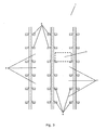
- Fig. 5 is a side view of the storage system 1 of Fig. 1 .
- part of a moving pattern 12 for the positioning/retrieval part 7 is illustrated.
- the illustrated moving ⁇ pattern 12 forms a meandering path which leads the positioning/retrieval part 7 past every second row of storage cells 2 in the matrix pattern.
- the cleaning unit is deigned in such a manner that it is capable of simultaneously performing cleaning operations on two storage cells 2, the moving pattern 12 illustrated in Fig. 5 could result in each of the storage cells 2 of the storage system 1 being cleaned.
- Fig. 6 is a view from above of the storage system of Fig. 2 and illustrating part of a moving pattern 13 for the positioning/retrieval part 7 in accordance with an embodiment of the invention.
- the moving pattern 13 leads the positioning/retrieval part 7 into each of the storage cells 2 which is passed by the positioning/retrieval part 7. Thereby cleaning operations are performed on the storage cells 2 while the positioning/retrieval part 7 has entered the storage cells 2.
Abstract
Description
- The present invention relates to an apparatus and a method for cleaning a storage system comprising a plurality of storage cells, in particular for cleaning a storage system in which the storage cells are arranged in a matrix pattern. The apparatus and method according to the invention are particularly suitable for cleaning a storage system for storing food products, e.g. meat.
- There is sometimes a need to store products in a storage system. This may, e.g., be in order to intermediately store products between various processing steps, and/or in order to store finished products before distributing them. A storage system for this use may advantageously comprise a plurality of storage cells which may be accessed individually. The storage cells may be arranged in a matrix pattern, e.g. in a large rack, or in a number of large racks, positioned side-by-side in a storage building or a warehouse.
- Such storage systems may be very large, i.e. they may comprise a vast number of storage cells. In order to be able to gain access to each of the storage cells for positioning a product in a storage cell or for retrieving a product, which has previously been positioned in a storage cell, in an easy manner, the storage system may be provided with a movable apparatus, e.g. in the form of a robot, which may be programmed to access a desired storage cell. Such a robot may advantageously be mounted in one or more rails on the floor, the rail(s) being arranged along a rack in such a manner that the robot may slide along the rack, i.e. in a substantially horizontal direction. The robot may further comprise a unit which is adapted to position products in the storage cells and to retrieve products from the storage cells. This unit is normally mounted on the robot in such a manner that it is movable in a substantially vertical direction. Thus, it is possible for the unit of the robot to access each of a plurality of storage cells positioned in a two-dimensional rack. The robot may be able to move the unit into a storage cell in order to position or retrieve an article. The robot may even be able to reach storage cells of two racks positioned adjacent and parallel to each other with an alley there between, the robot being mounted on a rail in the floor of the alley.
- Storage may take place using suitable containers, such as crates, which are positioned in the storage cells. This is, e.g., the case in the food industry and in the pharmaceutical industry. The products may be stored packed or unpacked and in open or closed containers, respectively.
- Due to hygiene requirements such storage systems must be cleaned and, in some cases, disinfected on a regular basis. This is of particular importance in the food industry. So far such cleaning has been performed manually. This is very cumbersome, time consuming and expensive. Furthermore, in order for the cleaning personnel to be able to reach each of the storage cells it is necessary to use ladders and/or movable platforms. The cleaning personnel will also have to bring various cleaning articles, such as spray lances, brushes, cleaning material, such as soap and/or disinfectant, etc. It may therefore be necessary to provide sufficient space between adjacent racks to allow cleaning personnel to climb or be lifted to each of the storage cells in a safe manner, while carrying the necessary articles along with them. Thereby less space will be available for storing products, and this is a further disadvantage.
-
EP 1 035 044 A2 - It is thus an object of the invention to provide an apparatus which allows for cleaning of a storage system comprising a plurality of storage cells while avoiding or considerably reducing the need for manual labour.
- It is a further object of the invention to provide a method for cleaning a storage system comprising a plurality of storage cells in such a manner that the need for manual labour is avoided or at least considerably reduced.
- It is an even further object of the invention to provide a storage system having a plurality of storage cells arranged in a matrix pattern, in which it is possible to store an increased number of articles, while allowing for sufficient cleaning of the storage system.
- According to a first aspect of the invention the above and other objects are fulfilled by providing an apparatus for positioning and retrieving articles in/from a storage system comprising a plurality of storage cells arranged in a matrix pattern, the apparatus comprising:
- a positioning/retrieval part adapted to position/retrieve an article in/from a selected storage cell,
- means for moving the positioning/retrieval part along at least two independent directions, the positioning/retrieval part thereby being capable of reaching each of the storage cells of the storage system in order to position/retrieve an article in/from a selected storage cell, and
- a cleaning unit comprising one or more cleaning parts, said cleaning unit being movable along with the positioning/retrieval part, the cleaning unit thereby being adapted to selectively perform cleaning operations at least at interior parts of each of the plurality of storage cells of the storage system.
- In the present context the term 'storage system' should preferably be interpreted as described above, i.e. as one or more racks comprising a plurality of storage cells. It could be a complete storage site, e.g. delimited by a storage building or a warehouse, or it may be part of a complete storage site, e.g. a single rack or a few racks of a storage site comprising a plurality of racks.
- The plurality of storage cells are arranged in a matrix pattern. This may be obtained by arranging the storage cells in a rack (forming a two-dimensional matrix pattern) or in a plurality of racks (forming a three-dimensional matrix pattern).
- The positioning/retrieval part is a part of the apparatus which is adapted to position or retrieve an article in/from a given storage cell when the positioning/retrieval part is positioned in or adjacent to that storage cell. The specific design of the positioning/retrieval part depends on the kind and shape of the articles being stored in the storage system, and on the design of the storage cells. Thus, the positioning/retrieval part may comprise gripping means for gripping an article while positioning it in or retrieving it from a storage cell. Alternatively or additionally, the positioning/retrieval part may comprise a platform which can support an article during positioning or retrieval. This is particularly suitable if the stored articles are carried in containers of uniform size and shape, and which can be supported in the storage cells by small carrying units, the carrying units being arranged in such a manner that the platform is allowed to enter beneath a storage cell. Such a platform may advantageously be operated as follows. When an article is to be positioned in a selected storage cell it is initially positioned on the platform. The platform is then moved to a position immediately adjacent to the selected storage cell in a manner which will be described further below. Then the platform is moved in a direction towards the selected storage cell at a level above a level defined by the carrying units. Subsequently, the platform is moved in a downwards direction until the article is supported by the carrying unit and is no longer supported by the platform. The platform is then retracted from the storage system. When an article is to be retrieved from a selected storage cell, the steps described above are performed in a reverse sequence.
- The means for moving the positioning/retrieval part may advantageously be a robot as described above. In this case the positioning/retrieval part is movable along a substantially horizontal direction, e.g. by means of a rail mounted on the floor or on the ceiling, and along a substantially vertical direction by means of a lift or crane arrangement. Thereby the positioning/retrieval part can be positioned adjacent to each of a plurality of storage cells arranged in a rack. It should be noted that the two directions do not need to be perpendicular to each other as long as they are independent, i.e. the two directions in combination define a plane spanned by vectors arranged along the directions. The positioning/retrieval part may further be movable along a third direction being at least substantially perpendicular to the directions defined above. In this case the positioning/retrieval part is further movable along a direction which is at least substantially normal to a plane spanned by vectors arranged along the two previously defined directions. This allows the positioning/retrieval part to enter a storage cell when the positioning/retrieval part has been positioned adjacent to that storage cell.
- The cleaning unit is adapted to perform various cleaning operations, i.e. it is capable of cleaning the storage system. This will be described in further details below. The cleaning unit is movable along with the positioning/retrieval unit. Since the positioning/retrieval unit, as explained above, is movable in such a manner that it can be positioned adjacent to and/or enter each of the storage cells, the cleaning unit can also be positioned adjacent to and/or enter each of the storage cells. Accordingly, the cleaning unit can perform cleaning operations in each of the storage cells. In particular, the cleaning unit can at least perform cleaning operations in interior parts of a selected storage cell, i.e. in parts where articles are actually stored, and where cleaning is therefore essential. It should, however, be understood that the cleaning unit may additionally be capable of performing cleaning operations on exterior parts of a selected storage cell. Thus, the storage cells can be individually cleaned, at least in interior parts, by means of the cleaning unit, i.e. with no or only little manual effort. Accordingly, the storage system can be cleaned in an automatic manner rather than in a manual manner, and the disadvantages described above are thereby avoided. In particular, the cleaning becomes more cost effective and less cumbersome, the necessary space between racks may even be reduced to only allow a robot to fit in, and the space available for storing articles may thereby be increased, thereby increasing the number of stored articles per unit area of the storage site. This is very advantageous.
- The cleaning unit may be mounted on or form part of the positioning/retrieval part. According to this embodiment the cleaning unit may form an integral part of the positioning/retrieval part, i.e. it may be manufactured along with the positioning/retrieval part. Alternatively, the cleaning unit may form a separate unit which can be mounted on the positioning/retrieval unit, either detachably or in a permanent manner. In the case that the cleaning unit is mounted on the positioning/retrieval unit in a detachable manner, the cleaning, unit may be mounted when it is desired to perform cleaning operations on the storage system, and when the cleaning operations have been completed, the cleaning unit may be detached, i.e. it will not be present on the positioning/retrieval part during normal operation of the apparatus.
- As an alternative, the cleaning unit may be a separate unit forming part of or being mounted on, permanently or detachably, another part of the apparatus. However, it should be noted that the cleaning unit should be movable along with the positioning/retrieval part, the cleaning unit thereby being capable of reaching each of the storage cells of the storage system.
- The cleaning part(s) may be selected from the group consisting of: fixed nozzles, movable nozzles, multi nozzle units, fixed brushes, movable brushes, dosing units, drying units, suction units, scrapers, and wiping units.
- It should be noted that cleaning parts from two or more of these groups may be selected.
- Nozzles may be for providing water and/or for providing waterborne or airborne cleaning material, such as soap, disinfectant, etc. The nozzles may be fixed, i.e. they may be mounted in such a manner that they spray in one direction only. Fixed nozzles may, e.g., provide a spraying pattern which forms a jet, a two-dimensional 'wall', has a conical shape, or any other suitable pattern. Fixed nozzles should be interpreted as nozzles which are fixed relatively to the cleaning unit, and it should be understood that such nozzles may be moved along with the cleaning unit.
- Alternatively, the nozzles may be movable, i.e. they may be mounted in such a manner that they are movable in order to form a desired spraying pattern, e.g. a conical pattern. Movable nozzles may be advantageous if it is desired to target surfaces which are not readily accessible from the cleaning unit. The movable nozzles may be rotatable and/or linearly movable.
- Nozzles may also be in the form of multi nozzle units. In this case a plurality of nozzles, fixed and/or movable, may be mounted on a nozzle head, thereby providing a desired spraying pattern.
- As an alternative to nozzles mounted on the cleaning unit, water and/or cleaning material may be provided by means of nozzles fixed on the storage system and/or directly on the building construction.
- Brushes may be used for scrubbing selected parts of the storage system, e.g. surfaces. The brushes may be fixed, i.e. fixed relatively to the cleaning unit, in which case the brushes are only movable along with the cleaning unit, in which case a scrubbing action is performed by moving the entire cleaning unit. Alternatively, the brushes may be movable, e.g. rotatable or linearly movable, in which case a scrubbing operation may be performed by moving the brushes relatively to the cleaning unit.
- Dosing units are units which are adapted to dose cleaning material, such as soap, disinfectant, etc., and/or water. The dosing units may be connected to or comprise nozzles as described above for delivering the dosed cleaning material or water. The dosing units are also preferably connected to a source. Thus, in the case that the dosing units are dosing a specific kind of cleaning material, they should be connected to a reservoir or container containing the relevant kind of cleaning materials. In the case that the dosing units are dosing water, they should be connected to a water supply, e.g. a tap.
- Drying units are units which are adapted to provide drying for the storage system when cleaning operations involving water have been performed. Drying units may advantageously comprise blowers supplying a stream of hot or cold air onto surfaces of the storage system. Such blowers may be fixed or movable as defined above.
- Suction units are units which are adapted to provide suction in order to suck up dirt, leftovers, etc. in the storage system. Thus, the suction units may function as a vacuum cleaner.
- Scrapers are parts which are adapted to scrape off leftovers or dirt which stick to surfaces of the storage system.
- Wiping units are units which may be used for wiping surfaces of the storage system. The wiping units may, e.g., be or comprise cloths, mops, etc.
- It should be noted that other cleaning parts than those mentioned above could be envisaged.
- The cleaning unit may be adapted to simultaneously perform cleaning operations on two or more storage cells. According to this embodiment, the cleaning unit may be designed in such a manner that, when positioned in an appropriate manner, it may enter two or more storage cells simultaneously. The storage cells may be positioned adjacent to each other, e.g. side-by-side or one above the other. Alternatively, they may be positioned in separate racks facing each other with an alley there between.
- The cleaning unit may be detachably mounted on the apparatus. As mentioned above, the cleaning unit may in this case be mounted on the apparatus during cleaning and detached during normal operation.
- The apparatus may advantageously be positioned in or form part of a storage system comprising a plurality of storage cells arranged in a matrix pattern, and the storage system may be adapted to store food products.
- According to a second aspect of the invention the above and other objects are fulfilled by providing a method of cleaning a storage system comprising a plurality of storage cells arranged in a matrix pattern, the method comprising the steps of:
- selecting a moving pattern for a cleaning unit,
- selecting a cleaning operation pattern for one or more cleaning parts of the cleaning unit, and
- moving and operating the cleaning unit in accordance with the selected moving pattern and the selected cleaning operation pattern, thereby obtaining a desired kind of cleaning in selected desired parts of the storage system.
- It should be noted that a skilled person would readily recognise that any feature described in combination with the first aspect of the invention may equally be combined with the second aspect of the invention, and vice versa.
- The method according to the second aspect of the invention may advantageously be performed using an apparatus according to the first aspect of the invention. The method according to the second aspect of the invention offers cleaning of the storage system in an automatic manner, and the advantages described above with reference to the first aspect of the invention are thereby obtained.
- The step of selecting a moving pattern may comprise selecting a velocity pattern for the cleaning unit. The velocity pattern may define a constant velocity by which the cleaning unit should be moved. Alternatively, it may define that the cleaning unit should be moved by varying velocities depending on the position along the movement path. Thus, the velocity pattern may define that the cleaning unit should be moved relatively slowly past a storage cell which is to be cleaned, while cleaning operations are performed, and that the cleaning unit should be moved somewhat faster when being moved from one storage cell to the next. The velocity pattern may even specify that the cleaning unit should be kept immovable while cleaning operations are performed on a storage cells which the cleaning unit is positioned adjacent to.
- Alternatively or additionally, the step of selecting a moving pattern may comprise selecting a pattern which leads the cleaning unit past a plurality of selected storage cells. At least some of the storage cells being passed in this manner are preferably cleaned. According to this embodiment, the moving pattern specifies directions of movement for the cleaning unit.
- Alternatively or additionally, the step of selecting a moving pattern may further comprise selecting a pattern in which the cleaning unit enters at least some of the selected storage cells. According to this embodiment, the moving pattern preferably specifies a path which moves the cleaning unit to a position adjacent to a selected storage cell. When the cleaning unit has been moved to such a position, it is moved in a perpendicular direction into the selected storage cell, and cleaning operations are then performed on that storage cells before the cleaning unit is retracted and moved to a position adjacent to the next storage cell.
- The selected storage cells may be positioned adjacent to each other in the matrix pattern. In this case the selected storage cells form a 'sub-matrix' of storage cells. Alternatively, the selected storage cells may be arranged in any other suitable manner. It may, thus, be desired to clean each storage cell in every second row, or every third storage cell in each row, or the storage cells may be selected in any other suitable manner.
- Thus, the selected storage cells may form a limited part of the storage system, such as a part known to be particularly dirty, or needing a special kind of cleaning.
- The step of selecting a cleaning operation may comprise selecting one or more cleaning sequences from a plurality of cleaning sequences. According to this embodiment, the cleaning operation may be composed by means of standard cleaning sequences, and a desired cleaning operation may be obtained by selecting one or more such standard cleaning sequences and putting them together in a desired order.
- The step of selecting a cleaning operation may comprise selecting one or more cleaning operations from the group consisting of: kind of applied cleaning material, amount of applied cleaning material, pattern of applied water, pressure of applied water, amount of applied water, temperature of applied water, drying, scrubbing pattern, scrubbing means, suction pattern, and suction means.
- As described above, applied cleaning materials may be soap, disinfectant, etc. A cleaning operation could be to select which kind of cleaning material should be applied at a specific point during the cleaning operation, and/or the amount of cleaning material supplied at a specific point during the cleaning operation.
- Other cleaning operations could relate to applied water, e.g. the pressure, amount, and/or temperature of water applied at a specific point during the cleaning operation. Alternatively or additionally, the pattern of the applied water could be specified, e.g. a jet, a two-dimensional 'wall', a conical pattern, a moving pattern, etc., as well as when water should be applied, and when no water should be applied.
- Drying may be provided by means of one or more blowers as described above, and this operation may specify when drying should be provided, in which direction, at which pressure and/or at which temperature the blower should provide drying.
- Scrubbing may specify when scrubbing should be applied, the kind of scrubbing means, such as fixed or moving brushes, wiping means, the scrubbing pattern, such as rotating, linearly moving, etc.
- Suction may specify the kind of suction means, e.g. a vacuum cleaner or the like and/or the suction force applied. The suction means may comprise a movable inlet, in which case a suction pattern may be defined.
- It should be noted that other kinds of cleaning operations than the ones mentioned above could be envisaged.
- The step of selecting a cleaning operation may comprise selecting a cleaning operation which provides cleaning of interior parts of at least one storage cell. As described above, such a cleaning operation makes it possible to clean the storage system, in particular the parts of the storage system where articles are stored, in an automatic manner.
- The step of moving may comprise moving the cleaning unit along with a positioning/retrieval part adapted to position/retrieve an article in/from a selected storage cell. In this case the cleaning unit may be mounted on or form part of the positioning/retrieval unit. This has already been described in details above.
- The step of moving may comprise moving the cleaning unit along a meandering path. In this case a large number of storage cells may be reached while the distance which the cleaning unit must travel is kept at a minimum. Alternatively, the cleaning unit may be moved along any other suitable path.
- The invention will now be described in details with reference to the accompanying drawings in which
-
Fig. 1 is a side view of a storage system comprising a plurality of storage cells arranged in a matrix pattern, and an apparatus for positioning and retrieving articles in/from the storage system, -
Fig. 2 is a view from above of the storage system ofFig. 1 , -
Fig. 3 is a side view of a part of the storage system ofFig. 1 , -
Fig. 4 is a side view of a positioning/retrieval part of an apparatus according to an embodiment of the invention, -
Fig. 5 is a side view of the storage system ofFig. 1 and illustrating part of a moving pattern in accordance with an embodiment of the invention, and -
Fig. 6 is a view from above of the storage system ofFig. 2 and illustrating part of a moving pattern in accordance with an embodiment of the invention. -
Fig. 1 is a side view of astorage system 1 comprising a plurality ofstorage cells 2 arranged in a matrix pattern. In thestorage system 1 ofFig. 1 , thestorage cells 2 are arranged in a large rack, and each of thestorage cells 2 is provided with acrate 3 for carrying an article being stored in the correspondingstorage cell 2. - The
storage system 1 is further provided with anapparatus 4 for positioning and retrieving articles in/from thestorage system 1. Theapparatus 4 is movable in a substantially horizontal direction along the rack by means ofrails 5. Thereby it is possible to position theapparatus 4 at a desired location along this direction. Theapparatus 4 is provided with lift means 6 adapted to move a positioning/retrieval part 7 along a substantially vertical direction. Thus, by moving theapparatus 4 along therails 5 and operating the lift means 6 in an appropriate manner, it is possible to position the positioning/retrieval part 7 adjacent to any of thestorage cells 2 of thestorage system 1. As described above, an article may thereby be positioned in or retrieved from thatstorage cell 2. -
Fig. 2 is a view from above of thestorage system 1 ofFig. 1 , illustrating that thestorage system 1 comprises six racks identical to the rack shown inFig. 1 . Furthermore, the storage system is provided with threeapparatuses 4, eachapparatus 4 being capable of gaining access tostorage cells 2 positioned in two adjacent racks. -
Fig. 3 is a side view of a part of thestorage system 1 ofFig. 1 . In the part of thestorage system 1 shown inFig. 3 thecrates 3 have been removed. However, the position of thecrates 3 in thestorage cells 2 during normal operation of thestorage system 1 is illustrated by a dotted line. Eachstorage cell 2 is provided with a set of supportingsurfaces 8 adapted to support and hold acrate 3 as illustrated by the dotted line. This has been described in detail above. It should be noted that when thestorage system 1 is being cleaned, there is preferably nocrates 3 present in thestorage system 1, or at least in the part being cleaned. Thereby it is possible to gain access to all the surfaces of the storage system, in particular in each of thestorage cells 2, in such a manner that sufficient and appropriate cleaning can be provided. -
Fig. 4 is a side view of a positioning/retrieval part 7 of an apparatus according to an embodiment of the invention. A nozzle arrangement 9 comprising twonozzles 10 is mounted on the positioning/retrieval part 7. Water and/or one or more relevant cleaning materials can be delivered via the nozzle arrangement 9, thereby providing water and/or cleaning material to a part of the storage system where the positioning/retrieval part 7 is positioned. - The positioning/
retrieval part 7 is further provided with tworotating brushes 11 which may be used for scrubbing a part of the storage system where the positioning/retrieval part 7 is positioned. - The nozzle arrangement 9 and the rotating
brushes 11 in combination form a cleaning unit mounted on the positioning/retrieval part 7, and thereby being movable along with it. Thus, if the positioning/retrieval part 7 is moved to a position adjacent to a selected storage cell as described above with reference toFig. 1 , the nozzle arrangement 9 and thebrushes 11 can perform cleaning operations on that storage cell. This may advantageously be done by spraying water and/or one or more relevant cleaning materials onto surfaces of the selected storage cell by means of the nozzle arrangement 9, and subsequently scrubbing the surfaces by means of the rotating brushes 11. At least part of this cleaning operation may be performed while the cleaning unit, and optionally the entire positioning/retrieval part 7, has entered the storage cell. -
Fig. 5 is a side view of thestorage system 1 ofFig. 1 . InFig. 5 part of a movingpattern 12 for the positioning/retrieval part 7 is illustrated. The illustrated moving·pattern 12 forms a meandering path which leads the positioning/retrieval part 7 past every second row ofstorage cells 2 in the matrix pattern. In the case that the cleaning unit is deigned in such a manner that it is capable of simultaneously performing cleaning operations on twostorage cells 2, the movingpattern 12 illustrated inFig. 5 could result in each of thestorage cells 2 of thestorage system 1 being cleaned. -
Fig. 6 is a view from above of the storage system ofFig. 2 and illustrating part of a movingpattern 13 for the positioning/retrieval part 7 in accordance with an embodiment of the invention. The movingpattern 13 leads the positioning/retrieval part 7 into each of thestorage cells 2 which is passed by the positioning/retrieval part 7. Thereby cleaning operations are performed on thestorage cells 2 while the positioning/retrieval part 7 has entered thestorage cells 2. - As mentioned above, it should be noted that during cleaning the
crates 3 will normally not be present in thestorage system 1. However, for the sake of clarity they are shown inFigs. 5 and6 .
Claims (18)
- An apparatus (4) for positioning and retrieving articles in/from a storage system (1) comprising a plurality of storage cells (2) arranged in a matrix pattern, the apparatus (4) comprising:- a positioning/retrieval part (7) adapted to position/retrieve an article in/from a selected storage cell (2),- means (6) for moving the positioning/retrieval part (7) along at least two independent directions, the positioning/retrieval part (7) thereby being capable of reaching each of the storage cells (2) of the storage system (1) in order to position/retrieve an article in/from a selected storage cell (2), and- a cleaning unit (9, 10, 11) comprising one or more cleaning parts, said cleaning unit (9, 10, 11) being movable along with the positioning/retrieval part (7),characterized in that the cleaning unit (9, 10, 11) is thereby adapted to selectively perform cleaning operations at least at interior parts of each of the plurality of storage cells (2) of the storage system (1).
- An apparatus (4) according to claim 1, wherein the cleaning unit (9, 10, 11) is mounted on or forms part of the positioning/retrieval part (7).
- An apparatus (4) according to claim 1 or 2, wherein the cleaning part(s) is/are selected from the group consisting of: fixed nozzles, movable nozzles, multi nozzle units, fixed brushes, movable brushes, dosing units, drying units, suction units, scrapers and wiping units.
- An apparatus (4) according to any of the preceding claims, wherein the cleaning unit (9, 10, 11) is adapted to simultaneously perform cleaning operations on two or more storage cells (2).
- An apparatus (4) according to any of the preceding claims, wherein the cleaning unit (9, 10, 11) is detachably mounted on the apparatus (4).
- A storage system (1) comprising a plurality of storage cells (2) arranged in a matrix pattern and an apparatus (4) according to any of the preceding claims.
- A storage system (1) according to claim 6, said storage system (1) being adapted to store food products.
- A method of cleaning a storage system (1) comprising a plurality of storage cells (2) arranged in a matrix pattern,
characterized in that the method comprises the steps of:- selecting a moving pattern for a cleaning unit (9, 10, 11),- selecting a cleaning operation pattern for one or more cleaning parts of the cleaning unit (9, 10, 11), and- moving and operating the cleaning unit (9, 10, 11) in accordance with the selected moving pattern and the selected cleaning operation pattern, thereby obtaining a desired kind of cleaning in selected desired parts of the storage system (1). - A method according to claim 8, wherein the step of selecting a moving pattern comprises selecting a velocity pattern for the cleaning unit (9, 10, 11).
- A method according to claim 8 or 9, wherein the step of selecting a moving pattern comprises selecting a pattern which leads the cleaning unit (9, 10, 11) past a plurality of selected storage cells (2).
- A method according to claim 10, wherein the step of selecting a moving pattern further comprises selecting a pattern in which the cleaning unit (9, 10, 11) enters at least some of the selected storage cells (2).
- A method according to claim 10 or 11, wherein the selected storage cells (2) are positioned adjacent to each other in the matrix pattern.
- A method according to any of claims 10-12, wherein the selected storage cells (2) form a limited part of the storage system (1).
- A method according to any of claims 8-13, wherein the step of selecting a cleaning operation comprises selecting one or more cleaning sequences from a plurality of cleaning sequences.
- A method according to any of claims 8-14, wherein the step of selecting a cleaning operation comprises selecting one or more cleaning operations from the group consisting of: kind of applied cleaning material, amount of applied cleaning material, pattern of applied water, pressure of applied water, amount of applied water, temperature of applied water, drying, scrubbing pattern, scrubbing means, suction pattern, and suction means.
- A method according to any of claims 8-14, wherein the step of selecting a cleaning operation comprises selecting a cleaning operation which provides cleaning of interior parts of at least one storage cell (2).
- A method according to any of claims 8-16, wherein the step of moving comprises moving the cleaning unit (9, 10, 11) along with a positioning/retrieval part (7) adapted to position/retrieve an article in/from a selected storage cell (2).
- A method according to any of claims 8-17, wherein the step of moving comprises moving the cleaning unit (9, 10, 11) along a meandering path.
Priority Applications (2)
| Application Number | Priority Date | Filing Date | Title |
|---|---|---|---|
| EP07822695A EP2091670B1 (en) | 2006-11-22 | 2007-11-19 | An apparatus and a method for cleaning a storage system |
| PL07822695T PL2091670T3 (en) | 2006-11-22 | 2007-11-19 | An apparatus and a method for cleaning a storage system |
Applications Claiming Priority (3)
| Application Number | Priority Date | Filing Date | Title |
|---|---|---|---|
| EP06024191 | 2006-11-22 | ||
| EP07822695A EP2091670B1 (en) | 2006-11-22 | 2007-11-19 | An apparatus and a method for cleaning a storage system |
| PCT/EP2007/062487 WO2008061951A1 (en) | 2006-11-22 | 2007-11-19 | An apparatus and a method for cleaning a storage system |
Publications (2)
| Publication Number | Publication Date |
|---|---|
| EP2091670A1 EP2091670A1 (en) | 2009-08-26 |
| EP2091670B1 true EP2091670B1 (en) | 2012-01-25 |
Family
ID=37943914
Family Applications (1)
| Application Number | Title | Priority Date | Filing Date |
|---|---|---|---|
| EP07822695A Active EP2091670B1 (en) | 2006-11-22 | 2007-11-19 | An apparatus and a method for cleaning a storage system |
Country Status (5)
| Country | Link |
|---|---|
| EP (1) | EP2091670B1 (en) |
| AT (1) | ATE542612T1 (en) |
| DK (1) | DK2091670T3 (en) |
| PL (1) | PL2091670T3 (en) |
| WO (1) | WO2008061951A1 (en) |
Cited By (1)
| Publication number | Priority date | Publication date | Assignee | Title |
|---|---|---|---|---|
| US10654661B2 (en) | 2016-02-01 | 2020-05-19 | Autostore Technology AS | Cleaning bin for cleaning a storage grid of a storage system |
Families Citing this family (8)
| Publication number | Priority date | Publication date | Assignee | Title |
|---|---|---|---|---|
| DE102008027376B4 (en) * | 2008-06-09 | 2017-02-02 | Kht Kommissionier- Und Handhabungstechnik Gmbh | Device for storing and retrieving goods, in particular pharmaceutical packaging and method for operating such a device |
| DE102009009244A1 (en) | 2009-02-17 | 2010-08-26 | Jürgen Löhrke GmbH | Cleaning system and cleaning process |
| DE202013004016U1 (en) * | 2013-04-30 | 2014-08-01 | Michael Körbitz | Cleaning device for high shelves intended for storing containments |
| US11858738B2 (en) | 2013-08-09 | 2024-01-02 | Ocado Innovation Limited | Apparatus for retrieving units from a storage system |
| GB201404870D0 (en) * | 2014-03-18 | 2014-04-30 | Ocado Ltd | Robotic service device and handling method |
| DE202014004665U1 (en) | 2014-06-04 | 2014-06-25 | Labetherm Limited Zweigniederlassung Deutschland | Device for cleaning rolls and shelves of the picking warehouse |
| DE102014008188A1 (en) | 2014-06-04 | 2015-12-31 | Labetherm Limited Zweigniederlassung Deutschland | Device for cleaning rolls and shelf surfaces of the picking warehouse |
| EP3501673B1 (en) * | 2017-12-22 | 2022-02-09 | Borbet Thüringen GmbH | Cleaning machine and method for its operation |
Family Cites Families (3)
| Publication number | Priority date | Publication date | Assignee | Title |
|---|---|---|---|---|
| FR2403969A1 (en) * | 1977-09-26 | 1979-04-20 | Franche Comte Union Coop Fruit | Rotating palette for lifting truck - for manipulating, turning over and transporting round cheeses |
| DE3222977A1 (en) * | 1982-06-17 | 1983-12-22 | Schweizerische Aluminium AG, 3965 Chippis | Industrial truck, in particular for a foundry |
| DE19910933B4 (en) | 1999-03-12 | 2004-07-08 | Leuze Electronic Gmbh + Co Kg | Device for positioning a vehicle |
-
2007
- 2007-11-19 PL PL07822695T patent/PL2091670T3/en unknown
- 2007-11-19 EP EP07822695A patent/EP2091670B1/en active Active
- 2007-11-19 DK DK07822695.8T patent/DK2091670T3/en active
- 2007-11-19 WO PCT/EP2007/062487 patent/WO2008061951A1/en active Application Filing
- 2007-11-19 AT AT07822695T patent/ATE542612T1/en active
Cited By (2)
| Publication number | Priority date | Publication date | Assignee | Title |
|---|---|---|---|---|
| US10654661B2 (en) | 2016-02-01 | 2020-05-19 | Autostore Technology AS | Cleaning bin for cleaning a storage grid of a storage system |
| US11104522B2 (en) | 2016-02-01 | 2021-08-31 | Autostore Technology AS | Cleaning bin for cleaning a storage grid of a storage system |
Also Published As
| Publication number | Publication date |
|---|---|
| WO2008061951A1 (en) | 2008-05-29 |
| PL2091670T3 (en) | 2012-08-31 |
| EP2091670A1 (en) | 2009-08-26 |
| ATE542612T1 (en) | 2012-02-15 |
| DK2091670T3 (en) | 2012-05-14 |
Similar Documents
| Publication | Publication Date | Title |
|---|---|---|
| EP2091670B1 (en) | An apparatus and a method for cleaning a storage system | |
| US4561144A (en) | Machine for washing flat tableware | |
| EP2932879A1 (en) | Washing machine with a low number of nozzles | |
| US7114462B2 (en) | Automated cage cleaning apparatus and method | |
| US7363104B2 (en) | Product storage and picking system and method of storing and picking products | |
| DK2609021T3 (en) | Storage shelf system for storage of storage material | |
| US5364220A (en) | Shelf servicing apparatus | |
| CN109420635B (en) | Cleaning device and method for cleaning a conveyor screw | |
| US10364098B2 (en) | Robotic picking system device and method | |
| JP6151741B2 (en) | Livestock cleaning and disinfection system | |
| US10357808B2 (en) | Methods and systems for use in washing bulk containers | |
| EP2393734A1 (en) | Storage and order collection system | |
| JP2014528036A (en) | High density storage equipment | |
| JP5065375B2 (en) | Apparatus and method for cleaning the floor of an animal containment facility | |
| US4408625A (en) | Article washing means with movable spray heads | |
| US4004701A (en) | Handling and dispensing system and apparatus for cylindrical objects | |
| WO2000018522A1 (en) | Vertical crate washing and drying device and methods | |
| US11090701B2 (en) | Bin cleaning systems and methods of use | |
| KR102055732B1 (en) | Automatic cup wash system for drinking fountains | |
| EP0956766B1 (en) | Method and apparatus for unloading crates from a container onto a transfer conveyor | |
| EP4021213A1 (en) | Food product printer | |
| JP5202201B2 (en) | Dishwasher | |
| JP2681411B2 (en) | Automatic sprayer for chemical solution for plant test cultivation | |
| FR2549364A1 (en) | Method and device for washing articles of flat crockery, such as dishes, trays and plates | |
| JP7036847B2 (en) | Dishwashing aid |
Legal Events
| Date | Code | Title | Description |
|---|---|---|---|
| PUAI | Public reference made under article 153(3) epc to a published international application that has entered the european phase |
Free format text: ORIGINAL CODE: 0009012 |
|
| 17P | Request for examination filed |
Effective date: 20090622 |
|
| AK | Designated contracting states |
Kind code of ref document: A1 Designated state(s): AT BE BG CH CY CZ DE DK EE ES FI FR GB GR HU IE IS IT LI LT LU LV MC MT NL PL PT RO SE SI SK TR |
|
| DAX | Request for extension of the european patent (deleted) | ||
| 17Q | First examination report despatched |
Effective date: 20101210 |
|
| GRAP | Despatch of communication of intention to grant a patent |
Free format text: ORIGINAL CODE: EPIDOSNIGR1 |
|
| GRAS | Grant fee paid |
Free format text: ORIGINAL CODE: EPIDOSNIGR3 |
|
| GRAA | (expected) grant |
Free format text: ORIGINAL CODE: 0009210 |
|
| AK | Designated contracting states |
Kind code of ref document: B1 Designated state(s): AT BE BG CH CY CZ DE DK EE ES FI FR GB GR HU IE IS IT LI LT LU LV MC MT NL PL PT RO SE SI SK TR |
|
| REG | Reference to a national code |
Ref country code: GB Ref legal event code: FG4D |
|
| REG | Reference to a national code |
Ref country code: CH Ref legal event code: EP |
|
| REG | Reference to a national code |
Ref country code: AT Ref legal event code: REF Ref document number: 542612 Country of ref document: AT Kind code of ref document: T Effective date: 20120215 |
|
| REG | Reference to a national code |
Ref country code: IE Ref legal event code: FG4D |
|
| REG | Reference to a national code |
Ref country code: DE Ref legal event code: R096 Ref document number: 602007020322 Country of ref document: DE Effective date: 20120322 |
|
| REG | Reference to a national code |
Ref country code: DK Ref legal event code: T3 |
|
| REG | Reference to a national code |
Ref country code: NL Ref legal event code: VDEP Effective date: 20120125 |
|
| LTIE | Lt: invalidation of european patent or patent extension |
Effective date: 20120125 |
|
| PG25 | Lapsed in a contracting state [announced via postgrant information from national office to epo] |
Ref country code: BE Free format text: LAPSE BECAUSE OF FAILURE TO SUBMIT A TRANSLATION OF THE DESCRIPTION OR TO PAY THE FEE WITHIN THE PRESCRIBED TIME-LIMIT Effective date: 20120125 Ref country code: BG Free format text: LAPSE BECAUSE OF FAILURE TO SUBMIT A TRANSLATION OF THE DESCRIPTION OR TO PAY THE FEE WITHIN THE PRESCRIBED TIME-LIMIT Effective date: 20120425 Ref country code: NL Free format text: LAPSE BECAUSE OF FAILURE TO SUBMIT A TRANSLATION OF THE DESCRIPTION OR TO PAY THE FEE WITHIN THE PRESCRIBED TIME-LIMIT Effective date: 20120125 Ref country code: LT Free format text: LAPSE BECAUSE OF FAILURE TO SUBMIT A TRANSLATION OF THE DESCRIPTION OR TO PAY THE FEE WITHIN THE PRESCRIBED TIME-LIMIT Effective date: 20120125 Ref country code: IS Free format text: LAPSE BECAUSE OF FAILURE TO SUBMIT A TRANSLATION OF THE DESCRIPTION OR TO PAY THE FEE WITHIN THE PRESCRIBED TIME-LIMIT Effective date: 20120525 |
|
| PG25 | Lapsed in a contracting state [announced via postgrant information from national office to epo] |
Ref country code: PT Free format text: LAPSE BECAUSE OF FAILURE TO SUBMIT A TRANSLATION OF THE DESCRIPTION OR TO PAY THE FEE WITHIN THE PRESCRIBED TIME-LIMIT Effective date: 20120525 Ref country code: FI Free format text: LAPSE BECAUSE OF FAILURE TO SUBMIT A TRANSLATION OF THE DESCRIPTION OR TO PAY THE FEE WITHIN THE PRESCRIBED TIME-LIMIT Effective date: 20120125 Ref country code: GR Free format text: LAPSE BECAUSE OF FAILURE TO SUBMIT A TRANSLATION OF THE DESCRIPTION OR TO PAY THE FEE WITHIN THE PRESCRIBED TIME-LIMIT Effective date: 20120426 Ref country code: LV Free format text: LAPSE BECAUSE OF FAILURE TO SUBMIT A TRANSLATION OF THE DESCRIPTION OR TO PAY THE FEE WITHIN THE PRESCRIBED TIME-LIMIT Effective date: 20120125 |
|
| REG | Reference to a national code |
Ref country code: PL Ref legal event code: T3 |
|
| REG | Reference to a national code |
Ref country code: AT Ref legal event code: MK05 Ref document number: 542612 Country of ref document: AT Kind code of ref document: T Effective date: 20120125 |
|
| PG25 | Lapsed in a contracting state [announced via postgrant information from national office to epo] |
Ref country code: CY Free format text: LAPSE BECAUSE OF FAILURE TO SUBMIT A TRANSLATION OF THE DESCRIPTION OR TO PAY THE FEE WITHIN THE PRESCRIBED TIME-LIMIT Effective date: 20120125 |
|
| PG25 | Lapsed in a contracting state [announced via postgrant information from national office to epo] |
Ref country code: CZ Free format text: LAPSE BECAUSE OF FAILURE TO SUBMIT A TRANSLATION OF THE DESCRIPTION OR TO PAY THE FEE WITHIN THE PRESCRIBED TIME-LIMIT Effective date: 20120125 Ref country code: RO Free format text: LAPSE BECAUSE OF FAILURE TO SUBMIT A TRANSLATION OF THE DESCRIPTION OR TO PAY THE FEE WITHIN THE PRESCRIBED TIME-LIMIT Effective date: 20120125 Ref country code: EE Free format text: LAPSE BECAUSE OF FAILURE TO SUBMIT A TRANSLATION OF THE DESCRIPTION OR TO PAY THE FEE WITHIN THE PRESCRIBED TIME-LIMIT Effective date: 20120125 Ref country code: SE Free format text: LAPSE BECAUSE OF FAILURE TO SUBMIT A TRANSLATION OF THE DESCRIPTION OR TO PAY THE FEE WITHIN THE PRESCRIBED TIME-LIMIT Effective date: 20120125 Ref country code: SI Free format text: LAPSE BECAUSE OF FAILURE TO SUBMIT A TRANSLATION OF THE DESCRIPTION OR TO PAY THE FEE WITHIN THE PRESCRIBED TIME-LIMIT Effective date: 20120125 |
|
| PG25 | Lapsed in a contracting state [announced via postgrant information from national office to epo] |
Ref country code: IT Free format text: LAPSE BECAUSE OF FAILURE TO SUBMIT A TRANSLATION OF THE DESCRIPTION OR TO PAY THE FEE WITHIN THE PRESCRIBED TIME-LIMIT Effective date: 20120125 Ref country code: SK Free format text: LAPSE BECAUSE OF FAILURE TO SUBMIT A TRANSLATION OF THE DESCRIPTION OR TO PAY THE FEE WITHIN THE PRESCRIBED TIME-LIMIT Effective date: 20120125 |
|
| PLBE | No opposition filed within time limit |
Free format text: ORIGINAL CODE: 0009261 |
|
| STAA | Information on the status of an ep patent application or granted ep patent |
Free format text: STATUS: NO OPPOSITION FILED WITHIN TIME LIMIT |
|
| 26N | No opposition filed |
Effective date: 20121026 |
|
| PG25 | Lapsed in a contracting state [announced via postgrant information from national office to epo] |
Ref country code: AT Free format text: LAPSE BECAUSE OF FAILURE TO SUBMIT A TRANSLATION OF THE DESCRIPTION OR TO PAY THE FEE WITHIN THE PRESCRIBED TIME-LIMIT Effective date: 20120125 |
|
| REG | Reference to a national code |
Ref country code: DE Ref legal event code: R097 Ref document number: 602007020322 Country of ref document: DE Effective date: 20121026 |
|
| PG25 | Lapsed in a contracting state [announced via postgrant information from national office to epo] |
Ref country code: ES Free format text: LAPSE BECAUSE OF FAILURE TO SUBMIT A TRANSLATION OF THE DESCRIPTION OR TO PAY THE FEE WITHIN THE PRESCRIBED TIME-LIMIT Effective date: 20120506 |
|
| REG | Reference to a national code |
Ref country code: CH Ref legal event code: PL |
|
| PG25 | Lapsed in a contracting state [announced via postgrant information from national office to epo] |
Ref country code: LI Free format text: LAPSE BECAUSE OF NON-PAYMENT OF DUE FEES Effective date: 20121130 Ref country code: CH Free format text: LAPSE BECAUSE OF NON-PAYMENT OF DUE FEES Effective date: 20121130 |
|
| REG | Reference to a national code |
Ref country code: IE Ref legal event code: MM4A |
|
| PG25 | Lapsed in a contracting state [announced via postgrant information from national office to epo] |
Ref country code: IE Free format text: LAPSE BECAUSE OF NON-PAYMENT OF DUE FEES Effective date: 20121119 |
|
| PG25 | Lapsed in a contracting state [announced via postgrant information from national office to epo] |
Ref country code: MT Free format text: LAPSE BECAUSE OF FAILURE TO SUBMIT A TRANSLATION OF THE DESCRIPTION OR TO PAY THE FEE WITHIN THE PRESCRIBED TIME-LIMIT Effective date: 20120125 |
|
| PG25 | Lapsed in a contracting state [announced via postgrant information from national office to epo] |
Ref country code: MC Free format text: LAPSE BECAUSE OF NON-PAYMENT OF DUE FEES Effective date: 20121130 Ref country code: TR Free format text: LAPSE BECAUSE OF FAILURE TO SUBMIT A TRANSLATION OF THE DESCRIPTION OR TO PAY THE FEE WITHIN THE PRESCRIBED TIME-LIMIT Effective date: 20120125 |
|
| PG25 | Lapsed in a contracting state [announced via postgrant information from national office to epo] |
Ref country code: LU Free format text: LAPSE BECAUSE OF NON-PAYMENT OF DUE FEES Effective date: 20121119 |
|
| REG | Reference to a national code |
Ref country code: GB Ref legal event code: 732E Free format text: REGISTERED BETWEEN 20140515 AND 20140521 |
|
| REG | Reference to a national code |
Ref country code: DE Ref legal event code: R081 Ref document number: 602007020322 Country of ref document: DE Owner name: HUMBOLDT B.V., NL Free format text: FORMER OWNER: KJ INDUSTRIES A/S, ESBJERG, DK Effective date: 20140519 |
|
| REG | Reference to a national code |
Ref country code: FR Ref legal event code: TP Owner name: HUMBOLDT B.V., NL Effective date: 20140604 |
|
| PG25 | Lapsed in a contracting state [announced via postgrant information from national office to epo] |
Ref country code: HU Free format text: LAPSE BECAUSE OF FAILURE TO SUBMIT A TRANSLATION OF THE DESCRIPTION OR TO PAY THE FEE WITHIN THE PRESCRIBED TIME-LIMIT Effective date: 20071119 |
|
| REG | Reference to a national code |
Ref country code: FR Ref legal event code: PLFP Year of fee payment: 9 |
|
| REG | Reference to a national code |
Ref country code: FR Ref legal event code: PLFP Year of fee payment: 10 |
|
| REG | Reference to a national code |
Ref country code: FR Ref legal event code: PLFP Year of fee payment: 11 |
|
| PGFP | Annual fee paid to national office [announced via postgrant information from national office to epo] |
Ref country code: PL Payment date: 20221025 Year of fee payment: 16 |
|
| P01 | Opt-out of the competence of the unified patent court (upc) registered |
Effective date: 20230514 |
|
| PGFP | Annual fee paid to national office [announced via postgrant information from national office to epo] |
Ref country code: GB Payment date: 20231019 Year of fee payment: 17 |
|
| PGFP | Annual fee paid to national office [announced via postgrant information from national office to epo] |
Ref country code: FR Payment date: 20231019 Year of fee payment: 17 Ref country code: DK Payment date: 20231019 Year of fee payment: 17 Ref country code: DE Payment date: 20231019 Year of fee payment: 17 |
|
| PGFP | Annual fee paid to national office [announced via postgrant information from national office to epo] |
Ref country code: PL Payment date: 20231025 Year of fee payment: 17 |