EP2090851A1 - Échangeur de chaleur doté d'une chambre de mélange - Google Patents
Échangeur de chaleur doté d'une chambre de mélange Download PDFInfo
- Publication number
- EP2090851A1 EP2090851A1 EP08151505A EP08151505A EP2090851A1 EP 2090851 A1 EP2090851 A1 EP 2090851A1 EP 08151505 A EP08151505 A EP 08151505A EP 08151505 A EP08151505 A EP 08151505A EP 2090851 A1 EP2090851 A1 EP 2090851A1
- Authority
- EP
- European Patent Office
- Prior art keywords
- heat exchanger
- distribution
- cover plate
- plate
- manifold
- Prior art date
- Legal status (The legal status is an assumption and is not a legal conclusion. Google has not performed a legal analysis and makes no representation as to the accuracy of the status listed.)
- Withdrawn
Links
Images


Classifications
-
- F—MECHANICAL ENGINEERING; LIGHTING; HEATING; WEAPONS; BLASTING
- F28—HEAT EXCHANGE IN GENERAL
- F28D—HEAT-EXCHANGE APPARATUS, NOT PROVIDED FOR IN ANOTHER SUBCLASS, IN WHICH THE HEAT-EXCHANGE MEDIA DO NOT COME INTO DIRECT CONTACT
- F28D1/00—Heat-exchange apparatus having stationary conduit assemblies for one heat-exchange medium only, the media being in contact with different sides of the conduit wall, in which the other heat-exchange medium is a large body of fluid, e.g. domestic or motor car radiators
- F28D1/02—Heat-exchange apparatus having stationary conduit assemblies for one heat-exchange medium only, the media being in contact with different sides of the conduit wall, in which the other heat-exchange medium is a large body of fluid, e.g. domestic or motor car radiators with heat-exchange conduits immersed in the body of fluid
- F28D1/04—Heat-exchange apparatus having stationary conduit assemblies for one heat-exchange medium only, the media being in contact with different sides of the conduit wall, in which the other heat-exchange medium is a large body of fluid, e.g. domestic or motor car radiators with heat-exchange conduits immersed in the body of fluid with tubular conduits
- F28D1/053—Heat-exchange apparatus having stationary conduit assemblies for one heat-exchange medium only, the media being in contact with different sides of the conduit wall, in which the other heat-exchange medium is a large body of fluid, e.g. domestic or motor car radiators with heat-exchange conduits immersed in the body of fluid with tubular conduits the conduits being straight
- F28D1/0535—Heat-exchange apparatus having stationary conduit assemblies for one heat-exchange medium only, the media being in contact with different sides of the conduit wall, in which the other heat-exchange medium is a large body of fluid, e.g. domestic or motor car radiators with heat-exchange conduits immersed in the body of fluid with tubular conduits the conduits being straight the conduits having a non-circular cross-section
- F28D1/05366—Assemblies of conduits connected to common headers, e.g. core type radiators
- F28D1/05391—Assemblies of conduits connected to common headers, e.g. core type radiators with multiple rows of conduits or with multi-channel conduits combined with a particular flow pattern, e.g. multi-row multi-stage radiators
-
- F—MECHANICAL ENGINEERING; LIGHTING; HEATING; WEAPONS; BLASTING
- F25—REFRIGERATION OR COOLING; COMBINED HEATING AND REFRIGERATION SYSTEMS; HEAT PUMP SYSTEMS; MANUFACTURE OR STORAGE OF ICE; LIQUEFACTION SOLIDIFICATION OF GASES
- F25B—REFRIGERATION MACHINES, PLANTS OR SYSTEMS; COMBINED HEATING AND REFRIGERATION SYSTEMS; HEAT PUMP SYSTEMS
- F25B39/00—Evaporators; Condensers
- F25B39/02—Evaporators
- F25B39/028—Evaporators having distributing means
-
- F—MECHANICAL ENGINEERING; LIGHTING; HEATING; WEAPONS; BLASTING
- F25—REFRIGERATION OR COOLING; COMBINED HEATING AND REFRIGERATION SYSTEMS; HEAT PUMP SYSTEMS; MANUFACTURE OR STORAGE OF ICE; LIQUEFACTION SOLIDIFICATION OF GASES
- F25B—REFRIGERATION MACHINES, PLANTS OR SYSTEMS; COMBINED HEATING AND REFRIGERATION SYSTEMS; HEAT PUMP SYSTEMS
- F25B41/00—Fluid-circulation arrangements
-
- F—MECHANICAL ENGINEERING; LIGHTING; HEATING; WEAPONS; BLASTING
- F28—HEAT EXCHANGE IN GENERAL
- F28D—HEAT-EXCHANGE APPARATUS, NOT PROVIDED FOR IN ANOTHER SUBCLASS, IN WHICH THE HEAT-EXCHANGE MEDIA DO NOT COME INTO DIRECT CONTACT
- F28D1/00—Heat-exchange apparatus having stationary conduit assemblies for one heat-exchange medium only, the media being in contact with different sides of the conduit wall, in which the other heat-exchange medium is a large body of fluid, e.g. domestic or motor car radiators
- F28D1/02—Heat-exchange apparatus having stationary conduit assemblies for one heat-exchange medium only, the media being in contact with different sides of the conduit wall, in which the other heat-exchange medium is a large body of fluid, e.g. domestic or motor car radiators with heat-exchange conduits immersed in the body of fluid
- F28D1/04—Heat-exchange apparatus having stationary conduit assemblies for one heat-exchange medium only, the media being in contact with different sides of the conduit wall, in which the other heat-exchange medium is a large body of fluid, e.g. domestic or motor car radiators with heat-exchange conduits immersed in the body of fluid with tubular conduits
- F28D1/047—Heat-exchange apparatus having stationary conduit assemblies for one heat-exchange medium only, the media being in contact with different sides of the conduit wall, in which the other heat-exchange medium is a large body of fluid, e.g. domestic or motor car radiators with heat-exchange conduits immersed in the body of fluid with tubular conduits the conduits being bent, e.g. in a serpentine or zig-zag
- F28D1/0475—Heat-exchange apparatus having stationary conduit assemblies for one heat-exchange medium only, the media being in contact with different sides of the conduit wall, in which the other heat-exchange medium is a large body of fluid, e.g. domestic or motor car radiators with heat-exchange conduits immersed in the body of fluid with tubular conduits the conduits being bent, e.g. in a serpentine or zig-zag the conduits having a single U-bend
- F28D1/0476—Heat-exchange apparatus having stationary conduit assemblies for one heat-exchange medium only, the media being in contact with different sides of the conduit wall, in which the other heat-exchange medium is a large body of fluid, e.g. domestic or motor car radiators with heat-exchange conduits immersed in the body of fluid with tubular conduits the conduits being bent, e.g. in a serpentine or zig-zag the conduits having a single U-bend the conduits having a non-circular cross-section
-
- F—MECHANICAL ENGINEERING; LIGHTING; HEATING; WEAPONS; BLASTING
- F28—HEAT EXCHANGE IN GENERAL
- F28F—DETAILS OF HEAT-EXCHANGE AND HEAT-TRANSFER APPARATUS, OF GENERAL APPLICATION
- F28F9/00—Casings; Header boxes; Auxiliary supports for elements; Auxiliary members within casings
- F28F9/02—Header boxes; End plates
- F28F9/026—Header boxes; End plates with static flow control means, e.g. with means for uniformly distributing heat exchange media into conduits
- F28F9/0278—Header boxes; End plates with static flow control means, e.g. with means for uniformly distributing heat exchange media into conduits in the form of stacked distribution plates or perforated plates arranged over end plates
-
- Y—GENERAL TAGGING OF NEW TECHNOLOGICAL DEVELOPMENTS; GENERAL TAGGING OF CROSS-SECTIONAL TECHNOLOGIES SPANNING OVER SEVERAL SECTIONS OF THE IPC; TECHNICAL SUBJECTS COVERED BY FORMER USPC CROSS-REFERENCE ART COLLECTIONS [XRACs] AND DIGESTS
- Y10—TECHNICAL SUBJECTS COVERED BY FORMER USPC
- Y10T—TECHNICAL SUBJECTS COVERED BY FORMER US CLASSIFICATION
- Y10T29/00—Metal working
- Y10T29/49—Method of mechanical manufacture
- Y10T29/4935—Heat exchanger or boiler making
Definitions
- the present invention relates generally to heat exchanger for motor vehicles.
- the present invention relates more particularly to a heat exchanger such as an evaporator, comprising a collector box and at least one longitudinal row of multi-channel flat tube portions through which a first fluid such as a refrigerant fluid can flow and around which a second fluid such as air can flow, said tube portions being flat along a transverse direction and being connected to the bottom face of the collector box, wherein the collector box is made up of stacked plates including:
- the heat exchanger relates to multi layers collector box assemblies for two phases flow products with high pressure withstanding.
- An object of the invention is to provide a heat exchanger with a more uniform distribution of the first fluid to the tubes and a more pressure-stable construction.
- the heat exchanger should avoid flow stratification by improving the flow mixing in the collector box.
- a heat exchanger of the above mentioned type characterized in that said collecting aperture is arranged in a main recess provided in the bottom face of the cover plate in order to form with the upper face of the distribution plate a mixing chamber for the first fluid, said mixing chamber extending at least partially above said two adjacent distribution slots.
- the fluid distribution is better and there is no need to provide the distribution plate with a large and deep cutoff in order to create a mixing chamber.
- the advantage of avoiding cutoff in the distribution plate is to maximize the brazing surface between the distribution plate and the header plate which provides stronger attachment forces between the plates allowing the use of thinner plates, for example a thinner distribution plate.
- the present invention provides also a cover plate for a heat exchanger, comprising at least one longitudinal row of collecting apertures, each collecting aperture being adapted to connect one manifold of the heat exchanger with two distribution slots of a distribution plate of the heat exchanger, characterized in that at least one collecting aperture is arranged in a main recess provided in the bottom face of the cover plate in order to form a mixing chamber when the cover plate is fitted in the heat exchanger.
- the present invention provides also a method for manufacturing a heat exchanger according to the above mentioned features, comprising the steps of:
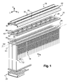
- FIG. 1 and 2 show an evaporator 10 for a motor vehicle air-conditioning system which is operated with CO 2 as refrigerant according to a preferred embodiment of the present invention.
- This evaporator 10 is designed as a two rows flat-tube evaporator and has a multiplicity of flat tubes 12 arranged along two longitudinal rows R1, R2, a front row R1 on the front side of the evaporator 10 and a rear row R2 on the rear side of the evaporator 10.
- These flat tubes 12 can be designed as extruded multi-channel flat tubes, which have a multiplicity of flow passages 14. All the flat tubes 12 have the same length along a vertical axis V and the same depth D along a transverse axis T.
- the flat tubes 12 are multiport extruded flat tubes.
- corrugated fins 16 which are acted on by ambient air in the direction of the arrow F, i.e. along a transverse axis.
- the tubes 12 are fitted between an upper end member constituted of a collector box 18 and a lower end member constituted of a diverter box 20.
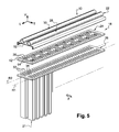
- the collector box 18 comprises a stack of individual plates bearing against one another and including successively a cover plate 22 at the top, an intermediate distribution plate 24, and a header plate 26 at the bottom.
- the collector box 18 comprises also an inlet manifold 28 and an outlet manifold 30 which extends along a longitudinal axis, in parallel to each other, and which are made of one piece with the cover plate 22, the cover plate 22 and the manifolds 28, 30 being extruded.
- cover plate 22 could be stamped and the manifolds 28, 30 could be made from rolled and welded process, and then these separates parts would be brazed together.
- the header plate 26, in which a front row and a rear row of mounting slots 32 are arranged, is illustrated above the flat tubes 12, the two parallel rows of mounting slots 32 corresponding to the two rows R1, R2 of flat tubes 12.
- the mounting slots 32 are located one behind the other in the transverse direction and in each case leave between them webs 34 which separate two adjacent flat tubes 12 in the transverse direction.
- the total number of mounting slots 32 matches with the total number of flat tubes 12, each flat tube upper end 33 being inserted into the header plate 26 through a mounting slot 32.
- the distribution plate 24, or diverter plate, is arranged above the header plate 26 and has distribution slots 36 for refrigerant passage similar to the mounting slots 32.
- the distribution plate 24 comprises, in alternation, two distribution slots 36 forming through passages which lie one behind the other in the transverse direction, leaving a web 40 between them, and a diverter passage 42 which continues through in the transverse direction.
- distribution slots 36 and diverter passages 42 adopts a pattern which repeats itself after four longitudinally adjacent tubes 12, said pattern corresponding to two flow paths 44 through the heat exchanger 10.
- two adjacent flow paths 44 are arranged mirror-symmetrically with respect to one another along the longitudinal axis L. This means that either the distribution slots 36 of a flow path 44 come to lie next to the distribution slots 36 of an adjacent flow path 44, or a diverter passage 42 of a flow path 44 comes to lie next to a diverter passage 42 of an adjacent flow path 44.
- the diverter passages 42 have a cross-over function, allowing the refrigerant to transfer from one row R1 to the next R2 within air stream direction F.
- a flow path 44 of the refrigerant follows the direction of the arrows along the dashed-line 44, i.e. the refrigerant enters the front tube 12 at A passing into the distribution slot 36, initially flows downward, is diverted at the bottom B, then flows upward through a longitudinally adjacent front tube 12 and passes into the diverter passage 42 at C, where it is diverted, before then flowing downward on the rear side of the evaporator 10, where it is diverted at D and then flows upward again in order to pass through the distribution slot 36 of the adjacent rear tube 12 as indicated by arrow E.
- the supply and discharge of the refrigerant is described on the basis of figure 2 .
- each flow path 44 is diverted at the bottom part of the evaporator 10 thanks to the diverter box 20 which is aimed to redirect (at B and D) the flow coming downward through a flat tube 12 towards the longitudinally adjacent flat tube 12 in the upward direction as if the evaporator was formed from individual U-tubes.
- the diverter box 20 is aimed to redirect (at B and D) the flow coming downward through a flat tube 12 towards the longitudinally adjacent flat tube 12 in the upward direction as if the evaporator was formed from individual U-tubes.
- An example of a similar diverter box 20 is disclosed in US 2005/0039901 in connection with figure 1 where it is used for diverting the flow from the front row of tubes towards the rear row of tubes (paragraphs [74] and [75]).
- the diverter box 20 could be omitted by providing the heat exchanger 10 with U-tubes 21, as shown on figure 5 , instead of straight flat tubes 12.
- the U-tube 21 comprises two vertical portions linked at the bottom by a bended portion extending longitudinally.
- the collecting apertures 46, 48 comprise a first row of refrigerant inlet apertures 46 connecting the distribution slots 36 underneath to the inlet manifold 28 and a second row of refrigerant outlet apertures 48 connecting the distribution slots 36 underneath to the outlet manifold 30.
- each collecting aperture 46, 48 is arranged above and between two longitudinally adjacent distribution slots 36 in order to connect jointly said two adjacent distribution slots 36 to the corresponding manifold 28, 30.
- the above-described individual parts of the evaporator 10 are assembled in the following way.
- the header plate 26 is fitted onto the flat-tube ends 33.
- the distribution plate 24 and the cover plate 22 with the manifolds 28, 30 are stacked on top of the header plate 8.
- the different plates constituting the diverter box 20 at the bottom of the evaporator are assembled in a similar way.
- the distribution plate 24 could be integrated into the header plate 26 to save one plate.
- the evaporator 10 After the evaporator 10 has therefore been assembled, it is soldered to form a fixed block in a soldering furnace. During the soldering process, the plates 22, 24, 26 are held in position with respect to one another by a positive or non positive clamping action. However, it is also possible firstly to assemble the end member comprising header plate 26, distribution plate 24, and cover plate 22, and then to connect it to flat tubes 12.
- each collecting aperture 46, 48 is arranged in a main recess 50 provided in the bottom face 52 of the cover plate 22 in order to form, with the upper face 54 of the distribution plate 24, a mixing chamber 56 for the refrigerant.
- said mixing chamber 56 extends partially above the two adjacent distribution slots 36 and said main recess 50 is made longitudinally larger than the collecting aperture 46, 48.
- the recess 50 is made by stamping process into the bottom face 52 of the cover plate 22 which provides the corresponding manifold 28, 30 with a bump 58 on its inner surface 60.
- the bump 58 is delimited transversally by the inner transversal dimension of the manifold 28, 30. More particularly, the bump 58 is delimited transversally by the longitudinal tubular wall 62 of the manifold 28, 30, at the location 63 where the tubular wall 62 is linked to the cover plate 22.
- the vertical depth of the main recess 50 may be approximately the thickness of the metal plate constituting the cover plate 22.
- the main recess 50 has a dome shape which allows an optimized distribution.
- the main recess 50 is of longitudinal oblong shape so that it extends longitudinally from the middle of one distribution slot 36 to the middle of the adjacent distribution slot 36.
- the collecting apertures 46, 48 are preferably designed as bores of transversal oblong shape with dimensions matched to the desired refrigerant distribution and quantitative flow.
- the oblong shape extends transversally which allows a better distribution/collection of the refrigerant into all the channels 14.
- the section of the collecting apertures 46, 48 is preferably ranged between 30% and 60% of the total open area of the tubes 12 to feed. This restriction is done by purpose to make sure the refrigerant flow is more or less constant up to the far end of the manifolds 28, 30.
- the section restriction is adjusted longitudinally, from one collecting aperture 46, 48 to the others, depending on the manifold 28, 30 length and/or depending on refrigerant flow length in the tubes 12.
- the evaporator 10 is designed for obtaining good performances at some predefined operating points which help to define the final value for the section of those collecting apertures 46,48.
- the refrigerant is able to mix before flowing into the two connected tubes 12 which makes the refrigerant more homogenous, in terms of pressure and in terms of fluid consistency, all along the evaporator 10 and all along each flow path 44, thus avoiding risks of flow stratification.
- Flow homogeneity contributes for an optimized distribution in the evaporator 10.
- the refrigerant flow impacts on the portion of the distribution plate 24 which faces the collecting aperture 46, thus contributing to mixing.
- the portion of the distribution plate 24 which faces the collecting aperture 46, 48 is provided with an additional recess 64 for enlarging vertically the mixing chamber 56.
- the additional recess 64 is delimited longitudinally by two adjacent distribution slots 36 and transversally by two lateral surfaces 66, 68 which are facing each other.
- the greater transversal dimension of said additional recess 64 is inferior to the transversal depth of the corresponding through-passages 38.
- each lateral surface 66, 68 defines an increasing flow section towards each of the two adjacent distribution slots 36, the distance between said lateral surfaces 66, 68 increasing towards each of the distribution slots 36.
- each lateral surface 66, 68 has a triangular profile from an elevation view.
- the vertical thickness of the additional recess 64 is inferior to the thickness of the main recess 50.
- the mixing chamber 56 is enlarged backwards and allows better distribution in the tubes 12 of the front row R1, and better collection from the tubes 12 of the rear row R2.
- the invention could be implemented without additional recesses 64.
- the flow restriction provided in the manifolds 28, 30 by the bumps 58 promotes flow turbulences in the manifold 28, 30 which ensure that the refrigerant remain biphasic with an improved flow homogeneity versus stratified one.
- the bumps 58 provide some kind of diaphragm which improves the flow mixing in the manifolds 28, 30.
- the main recesses 50, the bumps 58, and the additional recesses 64 have been described mainly in connection with the inlet manifold 28 and the inlet apertures 46, i.e. in connection with the inlet side or front side of the evaporator 10.
- the main recesses 50, the bumps 58, and the additional recesses 64 can be provided, all together or selectively, on the outlet side or rear side of the evaporator 10, in connection with the outlet manifold 28 and the outlet apertures 48.
Priority Applications (5)
| Application Number | Priority Date | Filing Date | Title |
|---|---|---|---|
| EP08151505A EP2090851A1 (fr) | 2008-02-15 | 2008-02-15 | Échangeur de chaleur doté d'une chambre de mélange |
| AT09710586T ATE523741T1 (de) | 2008-02-15 | 2009-02-06 | Wärmetauscher mit mischkammer |
| US12/867,064 US20100319894A1 (en) | 2008-02-15 | 2009-02-06 | Heat exchanger with a mixing chamber |
| EP09710586A EP2252844B1 (fr) | 2008-02-15 | 2009-02-06 | Échangeur thermique équipé d une chambre de mélange |
| PCT/EP2009/051417 WO2009101035A1 (fr) | 2008-02-15 | 2009-02-06 | Échangeur thermique équipé d’une chambre de mélange |
Applications Claiming Priority (1)
| Application Number | Priority Date | Filing Date | Title |
|---|---|---|---|
| EP08151505A EP2090851A1 (fr) | 2008-02-15 | 2008-02-15 | Échangeur de chaleur doté d'une chambre de mélange |
Publications (1)
| Publication Number | Publication Date |
|---|---|
| EP2090851A1 true EP2090851A1 (fr) | 2009-08-19 |
Family
ID=39789586
Family Applications (2)
| Application Number | Title | Priority Date | Filing Date |
|---|---|---|---|
| EP08151505A Withdrawn EP2090851A1 (fr) | 2008-02-15 | 2008-02-15 | Échangeur de chaleur doté d'une chambre de mélange |
| EP09710586A Active EP2252844B1 (fr) | 2008-02-15 | 2009-02-06 | Échangeur thermique équipé d une chambre de mélange |
Family Applications After (1)
| Application Number | Title | Priority Date | Filing Date |
|---|---|---|---|
| EP09710586A Active EP2252844B1 (fr) | 2008-02-15 | 2009-02-06 | Échangeur thermique équipé d une chambre de mélange |
Country Status (4)
| Country | Link |
|---|---|
| US (1) | US20100319894A1 (fr) |
| EP (2) | EP2090851A1 (fr) |
| AT (1) | ATE523741T1 (fr) |
| WO (1) | WO2009101035A1 (fr) |
Cited By (9)
| Publication number | Priority date | Publication date | Assignee | Title |
|---|---|---|---|---|
| DE102009023954A1 (de) * | 2009-06-04 | 2010-12-09 | Behr Gmbh & Co. Kg | Sammelrohr für einen Kondensator |
| WO2012043565A1 (fr) * | 2010-09-29 | 2012-04-05 | ダイキン工業株式会社 | Échangeur de chaleur |
| EP2447097A3 (fr) * | 2010-10-27 | 2014-09-10 | Behr GmbH & Co. KG | Climatiseur de véhicule à moteur |
| FR3006432A1 (fr) * | 2013-05-28 | 2014-12-05 | Delphi Automotive Systems Lux | Echangeur de chaleur |
| DK201570883A1 (en) * | 2015-12-29 | 2017-04-18 | Dantherm Cooling As | Heat Transfer System or Element with Fewer or No Headers |
| US9995534B2 (en) | 2011-11-29 | 2018-06-12 | Denso Corporation | Heat exchanger |
| EP3457070A1 (fr) * | 2017-09-19 | 2019-03-20 | VALEO AUTOSYSTEMY Sp. Z. o.o. | Collecteur destiné à un ensemble échangeur de chaleur et procédé de fabrication d'un tel collecteur |
| FR3089611A1 (fr) * | 2018-12-10 | 2020-06-12 | Valeo Systemes Thermiques | Boîte collectrice pour echangeur de chaleur et echangeur de chaleur comprenant une telle boîte collectrice |
| EP3907459A1 (fr) * | 2020-05-04 | 2021-11-10 | Valeo Autosystemy SP. Z.O.O. | Échangeur de chaleur |
Families Citing this family (12)
| Publication number | Priority date | Publication date | Assignee | Title |
|---|---|---|---|---|
| US9267737B2 (en) | 2010-06-29 | 2016-02-23 | Johnson Controls Technology Company | Multichannel heat exchangers employing flow distribution manifolds |
| US9151540B2 (en) | 2010-06-29 | 2015-10-06 | Johnson Controls Technology Company | Multichannel heat exchanger tubes with flow path inlet sections |
| JP5287949B2 (ja) * | 2011-07-28 | 2013-09-11 | ダイキン工業株式会社 | 熱交換器 |
| JP5796564B2 (ja) * | 2011-11-30 | 2015-10-21 | 株式会社デンソー | 熱交換器 |
| DE112014002177T5 (de) | 2013-04-24 | 2016-01-07 | Dana Canada Corporation | Lamellenstützstrukturen für Ladeluftkühler |
| AU2013404239B2 (en) * | 2013-10-29 | 2016-11-03 | Mitsubishi Electric Corporation | Heat exchanger and air-conditioning apparatus |
| CN107687727B (zh) * | 2016-08-04 | 2020-03-27 | 丹佛斯微通道换热器(嘉兴)有限公司 | 用于平行流换热器的分配器和平行流换热器 |
| JP7086264B2 (ja) * | 2018-10-29 | 2022-06-17 | 三菱電機株式会社 | 熱交換器、室外機、及び冷凍サイクル装置 |
| WO2020089966A1 (fr) * | 2018-10-29 | 2020-05-07 | 三菱電機株式会社 | Échangeur de chaleur et dispositif à cycle de réfrigération |
| US20200158388A1 (en) * | 2018-11-16 | 2020-05-21 | Mahle International Gmbh | Evaporator unit |
| JPWO2022244091A1 (fr) * | 2021-05-18 | 2022-11-24 | ||
| CN113758056B (zh) * | 2021-09-28 | 2022-12-09 | 西安交通大学 | 一种具有冷媒分配装置的管壳式换热器 |
Citations (3)
| Publication number | Priority date | Publication date | Assignee | Title |
|---|---|---|---|---|
| US20050039901A1 (en) | 2001-12-21 | 2005-02-24 | Walter Demuth | Heat exchanger, particularly for a motor vehicle |
| WO2005038375A1 (fr) * | 2003-10-17 | 2005-04-28 | Behr Gmbh & Co. Kg | Echangeur de chaleur, en particulier pour vehicules automobiles |
| EP1798507A2 (fr) * | 2005-12-13 | 2007-06-20 | Behr GmbH & Co. KG | Echangeur de chaleur, en particulier évaporateur |
Family Cites Families (2)
| Publication number | Priority date | Publication date | Assignee | Title |
|---|---|---|---|---|
| US5241839A (en) * | 1991-04-24 | 1993-09-07 | Modine Manufacturing Company | Evaporator for a refrigerant |
| US7775067B2 (en) * | 2004-03-17 | 2010-08-17 | Showa Denko K.K. | Heat exchanger header tank and heat exchanger comprising same |
-
2008
- 2008-02-15 EP EP08151505A patent/EP2090851A1/fr not_active Withdrawn
-
2009
- 2009-02-06 US US12/867,064 patent/US20100319894A1/en not_active Abandoned
- 2009-02-06 WO PCT/EP2009/051417 patent/WO2009101035A1/fr active Application Filing
- 2009-02-06 AT AT09710586T patent/ATE523741T1/de not_active IP Right Cessation
- 2009-02-06 EP EP09710586A patent/EP2252844B1/fr active Active
Patent Citations (3)
| Publication number | Priority date | Publication date | Assignee | Title |
|---|---|---|---|---|
| US20050039901A1 (en) | 2001-12-21 | 2005-02-24 | Walter Demuth | Heat exchanger, particularly for a motor vehicle |
| WO2005038375A1 (fr) * | 2003-10-17 | 2005-04-28 | Behr Gmbh & Co. Kg | Echangeur de chaleur, en particulier pour vehicules automobiles |
| EP1798507A2 (fr) * | 2005-12-13 | 2007-06-20 | Behr GmbH & Co. KG | Echangeur de chaleur, en particulier évaporateur |
Cited By (16)
| Publication number | Priority date | Publication date | Assignee | Title |
|---|---|---|---|---|
| US9097469B2 (en) | 2009-06-04 | 2015-08-04 | MAHLE Behr GmbH & Co. KG | Header for a condenser |
| DE102009023954A1 (de) * | 2009-06-04 | 2010-12-09 | Behr Gmbh & Co. Kg | Sammelrohr für einen Kondensator |
| WO2012043565A1 (fr) * | 2010-09-29 | 2012-04-05 | ダイキン工業株式会社 | Échangeur de chaleur |
| JP2012093075A (ja) * | 2010-09-29 | 2012-05-17 | Daikin Industries Ltd | 熱交換器 |
| CN103154659A (zh) * | 2010-09-29 | 2013-06-12 | 大金工业株式会社 | 热交换器 |
| CN103154659B (zh) * | 2010-09-29 | 2015-11-25 | 大金工业株式会社 | 热交换器 |
| EP2447097A3 (fr) * | 2010-10-27 | 2014-09-10 | Behr GmbH & Co. KG | Climatiseur de véhicule à moteur |
| US9995534B2 (en) | 2011-11-29 | 2018-06-12 | Denso Corporation | Heat exchanger |
| FR3006432A1 (fr) * | 2013-05-28 | 2014-12-05 | Delphi Automotive Systems Lux | Echangeur de chaleur |
| DK201570883A1 (en) * | 2015-12-29 | 2017-04-18 | Dantherm Cooling As | Heat Transfer System or Element with Fewer or No Headers |
| EP3457070A1 (fr) * | 2017-09-19 | 2019-03-20 | VALEO AUTOSYSTEMY Sp. Z. o.o. | Collecteur destiné à un ensemble échangeur de chaleur et procédé de fabrication d'un tel collecteur |
| WO2019057747A1 (fr) * | 2017-09-19 | 2019-03-28 | Valeo Autosystemy Sp. Z O.O. | Collecteur pour ensemble échangeur de chaleur et procédé de fabrication d'un tel collecteur |
| FR3089611A1 (fr) * | 2018-12-10 | 2020-06-12 | Valeo Systemes Thermiques | Boîte collectrice pour echangeur de chaleur et echangeur de chaleur comprenant une telle boîte collectrice |
| WO2020120894A1 (fr) * | 2018-12-10 | 2020-06-18 | Valeo Systemes Thermiques | Boîte collectrice pour echangeur de chaleur et echangeur de chaleur comprenant une telle boîte collectrice |
| EP3907459A1 (fr) * | 2020-05-04 | 2021-11-10 | Valeo Autosystemy SP. Z.O.O. | Échangeur de chaleur |
| WO2021223944A1 (fr) * | 2020-05-04 | 2021-11-11 | Valeo Autosystemy Sp. Z O.O. | Échangeur de chaleur |
Also Published As
| Publication number | Publication date |
|---|---|
| US20100319894A1 (en) | 2010-12-23 |
| ATE523741T1 (de) | 2011-09-15 |
| WO2009101035A1 (fr) | 2009-08-20 |
| EP2252844A1 (fr) | 2010-11-24 |
| EP2252844B1 (fr) | 2011-09-07 |
Similar Documents
| Publication | Publication Date | Title |
|---|---|---|
| EP2252844B1 (fr) | Échangeur thermique équipé d une chambre de mélange | |
| US9759492B2 (en) | Heat exchanger having additional refrigerant channel | |
| US8590607B2 (en) | Heat exchanger for a motor vehicle | |
| US7484555B2 (en) | Heat exchanger assembly | |
| US8225853B2 (en) | Multi-pass heat exchangers having return manifolds with distributing inserts | |
| US7571761B2 (en) | Heat exchanger | |
| EP2372283B1 (fr) | Échangeur thermique avec plaque collectrice | |
| US7886812B2 (en) | Heat exchanger having a tank partition wall | |
| EP2948725B1 (fr) | Échangeur thermique | |
| CN103890532B (zh) | 扁平管翅片式热交换器以及制造方法 | |
| CN101713604B (zh) | 蒸发器 | |
| EP2810010B1 (fr) | Ensemble échangeur de chaleur à faisceaux de tubes multiplex et procédé de fabrication | |
| WO2006004137A1 (fr) | Evaporateur | |
| US20090007592A1 (en) | Heat exchanger | |
| US8935854B2 (en) | Method of manufacturing heat exchanger | |
| KR20030080004A (ko) | 열교환기 | |
| US9163881B2 (en) | Heat exchanger | |
| US6467536B1 (en) | Evaporator and method of making same | |
| EP2108909A1 (fr) | Échangeur thermique fourni avec un bloc de fixation | |
| US6814135B2 (en) | Stacked-type evaporator | |
| EP3971508B1 (fr) | Échangeur de chaleur | |
| KR20100018477A (ko) | 매니폴드 형성 방법과, 이에 따라 제조된 조립체 | |
| CN205300365U (zh) | 用于换热器的集流管和换热器 | |
| CN212457512U (zh) | 换热组件和换热系统 | |
| US20180149431A1 (en) | Evaporator |
Legal Events
| Date | Code | Title | Description |
|---|---|---|---|
| PUAI | Public reference made under article 153(3) epc to a published international application that has entered the european phase |
Free format text: ORIGINAL CODE: 0009012 |
|
| AK | Designated contracting states |
Kind code of ref document: A1 Designated state(s): AT BE BG CH CY CZ DE DK EE ES FI FR GB GR HR HU IE IS IT LI LT LU LV MC MT NL NO PL PT RO SE SI SK TR |
|
| AX | Request for extension of the european patent |
Extension state: AL BA MK RS |
|
| AKX | Designation fees paid | ||
| REG | Reference to a national code |
Ref country code: DE Ref legal event code: 8566 |
|
| STAA | Information on the status of an ep patent application or granted ep patent |
Free format text: STATUS: THE APPLICATION IS DEEMED TO BE WITHDRAWN |
|
| 18D | Application deemed to be withdrawn |
Effective date: 20100220 |