EP2090817B1 - Double walled corrugated pipe section with pipe coupling - Google Patents
Double walled corrugated pipe section with pipe coupling Download PDFInfo
- Publication number
- EP2090817B1 EP2090817B1 EP09152692A EP09152692A EP2090817B1 EP 2090817 B1 EP2090817 B1 EP 2090817B1 EP 09152692 A EP09152692 A EP 09152692A EP 09152692 A EP09152692 A EP 09152692A EP 2090817 B1 EP2090817 B1 EP 2090817B1
- Authority
- EP
- European Patent Office
- Prior art keywords
- pipe
- wall
- connector
- corrugations
- insert connector
- Prior art date
- Legal status (The legal status is an assumption and is not a legal conclusion. Google has not performed a legal analysis and makes no representation as to the accuracy of the status listed.)
- Active
Links
- 230000008878 coupling Effects 0.000 title description 9
- 238000010168 coupling process Methods 0.000 title description 9
- 238000005859 coupling reaction Methods 0.000 title description 9
- 239000004033 plastic Substances 0.000 claims abstract description 21
- 229920003023 plastic Polymers 0.000 claims abstract description 21
- 230000007704 transition Effects 0.000 claims description 33
- 238000010276 construction Methods 0.000 claims description 6
- 229920000114 Corrugated plastic Polymers 0.000 claims description 2
- 238000007789 sealing Methods 0.000 description 4
- 238000000034 method Methods 0.000 description 3
- 238000013459 approach Methods 0.000 description 2
- 230000002787 reinforcement Effects 0.000 description 2
- 230000003014 reinforcing effect Effects 0.000 description 2
- 239000002131 composite material Substances 0.000 description 1
- 238000001125 extrusion Methods 0.000 description 1
- 230000000977 initiatory effect Effects 0.000 description 1
- 238000003780 insertion Methods 0.000 description 1
- 230000037431 insertion Effects 0.000 description 1
- 238000009434 installation Methods 0.000 description 1
- 238000004519 manufacturing process Methods 0.000 description 1
- 239000000463 material Substances 0.000 description 1
- 238000005259 measurement Methods 0.000 description 1
- 239000002184 metal Substances 0.000 description 1
- 239000002991 molded plastic Substances 0.000 description 1
- 238000000465 moulding Methods 0.000 description 1
- 230000002035 prolonged effect Effects 0.000 description 1
- 229920001169 thermoplastic Polymers 0.000 description 1
- 239000004416 thermosoftening plastic Substances 0.000 description 1
Images
Classifications
-
- F—MECHANICAL ENGINEERING; LIGHTING; HEATING; WEAPONS; BLASTING
- F16—ENGINEERING ELEMENTS AND UNITS; GENERAL MEASURES FOR PRODUCING AND MAINTAINING EFFECTIVE FUNCTIONING OF MACHINES OR INSTALLATIONS; THERMAL INSULATION IN GENERAL
- F16L—PIPES; JOINTS OR FITTINGS FOR PIPES; SUPPORTS FOR PIPES, CABLES OR PROTECTIVE TUBING; MEANS FOR THERMAL INSULATION IN GENERAL
- F16L25/00—Constructive types of pipe joints not provided for in groups F16L13/00 - F16L23/00 ; Details of pipe joints not otherwise provided for, e.g. electrically conducting or insulating means
- F16L25/0036—Joints for corrugated pipes
- F16L25/0063—Joints for corrugated pipes with two corrugated pipes being directly connected to each other
-
- F—MECHANICAL ENGINEERING; LIGHTING; HEATING; WEAPONS; BLASTING
- F16—ENGINEERING ELEMENTS AND UNITS; GENERAL MEASURES FOR PRODUCING AND MAINTAINING EFFECTIVE FUNCTIONING OF MACHINES OR INSTALLATIONS; THERMAL INSULATION IN GENERAL
- F16L—PIPES; JOINTS OR FITTINGS FOR PIPES; SUPPORTS FOR PIPES, CABLES OR PROTECTIVE TUBING; MEANS FOR THERMAL INSULATION IN GENERAL
- F16L47/00—Connecting arrangements or other fittings specially adapted to be made of plastics or to be used with pipes made of plastics
- F16L47/06—Connecting arrangements or other fittings specially adapted to be made of plastics or to be used with pipes made of plastics with sleeve or socket formed by or in the pipe end
- F16L47/08—Connecting arrangements or other fittings specially adapted to be made of plastics or to be used with pipes made of plastics with sleeve or socket formed by or in the pipe end with sealing rings arranged between the outer surface of one pipe end and the inner surface of the sleeve or socket, the sealing rings being placed previously in the sleeve or socket
Definitions
- the present invention relates to double wall corrugated pipes and methods for manufacturing of such pipes with coupling components.
- Double wall corrugated pipe is typically formed in a moving mold tunnel where two streams of plastic are shaped to form inner and outer walls of the corrugated pipe.
- the inner wall of the double wall corrugated pipe is of a fixed diameter defining a smooth consistent passageway through the pipe.
- the outer wall of the pipe is formed with a series of circumferentially extending corrugations to stiffen the pipe and increase the buckling strength thereof.
- the integrally molded pipe includes pipe sections with an insert connector and a bell connector separating the pipe sections.
- the continuous length of pipe produced by the process is cut into lengths of pipe with each pipe having an insert connector at one end thereof and a bell connector at an opposite end.
- the insert connector includes a series of corrugations along its length.
- the insert connector is sized for receipt within the bell connection.
- the corrugations of the insert connector portion are preferably smaller than the corrugations of the pipe sections and the bell connector is preferably of a diameter corresponding to the corrugations of the pipe sections.
- a seal is provided about an exterior surface of the insert connector or on one of the corrugations associated with the insert connector.
- the inner wall at the junction of two connected pipe lengths is discontinuous between the end of the insert connector and a transition wall between the pipe section and the bell connector.
- the outer wall of the corrugations of the insert connector can include a number of gaps or deformations and leakage can occur between a seal provided on the top surface of a corrugation of the insert connector.
- the shape configuration of the surface that receives the seal varies as a function of the molded plastic and operating parameters of the molding system. It is quite common to have small irregularities in this surface.
- US 2004/262923 discloses a pipe assembly having a first pipe section and a second pipe section of which at least one pipe section is provided with a spigot which is provided with outwardly annularly extending projections with flanks. A seal is arranged between two adjacent projections against their flanks. At least those projections between which the seal is arranged are formed as projections of increased wall thickness forming a portion of increased wall thickness and comprising a higher filling ratio than more distantly arranged projections.
- US 5,996,635 is directed at a composite pipe having an internal pipe and a corrugated external pipe and a socket formed in one piece with the internal pipe and the external pipe.
- This socket has a connecting section of substantially cylindrical shape and at least one reinforcing rib formed on the outside of the connecting section, a ⁇ 2b applying to the length b of the reinforcing rib in the direction of the central longitudinal axis in relation to its thickness a radial to the central longitudinal axis.
- EP 1 217 282 A1 shows a thermoplastic pipe of the type with a double wall structure, specifically a cylindrical smooth inner wall and a corrugated outer wall, which at one of the ends of the pipe is prolonged beyond the inner wall in a smooth area with an appropriate diameter to receive the opposite end of another section of pipe inside, a watertight joint being inserted.
- a ring-shaped reinforcement band which may be made of plastic or metal and which will be variable in both thickness and in its axial measurement, according to the diameter of the pipes to be joined and to the circumferential stiffness of the same.
- the present invention seeks to overcome a number of disadvantageous associated with our earlier structure and prior art approaches used to connect double wall corrugated pipe.
- a corrugated plastic pipe of a double wall construction comprises a continuous inner wall defining a consistent passageway through the pipe and an outer wall forming corrugations connected to the inner wall at an inner edge of each corrugation.
- the pipe at one end thereof includes a bell connector and at an opposite end includes an insert connector having a series of corrugations and an inner wall corresponding to the inner wall of the pipe.
- the bell connector includes a transition wall extending from a common junction of the inner and outer walls of the pipe to an outer sleeve sized to receive the insert connector.
- the insert connector includes a lead corrugation at a free end of the insert connector with a lead wall angled to cooperate and engage a transition segment of a bell connector of a like configured pipe when inserted therein.
- the inner wall of the insert connector projects in a longitudinal axial direction of the pipe end portion beyond the lead corrugation to form an end portion acting as a connecting transition of the inner walls between two pipes connected with the insert connector of one pipe inserted in the bell connector of the second pipe.
- the lead wall of the lead corrugation is of a length greater than the lead wall of the following corrugations of the insert connector.
- the end portion of the insert connector is a stub flange.
- the outer sleeve includes a generally smooth inner wall with a series of circumferentially extending ribs on an exterior surface of the outer sleeve.
- an exterior surface of the transition segment includes a series of ribs extending circumferentially about the transition segment.
- the outer sleeve between a free end and the transition segment is of a single wall thickness.
- the free end of the outer sleeve is shaped to receive an insert connector of a like-configured pipe.
- the free end of the outer sleeve includes an outwardly flared interior wall providing a lead-in portion for receiving a insert connector.
- the corrugations of the insert connector are of reduced size defining a smaller exterior diameter relative to the exterior diameter of the pipe corrugations.
- the outer sleeve is of a diameter corresponding to a maximum diameter of the pipe corrugations.
- the insert connector includes corrugations of a smaller size that are receivable within the outer sleeve.
- the insert connector includes the lead corrugation and at least two intermediate corrugations spaced along the length of the insert connector.
- an "O" ring seal is provided on the insert connector between the lead corrugation and the intermediate corrugation that is adjacent to the lead corrugation.
- the transition segment is disposed at an angle of approximately 45° relative to a longitudinal axis of the pipe section.
- the stub flange of the insert connector has an angle end-face parallel to an inner surface of the transition segment whereby the stub flange can abut with the inner surface along the angled end-face.
- FIG. 7 shows a prior art pipe wall construction generally indicated at 101.
- This pipe wall construction is formed from a common source of plastic separated into different streams through an extrusion process as is known in the art.
- the wall construction comprises an inner pipe wall 103 formed from the first stream of plastic and an outer pipe wall 105 formed from the second stream of plastic.
- the inner pipe wall is flat except where the pipe wall is formed with a bowed wall part 109.
- the outer pipe wall is formed with a series of corrugations except at the bowed wall part 109 where the inner and outer pipe walls conform with one another.
- the outer pipe wall 105 is formed into corrugations. However, these corrugations vary in diameter lengthwise of the pipe. Specifically, along major portions 107 of the length of the pipe, the outer wall is formed into corrugations 108 and along minor portions 113 of the length of the pipe, the outer wall is formed into corrugations 114. These minor portions 113 of the pipe wall also include the bowed wall part 109.
- the corrugations 108 have a larger diameter than the corrugations 114, the corrugations 114 have a greater wall thickness as both corrugations are made with the same amount of plastic material.
- Bowed wall part 109 has a transition area 111 where it meets with the small diameter corrugations 114.
- the removal of this transition area defined by cut positions 130 and 132, produces two separate pipe sections.
- One pipe section includes a bell 109a which has been converted from the bowed wall part 109 through the removal of the transition area 111 of the bowed wall part.
- This transition region removal also produces a male spigot end wall construction 113 as shown in Figure 8 where the spigot is formed by the small diameter corrugations 114.
- Figure 8 of the drawings shows that a seal 115 is placed into one of the valleys of the corrugations 114.
- the gap 119 forms an interruption band and the inner pipe wall 103 is discontinuous.
- the shape of the end corrugation 114 is difficult to control as this is the first corrugation formed after the transition area 111 joins the bowed wall part 109 to the first corrugation. Subsequent corrugations 114 tend to be more accurate. This is not the most advantageous arrangement as sealing of the two pipe sections is more difficult.
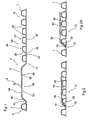
- Figure 1 illustrates an improved continuous length of molded pipe product 2 having a first pipe section 4 a second pipe section 6 that are interconnected by the bell connector 8, a scrap or removable section 12 and the male insert connector 10.
- the continuous molded pipe product is cut at cut line 14 and at the angled cut line 16 to separate the continuous molded pipe product into predetermined lengths of pipe.
- the angled cut line 16 is provided at a common junction of the inner and outer walls in front of a lead corrugation 36 of the insert connector. This arrangement defines a short stub flange 18.
- the insert connector 10 includes an inner wall 30 and an outer corrugated wall 32.
- the lead corrugation 36 is provided at a free end of the insert connector and preferably includes two associated intermediate corrugations 42.
- the lead corrugation 36 includes an angled lead wall 38 that generally corresponds with the angled transition segment or wall 46 of the bell connector.
- the angled transition wall 46 merges with an outer sleeve 50 of the bell connector.
- the outer sleeve 50 includes exterior ribs 52 provided at different locations along the length of the outer sleeve as well as a non-ribbed seal section 54 that is positioned adjacent a sealing portion on the insert connector.
- the non-ribbed seal section 54 includes an inner wall 53 which is of more consistent diameter and less subject to undulations 55 (see Figure 4 ) in the wall which are more commonly associated with the ribbed portion of the outer sleeve 50. Additional details of this are shown in the enlarged sectional view of Figure 4 .
- the outer sleeve 50 of the bell connector includes a free end 58 that includes an outwardly flared wall 60 that provides a lead-in for receiving the insert connector 10.
- the scrap or forming transition section 12 is removed but provides a short forming transition between the outer sleeve 50 of the bell connector 8 and the free end of the insert connector 10 including the stub flange 18 and the lead wall 38 of the lead corrugation 36.
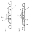
- the continuous molded pipe product of Figure 1 has been cut into two lengths of pipe with the insert connector 10 of one pipe inserted in the bell connector 8 of a second pipe.
- the lead wall 38 of the lead corrugation 36 generally corresponds with the transition wall 46 of the outer sleeve 50.
- the stub flange 18 of the insert connector cooperates with the bell connector at the base of the transition wall 46 and the last corrugation of the pipe section.
- the inner walls of the connected pipes are generally continuous and there is no substantial gap at the junction of the stub flange 18 and the abutment with the transition wall 46.
- the lead corrugation 36 and the associated intermediate corrugations 42 are of reduced diameter relative to the conventional pipe corrugations 7.
- the outer sleeve 50 is of the same diameter as the conventional pipe corrugations 7.
- Figure 2A shows a connection where the diameter and shape of the corrugations of the insert connector 10 generally correspond with the diameter and shape of the conventional corrugations 7 of the pipes with the exception that the insert connector includes the specialized lead corrugation 36 for cooperation with the transition wall 46 of the bell connector.
- the outer sleeve 50 is of slightly increased diameter relative to the maximum diameter of the intermediate corrugations of the pipes.
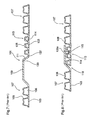
- an "O" ring seal 76 is preferably inserted as generally shown in Figure 3A .
- the "O" ring seal 76 has a force fit with the exterior walls of the lead corrugation 36 and the first intermediate corrugation of the insert connector and the seal also engages with the inner wall of the non-ribbed seal section 54 of the outer sleeve 50.
- This inner wall is generally continuous and is subject to less deformation and therefore a better seal is provided.
- the additional ribs on the transition wall 46 and on the outer sleeve 50 provide additional strength and reinforcement. These ribs are not provided in the location of the seal.
- the lead wall of the lead corrugation is of a length greater than the lead wall of the following corrugations.
- the lead wall 38 is at an angle of about 45° whereas the lead wall of other corrugations is much steeper to provide additional stiffness.
- the first intermediate corrugation 80 has been deformed on a top surface and has been provided with the "O" ring seal 76a that is seated within this depression of the corrugation.
- the outer sleeve 50 of the bell connector has the non-ribbed portion 54a positioned to engage the "O" ring seal 76a. This provides improved sealing of the insert connector with the bell connector.
- the stub flange 18 is generally in abutment with the inner wall of the first pipe. As previously stated this provides better flow through the connected pipes and also reduces leakage.
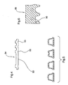
- Figure 4 shows the details of the ribbing of the outer sleeve and in particular how the non-ribbed portion 54 includes a smoother interior wall.
- the forming of the ribs requires a vacuum force applied to the plastic to draw the ribs into the mold block. This provides or forms a small deformation on the inner wall.
- the non-ribbed seal portion 54 By having the non-ribbed seal portion 54, the inner wall at the seal is smooth and a better seal is achieved.
- Figure 5 is a cross-sectional view through a number of different corrugations 89 and is provided to illustrate that the corrugations of both the pipe and the insert connector can be of different shapes.
- Figure 6 shows a partial mold block 89 with an insertion piece 90 used to form the transition wall of the bell connector.
- a similar type insert can be used for forming of the lead corrugation of the insert connector. Such inserts allow a cost effective approach to adapt existing or more common shaped mold blocks.
Abstract
Description
- The present invention relates to double wall corrugated pipes and methods for manufacturing of such pipes with coupling components.
- Double wall corrugated pipe is typically formed in a moving mold tunnel where two streams of plastic are shaped to form inner and outer walls of the corrugated pipe.
Preferably, the inner wall of the double wall corrugated pipe is of a fixed diameter defining a smooth consistent passageway through the pipe. The outer wall of the pipe is formed with a series of circumferentially extending corrugations to stiffen the pipe and increase the buckling strength thereof. - Our previous Canadian Patent
2,342,360 discloses a double wall corrugated pipe that is formed using a continuous moving mold tunnel to form a continuous length of pipe. The integrally molded pipe includes pipe sections with an insert connector and a bell connector separating the pipe sections. With this arrangement the continuous length of pipe produced by the process, is cut into lengths of pipe with each pipe having an insert connector at one end thereof and a bell connector at an opposite end. Preferably the insert connector includes a series of corrugations along its length. The insert connector is sized for receipt within the bell connection. The corrugations of the insert connector portion are preferably smaller than the corrugations of the pipe sections and the bell connector is preferably of a diameter corresponding to the corrugations of the pipe sections. In this way two connected pipe sections form an extended length of pipe where the maximum diameter of the connected pipe is generally constant (See Prior ArtFigures 7 and 8 ). - It has also been known to have the bell connector slightly enlarged for receiving a insert connector with corrugations the same size as the corrugations of the pipe section. With this arrangement the coupling between two pipe sections is of a slightly increased diameter relative to the pipe sections either side of the coupling.
- In a continuous length of pipe formed with an insert connector adjacent to a bell connector, there is a short length of the molded pipe that is removed between the insert connector and the bell connector to position the connectors at the end of two lengths of pipe.
- With the insert/bell coupling as disclosed in our earlier patent 2,342,360, a seal is provided about an exterior surface of the insert connector or on one of the corrugations associated with the insert connector. The inner wall at the junction of two connected pipe lengths is discontinuous between the end of the insert connector and a transition wall between the pipe section and the bell connector.
- It is preferable to include a mechanical type seal between the insert and bell connector as this type of seal is easily completed in the field during installation of the pipe. This type of pipe system is commonly used in association with drainage applications.
- It has been found that the outer wall of the corrugations of the insert connector can include a number of gaps or deformations and leakage can occur between a seal provided on the top surface of a corrugation of the insert connector. The shape configuration of the surface that receives the seal varies as a function of the molded plastic and operating parameters of the molding system. It is quite common to have small irregularities in this surface.
-
US 2004/262923 discloses a pipe assembly having a first pipe section and a second pipe section of which at least one pipe section is provided with a spigot which is provided with outwardly annularly extending projections with flanks. A seal is arranged between two adjacent projections against their flanks. At least those projections between which the seal is arranged are formed as projections of increased wall thickness forming a portion of increased wall thickness and comprising a higher filling ratio than more distantly arranged projections. -
US 5,996,635 is directed at a composite pipe having an internal pipe and a corrugated external pipe and a socket formed in one piece with the internal pipe and the external pipe. This socket has a connecting section of substantially cylindrical shape and at least one reinforcing rib formed on the outside of the connecting section, a ≤ 2b applying to the length b of the reinforcing rib in the direction of the central longitudinal axis in relation to its thickness a radial to the central longitudinal axis. -
EP 1 217 282 A1 shows a thermoplastic pipe of the type with a double wall structure, specifically a cylindrical smooth inner wall and a corrugated outer wall, which at one of the ends of the pipe is prolonged beyond the inner wall in a smooth area with an appropriate diameter to receive the opposite end of another section of pipe inside, a watertight joint being inserted. Its characteristics arise from the fact that in the said smooth terminal section it incorporates a ring-shaped reinforcement band, which may be made of plastic or metal and which will be variable in both thickness and in its axial measurement, according to the diameter of the pipes to be joined and to the circumferential stiffness of the same. - The present invention seeks to overcome a number of disadvantageous associated with our earlier structure and prior art approaches used to connect double wall corrugated pipe.
- A corrugated plastic pipe of a double wall construction according to the present invention comprises a continuous inner wall defining a consistent passageway through the pipe and an outer wall forming corrugations connected to the inner wall at an inner edge of each corrugation. The pipe at one end thereof includes a bell connector and at an opposite end includes an insert connector having a series of corrugations and an inner wall corresponding to the inner wall of the pipe. The bell connector includes a transition wall extending from a common junction of the inner and outer walls of the pipe to an outer sleeve sized to receive the insert connector. The insert connector includes a lead corrugation at a free end of the insert connector with a lead wall angled to cooperate and engage a transition segment of a bell connector of a like configured pipe when inserted therein. The inner wall of the insert connector, at the free end, projects in a longitudinal axial direction of the pipe end portion beyond the lead corrugation to form an end portion acting as a connecting transition of the inner walls between two pipes connected with the insert connector of one pipe inserted in the bell connector of the second pipe. The lead wall of the lead corrugation is of a length greater than the lead wall of the following corrugations of the insert connector.
- According to an aspect of the invention the end portion of the insert connector is a stub flange.
- In a further aspect of the invention the outer sleeve includes a generally smooth inner wall with a series of circumferentially extending ribs on an exterior surface of the outer sleeve.
- In a further aspect of the invention, an exterior surface of the transition segment includes a series of ribs extending circumferentially about the transition segment.
- In yet a further aspect of the invention, the outer sleeve between a free end and the transition segment is of a single wall thickness.
- In yet a further aspect of the invention, the free end of the outer sleeve is shaped to receive an insert connector of a like-configured pipe.
- In yet a further aspect of the invention, the free end of the outer sleeve includes an outwardly flared interior wall providing a lead-in portion for receiving a insert connector.
- In yet a further aspect of the invention, the corrugations of the insert connector are of reduced size defining a smaller exterior diameter relative to the exterior diameter of the pipe corrugations.
- In a different aspect of the invention, the outer sleeve is of a diameter corresponding to a maximum diameter of the pipe corrugations. With this arrangement the insert connector includes corrugations of a smaller size that are receivable within the outer sleeve.
- In yet a further aspect of the invention, the insert connector includes the lead corrugation and at least two intermediate corrugations spaced along the length of the insert connector.
- In a further aspect of the invention, an "O" ring seal is provided on the insert connector between the lead corrugation and the intermediate corrugation that is adjacent to the lead corrugation.
- In yet a further aspect of the invention, the transition segment is disposed at an angle of approximately 45° relative to a longitudinal axis of the pipe section.
- In yet a further aspect of the invention, the stub flange of the insert connector has an angle end-face parallel to an inner surface of the transition segment whereby the stub flange can abut with the inner surface along the angled end-face. With this arrangement the inner wall at the junction of two connected pipe sections is generally continuous.
- Preferred embodiments of the invention are shown in the drawings wherein:
-
Figure 1 is a partial sectional view through a length of double wall corrugated pipe product with a bell connector and an insert connector prior to the pipe section being cut into lengths of pipe; -
Figure 2 is a partial cross-sectional view showing the coupling of two lengths of pipe using the insert connector and a bell connector; -
Figure 2A is a partial cross-sectional view through the connection between the bell connector and the insert connector where the corrugations of the insert connector are of the same diameter as the corrugations of the pipe and the bell connector is of slightly greater diameter; -
Figure 3 is a partial cross-sectional view of the insert/bell connection and an "O" ring provided between a lead corrugation and an intermediate corrugation of the insert connector; -
Figure 3A shows a connection of the bell connector and the insert connector where the insert connector is of reduced diameter and a seal is provided on a surface of one of the corrugations of the insert connector; -
Figure 4 is a partial sectional view showing details of an outer sleeve of the bell connector; -
Figure 5 shows a series of pipe corrugations of different shapes; -
Figure 6 is a partial sectional view through a mold block showing the adaption of the mold block to define a transition segment used to form the insert connector; -
Figure 7 is a partial sectional view of a prior art length of double wall corrugated pipe prior to the pipe being cut to length; and -
Figure 8 is a partial cross section of the prior art pipe ofFigure 7 showing the coupling of two lengths of pipe. -
Figure 7 shows a prior art pipe wall construction generally indicated at 101. This pipe wall construction is formed from a common source of plastic separated into different streams through an extrusion process as is known in the art. - The wall construction comprises an
inner pipe wall 103 formed from the first stream of plastic and anouter pipe wall 105 formed from the second stream of plastic. The inner pipe wall is flat except where the pipe wall is formed with a bowedwall part 109. The outer pipe wall is formed with a series of corrugations except at the bowedwall part 109 where the inner and outer pipe walls conform with one another. - The
outer pipe wall 105 is formed into corrugations. However, these corrugations vary in diameter lengthwise of the pipe. Specifically, alongmajor portions 107 of the length of the pipe, the outer wall is formed intocorrugations 108 and alongminor portions 113 of the length of the pipe, the outer wall is formed intocorrugations 114. Theseminor portions 113 of the pipe wall also include the bowedwall part 109. - The
corrugations 108 have a larger diameter than thecorrugations 114, thecorrugations 114 have a greater wall thickness as both corrugations are made with the same amount of plastic material. - Bowed
wall part 109 has atransition area 111 where it meets with thesmall diameter corrugations 114. The removal of this transition area, defined bycut positions bell 109a which has been converted from the bowedwall part 109 through the removal of thetransition area 111 of the bowed wall part. This transition region removal also produces a male spigotend wall construction 113 as shown inFigure 8 where the spigot is formed by thesmall diameter corrugations 114.Figure 8 of the drawings shows that aseal 115 is placed into one of the valleys of thecorrugations 114. Thebell 109a of the pipe wall section is then slid over thespigot forming corrugations 114 of the pipe wall end of the other pipe section as shown inFigure 8 . This produces a sealed coupling of the two pipe ends relative to one another. The increased wall thickness of the spigot forming corrugations makes them strong to maintain the seal in the coupling. - Although the prior art arrangement of
Figures 7 and 8 is satisfactory in many applications, thegap 119 forms an interruption band and theinner pipe wall 103 is discontinuous. Also, the shape of theend corrugation 114 is difficult to control as this is the first corrugation formed after thetransition area 111 joins the bowedwall part 109 to the first corrugation.Subsequent corrugations 114 tend to be more accurate. This is not the most advantageous arrangement as sealing of the two pipe sections is more difficult. -
Figure 1 illustrates an improved continuous length of moldedpipe product 2 having a first pipe section 4 a second pipe section 6 that are interconnected by thebell connector 8, a scrap orremovable section 12 and themale insert connector 10. The continuous molded pipe product is cut atcut line 14 and at theangled cut line 16 to separate the continuous molded pipe product into predetermined lengths of pipe. Theangled cut line 16 is provided at a common junction of the inner and outer walls in front of alead corrugation 36 of the insert connector. This arrangement defines ashort stub flange 18. - The
insert connector 10 includes aninner wall 30 and an outercorrugated wall 32. The lead corrugation 36 is provided at a free end of the insert connector and preferably includes two associatedintermediate corrugations 42. - The lead corrugation 36 includes an
angled lead wall 38 that generally corresponds with the angled transition segment orwall 46 of the bell connector. Theangled transition wall 46 merges with anouter sleeve 50 of the bell connector. Theouter sleeve 50 includesexterior ribs 52 provided at different locations along the length of the outer sleeve as well as anon-ribbed seal section 54 that is positioned adjacent a sealing portion on the insert connector. Basically thenon-ribbed seal section 54 includes aninner wall 53 which is of more consistent diameter and less subject to undulations 55 (seeFigure 4 ) in the wall which are more commonly associated with the ribbed portion of theouter sleeve 50. Additional details of this are shown in the enlarged sectional view ofFigure 4 . - The
outer sleeve 50 of the bell connector includes afree end 58 that includes an outwardly flaredwall 60 that provides a lead-in for receiving theinsert connector 10. - The scrap or forming
transition section 12 is removed but provides a short forming transition between theouter sleeve 50 of thebell connector 8 and the free end of theinsert connector 10 including thestub flange 18 and thelead wall 38 of thelead corrugation 36. - The continuous molded pipe product of
Figure 1 has been cut into two lengths of pipe with theinsert connector 10 of one pipe inserted in thebell connector 8 of a second pipe. Thelead wall 38 of thelead corrugation 36 generally corresponds with thetransition wall 46 of theouter sleeve 50. Thestub flange 18 of the insert connector cooperates with the bell connector at the base of thetransition wall 46 and the last corrugation of the pipe section. As shown at 72 inFigures 2 and 2A , the inner walls of the connected pipes are generally continuous and there is no substantial gap at the junction of thestub flange 18 and the abutment with thetransition wall 46. Preferably there is no large gap provided between the inner wall of the lead corrugation and the inner wall of the pipe at the initiation of the bell connector. With this arrangement improved sealing and improved flow through two connected pipe sections is achieved. - In
Figures 1 and 2 thelead corrugation 36 and the associatedintermediate corrugations 42 are of reduced diameter relative to theconventional pipe corrugations 7. Theouter sleeve 50 is of the same diameter as theconventional pipe corrugations 7. -
Figure 2A shows a connection where the diameter and shape of the corrugations of theinsert connector 10 generally correspond with the diameter and shape of theconventional corrugations 7 of the pipes with the exception that the insert connector includes thespecialized lead corrugation 36 for cooperation with thetransition wall 46 of the bell connector. Theouter sleeve 50 is of slightly increased diameter relative to the maximum diameter of the intermediate corrugations of the pipes. - Between the
lead corrugation 36 and the first intermediate corrugation following the lead corrugation, an "O"ring seal 76 is preferably inserted as generally shown inFigure 3A . The "O"ring seal 76 has a force fit with the exterior walls of thelead corrugation 36 and the first intermediate corrugation of the insert connector and the seal also engages with the inner wall of thenon-ribbed seal section 54 of theouter sleeve 50. This inner wall is generally continuous and is subject to less deformation and therefore a better seal is provided. The additional ribs on thetransition wall 46 and on theouter sleeve 50 provide additional strength and reinforcement. These ribs are not provided in the location of the seal. - The lead wall of the lead corrugation is of a length greater than the lead wall of the following corrugations. Preferably the
lead wall 38 is at an angle of about 45° whereas the lead wall of other corrugations is much steeper to provide additional stiffness. For example, inFigure 3 the firstintermediate corrugation 80 has been deformed on a top surface and has been provided with the "O"ring seal 76a that is seated within this depression of the corrugation. Theouter sleeve 50 of the bell connector has thenon-ribbed portion 54a positioned to engage the "O"ring seal 76a. This provides improved sealing of the insert connector with the bell connector. As shown, thestub flange 18 is generally in abutment with the inner wall of the first pipe. As previously stated this provides better flow through the connected pipes and also reduces leakage. -
Figure 4 shows the details of the ribbing of the outer sleeve and in particular how thenon-ribbed portion 54 includes a smoother interior wall. Basically the forming of the ribs requires a vacuum force applied to the plastic to draw the ribs into the mold block. This provides or forms a small deformation on the inner wall. By having thenon-ribbed seal portion 54, the inner wall at the seal is smooth and a better seal is achieved. -
Figure 5 is a cross-sectional view through a number ofdifferent corrugations 89 and is provided to illustrate that the corrugations of both the pipe and the insert connector can be of different shapes. -
Figure 6 shows apartial mold block 89 with aninsertion piece 90 used to form the transition wall of the bell connector. A similar type insert can be used for forming of the lead corrugation of the insert connector. Such inserts allow a cost effective approach to adapt existing or more common shaped mold blocks. - Although preferred embodiments of the invention have been described herein in detail, it will be understood by those skilled in the art, that variations may be made thereto without departing from the invention or the scope of the appended claims.
Claims (14)
- Corrugated plastic pipe (2) of a double wall construction, said pipe (2) comprising
a continuous inner wall (30) defining a consistent passageway through said pipe and an outer wall (32) forming corrugations (7) connected to said inner wall (30) at an inner edge of each corrugation (7);
said pipe (2) at one end thereof including a bell connector (8) and at an opposite end including an insert connector (10) having a series of corrugations (36, 42) and an inner wall corresponding to said inner wall (30) of said pipe (2);
said bell connector (8) including a transition wall (46) extending from a common junction of the inner and outer walls (30, 32) of said pipe (2) to an outer sleeve (50) sized to receive said insert connector (10);
said insert connector (10) including a lead corrugation (36) at a free end (58) of said insert connector (10) with a lead wall (38) angled to cooperate and engage a transition segment of a bell connector of a like configured pipe when inserted therein;
said inner wall (10) of said insert connector, at said free end (58), projecting in a longitudinal axial direction of said pipe end portion beyond said lead corrugation (36) to form an end portion acting as a connecting transition of the inner walls (30) between two pipes connected with the insert connector (10) of one pipe (2) inserted in the bell connector of the second pipe;
characterized in that the lead wall (38) of the lead corrugation (36) is of a length greater than the lead wall of the following corrugations of the insert connector (10). - Plastic pipe as claimed in claim 1 wherein said end portion is a stub flange.
- Plastic pipe as claimed in claim 1 wherein said outer sleeve (50) includes a generally smooth inner wall with a series of circumferentially extending ribs (52) on an exterior surface of said outer sleeve (50).
- Plastic pipe as claimed in claim 1, 2 or 3 wherein an exterior surface of said transition wall (46) includes a series of ribs (40) extending circumferentially about said transition wall (46).
- Plastic pipe as claimed in claim 3 or 4 wherein said outer sleeve (50) between a free end and said transition segment is of a single wall thickness.
- Plastic pipe as claimed in claim 5 wherein said free end (58) of said outer sleeve (50) is outwardly shaped to facilitate receipt of an insert connector of a like configured pipe.
- Plastic pipe as claimed in claim 6 wherein said free end (58) includes an outwardly flared interior wall providing a lead-in for receiving an insert connector.
- Plastic pipe as claimed in claim 1 wherein said corrugations (42) of said insert connector (10) are of a reduced size defining a smaller exterior diameter relative to the exterior diameter of said pipe corrugations (7).
- Plastic pipe as claimed in claim 8 wherein said outer sleeve (50) is of an inner diameter corresponding to a maximum diameter of said pipe corrugations (7).
- Plastic pipe as claimed in claim 1 wherein said insert connector (10) includes said lead corrugation (36) and at least two intermediate corrugations (42) along a length of said insert connector (10).
- Plastic pipe as claimed in claim 10 including an 'O' ring seal maintained on said insert connector (10) between said lead corrugation (36) and said intermediate corrugation (42) that is adjacent thereto.
- Plastic pipe as claimed in claim 1 wherein said transition segment is disposed at an angle of approximately 45° relative to a longitudinal axis of said pipe (2).
- Plastic pipe as claimed in claim 2 wherein said stub flange has an angled end face substantially parallel to an inner surface of said transition segment for abutment therewith along said angled end face.
- Plastic pipe as claimed in claim 1 wherein said insert connector (10) includes said lead corrugation (36) and at least two following corrugations (42) and said outer sleeve (50) is of length to receive all corrugations (36, 42) of said insert connector (10).
Priority Applications (1)
| Application Number | Priority Date | Filing Date | Title |
|---|---|---|---|
| PL09152692T PL2090817T3 (en) | 2008-02-14 | 2009-02-12 | Double walled corrugated pipe section with pipe coupling |
Applications Claiming Priority (1)
| Application Number | Priority Date | Filing Date | Title |
|---|---|---|---|
| CA2621322A CA2621322C (en) | 2008-02-14 | 2008-02-14 | Double walled corrugated pipe section with pipe coupling |
Publications (3)
| Publication Number | Publication Date |
|---|---|
| EP2090817A2 EP2090817A2 (en) | 2009-08-19 |
| EP2090817A3 EP2090817A3 (en) | 2010-04-28 |
| EP2090817B1 true EP2090817B1 (en) | 2012-01-18 |
Family
ID=40677887
Family Applications (1)
| Application Number | Title | Priority Date | Filing Date |
|---|---|---|---|
| EP09152692A Active EP2090817B1 (en) | 2008-02-14 | 2009-02-12 | Double walled corrugated pipe section with pipe coupling |
Country Status (12)
| Country | Link |
|---|---|
| US (1) | US20090206595A1 (en) |
| EP (1) | EP2090817B1 (en) |
| JP (1) | JP5368483B2 (en) |
| CN (1) | CN101952632B (en) |
| AT (1) | ATE542082T1 (en) |
| AU (1) | AU2009214769B2 (en) |
| BR (1) | BRPI0908865A2 (en) |
| CA (1) | CA2621322C (en) |
| ES (1) | ES2381063T3 (en) |
| PL (1) | PL2090817T3 (en) |
| RU (1) | RU2474747C2 (en) |
| WO (1) | WO2009100522A1 (en) |
Families Citing this family (3)
| Publication number | Priority date | Publication date | Assignee | Title |
|---|---|---|---|---|
| DE102011007744A1 (en) * | 2011-04-20 | 2012-10-25 | Mahle International Gmbh | Hollow body with connection piece |
| WO2019014746A1 (en) * | 2017-07-20 | 2019-01-24 | Lupke Manfred Arno Alfred | Coilable pipe with minimally angled corrugations |
| CN114719112A (en) * | 2022-03-31 | 2022-07-08 | 公元股份有限公司 | Bellmouth structure of corrugated pipe |
Family Cites Families (18)
| Publication number | Priority date | Publication date | Assignee | Title |
|---|---|---|---|---|
| US1049542A (en) * | 1912-04-09 | 1913-01-07 | Smith Metal Perforating Company | Corrugated metal casing for culverts, drainage-tiling, &c. |
| JPS6062930U (en) * | 1983-10-05 | 1985-05-02 | タキロン株式会社 | double wall tube |
| US4747621A (en) * | 1986-11-19 | 1988-05-31 | Action Technology | Aquatic vacuum hose swivel cuff |
| DE3921075A1 (en) * | 1989-06-28 | 1991-01-03 | Wilhelm Hegler | PLASTIC TUBE FOR PIPE RENOVATION |
| RU2030674C1 (en) * | 1992-06-10 | 1995-03-10 | Дмитрий Сергеевич Тукнов | Flexible pipe and method of pipeline construction |
| US5335945A (en) * | 1992-07-14 | 1994-08-09 | Tuf-Tite, Inc. | Flexible pipe connector |
| US5326138A (en) * | 1992-10-16 | 1994-07-05 | Hancor, Inc. | High pressure coupling for plastic pipe and conduit |
| DE19604311A1 (en) * | 1996-02-07 | 1997-08-14 | Ralph Peter Dr Ing Hegler | Composite pipe with sleeve and process for its manufacture |
| US6399002B1 (en) * | 1998-11-23 | 2002-06-04 | Manfred A. A. Lupke | Method of making a pipe with coupling conforming to pipe diameter |
| US6126209A (en) * | 1999-01-08 | 2000-10-03 | Advanced Drainage Systems, Inc | Pipe having an in-line bell |
| EP1217282A1 (en) * | 2000-12-22 | 2002-06-26 | Plasticos IMA, S.A. | Improved thermoplastic pipe |
| DE50104198D1 (en) * | 2001-02-09 | 2004-11-25 | Hegler Ralph Peter | A pipe assembly |
| DE20205625U1 (en) * | 2002-04-11 | 2002-06-20 | Lupke Manfred Arno Alfred | Multi-layer corrugated plastic pipe with fins, preliminary product and device for their production |
| US6941972B2 (en) * | 2002-07-25 | 2005-09-13 | Hancor, Inc. | Corrugated pipe |
| DE10328626A1 (en) * | 2003-06-26 | 2005-01-13 | Hegler, Ralph-Peter, Dr.-Ing. | A pipe assembly |
| CA2464245C (en) * | 2004-04-08 | 2007-12-04 | Manfred A. A. Lupke | Method of forming corrugated pipe with a pipe spigot seal seat |
| PL1612030T3 (en) * | 2004-07-03 | 2008-01-31 | Hegler Ralph Peter | Method for continuous manufacturing of a double walled corrugated pipe with a socket, the double walled corrugated pipe and the apparatus for performing the method |
| US7434850B2 (en) * | 2005-09-30 | 2008-10-14 | Prinsco, Inc. | Fluid-tight coupling system for corrugated pipe |
-
2008
- 2008-02-14 CA CA2621322A patent/CA2621322C/en active Active
-
2009
- 2009-02-06 JP JP2010546188A patent/JP5368483B2/en not_active Expired - Fee Related
- 2009-02-06 AU AU2009214769A patent/AU2009214769B2/en not_active Ceased
- 2009-02-06 CN CN2009801053658A patent/CN101952632B/en active Active
- 2009-02-06 RU RU2010133720/06A patent/RU2474747C2/en active
- 2009-02-06 BR BRPI0908865A patent/BRPI0908865A2/en not_active IP Right Cessation
- 2009-02-06 WO PCT/CA2009/000143 patent/WO2009100522A1/en active Application Filing
- 2009-02-10 US US12/320,947 patent/US20090206595A1/en not_active Abandoned
- 2009-02-12 ES ES09152692T patent/ES2381063T3/en active Active
- 2009-02-12 PL PL09152692T patent/PL2090817T3/en unknown
- 2009-02-12 EP EP09152692A patent/EP2090817B1/en active Active
- 2009-02-12 AT AT09152692T patent/ATE542082T1/en active
Also Published As
| Publication number | Publication date |
|---|---|
| EP2090817A3 (en) | 2010-04-28 |
| BRPI0908865A2 (en) | 2015-11-24 |
| ES2381063T3 (en) | 2012-05-22 |
| US20090206595A1 (en) | 2009-08-20 |
| PL2090817T3 (en) | 2012-05-31 |
| CA2621322C (en) | 2014-12-16 |
| CN101952632B (en) | 2012-08-22 |
| JP2011511914A (en) | 2011-04-14 |
| JP5368483B2 (en) | 2013-12-18 |
| AU2009214769A1 (en) | 2009-08-20 |
| RU2010133720A (en) | 2012-03-20 |
| EP2090817A2 (en) | 2009-08-19 |
| CA2621322A1 (en) | 2009-08-14 |
| CN101952632A (en) | 2011-01-19 |
| AU2009214769B2 (en) | 2013-06-27 |
| ATE542082T1 (en) | 2012-02-15 |
| WO2009100522A1 (en) | 2009-08-20 |
| RU2474747C2 (en) | 2013-02-10 |
Similar Documents
| Publication | Publication Date | Title |
|---|---|---|
| CA2743807C (en) | Three-wall corrugated pipe couplings and methods | |
| US8820800B2 (en) | Multi-wall corrugated pipe couplings and methods | |
| EP0482277B1 (en) | A method of manufacturing a pipe section, a pipe section and a joint between two pipe sections | |
| KR100703641B1 (en) | Pipe sealing gasket and method of forming a pipe joint using the same | |
| US4591193A (en) | Line pipe of synthetic material especially for waste water | |
| US11034073B2 (en) | Method for forming inline triple wall coupling connector | |
| EP2090817B1 (en) | Double walled corrugated pipe section with pipe coupling | |
| US11156316B2 (en) | Pipe coupling | |
| US20050106347A1 (en) | Interlocked strip structure | |
| US20040262923A1 (en) | Pipe assembly | |
| US7104574B2 (en) | Corrugated pipe connection joint | |
| KR102036168B1 (en) | double walled pipe for a sewer pipeline and method of manufacturing the pipe | |
| CN110906065A (en) | Outer polygonal reinforced corrugated pipe and forming process thereof | |
| CN211574432U (en) | Outer polygon reinforcing corrugated pipe | |
| EP1053428B1 (en) | Pipe section and tool for manufacturing thereof | |
| JP4235705B2 (en) | Continuous production method of bellows hose and end connection method thereof | |
| EP1217282A1 (en) | Improved thermoplastic pipe | |
| JP2005030601A5 (en) | ||
| WO2016141452A1 (en) | Two stage coupling for corrugated pipe |
Legal Events
| Date | Code | Title | Description |
|---|---|---|---|
| PUAI | Public reference made under article 153(3) epc to a published international application that has entered the european phase |
Free format text: ORIGINAL CODE: 0009012 |
|
| AK | Designated contracting states |
Kind code of ref document: A2 Designated state(s): AT BE BG CH CY CZ DE DK EE ES FI FR GB GR HR HU IE IS IT LI LT LU LV MC MK MT NL NO PL PT RO SE SI SK TR |
|
| AX | Request for extension of the european patent |
Extension state: AL BA RS |
|
| PUAL | Search report despatched |
Free format text: ORIGINAL CODE: 0009013 |
|
| AK | Designated contracting states |
Kind code of ref document: A3 Designated state(s): AT BE BG CH CY CZ DE DK EE ES FI FR GB GR HR HU IE IS IT LI LT LU LV MC MK MT NL NO PL PT RO SE SI SK TR |
|
| AX | Request for extension of the european patent |
Extension state: AL BA RS |
|
| 17P | Request for examination filed |
Effective date: 20101028 |
|
| AKX | Designation fees paid |
Designated state(s): AT BE BG CH CY CZ DE DK EE ES FI FR GB GR HR HU IE IS IT LI LT LU LV MC MK MT NL NO PL PT RO SE SI SK TR |
|
| RIC1 | Information provided on ipc code assigned before grant |
Ipc: F16L 47/08 20060101AFI20110126BHEP Ipc: F16L 25/00 20060101ALI20110126BHEP |
|
| GRAP | Despatch of communication of intention to grant a patent |
Free format text: ORIGINAL CODE: EPIDOSNIGR1 |
|
| GRAS | Grant fee paid |
Free format text: ORIGINAL CODE: EPIDOSNIGR3 |
|
| GRAA | (expected) grant |
Free format text: ORIGINAL CODE: 0009210 |
|
| AK | Designated contracting states |
Kind code of ref document: B1 Designated state(s): AT BE BG CH CY CZ DE DK EE ES FI FR GB GR HR HU IE IS IT LI LT LU LV MC MK MT NL NO PL PT RO SE SI SK TR |
|
| REG | Reference to a national code |
Ref country code: GB Ref legal event code: FG4D |
|
| REG | Reference to a national code |
Ref country code: CH Ref legal event code: EP |
|
| REG | Reference to a national code |
Ref country code: AT Ref legal event code: REF Ref document number: 542082 Country of ref document: AT Kind code of ref document: T Effective date: 20120215 Ref country code: IE Ref legal event code: FG4D |
|
| REG | Reference to a national code |
Ref country code: SE Ref legal event code: TRGR |
|
| REG | Reference to a national code |
Ref country code: DE Ref legal event code: R096 Ref document number: 602009004667 Country of ref document: DE Effective date: 20120322 |
|
| REG | Reference to a national code |
Ref country code: NL Ref legal event code: T3 |
|
| REG | Reference to a national code |
Ref country code: ES Ref legal event code: FG2A Ref document number: 2381063 Country of ref document: ES Kind code of ref document: T3 Effective date: 20120522 |
|
| REG | Reference to a national code |
Ref country code: PL Ref legal event code: T3 |
|
| LTIE | Lt: invalidation of european patent or patent extension |
Effective date: 20120118 |
|
| PGFP | Annual fee paid to national office [announced via postgrant information from national office to epo] |
Ref country code: SE Payment date: 20120217 Year of fee payment: 4 |
|
| PG25 | Lapsed in a contracting state [announced via postgrant information from national office to epo] |
Ref country code: IS Free format text: LAPSE BECAUSE OF FAILURE TO SUBMIT A TRANSLATION OF THE DESCRIPTION OR TO PAY THE FEE WITHIN THE PRESCRIBED TIME-LIMIT Effective date: 20120518 Ref country code: BE Free format text: LAPSE BECAUSE OF FAILURE TO SUBMIT A TRANSLATION OF THE DESCRIPTION OR TO PAY THE FEE WITHIN THE PRESCRIBED TIME-LIMIT Effective date: 20120118 Ref country code: BG Free format text: LAPSE BECAUSE OF FAILURE TO SUBMIT A TRANSLATION OF THE DESCRIPTION OR TO PAY THE FEE WITHIN THE PRESCRIBED TIME-LIMIT Effective date: 20120418 Ref country code: NO Free format text: LAPSE BECAUSE OF FAILURE TO SUBMIT A TRANSLATION OF THE DESCRIPTION OR TO PAY THE FEE WITHIN THE PRESCRIBED TIME-LIMIT Effective date: 20120418 Ref country code: HR Free format text: LAPSE BECAUSE OF FAILURE TO SUBMIT A TRANSLATION OF THE DESCRIPTION OR TO PAY THE FEE WITHIN THE PRESCRIBED TIME-LIMIT Effective date: 20120118 Ref country code: LT Free format text: LAPSE BECAUSE OF FAILURE TO SUBMIT A TRANSLATION OF THE DESCRIPTION OR TO PAY THE FEE WITHIN THE PRESCRIBED TIME-LIMIT Effective date: 20120118 |
|
| PG25 | Lapsed in a contracting state [announced via postgrant information from national office to epo] |
Ref country code: PT Free format text: LAPSE BECAUSE OF FAILURE TO SUBMIT A TRANSLATION OF THE DESCRIPTION OR TO PAY THE FEE WITHIN THE PRESCRIBED TIME-LIMIT Effective date: 20120518 Ref country code: LV Free format text: LAPSE BECAUSE OF FAILURE TO SUBMIT A TRANSLATION OF THE DESCRIPTION OR TO PAY THE FEE WITHIN THE PRESCRIBED TIME-LIMIT Effective date: 20120118 Ref country code: GR Free format text: LAPSE BECAUSE OF FAILURE TO SUBMIT A TRANSLATION OF THE DESCRIPTION OR TO PAY THE FEE WITHIN THE PRESCRIBED TIME-LIMIT Effective date: 20120419 Ref country code: FI Free format text: LAPSE BECAUSE OF FAILURE TO SUBMIT A TRANSLATION OF THE DESCRIPTION OR TO PAY THE FEE WITHIN THE PRESCRIBED TIME-LIMIT Effective date: 20120118 |
|
| PGFP | Annual fee paid to national office [announced via postgrant information from national office to epo] |
Ref country code: FR Payment date: 20120511 Year of fee payment: 4 |
|
| PG25 | Lapsed in a contracting state [announced via postgrant information from national office to epo] |
Ref country code: CY Free format text: LAPSE BECAUSE OF FAILURE TO SUBMIT A TRANSLATION OF THE DESCRIPTION OR TO PAY THE FEE WITHIN THE PRESCRIBED TIME-LIMIT Effective date: 20120118 Ref country code: MC Free format text: LAPSE BECAUSE OF NON-PAYMENT OF DUE FEES Effective date: 20120229 |
|
| PG25 | Lapsed in a contracting state [announced via postgrant information from national office to epo] |
Ref country code: CZ Free format text: LAPSE BECAUSE OF FAILURE TO SUBMIT A TRANSLATION OF THE DESCRIPTION OR TO PAY THE FEE WITHIN THE PRESCRIBED TIME-LIMIT Effective date: 20120118 Ref country code: RO Free format text: LAPSE BECAUSE OF FAILURE TO SUBMIT A TRANSLATION OF THE DESCRIPTION OR TO PAY THE FEE WITHIN THE PRESCRIBED TIME-LIMIT Effective date: 20120118 Ref country code: EE Free format text: LAPSE BECAUSE OF FAILURE TO SUBMIT A TRANSLATION OF THE DESCRIPTION OR TO PAY THE FEE WITHIN THE PRESCRIBED TIME-LIMIT Effective date: 20120118 Ref country code: DK Free format text: LAPSE BECAUSE OF FAILURE TO SUBMIT A TRANSLATION OF THE DESCRIPTION OR TO PAY THE FEE WITHIN THE PRESCRIBED TIME-LIMIT Effective date: 20120118 Ref country code: SI Free format text: LAPSE BECAUSE OF FAILURE TO SUBMIT A TRANSLATION OF THE DESCRIPTION OR TO PAY THE FEE WITHIN THE PRESCRIBED TIME-LIMIT Effective date: 20120118 |
|
| REG | Reference to a national code |
Ref country code: IE Ref legal event code: MM4A |
|
| PLBE | No opposition filed within time limit |
Free format text: ORIGINAL CODE: 0009261 |
|
| STAA | Information on the status of an ep patent application or granted ep patent |
Free format text: STATUS: NO OPPOSITION FILED WITHIN TIME LIMIT |
|
| PG25 | Lapsed in a contracting state [announced via postgrant information from national office to epo] |
Ref country code: SK Free format text: LAPSE BECAUSE OF FAILURE TO SUBMIT A TRANSLATION OF THE DESCRIPTION OR TO PAY THE FEE WITHIN THE PRESCRIBED TIME-LIMIT Effective date: 20120118 |
|
| 26N | No opposition filed |
Effective date: 20121019 |
|
| PG25 | Lapsed in a contracting state [announced via postgrant information from national office to epo] |
Ref country code: IE Free format text: LAPSE BECAUSE OF NON-PAYMENT OF DUE FEES Effective date: 20120212 |
|
| PGFP | Annual fee paid to national office [announced via postgrant information from national office to epo] |
Ref country code: NL Payment date: 20120828 Year of fee payment: 4 |
|
| REG | Reference to a national code |
Ref country code: DE Ref legal event code: R097 Ref document number: 602009004667 Country of ref document: DE Effective date: 20121019 |
|
| PG25 | Lapsed in a contracting state [announced via postgrant information from national office to epo] |
Ref country code: MK Free format text: LAPSE BECAUSE OF FAILURE TO SUBMIT A TRANSLATION OF THE DESCRIPTION OR TO PAY THE FEE WITHIN THE PRESCRIBED TIME-LIMIT Effective date: 20120118 |
|
| PG25 | Lapsed in a contracting state [announced via postgrant information from national office to epo] |
Ref country code: MT Free format text: LAPSE BECAUSE OF FAILURE TO SUBMIT A TRANSLATION OF THE DESCRIPTION OR TO PAY THE FEE WITHIN THE PRESCRIBED TIME-LIMIT Effective date: 20120118 |
|
| REG | Reference to a national code |
Ref country code: NL Ref legal event code: V1 Effective date: 20130901 |
|
| REG | Reference to a national code |
Ref country code: CH Ref legal event code: PL |
|
| REG | Reference to a national code |
Ref country code: SE Ref legal event code: EUG |
|
| PG25 | Lapsed in a contracting state [announced via postgrant information from national office to epo] |
Ref country code: NL Free format text: LAPSE BECAUSE OF NON-PAYMENT OF DUE FEES Effective date: 20130901 Ref country code: LI Free format text: LAPSE BECAUSE OF NON-PAYMENT OF DUE FEES Effective date: 20130228 Ref country code: CH Free format text: LAPSE BECAUSE OF NON-PAYMENT OF DUE FEES Effective date: 20130228 Ref country code: SE Free format text: LAPSE BECAUSE OF NON-PAYMENT OF DUE FEES Effective date: 20130213 |
|
| REG | Reference to a national code |
Ref country code: FR Ref legal event code: ST Effective date: 20131031 |
|
| PG25 | Lapsed in a contracting state [announced via postgrant information from national office to epo] |
Ref country code: FR Free format text: LAPSE BECAUSE OF NON-PAYMENT OF DUE FEES Effective date: 20130228 |
|
| PG25 | Lapsed in a contracting state [announced via postgrant information from national office to epo] |
Ref country code: LU Free format text: LAPSE BECAUSE OF NON-PAYMENT OF DUE FEES Effective date: 20120212 |
|
| PG25 | Lapsed in a contracting state [announced via postgrant information from national office to epo] |
Ref country code: HU Free format text: LAPSE BECAUSE OF FAILURE TO SUBMIT A TRANSLATION OF THE DESCRIPTION OR TO PAY THE FEE WITHIN THE PRESCRIBED TIME-LIMIT Effective date: 20090212 |
|
| PGFP | Annual fee paid to national office [announced via postgrant information from national office to epo] |
Ref country code: IT Payment date: 20150220 Year of fee payment: 7 |
|
| PGFP | Annual fee paid to national office [announced via postgrant information from national office to epo] |
Ref country code: AT Payment date: 20150121 Year of fee payment: 7 |
|
| REG | Reference to a national code |
Ref country code: AT Ref legal event code: MM01 Ref document number: 542082 Country of ref document: AT Kind code of ref document: T Effective date: 20160212 |
|
| PG25 | Lapsed in a contracting state [announced via postgrant information from national office to epo] |
Ref country code: AT Free format text: LAPSE BECAUSE OF NON-PAYMENT OF DUE FEES Effective date: 20160212 |
|
| PG25 | Lapsed in a contracting state [announced via postgrant information from national office to epo] |
Ref country code: IT Free format text: LAPSE BECAUSE OF NON-PAYMENT OF DUE FEES Effective date: 20160212 |
|
| GBPC | Gb: european patent ceased through non-payment of renewal fee |
Effective date: 20180212 |
|
| PG25 | Lapsed in a contracting state [announced via postgrant information from national office to epo] |
Ref country code: GB Free format text: LAPSE BECAUSE OF NON-PAYMENT OF DUE FEES Effective date: 20180212 |
|
| PGFP | Annual fee paid to national office [announced via postgrant information from national office to epo] |
Ref country code: GB Payment date: 20190124 Year of fee payment: 18 |
|
| PG25 | Lapsed in a contracting state [announced via postgrant information from national office to epo] |
Ref country code: PL Free format text: LAPSE BECAUSE OF NON-PAYMENT OF DUE FEES Effective date: 20200212 |
|
| PGFP | Annual fee paid to national office [announced via postgrant information from national office to epo] |
Ref country code: ES Payment date: 20230301 Year of fee payment: 15 |
|
| PGFP | Annual fee paid to national office [announced via postgrant information from national office to epo] |
Ref country code: TR Payment date: 20230210 Year of fee payment: 15 Ref country code: DE Payment date: 20230223 Year of fee payment: 15 |
|
| PGFP | Annual fee paid to national office [announced via postgrant information from national office to epo] |
Ref country code: ES Payment date: 20240301 Year of fee payment: 16 |