RU2474747C2 - Double-wall corrugated pipe section with pipe connection - Google Patents
Double-wall corrugated pipe section with pipe connection Download PDFInfo
- Publication number
- RU2474747C2 RU2474747C2 RU2010133720/06A RU2010133720A RU2474747C2 RU 2474747 C2 RU2474747 C2 RU 2474747C2 RU 2010133720/06 A RU2010133720/06 A RU 2010133720/06A RU 2010133720 A RU2010133720 A RU 2010133720A RU 2474747 C2 RU2474747 C2 RU 2474747C2
- Authority
- RU
- Russia
- Prior art keywords
- connector
- wall
- plug
- pipe
- corrugations
- Prior art date
Links
Images

Classifications
-
- F—MECHANICAL ENGINEERING; LIGHTING; HEATING; WEAPONS; BLASTING
- F16—ENGINEERING ELEMENTS AND UNITS; GENERAL MEASURES FOR PRODUCING AND MAINTAINING EFFECTIVE FUNCTIONING OF MACHINES OR INSTALLATIONS; THERMAL INSULATION IN GENERAL
- F16L—PIPES; JOINTS OR FITTINGS FOR PIPES; SUPPORTS FOR PIPES, CABLES OR PROTECTIVE TUBING; MEANS FOR THERMAL INSULATION IN GENERAL
- F16L25/00—Constructive types of pipe joints not provided for in groups F16L13/00 - F16L23/00 ; Details of pipe joints not otherwise provided for, e.g. electrically conducting or insulating means
- F16L25/0036—Joints for corrugated pipes
- F16L25/0063—Joints for corrugated pipes with two corrugated pipes being directly connected to each other
-
- F—MECHANICAL ENGINEERING; LIGHTING; HEATING; WEAPONS; BLASTING
- F16—ENGINEERING ELEMENTS AND UNITS; GENERAL MEASURES FOR PRODUCING AND MAINTAINING EFFECTIVE FUNCTIONING OF MACHINES OR INSTALLATIONS; THERMAL INSULATION IN GENERAL
- F16L—PIPES; JOINTS OR FITTINGS FOR PIPES; SUPPORTS FOR PIPES, CABLES OR PROTECTIVE TUBING; MEANS FOR THERMAL INSULATION IN GENERAL
- F16L47/00—Connecting arrangements or other fittings specially adapted to be made of plastics or to be used with pipes made of plastics
- F16L47/06—Connecting arrangements or other fittings specially adapted to be made of plastics or to be used with pipes made of plastics with sleeve or socket formed by or in the pipe end
- F16L47/08—Connecting arrangements or other fittings specially adapted to be made of plastics or to be used with pipes made of plastics with sleeve or socket formed by or in the pipe end with sealing rings arranged between the outer surface of one pipe end and the inner surface of the sleeve or socket, the sealing rings being placed previously in the sleeve or socket
Abstract
Description
ОБЛАСТЬ ТЕХНИКИFIELD OF TECHNOLOGY
Данное изобретение относится к двустенным гофрированным трубам и способам производства таких труб с соединительными компонентами.This invention relates to double-walled corrugated pipes and methods for the production of such pipes with connecting components.
ПРЕДПОСЫЛКИ ИЗОБРЕТЕНИЯBACKGROUND OF THE INVENTION
Двустенные гофрированные трубы обычно формуют в движущемся формовочном туннеле, в котором выполняется формование внутренней и наружной стенок гофрированной трубы из двух потоков пластмассы. Предпочтительно внутренняя стенка двустенной гофрированной трубы имеет постоянный диаметр, ограничивающий гладкий единообразный проход через указанную трубу. Наружная стенка трубы выполнена с рядом проходящих по периферии гофров, обеспечивающих упрочнение трубы и повышение ее прочности на продольный изгиб.Double-walled corrugated pipes are usually molded in a moving molding tunnel, in which the inner and outer walls of the corrugated pipe are formed from two streams of plastic. Preferably, the inner wall of the double-walled corrugated pipe has a constant diameter restricting a smooth, uniform passage through said pipe. The outer wall of the pipe is made with a number of corrugations extending around the periphery, providing hardening of the pipe and increasing its longitudinal bending strength.
В патенте Канады №2342360, принадлежащем авторам настоящего изобретения, приведено описание двустенной гофрированной трубы, сформованной с помощью движущегося формовочного туннеля для создания непрерывной трубы. Сформованная в виде единого целого труба содержит трубные секции со вставным и куполообразным соединителями, разделяющими указанные секции. При такой конфигурации непрерывную трубу, полученную в процессе производства, разрезают на отрезки трубы, так что на одном конце каждой трубы имеется вставной соединитель, а на противоположном конце - куполообразный соединитель. Предпочтительно вдоль длины вставного соединителя расположен ряд гофров. Размер вставного соединителя обеспечивает возможность его помещения в куполообразный соединитель. Гофры части вставного соединителя предпочтительно меньше гофров трубных секций, при этом диаметр куполообразного соединителя предпочтительно соответствует гофрам трубных секций. Таким образом, две соединенные трубные секции образуют удлиненный отрезок трубы, причем максимальный диаметр соединенной трубы является по существу постоянным (см. фиг.7 и 8, относящиеся к уровню техники).Canadian Patent No. 2342360, owned by the present inventors, describes a double-walled corrugated pipe formed by a moving molding tunnel to create a continuous pipe. Formed as a single unit pipe contains pipe sections with plug-in and dome-shaped connectors that separate these sections. With this configuration, the continuous pipe obtained in the production process is cut into pipe sections, so that there is an insert connector at one end of each pipe, and a dome-shaped connector at the opposite end. Preferably, a series of corrugations are arranged along the length of the plug-in connector. The size of the plug-in connector allows it to be placed in a dome-shaped connector. The corrugations of the part of the plug-in connector are preferably smaller than the corrugations of the pipe sections, and the diameter of the dome-shaped connector preferably corresponds to the corrugations of the pipe sections. Thus, the two connected pipe sections form an elongated pipe segment, the maximum diameter of the connected pipe being essentially constant (see FIGS. 7 and 8, related to the prior art).
Также известно о выполнении куполообразного соединителя слегка увеличенным для размещения вставного соединителя с гофрами того же размера, что и гофры трубной секции. При такой конфигурации соединение между двумя трубными секциями имеет слегка увеличенный диаметр по сравнению с секциями по обе стороны от указанного соединения.It is also known that the dome-shaped connector is slightly enlarged to accommodate the plug-in connector with corrugations of the same size as the corrugations of the pipe section. With this configuration, the connection between the two pipe sections has a slightly larger diameter compared to the sections on either side of the specified connection.
В непрерывной трубе, в которой вставной соединитель расположен смежно с куполообразным соединителем, между вставным и куполообразным соединителями имеется короткий отрезок сформованной трубы, который удаляют для обеспечения расположения соединителей на конце двух отрезков трубы.In a continuous pipe in which the plug-in connector is adjacent to the dome-shaped connector, there is a short section of the molded pipe between the plug-in and dome-shaped connectors that is removed to ensure that the connectors are located at the end of the two pipe sections.
При использовании вставного/куполообразного соединителя, предложенного в указанном более раннем патенте №2342360, вокруг внешней поверхности вставного соединителя или на одном из относящихся к нему гофров выполнено уплотнение. Внутренняя стенка в месте сопряжения двух соединенных отрезков труб выполнена с разрывом между концом вставного соединителя и переходной стенкой, расположенной между трубной секцией и куполообразным соединителем.When using the plug-in / dome-shaped connector proposed in the aforementioned earlier patent No. 2342360, a seal is made around the outer surface of the plug-in connector or on one of the corrugations related thereto. The inner wall at the junction of two connected pipe segments is made with a gap between the end of the plug-in connector and the transition wall located between the pipe section and the dome-shaped connector.
Между вставным и куполообразным соединителями предпочтительно выполнено уплотнение механического типа, так как этот тип уплотнения легко устанавливается на месте эксплуатации во время монтажа трубы. Такой тип системы труб широко используется в областях применения, связанных с дренажем.Between the plug-in and dome-shaped connectors, a mechanical type seal is preferably made, since this type of seal is easily installed at the place of use during pipe installation. This type of pipe system is widely used in drainage related applications.
Было обнаружено, что в наружной стенке гофров вставного соединителя могут иметься зазоры или деформации, при этом может возникать протечка через уплотнение, выполненное на верхней поверхности гофра вставного соединителя. Конфигурация формы поверхности, вмещающей уплотнение, зависит от характеристик формуемой пластмассы и рабочих параметров формовочной установки. Очень часто на такой поверхности имеются небольшие неровности.It has been found that there may be gaps or deformations in the outer wall of the corrugations of the plug-in connector, and leakage may occur through a seal formed on the upper surface of the corrugation of the plug-in connector. The configuration of the shape of the surface containing the seal depends on the characteristics of the molded plastic and the operating parameters of the molding installation. Very often there are small irregularities on such a surface.
Целью данного изобретения является устранение ряда недостатков, присущих указанной известной конструкции и известным способам, используемым для соединения двустенной гофрированной трубы.The aim of the present invention is to eliminate a number of disadvantages inherent in the specified known design and known methods used to connect a double-walled corrugated pipe.
СУЩНОСТЬ ИЗОБРЕТЕНИЯSUMMARY OF THE INVENTION
Предложенная гофрированная пластмассовая труба с двустенной конструкцией имеет внутреннюю стенку, ограничивающую единообразный проход через трубу, и наружную стенку, образующую гофры, присоединенные к внутренней стенке у внутреннего края каждого гофра. На одном конце указанной трубы выполнен куполообразный соединитель, а на противоположном конце - вставной соединитель, имеющий ряд гофров и внутреннюю стенку, соответствующую внутренней стенке трубы. Куполообразный соединитель имеет переходную стенку, проходящую от места взаимного соединения внутренней и наружной стенок трубы к наружной манжете, размер которой обеспечивает размещение вставного соединителя. Вставной соединитель имеет передний гофр, который расположен на свободном конце указанного соединителя и передняя стенка которого наклонена с обеспечением взаимодействия и соединения с переходным сегментом куполообразного соединителя трубы, имеющей аналогичную конфигурацию, при введении в него. Внутренняя стенка вставного соединителя на его свободном конце выступает в направлении продольной оси концевой части трубы за передний гофр с образованием концевой части, действующей в качестве соединительного перехода внутренних стенок между двумя трубами, соединенными с помощью вставного соединителя одной трубы, вставленного в куполообразный соединитель второй трубы.The proposed corrugated plastic pipe with a double-walled structure has an inner wall that limits a uniform passage through the pipe, and an outer wall that forms corrugations attached to the inner wall at the inner edge of each corrugation. A dome-shaped connector is made at one end of the pipe, and an plug-in connector having a series of corrugations and an inner wall corresponding to the inner wall of the pipe is made at the opposite end. The dome-shaped connector has a transition wall extending from the place of mutual connection of the inner and outer walls of the pipe to the outer cuff, the size of which ensures the placement of the plug-in connector. The plug-in connector has a front corrugation, which is located on the free end of the connector and whose front wall is inclined to allow interaction and connection with the transition segment of the dome-shaped pipe connector having a similar configuration when inserted into it. The inner wall of the plug-in connector at its free end protrudes in the direction of the longitudinal axis of the pipe end portion beyond the front corrugation to form an end portion acting as a connecting transition of the inner walls between two pipes connected by a plug-in connector of one pipe inserted into a dome-shaped connector of the second pipe.
В соответствии с одним аспектом изобретения концевая часть вставного соединителя представляет собой концевой выступ.In accordance with one aspect of the invention, the end portion of the plug-in connector is an end protrusion.
В другом аспекте изобретения наружная манжета имеет в целом гладкую внутреннюю стенку и ряд проходящих по периферии ребер, выполненных на внешней поверхности указанной манжеты.In another aspect of the invention, the outer cuff has a generally smooth inner wall and a series of peripherally extending ribs formed on the outer surface of the cuff.
В другом аспекте изобретения на внешней поверхности переходного сегмента имеется ряд ребер, проходящих по его периферии.In another aspect of the invention, on the outer surface of the transition segment there are a number of ribs extending around its periphery.
В еще одном аспекте изобретения наружная манжета между свободным концом и переходным сегментом имеет толщину одной стенки.In another aspect of the invention, the outer cuff between the free end and the transition segment has a wall thickness.
В еще одном аспекте изобретения форма свободного конца наружной манжеты обеспечивает размещение вставного соединителя трубы с аналогичной конфигурацией.In yet another aspect of the invention, the shape of the free end of the outer collar provides placement of a plug-in pipe connector with a similar configuration.
В еще одном аспекте изобретения свободный конец наружной манжеты имеет внутреннюю стенку, расширяющуюся в направлении наружу и обеспечивающую направляющую часть для размещения вставного соединителя.In yet another aspect of the invention, the free end of the outer cuff has an inner wall that extends outward and provides a guide portion for accommodating the plug-in connector.
В еще одном аспекте изобретения гофры вставного соединителя имеют уменьшенный размер, определяющий меньший внешний диаметр по сравнению с внешним диаметром гофров трубы.In yet another aspect of the invention, the corrugations of the plug-in connector have a reduced size defining a smaller outer diameter compared to the outer diameter of the corrugations of the pipe.
В другом аспекте изобретения диаметр наружной манжеты соответствует максимальному диаметру гофров трубы. При такой конфигурации вставной соединитель имеет гофры меньшего размера, которые могут быть помещены в наружную манжету.In another aspect of the invention, the diameter of the outer collar corresponds to the maximum diameter of the corrugations of the pipe. With this configuration, the plug-in connector has smaller corrugations that can be placed in the outer cuff.
В еще одном аспекте изобретения вставной соединитель имеет передний гофр и по меньшей мере два промежуточных гофра, разнесенных по длине указанного соединителя.In another aspect of the invention, the plug-in connector has a front corrugation and at least two intermediate corrugations spaced along the length of said connector.
В другом аспекте изобретения на вставном соединителе между передним гофром и смежным с ним промежуточным гофром выполнено уплотнительное кольцо.In another aspect of the invention, an o-ring is provided on the plug-in connector between the front corrugation and the adjacent intermediate corrugation.
В еще одном аспекте изобретения указанный переходной сегмент расположен под углом приблизительно 45° относительно продольной оси трубной секции.In yet another aspect of the invention, said transition segment is positioned at an angle of approximately 45 ° relative to the longitudinal axis of the pipe section.
В еще одном аспекте изобретения концевой выступ вставного соединителя имеет наклонную торцевую поверхность, параллельную внутренней поверхности переходного сегмента, в результате чего указанный выступ может примыкать к внутренней поверхности вдоль наклонной торцевой поверхности. При такой конфигурации внутренняя стенка в месте соединения двух трубных секций является по существу непрерывной.In another aspect of the invention, the end protrusion of the plug-in connector has an inclined end surface parallel to the inner surface of the transition segment, as a result of which the protrusion can adjoin the inner surface along the inclined end surface. With this configuration, the inner wall at the junction of the two pipe sections is substantially continuous.
КРАТКОЕ ОПИСАНИЕ ЧЕРТЕЖЕЙBRIEF DESCRIPTION OF THE DRAWINGS
Предпочтительные варианты выполнения изобретения показаны на чертежах, на которых:Preferred embodiments of the invention are shown in the drawings, in which:
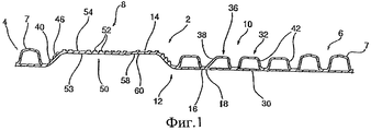
фиг.1 изображает частичный продольный разрез двустенного гофрированного трубчатого изделия с куполообразным соединителем и вставным соединителем до разрезания трубной секции на отрезки трубы,figure 1 depicts a partial longitudinal section of a double-walled corrugated tubular product with a domed connector and plug-in connector before cutting the pipe section into pipe sections,
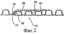
фиг.2 изображает частичный разрез, показывающий соединение двух отрезков трубы, выполненное с помощью вставного и куполообразного соединителей,figure 2 depicts a partial section showing the connection of two pipe sections made using plug-in and dome-shaped connectors,
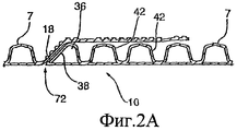
фиг.2А изображает частичный разрез соединения между куполообразным и вставным соединителями, причем гофры вставного соединителя имеют такой же диаметр, что и гофры трубы, а куполообразный соединитель имеет несколько больший диаметр,figa depicts a partial section of the connection between the domed and plug-in connectors, and the corrugations of the plug-in connector have the same diameter as the corrugations of the pipe, and the dome-shaped connector has a slightly larger diameter,
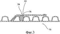
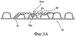
фиг.3 изображает частичный разрез вставного/куполообразного соединения и уплотнительного кольца, выполненного между передним гофром и промежуточным гофром вставного соединителя,figure 3 depicts a partial section of a plug-in / dome-shaped connection and a sealing ring made between the front corrugation and the intermediate corrugation of the plug-in connector,
фиг.3А изображает соединение куполообразного и вставного соединителей, причем вставной соединитель имеет уменьшенный диаметр и на поверхности одного из его гофров выполнено уплотнение,figa shows the connection of the domed and plug-in connectors, and the plug-in connector has a reduced diameter and a seal is made on the surface of one of its corrugations,
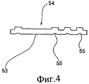
фиг.4 изображает частичный разрез, подробно показывающий наружную манжету куполообразного соединителя,4 is a partial sectional view showing in detail the outer cuff of the dome-shaped connector,
фиг.5 изображает ряд гофров различных форм,5 depicts a series of corrugations of various shapes,
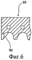
фиг.6 изображает частичный разрез формовочного блока, иллюстрирующий изменение указанного блока, обеспечивающее образование переходного сегмента, используемого для формирования вставного соединителя,6 is a partial sectional view of a molding block illustrating a variation of said block, enabling the formation of a transition segment used to form an insert connector,
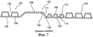
фиг.7 изображает частичный продольный разрез известной двустенной гофрированной трубы до разрезания указанной трубы на отрезки,Fig.7 depicts a partial longitudinal section of a known double-walled corrugated pipe before cutting the specified pipe into segments,
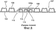
фиг.8 изображает частичный разрез известной трубы, приведенной на фиг.7, показывающий соединение двух отрезков трубы.Fig. 8 is a partial sectional view of the known pipe shown in Fig. 7, showing the connection of two pipe sections.
ОПИСАНИЕ ПРЕДПОЧТИТЕЛЬНЫХ ВАРИАНТОВ ВЫПОЛНЕНИЯDESCRIPTION OF PREFERRED EMBODIMENTS
На фиг.7 изображена известная конструкция стенки трубы, обозначенная в целом номером 101 позиции. Данная конструкция сформирована с использованием общего источника пластмассы, разделяемой на отдельные потоки, с помощью процесса экструзии, известного из уровня техники.7 shows a known construction of a pipe wall, indicated generally by 101 position numbers. This design is formed using a common source of plastic, divided into separate streams, using an extrusion process known from the prior art.
Указанная конструкция содержит внутреннюю стенку 103 трубы, сформированную из первого потока пластмассы, и наружную стенку 105 трубы, сформированную из второго потока пластмассы. Внутренняя стенка является гладкой, за исключением места, в котором она имеет изогнутую часть 109. Наружная стенка выполнена с рядом гофров, за исключением изогнутой части 109, в которой внутренняя и наружная стенка совпадают друг с другом.Said structure comprises an
Наружная стенка 105 выполнена с образованием гофров. Однако диаметр этих гофров изменяется по длине трубы. В частности, вдоль больших участков 107 длины трубы наружная стенка образует гофры 108, а вдоль малых участков 113 длины трубы указанная стенка образует гофры 114. Данные малые участки 113 также содержат изогнутую часть 109 стенки.The
Диаметр гофров 108 превышает диаметр гофров 114, причем гофры 114 имеют стенку большей толщины, поскольку оба вида гофров выполнены из одного и того же объема пластмассы.The diameter of the
Изогнутая часть 109 имеет переходную область 111, в которой она переходит в гофры 114 малого диаметра. В результате удаления этой переходной области, ограниченной положениями 130 и 132 реза, образуются две отдельные трубные секции. Одна секция содержит куполообразную часть 109а, полученную из изогнутой части 109 в результате удаления ее переходной области 111. В результате указанного удаления переходной области также образуется охватываемая концевая трубная конструкция 113, как показано на фиг.8, на котором охватываемый конец образован гофрами 114 малого диаметра. Как показано на фиг.8, в одном из углублений гофров 114 размещается уплотнение 115. Затем куполообразная часть 109а секции стенки трубы надвигается поверх гофров 114 концевой части стенки другой трубной секции, образующих охватываемый конец, как показано на фиг.8. В результате получается уплотненное соединение двух концов труб. Благодаря увеличенной толщине стенки гофров, образующих охватываемый конец, они приобретают прочность, обеспечивающую удерживание уплотнения в соединении.The
Несмотря на то что известная конфигурация, изображенная на фиг.7 и 8, является удовлетворительной для многих областей применения, зазор 119 образует зону прерывания, и внутренняя стенка 103 не является непрерывной. Кроме того, форму концевого гофра 114 трудно контролировать, поскольку он является первым гофром, выполненным после изогнутой части 109, присоединенной к нему с помощью переходной области 111. Последующие гофры 114 постепенно становятся более точными. Такая конфигурация не является наиболее предпочтительной, поскольку достижение уплотнения двух трубных секций усложняется.Although the known configuration shown in FIGS. 7 and 8 is satisfactory for many applications, the
На фиг.1 изображен непрерывный участок усовершенствованного отформованного трубного изделия 2, содержащего первую трубную секцию 3 и вторую трубную секцию 6, взаимно соединенные куполообразным соединителем 8, идущую в отходы или удаляемую секцию 12 и охватываемый вставной соединитель 10. Непрерывное отформованное трубное изделие разрезают по линии 14 реза и наклонной линии 16 реза для разделения указанного изделия на заданные отрезки трубы. Линия 16 выполнена в месте взаимного соединения внутренней и наружной стенок перед передним гофром 36 вставного соединителя. Данная конфигурация образует короткий концевой выступ 18.Figure 1 shows a continuous section of an improved molded
Вставной соединитель 10 имеет внутреннюю стенку 30 и наружную гофрированную стенку 32. Передний гофр 36 выполнен на свободном конце вставного соединителя и предпочтительно содержит два соответствующих промежуточных гофра 42.The plug-in
Передний гофр 36 имеет наклонную переднюю стенку 38, которая в целом соответствует наклонному переходному сегменту или стенке 46 куполообразного соединителя. Указанная стенка 46 переходит в наружную манжету 50 куполообразного соединителя. Манжета 50 имеет наружные ребра 52, выполненные в различных местоположениях по ее длине, а также неоребренную уплотнительную секцию 54, расположенную смежно с уплотнительным участком на вставном соединителе. По существу, секция 54 имеет внутреннюю стенку 53 с более равномерным диаметром, которая в меньшей степени подвержена возникновению неровностей 55 (см. фиг.4), чаще всего связанных с ребристым участком манжеты 50. Более подробно это показано на увеличенном разрезе, приведенном на фиг.4.The
Наружная манжета 50 куполообразного соединителя имеет свободный конец 58 со стенкой 60, которая расширяется в направлении наружу и обеспечивает направляющую часть для размещения вставного соединителя 10.The
Идущую в отходы или формообразующую переходную секцию 12 удаляют, однако при этом обеспечивается короткая формообразующая переходная часть между манжетой 50 куполообразного соединителя 8 и свободным концом вставного соединителя 10, содержащая концевой выступ 18 и переднюю стенку 38 переднего гофра 36.Waste or forming
Непрерывное отформованное трубное изделие, изображенное на фиг.1, разрезают на два отрезка трубы, при этом соединитель 10 одной трубы вставляют в соединитель 8 второй трубы. Передняя стенка 38 гофра 36 в целом соответствует переходной стенке 46 манжеты 50. Выступ 18 вставного соединителя взаимодействует с куполообразным соединителем у основания переходной стенки 46 и последнего гофра трубной секции. Как показано номером 72 позиции на фиг.2 и 2А, внутренние стенки соединенных труб являются по существу непрерывными, при этом отсутствует существенный зазор в месте присоединения выступа 18 и его примыкания к стенке 46. Предпочтительно отсутствует большой зазор между внутренней стенкой переднего гофра и внутренней стенкой трубы у начала куполообразного соединителя. При такой конфигурации достигаются улучшенные уплотнение и поток через две соединенные трубные секции.The continuous molded pipe product shown in FIG. 1 is cut into two pipe sections, with the
Изображенные на фиг.1 и 2 передний гофр 36 и соответствующие промежуточные гофры 42 имеют уменьшенный диаметр по сравнению с обычными гофрами 7 трубы. Манжета 50 имеет такой же диаметр, что и указанные гофры 7.Shown in figures 1 and 2, the
На фиг.2А изображено соединение, в котором диаметр и форма гофров вставного соединителя 10 в целом соответствуют диаметру и форме обычных гофров 7, за исключением того, что вставной соединитель имеет специальный передний гофр 36, предназначенный для взаимодействия с переходной стенкой 46 куполообразного соединителя. Диаметр манжеты 50 слегка увеличен по сравнению с максимальным диаметром промежуточных гофров труб.On figa shows a connection in which the diameter and shape of the corrugations of the plug-in
Между передним гофром 36 и первым промежуточным гофром, следующим за передним гофром, предпочтительно вставлено уплотнительное кольцо, как показано в целом на фиг.3А. Уплотнительное кольцо 76 туго посажено на наружные стенки переднего гофра 36 и первого промежуточного гофра вставного соединителя и, кроме того, взаимодействует с внутренней стенкой неоребренной уплотнительной секции 54 манжеты 50. Данная внутренняя стенка является в целом непрерывной и менее подвержена деформации, благодаря чему обеспечивается лучшее уплотнение. Дополнительные ребра на переходной стенке 46 и на манжете 50 обеспечивают дополнительную прочность и жесткость. В месте расположения уплотнения данные ребра отсутствуют.Between the
Длина передней стенки переднего гофра превышает длину передней стенки последующих гофров. Предпочтительно передняя стенка 38 расположена под углом приблизительно 45°, тогда как передняя стенка других гофров является более крутой для обеспечения дополнительной жесткости. Например, на фиг.3 первый промежуточный гофр 80 деформирован на верхней поверхности и снабжен уплотнительным кольцом 76а, которое установлено в полученном углублении указанного гофра. Наружная манжета 50 куполообразного соединителя имеет неоребренный участок 54а, расположенный с обеспечением взаимодействия с кольцом 76а. Это обеспечивает более надежное уплотнение вставного соединителя с куполообразным соединителем. Как показано на чертежах, выступ 18 по существу примыкает к внутренней стенке первой трубы. Как изложено выше, это обеспечивает улучшение потока через соединенные трубы, а также снижает протечку.The length of the front wall of the front corrugation exceeds the length of the front wall of the subsequent corrugations. Preferably, the
На фиг.4 изображены элементы оребрения наружной манжеты и, в частности, проиллюстрировано наличие более гладкой неоребренной внутренней стенки на участке 54. По существу, формирование ребер требует приложения всасывающего усилия к пластмассе для втягивания ребер в формовочный блок. В результате этого на внутренней стенке образуется или формируется небольшая деформация. При наличии неоребренного уплотнительного участка 54 внутренняя стенка в области уплотнения является гладкой и достигается более надежное уплотнение.Figure 4 shows the elements of the ribbing of the outer cuff and, in particular, illustrates the presence of a smoother, non-ribbed inner wall in
На фиг.5 изображен разрез ряда различных гофров 89, иллюстрирующий возможность использования различных форм гофров как трубы, так и вставного соединителя.Figure 5 shows a section of a number of
На фиг.6 изображен частичный вид формовочного блока 89 с вкладышем 90, используемым для формирования переходной стенки куполообразного соединителя. Вкладыш аналогичного типа может использоваться для формирования переднего гофра вставного соединителя. Такие вкладыши обеспечивают возможность экономически эффективной модификации существующих или широко распространенных фасонных формовочных блоков.Figure 6 shows a partial view of the
Несмотря на то что в данном описании подробно описаны предпочтительные варианты выполнения изобретения, специалистам в данной области техники должно быть понятно, что возможно выполнение изменений указанных вариантов без отклонения от данного изобретения или объема прилагаемой формулы изобретения.Although the preferred embodiments of the invention are described in detail herein, those skilled in the art will appreciate that it is possible to make changes to these options without departing from the present invention or the scope of the appended claims.
Claims (14)
при этом указанный куполообразный соединитель имеет переходную стенку, проходящую от места взаимного соединения внутренней и наружной стенок трубы к наружной манжете, размер которой обеспечивает размещение указанного вставного соединителя,
при этом указанный ряд гофров вставного соединителя содержит передний гофр и по меньшей мере последующий гофр, причем указанный передний гофр расположен на свободном конце указанного соединителя и его передняя стенка наклонена с обеспечением взаимодействия и соединения с переходным сегментом куполообразного соединителя трубы, имеющей аналогичную конфигурацию, при введении в него,
при этом указанные передняя стенка и переходной сегмент куполообразного соединителя имеют большую длину и меньший угол наклона по сравнению с передней стенкой указанного по меньшей мере одного последующего гофра,
при этом внутренняя стенка вставного соединителя на его свободном конце выступает в направлении продольной оси концевой части трубы за передний гофр с образованием концевой части, действующей в качестве соединительного перехода внутренних стенок между двумя трубами, соединенными с помощью вставного соединителя одной трубы, вставленного в куполообразный соединитель второй трубы.1. A corrugated plastic pipe with a double-walled structure having a continuous inner wall restricting a uniform passage through the specified pipe and an outer wall forming corrugations attached to the inner wall at the inner edge of each corrugation, with a dome-shaped connector made at one end of the pipe, and the opposite end is a plug-in connector having a number of corrugations and an inner wall corresponding to the inner wall of the pipe,
wherein said dome-shaped connector has a transition wall extending from the place of mutual connection of the inner and outer walls of the pipe to the outer cuff, the size of which ensures the placement of the specified plug-in connector,
wherein said row of corrugations of the plug-in connector comprises a front corrugation and at least a subsequent corrugation, said front corrugation being located at the free end of said connector and its front wall is inclined to allow interaction and connection with the transition segment of the domed pipe connector having a similar configuration when introduced into him
wherein said front wall and the transitional segment of the dome-shaped connector have a greater length and a smaller angle of inclination compared with the front wall of the specified at least one subsequent corrugation,
the inner wall of the plug-in connector at its free end protrudes in the direction of the longitudinal axis of the pipe end portion beyond the front corrugation to form an end portion acting as a connecting transition of the inner walls between two pipes connected by a plug-in connector of one pipe inserted into the dome-shaped connector of the second pipes.
Applications Claiming Priority (3)
| Application Number | Priority Date | Filing Date | Title |
|---|---|---|---|
| CA2,621,322 | 2008-02-14 | ||
| CA2621322A CA2621322C (en) | 2008-02-14 | 2008-02-14 | Double walled corrugated pipe section with pipe coupling |
| PCT/CA2009/000143 WO2009100522A1 (en) | 2008-02-14 | 2009-02-06 | Double wall corrugated pipe section with pipe coupling |
Publications (2)
| Publication Number | Publication Date |
|---|---|
| RU2010133720A RU2010133720A (en) | 2012-03-20 |
| RU2474747C2 true RU2474747C2 (en) | 2013-02-10 |
Family
ID=40677887
Family Applications (1)
| Application Number | Title | Priority Date | Filing Date |
|---|---|---|---|
| RU2010133720/06A RU2474747C2 (en) | 2008-02-14 | 2009-02-06 | Double-wall corrugated pipe section with pipe connection |
Country Status (12)
| Country | Link |
|---|---|
| US (1) | US20090206595A1 (en) |
| EP (1) | EP2090817B1 (en) |
| JP (1) | JP5368483B2 (en) |
| CN (1) | CN101952632B (en) |
| AT (1) | ATE542082T1 (en) |
| AU (1) | AU2009214769B2 (en) |
| BR (1) | BRPI0908865A2 (en) |
| CA (1) | CA2621322C (en) |
| ES (1) | ES2381063T3 (en) |
| PL (1) | PL2090817T3 (en) |
| RU (1) | RU2474747C2 (en) |
| WO (1) | WO2009100522A1 (en) |
Families Citing this family (3)
| Publication number | Priority date | Publication date | Assignee | Title |
|---|---|---|---|---|
| DE102011007744A1 (en) * | 2011-04-20 | 2012-10-25 | Mahle International Gmbh | Hollow body with connection piece |
| WO2019014746A1 (en) * | 2017-07-20 | 2019-01-24 | Lupke Manfred Arno Alfred | Coilable pipe with minimally angled corrugations |
| CN114719112A (en) * | 2022-03-31 | 2022-07-08 | 公元股份有限公司 | Bellmouth structure of corrugated pipe |
Citations (6)
| Publication number | Priority date | Publication date | Assignee | Title |
|---|---|---|---|---|
| US5335945A (en) * | 1992-07-14 | 1994-08-09 | Tuf-Tite, Inc. | Flexible pipe connector |
| RU2030674C1 (en) * | 1992-06-10 | 1995-03-10 | Дмитрий Сергеевич Тукнов | Flexible pipe and method of pipeline construction |
| US5996635A (en) * | 1996-02-07 | 1999-12-07 | Hegler; Ralph Peter | Composite pipe with a socket and method for its manufacture |
| CA2342360A1 (en) * | 1998-11-23 | 2000-06-02 | Manfred A. A. Lupke | Pipe with coupling conforming to pipe diameter |
| US6941972B2 (en) * | 2002-07-25 | 2005-09-13 | Hancor, Inc. | Corrugated pipe |
| WO2005098302A1 (en) * | 2004-04-08 | 2005-10-20 | Lupke Manfred Arno Alfred | Method of forming corrugated pipe with a pipe spigot seal seat |
Family Cites Families (12)
| Publication number | Priority date | Publication date | Assignee | Title |
|---|---|---|---|---|
| US1049542A (en) * | 1912-04-09 | 1913-01-07 | Smith Metal Perforating Company | Corrugated metal casing for culverts, drainage-tiling, &c. |
| JPS6062930U (en) * | 1983-10-05 | 1985-05-02 | タキロン株式会社 | double wall tube |
| US4747621A (en) * | 1986-11-19 | 1988-05-31 | Action Technology | Aquatic vacuum hose swivel cuff |
| DE3921075A1 (en) * | 1989-06-28 | 1991-01-03 | Wilhelm Hegler | PLASTIC TUBE FOR PIPE RENOVATION |
| US5326138A (en) * | 1992-10-16 | 1994-07-05 | Hancor, Inc. | High pressure coupling for plastic pipe and conduit |
| US6126209A (en) * | 1999-01-08 | 2000-10-03 | Advanced Drainage Systems, Inc | Pipe having an in-line bell |
| EP1217282A1 (en) * | 2000-12-22 | 2002-06-26 | Plasticos IMA, S.A. | Improved thermoplastic pipe |
| DE50104198D1 (en) * | 2001-02-09 | 2004-11-25 | Hegler Ralph Peter | A pipe assembly |
| DE20205625U1 (en) * | 2002-04-11 | 2002-06-20 | Lupke Manfred Arno Alfred | Multi-layer corrugated plastic pipe with fins, preliminary product and device for their production |
| DE10328626A1 (en) * | 2003-06-26 | 2005-01-13 | Hegler, Ralph-Peter, Dr.-Ing. | A pipe assembly |
| ATE372205T1 (en) * | 2004-07-03 | 2007-09-15 | Hegler Ralph Peter Dr Ing | METHOD FOR THE CONTINUOUS PRODUCTION OF A DOUBLE-WALL CORRUGATED PIPE WITH A PIPE SLEEVE, THE DOUBLE-WALL CORRUGATED PIPE AND THE DEVICE FOR IMPLEMENTING THE METHOD |
| US7434850B2 (en) * | 2005-09-30 | 2008-10-14 | Prinsco, Inc. | Fluid-tight coupling system for corrugated pipe |
-
2008
- 2008-02-14 CA CA2621322A patent/CA2621322C/en active Active
-
2009
- 2009-02-06 BR BRPI0908865A patent/BRPI0908865A2/en not_active IP Right Cessation
- 2009-02-06 WO PCT/CA2009/000143 patent/WO2009100522A1/en active Application Filing
- 2009-02-06 CN CN2009801053658A patent/CN101952632B/en active Active
- 2009-02-06 JP JP2010546188A patent/JP5368483B2/en not_active Expired - Fee Related
- 2009-02-06 AU AU2009214769A patent/AU2009214769B2/en not_active Ceased
- 2009-02-06 RU RU2010133720/06A patent/RU2474747C2/en active
- 2009-02-10 US US12/320,947 patent/US20090206595A1/en not_active Abandoned
- 2009-02-12 PL PL09152692T patent/PL2090817T3/en unknown
- 2009-02-12 AT AT09152692T patent/ATE542082T1/en active
- 2009-02-12 ES ES09152692T patent/ES2381063T3/en active Active
- 2009-02-12 EP EP09152692A patent/EP2090817B1/en active Active
Patent Citations (6)
| Publication number | Priority date | Publication date | Assignee | Title |
|---|---|---|---|---|
| RU2030674C1 (en) * | 1992-06-10 | 1995-03-10 | Дмитрий Сергеевич Тукнов | Flexible pipe and method of pipeline construction |
| US5335945A (en) * | 1992-07-14 | 1994-08-09 | Tuf-Tite, Inc. | Flexible pipe connector |
| US5996635A (en) * | 1996-02-07 | 1999-12-07 | Hegler; Ralph Peter | Composite pipe with a socket and method for its manufacture |
| CA2342360A1 (en) * | 1998-11-23 | 2000-06-02 | Manfred A. A. Lupke | Pipe with coupling conforming to pipe diameter |
| US6941972B2 (en) * | 2002-07-25 | 2005-09-13 | Hancor, Inc. | Corrugated pipe |
| WO2005098302A1 (en) * | 2004-04-08 | 2005-10-20 | Lupke Manfred Arno Alfred | Method of forming corrugated pipe with a pipe spigot seal seat |
Also Published As
| Publication number | Publication date |
|---|---|
| CN101952632B (en) | 2012-08-22 |
| JP5368483B2 (en) | 2013-12-18 |
| PL2090817T3 (en) | 2012-05-31 |
| CA2621322A1 (en) | 2009-08-14 |
| WO2009100522A1 (en) | 2009-08-20 |
| EP2090817B1 (en) | 2012-01-18 |
| AU2009214769A1 (en) | 2009-08-20 |
| ATE542082T1 (en) | 2012-02-15 |
| EP2090817A2 (en) | 2009-08-19 |
| ES2381063T3 (en) | 2012-05-22 |
| CN101952632A (en) | 2011-01-19 |
| RU2010133720A (en) | 2012-03-20 |
| EP2090817A3 (en) | 2010-04-28 |
| JP2011511914A (en) | 2011-04-14 |
| BRPI0908865A2 (en) | 2015-11-24 |
| CA2621322C (en) | 2014-12-16 |
| AU2009214769B2 (en) | 2013-06-27 |
| US20090206595A1 (en) | 2009-08-20 |
Similar Documents
| Publication | Publication Date | Title |
|---|---|---|
| CA2743807C (en) | Three-wall corrugated pipe couplings and methods | |
| US8820800B2 (en) | Multi-wall corrugated pipe couplings and methods | |
| KR100486948B1 (en) | Culvert | |
| RU2474747C2 (en) | Double-wall corrugated pipe section with pipe connection | |
| CN107532761B (en) | Two-stage coupling for corrugated tubing | |
| CN1582374A (en) | Pipe having a water-tight in-line bell | |
| RU2003109649A (en) | BUTT JOINT BETWEEN TWO SECTIONS OF SHEET METAL PIPES AND METHOD FOR ITS MANUFACTURE | |
| JP2018513317A (en) | Method for forming an in-line triple wall coupling connector | |
| KR102036168B1 (en) | double walled pipe for a sewer pipeline and method of manufacturing the pipe | |
| US20030090112A1 (en) | Pipe joint assembly | |
| JP6010437B2 (en) | Existing strip rehabilitation strip | |
| CN211574432U (en) | Outer polygon reinforcing corrugated pipe | |
| CN110906065A (en) | Outer polygonal reinforced corrugated pipe and forming process thereof | |
| CN107477266A (en) | Double-wall corrugated pipe | |
| JP6267585B2 (en) | Pipe making components | |
| RU2256115C2 (en) | Joining member | |
| JP2006322491A (en) | Synthetic resin pipe body | |
| KR102569472B1 (en) | Waterway for Composite Connection of Straight and Curved Sections | |
| JP5256057B2 (en) | Synthetic resin propelling tube | |
| JPH0727262A (en) | Corrugated tube | |
| WO2016141452A1 (en) | Two stage coupling for corrugated pipe | |
| JPH0730670B2 (en) | Connection structure of buried pipe for propulsion method |