EP2090797A2 - Control method for a vehicle clutch - Google Patents
Control method for a vehicle clutch Download PDFInfo
- Publication number
- EP2090797A2 EP2090797A2 EP09150927A EP09150927A EP2090797A2 EP 2090797 A2 EP2090797 A2 EP 2090797A2 EP 09150927 A EP09150927 A EP 09150927A EP 09150927 A EP09150927 A EP 09150927A EP 2090797 A2 EP2090797 A2 EP 2090797A2
- Authority
- EP
- European Patent Office
- Prior art keywords
- clutch
- signal
- pressure
- actual
- control unit
- Prior art date
- Legal status (The legal status is an assumption and is not a legal conclusion. Google has not performed a legal analysis and makes no representation as to the accuracy of the status listed.)
- Granted
Links
Images
Classifications
-
- F—MECHANICAL ENGINEERING; LIGHTING; HEATING; WEAPONS; BLASTING
- F16—ENGINEERING ELEMENTS AND UNITS; GENERAL MEASURES FOR PRODUCING AND MAINTAINING EFFECTIVE FUNCTIONING OF MACHINES OR INSTALLATIONS; THERMAL INSULATION IN GENERAL
- F16D—COUPLINGS FOR TRANSMITTING ROTATION; CLUTCHES; BRAKES
- F16D48/00—External control of clutches
- F16D48/06—Control by electric or electronic means, e.g. of fluid pressure
- F16D48/066—Control of fluid pressure, e.g. using an accumulator
-
- F—MECHANICAL ENGINEERING; LIGHTING; HEATING; WEAPONS; BLASTING
- F16—ENGINEERING ELEMENTS AND UNITS; GENERAL MEASURES FOR PRODUCING AND MAINTAINING EFFECTIVE FUNCTIONING OF MACHINES OR INSTALLATIONS; THERMAL INSULATION IN GENERAL
- F16D—COUPLINGS FOR TRANSMITTING ROTATION; CLUTCHES; BRAKES
- F16D2500/00—External control of clutches by electric or electronic means
- F16D2500/10—System to be controlled
- F16D2500/102—Actuator
- F16D2500/1026—Hydraulic
-
- F—MECHANICAL ENGINEERING; LIGHTING; HEATING; WEAPONS; BLASTING
- F16—ENGINEERING ELEMENTS AND UNITS; GENERAL MEASURES FOR PRODUCING AND MAINTAINING EFFECTIVE FUNCTIONING OF MACHINES OR INSTALLATIONS; THERMAL INSULATION IN GENERAL
- F16D—COUPLINGS FOR TRANSMITTING ROTATION; CLUTCHES; BRAKES
- F16D2500/00—External control of clutches by electric or electronic means
- F16D2500/10—System to be controlled
- F16D2500/108—Gear
- F16D2500/1086—Concentric shafts
-
- F—MECHANICAL ENGINEERING; LIGHTING; HEATING; WEAPONS; BLASTING
- F16—ENGINEERING ELEMENTS AND UNITS; GENERAL MEASURES FOR PRODUCING AND MAINTAINING EFFECTIVE FUNCTIONING OF MACHINES OR INSTALLATIONS; THERMAL INSULATION IN GENERAL
- F16D—COUPLINGS FOR TRANSMITTING ROTATION; CLUTCHES; BRAKES
- F16D2500/00—External control of clutches by electric or electronic means
- F16D2500/30—Signal inputs
- F16D2500/302—Signal inputs from the actuator
- F16D2500/3024—Pressure
-
- F—MECHANICAL ENGINEERING; LIGHTING; HEATING; WEAPONS; BLASTING
- F16—ENGINEERING ELEMENTS AND UNITS; GENERAL MEASURES FOR PRODUCING AND MAINTAINING EFFECTIVE FUNCTIONING OF MACHINES OR INSTALLATIONS; THERMAL INSULATION IN GENERAL
- F16D—COUPLINGS FOR TRANSMITTING ROTATION; CLUTCHES; BRAKES
- F16D2500/00—External control of clutches by electric or electronic means
- F16D2500/30—Signal inputs
- F16D2500/304—Signal inputs from the clutch
- F16D2500/30404—Clutch temperature
-
- F—MECHANICAL ENGINEERING; LIGHTING; HEATING; WEAPONS; BLASTING
- F16—ENGINEERING ELEMENTS AND UNITS; GENERAL MEASURES FOR PRODUCING AND MAINTAINING EFFECTIVE FUNCTIONING OF MACHINES OR INSTALLATIONS; THERMAL INSULATION IN GENERAL
- F16D—COUPLINGS FOR TRANSMITTING ROTATION; CLUTCHES; BRAKES
- F16D2500/00—External control of clutches by electric or electronic means
- F16D2500/30—Signal inputs
- F16D2500/316—Other signal inputs not covered by the groups above
- F16D2500/3168—Temperature detection of any component of the control system
-
- F—MECHANICAL ENGINEERING; LIGHTING; HEATING; WEAPONS; BLASTING
- F16—ENGINEERING ELEMENTS AND UNITS; GENERAL MEASURES FOR PRODUCING AND MAINTAINING EFFECTIVE FUNCTIONING OF MACHINES OR INSTALLATIONS; THERMAL INSULATION IN GENERAL
- F16D—COUPLINGS FOR TRANSMITTING ROTATION; CLUTCHES; BRAKES
- F16D2500/00—External control of clutches by electric or electronic means
- F16D2500/50—Problem to be solved by the control system
- F16D2500/506—Relating the transmission
- F16D2500/5063—Shaft dither, i.e. applying a pulsating torque to a (transmission) shaft to create a buzz or dither, e.g. to prevent tooth butting or gear locking
-
- F—MECHANICAL ENGINEERING; LIGHTING; HEATING; WEAPONS; BLASTING
- F16—ENGINEERING ELEMENTS AND UNITS; GENERAL MEASURES FOR PRODUCING AND MAINTAINING EFFECTIVE FUNCTIONING OF MACHINES OR INSTALLATIONS; THERMAL INSULATION IN GENERAL
- F16D—COUPLINGS FOR TRANSMITTING ROTATION; CLUTCHES; BRAKES
- F16D2500/00—External control of clutches by electric or electronic means
- F16D2500/70—Details about the implementation of the control system
- F16D2500/704—Output parameters from the control unit; Target parameters to be controlled
- F16D2500/70402—Actuator parameters
- F16D2500/70406—Pressure
-
- F—MECHANICAL ENGINEERING; LIGHTING; HEATING; WEAPONS; BLASTING
- F16—ENGINEERING ELEMENTS AND UNITS; GENERAL MEASURES FOR PRODUCING AND MAINTAINING EFFECTIVE FUNCTIONING OF MACHINES OR INSTALLATIONS; THERMAL INSULATION IN GENERAL
- F16D—COUPLINGS FOR TRANSMITTING ROTATION; CLUTCHES; BRAKES
- F16D2500/00—External control of clutches by electric or electronic means
- F16D2500/70—Details about the implementation of the control system
- F16D2500/706—Strategy of control
- F16D2500/70668—Signal filtering
Definitions
- the present invention relates to a method for driving a clutch of a vehicle drive train, in particular a vehicle drive train with a dual-clutch transmission.
- Dual clutch transmissions are well known. They include a dual-clutch arrangement with two parallel friction clutches and a stepped transmission with two parallel partial transmissions. A branch with a first friction clutch and a first partial transmission, the odd gear ratios are assigned. The other branch with the second friction clutch and the second partial transmission, the even gears are assigned. On the input side, the friction clutches are connected to a drive motor, for example an internal combustion engine, a hybrid drive unit or the like.
- the partial transmissions are usually realized as a spur gear.
- the compound of the friction clutch assembly with the partial transmissions via a shaft assembly having an inner shaft and a concentrically arranged thereto hollow shaft.
- gear changes can be performed without interruption of traction.
- the operation of the friction clutches is automated.
- the actuators used for this purpose must be precisely controlled in particular in the transfer of the drive torque from one friction clutch to the other friction clutch to ensure a smooth gear change.
- a method for driving a clutch of a vehicle drive train wherein a controller of an electronic control unit generates a desired electric signal corresponding to a target pressure to be applied to the clutch, wherein the control unit of a Sensor receives an electrical actual signal, which is to correspond to an actual pressure, with which the clutch is acted upon, wherein the sensor measures the pressure at a measuring location, which is connected via a transmission path to a loading location, to which the clutch is subjected to a clutch pressure, and wherein the actual signal passes through a transmission element with a delay characteristic before it is fed to the controller.
- the inventive measure the first supply signal to a transmission element with a delay characteristic before it is fed to the controller, this problem can be eliminated. In this way, in particular, a larger control difference between the desired value and the respective actual value can be achieved.
- the controller can work better hereby.
- delay property is to be understood broadly in the present case. A delay should accordingly be achieved with a pure delay element become. To the same extent, however, this delay property can also be reduced by a transmission element which, for example, simulates a PT1 function (PT1 element).
- the delay characteristic of the transmission element is a function of the temperature.
- the extent of the delay at higher temperatures is preferably set smaller, since the system is then more in a steady state and can work more precisely anyway.
- the temperature may be, for example, the temperature of a fluid, such as an oil, with which the clutch is driven. Alternatively, the temperature may also be the temperature of an electric actuator motor or an associated power stage. However, the temperature is preferably a temperature which is related to the temperature of the coupling itself, preferably in a proportional relationship.
- the delay characteristic of the transmission element is a function of the desired pressure.
- the degree of delay of the transmission element is set correspondingly smaller, since in this case the controller receives a relatively high control difference anyway.
- the coupling is fluidically, in particular hydraulically actuated and when the actual signal is a pressure signal of a pressure sensor.
- the coupling is actuated electromechanically or electromagnetically, wherein the actual signal is a current signal of an electric current sensor.
- a hydraulic actuator In a hydraulic actuator, the influence of a hydraulic transmission path can be particularly large, so that the invention has particular advantages. Even with an electric actuator, however, a transmission path between the measuring location and the application site can be present, which can be compensated by the method according to the invention.
- the above object is achieved by a method for driving a clutch of a vehicle drive train, wherein an electronic control unit generates a target electric signal corresponding to a target pressure to be applied to the clutch, the control unit being controlled by a sensor receives an electrical actual signal, which is to correspond to an actual pressure, with which the clutch is acted upon, and wherein the desired signal is modulated with a higher-frequency signal (dither) to minimize hysteresis effects.
- the method according to the invention is applicable in particular during the filling phase.
- the method according to the invention can also be used in other phases of the coupling control.
- the desired signal is modulated with the higher-frequency signal at least during a section of the filling phase.
- the modulation of the desired signal is preferably terminated a certain time before the predicted reaching of the engagement point at which the torque transmission exceeds a certain level.
- the setpoint signal is generated by the control unit during a filling phase of the clutch, starting from an open basic state of the clutch in the direction of an engagement point of the clutch first in the form of an unregulated, ie controlled signal and then in the form of a controlled signal depending on an actual value ,
- the filling phase first by an unregulated, i.
- an unregulated i.
- the unregulated signal is an excessive signal.
- An excessive signal is understood to be a signal which is controlled such that it lies at least in sections above the desired target value for reaching the point of engagement of the clutch.
- the overdriven controlled signal may be given a PDTI characteristic, that is, initially a high peak and then a falling curve.
- the falling curve can be similar to a PT1 member or similar to a PI function.
- the actual control of the signal in the subsequent phase can be done for example via a PI controller.
- the clutch may be a dry clutch, but is preferably a wet-running clutch such as a wet-running multi-plate clutch.
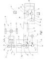
- Fig. 1 is a motor vehicle such as a passenger car generally designated 10.
- the motor vehicle 10 has a drive train 12 with a drive motor 14.
- the drive motor 14 may be, for example, an internal combustion engine or a hybrid drive unit.
- the drive train 12 also has a friction clutch 16, which is shown here as a single clutch in the form of a starting clutch.
- the drive train 12 has a stepped transmission 18, for example in the form of a spur or countershaft transmission.
- the output of the stepped transmission 18 is connected to a transaxle 20, which distributes the driving force to driven wheels 22L, 22R of the motor vehicle 10.
- a hydraulic actuation by means of a hydraulic actuator 24 This usually has a piston, the clutch via a hydraulic fluid (for example ATF- ⁇ 1) presses, with a force F K , which is proportional to a clutch pressure P K.
- the hydraulic actuator 24 is controlled via a hydraulic circuit 26. Furthermore, the motor vehicle 10 has an electrical control unit 30, by means of which the hydraulic circuit 26 can be controlled.
- the electrical control unit 30 has a control device 32, for example in the form of a microcontroller and a controller 34.
- the controller 34 may be part of the control device 32 or may be provided as a separate component within the control unit 30.
- the control unit 30 includes a digital / analog converter 36, which converts digital control signals of the controller 34 into analog signals which are supplied to the hydraulic circuit 26.
- the hydraulic circuit 26 has a fluid pump 40, which generates a line pressure P L in conjunction with a pressure regulating valve.
- the fluid is sucked in from an unspecified tank.
- the pump 40 may then be driven, for example, by means of an electric motor 42 (or as an accessory via the crankshaft of the drive motor 14).
- the fluid provided by the pump 40 may be used to cool the friction clutch 16. For reasons of clarity, these lines are not shown.
- the hydraulic circuit 26 also has a pressure regulating valve (in particular pressure reducing valve) 44, which generates a regulated pressure P R for the control of the hydraulic actuator 24 from the line pressure P L.
- the regulated pressure P R is provided to the actuator 24 via a hydraulic transmission path 46 (for example, a rotary union, hydraulic lines, etc.).
- the hydraulic circuit 26 includes a pressure sensor 48 provided in association with the pressure regulating valve 44.
- the hydraulic transmission path 46 is arranged between the pressure sensor 48 and the actuator 24.
- the control unit 30 further comprises a transmission member 50, with which a signal from the pressure sensor 48 is subjected to a delay or damping before this signal is supplied to the controller 34.
- the transmission member 50 may be part of the control device 32, so be simulated by software.
- the control device 32 generates a signal for a desired pressure 58 on the basis of superordinate control parameters. This signal is fed to the controller 34.
- the controller 34 generates a digital command signal 60, which is converted in the digital / analog converter 36 into an analog command signal 62.
- the analog target signal 62 is supplied to the pressure control valve 44 and controls the regulated pressure P R.
- the pressure sensor 48 generates an actual signal 64 (P actual ) which is input to the transmission member 50.
- P actual an actual signal 64
- the actual signal 64 experiences a delay or damping.
- the corrected in this way actual signal 66 is supplied to the controller 34.
- control unit 30 may also be configured to provide a motor control signal 67 for the electric motor 42. Also is in Fig. 1 that the controller 32 sets the delay characteristic of the transmission member 50 in accordance with the temperature (temperature setting signal 68). Alternatively or cumulatively, the deceleration property of the transmission member 50 may also be adjusted depending on the respective generated desired pressure 58 (shown by a target pressure adjustment signal 69).
- the transmission member 50 can be generally used in the context of driving the friction clutch 16. Preferably, however, it is used when the clutch 16 is filled, that is, is shifted from an open state to a state in which the point of engagement of the clutch is reached. In other cases, the transmission member 50 may also be bypassed if necessary.
- an exact control difference between the target pressure and the actual pressure in the clutch piston chamber based on the measured signal 64 can be calculated .. This allows the controller to work better. At higher temperatures, the deceleration property tends to be reduced. Correspondingly, at higher target pressures (and / or at higher actual pressures after the delay element 66), the deceleration property can also be reduced.
- an electric actuator can be used instead of a hydraulic actuator 24, instead of a hydraulic circuit 26, an electric or electronic circuit would be used, by means of which the corresponding drive signals for the electric actuator are generated.
- an electrical transmission path (corresponding to the transmission path 46) can lie between the value of a then usually occurring electric current measurement (corresponding to the pressure sensor 48) and the location at which the electric current is finally used due to the electric actuator 24.
- a transmission member 50 of the type described above can be used.
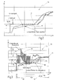
- a diagram 70 is shown, in which the filling operation is initiated by an increase of the desired pressure by means of a jump signal.
- the filling phase essentially ends at a point in time 71.
- the diagram 70 furthermore represents the actual signal 64 generated by the pressure sensor 48 (sensor signal). Further, in the graph 70, the corrected actual pressure 66 detected by the transmission member 50 is shown ("estimated clutch pressure").
- the transmission element 50 With its delay or damping characteristic, virtually forms the transmission path 46.
- the transmission member 50 thus fulfills the function of a pressure observer, by which the actual pressure in the actuator 24 is estimated. Because through the transmission path 46 of the present at a certain time in the region of the measuring location of the sensor 48 regulated pressure P R only a certain time later in the hydraulic actuator 24 as a clutch pressure P K "arrive". Through this dynamic influence of pressure by the transmission path 46 corresponds to the temperature measured by the sensor 48 the actual pressure P is not the actual pressure P K in the actuator 24 through the transmission member 50, this can be compensated for.
- the transmission member 50 having a deceleration characteristic which is a function of the temperature and / or the target pressure (arrows 68, 69), the dynamic behavior of the transmission link 46 can be more realistically estimated and thus compensated.
- a diagram 72 is shown, which in terms of the general sequence of the diagram 70 of Fig. 2 equivalent.
- a setpoint signal (manipulated variable with pressure generator) 60 is generated, which is modulated with a high-frequency signal having a modulation amplitude 74.
- a "dither" signal is superimposed on the desired signal.
- the filling phase of the coupling 16 is in Fig. 3 at 76 and lasts from raising the set pressure to reaching the point of engagement (at 71).
- the modulation of the desired signal 60 takes place in a modulation phase 78, which ends clearly before the engagement point 71.
- the modulation is exerted only in a "soft" region of the clutch, so that no influences on the drive train can be exercised (in particular no transmission of vibrations to the drive train).
- the filling phase 76 in the driving method of FIG Fig. 3 divided into a control phase 80 and a control phase 82.
- the setpoint signal 60 is not regulated by way of feedback but is predetermined in a controlled manner.
- the signal can have, for example, the characteristic of a PDT1 function.
- the setpoint signal 60 at the beginning of the control phase 80 receives a relatively high peak value, which is significantly above the setpoint pressure. Proceeding from this, the signal can then drop slightly again, for example in the manner of a PT1 element or a PI element.
- the control phase 80 likewise ends clearly before the point of engagement is reached, in particular even before the modulation phase 78 has ended.
- a control process is carried out in the controller 34 using the actual signal 64 (or the corrected actual signal 66).
- the modulation amplitude 74 can be significantly reduced.
- the system can be impressed by the controlled desired signal 60, a relatively rapid increase of the corresponding pressure values (the regulated pressure P R and consequently also the clutch pressure P K ).
- the subsequent control phase 82 an exact positioning or device of the clutch 16 for the engagement point 71 can take place.
Landscapes
- Physics & Mathematics (AREA)
- Fluid Mechanics (AREA)
- Engineering & Computer Science (AREA)
- General Engineering & Computer Science (AREA)
- Mechanical Engineering (AREA)
- Hydraulic Clutches, Magnetic Clutches, Fluid Clutches, And Fluid Joints (AREA)
Abstract
Description
Die vorliegende Erfindung betrifft ein Verfahren zum Ansteuern einer Kupplung eines Fahrzeugantriebsstranges, insbesondere eines Fahrzeugantriebsstranges mit einem Doppelkupplungsgetriebe.The present invention relates to a method for driving a clutch of a vehicle drive train, in particular a vehicle drive train with a dual-clutch transmission.
Doppelkupplungsgetriebe sind allgemein bekannt. Sie beinhalten eine Doppelkupplungsanordnung mit zwei parallelen Reibkupplungen und ein Stufengetriebe mit zwei parallelen Teilgetrieben. Einem Zweig mit einer ersten Reibkupplung und einem ersten Teilgetriebe sind die ungeraden Gangstufen zugeordnet. Dem anderen Zweig mit der zweiten Reibkupplung und dem zweiten Teilgetriebe sind die geraden Gangstufen zugeordnet. Eingangsseitig sind die Reibkupplungen mit einem Antriebsmotor verbunden, beispielsweise einem Verbrennungsmotor, einer Hybridantriebseinheit oder ähnliches. Die Teilgetriebe sind in der Regel als Stirnradgetriebe realisiert. Die Verbindung der Reibkupplungsanordnung mit dem Teilgetrieben erfolgt über eine Wellenanordnung mit einer Innenwelle und einer konzentrisch hierzu angeordneten Hohlwelle.Dual clutch transmissions are well known. They include a dual-clutch arrangement with two parallel friction clutches and a stepped transmission with two parallel partial transmissions. A branch with a first friction clutch and a first partial transmission, the odd gear ratios are assigned. The other branch with the second friction clutch and the second partial transmission, the even gears are assigned. On the input side, the friction clutches are connected to a drive motor, for example an internal combustion engine, a hybrid drive unit or the like. The partial transmissions are usually realized as a spur gear. The compound of the friction clutch assembly with the partial transmissions via a shaft assembly having an inner shaft and a concentrically arranged thereto hollow shaft.
Durch überschneidende Betätigung der zwei Reibkupplungen können Gangwechsel ohne Zugkraftunterbrechung durchgeführt werden. Die Betätigung der Reibkupplungen erfolgt automatisiert. Die hierzu verwendeten Aktuatoren müssen dabei insbesondere bei der Übergabe des Antriebsmomentes von der einen Reibkupplung auf die andere Reibkupplung präzise angesteuert werden, um einen ruckfreien Gangwechsel zu gewährleisten.By overlapping operation of the two friction clutches gear changes can be performed without interruption of traction. The operation of the friction clutches is automated. The actuators used for this purpose must be precisely controlled in particular in the transfer of the drive torque from one friction clutch to the other friction clutch to ensure a smooth gear change.
Vor dem obigen Hintergrund ist es die Aufgabe der Erfindung, ein verbessertes Verfahren zum Ansteuern einer Kupplung eines Fahrzeugantriebstrangs anzugeben, mit dem insbesondere genauer und/oder schneller angesteuert werden kann.Against the above background, it is the object of the invention to provide an improved method for driving a clutch of a vehicle drive train, with which in particular can be controlled more accurately and / or faster.
Die obige Aufgabe wird gemäß einem ersten Aspekt der Erfindung gelöst durch ein Verfahren zum Ansteuern einer Kupplung eines Fahrzeugantriebsstranges, wobei ein Regler einer elektronischen Steuereinheit ein elektrisches Sollsignal erzeugt, das einem Solldruck entspricht, mit dem die Kupplung beaufschlagt werden soll, wobei die Steuereinheit von einem Sensor ein elektrisches Istsignal erhält, das einem Istdruck entsprechen soll, mit dem die Kupplung beaufschlagt wird, wobei der Sensor den Druck an einem Messort misst, der über eine Übertragungsstrecke mit einem Beaufschlagungsort verbunden ist, an dem die Kupplung mit einem Kupplungsdruck beaufschlagt wird, und wobei das Istsignal ein Übertragungsglied mit Verzögerungseigenschaft durchläuft, bevor es dem Regler zugeleitet wird.The above object is achieved according to a first aspect of the invention by a method for driving a clutch of a vehicle drive train, wherein a controller of an electronic control unit generates a desired electric signal corresponding to a target pressure to be applied to the clutch, wherein the control unit of a Sensor receives an electrical actual signal, which is to correspond to an actual pressure, with which the clutch is acted upon, wherein the sensor measures the pressure at a measuring location, which is connected via a transmission path to a loading location, to which the clutch is subjected to a clutch pressure, and wherein the actual signal passes through a transmission element with a delay characteristic before it is fed to the controller.
Mit diesem Verfahren wird ein Problem gelöst, das daher rührt, dass zwischen der Kupplung und dem Drucksensor eine Übertragungsstrecke mit dynamisch nicht zu vernachlässigenden Komponenten angeordnet ist. Bei hydraulischen Kupplungen können in der Übertragungsstrecke beispielsweise Drehdurchführungen, Hydraulikleitungen etc. angeordnet sein, die einen dynamischen Druckabfall generieren.With this method, a problem is solved, which is due to the fact that between the clutch and the pressure sensor, a transmission path with dynamically not negligible components is arranged. In hydraulic couplings, for example, rotary unions, hydraulic lines, etc., which generate a dynamic pressure drop, can be arranged in the transmission path.
Besonders relevant ist dies beim sogenannten "Füllen" der Kupplung. Dies ist der Vorgang, bei dem eine Kupplung von einem geöffneten Zustand in einen Zustand versetzt wird, bei dem die Kupplung sich im sogenannten Eingriffspunkt ("Kisspunkt") befindet. Dieser Punkt ist definiert als ein Wert, bei dem die Kupplung bereits ein feststehendes, in der Regel kleines Drehmoment übertragen kann.This is particularly relevant in the so-called "filling" of the clutch. This is the process in which a clutch is shifted from an open state to a state where the clutch is in the so-called engagement point ("kiss point"). This point is defined as a value at which the clutch can already transmit a fixed, usually small torque.
Im Stand der Technik wird zum Füllen der Kupplung als Sollsignal ein Sprungsignal erzeugt. Sobald der Sensor für einen gewissen Zeitraum den geforderten Solldruck misst, wird der Füllvorgang abgebrochen, da dann angenommen wird, dass sich die Kupplung im Eingriffspunkt befindet.In the prior art, a jump signal is generated to fill the clutch as a desired signal. As soon as the sensor measures the required target pressure for a certain period of time, the filling process is aborted, since it is then assumed that the clutch is in the point of engagement.
Im Stand der Technik war jedoch die Genauigkeit bzw. die Zuordnung der Wertepaare von Sollwert und Istwert häufig nicht zureichend, so dass der weitere Schließvorgang der Kupplung häufig nicht präzise genug eingeleitet werden konnte. Dies konnte insbesondere bei Doppelkupplungsgetrieben in der Überschneidungsphase zu ruckartigem Verhalten führen.In the prior art, however, the accuracy or the assignment of the value pairs of setpoint and actual value was frequently not sufficient, so that the further closing operation of the clutch could often not be initiated precisely enough. This could lead to jerky behavior especially in dual-clutch transmissions in the overlap phase.
Durch die erfindungsgemäße Maßnahme, das Istsignal zunächst einem Übertragungsglied mit Verzögerungseigenschaft zuzuführen, bevor es dem Regler zugeleitet wird, kann dieses Problem beseitigt werden. Hierdurch kann insbesondere eine größere Regeldifferenz zwischen dem Sollwert und dem jeweiligen Istwert erreicht werden. Der Regler kann hierdurch besser arbeiten.The inventive measure, the first supply signal to a transmission element with a delay characteristic before it is fed to the controller, this problem can be eliminated. In this way, in particular, a larger control difference between the desired value and the respective actual value can be achieved. The controller can work better hereby.
Der Begriff der "Verzögerungseigenschaft" soll vorliegend breit verstanden werden. Eine Verzögerung soll demgemäß bei einem reinen Verzögerungsglied erreicht werden. In gleichem Maße kann diese Verzögerungseigenschaft jedoch auch durch ein Übertragungsglied reduziert werden, das beispielsweise eine PT1-Funktion nachbildet (PT1-Glied).The term "delay property" is to be understood broadly in the present case. A delay should accordingly be achieved with a pure delay element become. To the same extent, however, this delay property can also be reduced by a transmission element which, for example, simulates a PT1 function (PT1 element).
Auch andere Arten von Übertragungsgliedern sind möglich, sofern diese eine gewisse Verzögerungs- und/oder Dämpfungseigenschaft besitzen.Other types of transmission elements are possible, provided that they have a certain delay and / or damping characteristic.
Von besonderem Vorzug ist es, wenn die Verzögerungseigenschaft des Übertragungsgliedes eine Funktion der Temperatur ist.It is particularly advantageous if the delay characteristic of the transmission element is a function of the temperature.
Dabei wird das Maß der Verzögerung bei höheren Temperaturen vorzugsweise kleiner eingestellt, da das System dann eher in einem eingeschwungenen Zustand ist und ohnehin präziser arbeiten kann.In this case, the extent of the delay at higher temperatures is preferably set smaller, since the system is then more in a steady state and can work more precisely anyway.
Die Temperatur kann beispielsweise die Temperatur eines Fluides wie eines Öls sein, mit dem die Kupplung angesteuert wird. Alternativ kann die Temperatur auch die Temperatur eines elektrischen Aktuatormotors oder einer zugeordneten Leistungsstufe sein. Die Temperatur ist jedoch bevorzugt eine Temperatur, die in einem Zusammenhang mit der Temperatur der Kupplung selber steht, vorzugsweise in einem proportionalen Zusammenhang.The temperature may be, for example, the temperature of a fluid, such as an oil, with which the clutch is driven. Alternatively, the temperature may also be the temperature of an electric actuator motor or an associated power stage. However, the temperature is preferably a temperature which is related to the temperature of the coupling itself, preferably in a proportional relationship.
Gemäß einer weiteren bevorzugten Ausführungsform ist die Verzögerungseigenschaft des Übertragungsgliedes eine Funktion des Solldruckes.According to a further preferred embodiment, the delay characteristic of the transmission element is a function of the desired pressure.
Bei höheren Drücken wird das Maß der Verzögerung des Übertragungsgliedes entsprechend kleiner eingestellt, da in diesem Fall der Regler ohnehin eine relativ hohe Regeldifferenz erhält.At higher pressures, the degree of delay of the transmission element is set correspondingly smaller, since in this case the controller receives a relatively high control difference anyway.
Anstelle des Solldruckes kann auch der Betrag des Differenzdruckes zwischen Ausgangssdruck und einem Solldruck herangezogen werden.Instead of the desired pressure and the amount of the differential pressure between the output pressure and a target pressure can be used.
Insgesamt ist es vorteilhaft, wenn die Kupplung fluidisch, insbesondere hydraulisch betätigt wird und wenn das Istsignal ein Drucksignal eines Drucksensors ist.Overall, it is advantageous if the coupling is fluidically, in particular hydraulically actuated and when the actual signal is a pressure signal of a pressure sensor.
Alternativ ist es jedoch auch möglich, dass die Kupplung elektromechanisch oder elektromagnetisch betätigt wird, wobei das Istsignal ein Stromsignal eines elektrischen Stromsensors ist.Alternatively, however, it is also possible that the coupling is actuated electromechanically or electromagnetically, wherein the actual signal is a current signal of an electric current sensor.
Bei einem hydraulischen Aktuator kann der Einfluss einer hydraulischen Übertragungsstrecke besonders groß sein, so dass die Erfindung besondere Vorzüge besitzt. Auch bei einem elektrischen Aktuator kann jedoch eine Übertragungsstrecke zwischen Messort und Beaufschlagungsort vorhanden sein, die durch das erfindungsgemäße Verfahren kompensiert werden kann.In a hydraulic actuator, the influence of a hydraulic transmission path can be particularly large, so that the invention has particular advantages. Even with an electric actuator, however, a transmission path between the measuring location and the application site can be present, which can be compensated by the method according to the invention.
Gemäß einem zweiten Aspekt der vorliegenden Erfindung wird die obige Aufgabe gelöst durch ein Verfahren zum Ansteuern einer Kupplung eines Fahrzeugantriebsstranges, wobei eine elektronische Steuereinheit ein elektrisches Sollsignal erzeugt, das einem Solldruck entspricht, mit dem die Kupplung beaufschlagt werden soll, wobei die Steuereinheit von einem Sensor ein elektrisches Istsignal erhält, das einem Istdruck entsprechen soll, mit dem die Kupplung beaufschlagt wird, und wobei das Sollsignal mit einem höherfrequenten Signal (Dither) moduliert wird, um Hystereseeffekte zu minimieren.According to a second aspect of the present invention, the above object is achieved by a method for driving a clutch of a vehicle drive train, wherein an electronic control unit generates a target electric signal corresponding to a target pressure to be applied to the clutch, the control unit being controlled by a sensor receives an electrical actual signal, which is to correspond to an actual pressure, with which the clutch is acted upon, and wherein the desired signal is modulated with a higher-frequency signal (dither) to minimize hysteresis effects.
Es hat sich gezeigt, dass die Modulation des Sollsignals mit einem höherfrequenten Signal Hystereseeffekte der Kupplung minimieren kann. Es lässt sich dadurch erreichen, dass der Kupplungskolben am Ende der Füllphase reproduzierbar an der gleichen Position steht. Die nachfolgende Druckregelung (beispielsweise für einen Überschneidungsvorgang bei einem Doppelkupplungsgetriebe) kann dadurch besser abgestimmt werden.It has been found that the modulation of the desired signal with a higher-frequency signal can minimize hysteresis effects of the clutch. It can be achieved by the fact that the clutch piston is reproducibly in the same position at the end of the filling phase. The subsequent pressure control (for example, for an overlapping operation in a dual-clutch transmission) can be better tuned.
Das oben genannte Verfahren gemäß dem zweiten Aspekt der vorliegenden Erfindung lässt sich in vorteilhafter Weise mit dem Verfahren gemäß dem ersten Aspekt der vorliegenden Erfindung kombinieren.The above-mentioned method according to the second aspect of the present invention can be advantageously combined with the method according to the first aspect of the present invention.
Insgesamt ist es erfindungsgemäß vorteilhaft, wenn das Sollsignal während einer Füllphase der Kupplung ausgehend von einem geöffneten Grundzustand der Kupplung in Richtung eines Eingriffspunktes der Kupplung erzeugt wird.Overall, it is advantageous according to the invention when the desired signal is generated during a filling phase of the clutch starting from an open basic state of the clutch in the direction of an engagement point of the clutch.
Hierdurch versteht sich, dass das erfindungsgemäße Verfahren insbesondere während der Füllphase anwendbar ist. Generell kann das erfindungsgemäße Verfahren jedoch auch bei anderen Phasen der Kupplungsansteuerung verwendet werden.As a result, it is understood that the method according to the invention is applicable in particular during the filling phase. In general, however, the method according to the invention can also be used in other phases of the coupling control.
Von besonderem Vorteil ist es, wenn das Sollsignal mit dem höherfrequenten Signal zumindest während eines Abschnittes der Füllphase moduliert wird.It is particularly advantageous if the desired signal is modulated with the higher-frequency signal at least during a section of the filling phase.
Dies ist vorzugsweise ein Anfangsabschnitt der Füllphase, derart, dass die Modulation lediglich im sogenannten "weichen" Bereich der Kupplung eingesetzt wird. Der "weiche" Bereich ist der Bereich der Kupplungsansteuerung, bei dem die Kupplung noch kein Drehmoment übertragen kann. Demzufolge wird die Modulation des Sollsignals vorzugsweise eine bestimmte Zeit vor dem prognostizierten Erreichen des Eingriffspunktes abgebrochen, bei dem die Drehmomentübertragung eine bestimmte Höhe überschreitet.This is preferably an initial section of the filling phase, such that the modulation is used only in the so-called "soft" region of the coupling. The "soft" range is the range of clutch control where the clutch can not yet transmit torque. Accordingly, the modulation of the desired signal is preferably terminated a certain time before the predicted reaching of the engagement point at which the torque transmission exceeds a certain level.
Gemäß einer weiteren bevorzugten Ausführungsform wird das Sollsignal von der Steuereinheit während einer Füllphase der Kupplung ausgehend von einem geöffneten Grundzustand der Kupplung in Richtung eines Eingriffspunktes der Kupplung zunächst in Form eines ungeregelten, d.h. gesteuerten Signals und anschließend in Form eines geregelten Signals abhängig von einem Istwert erzeugt.According to a further preferred embodiment, the setpoint signal is generated by the control unit during a filling phase of the clutch, starting from an open basic state of the clutch in the direction of an engagement point of the clutch first in the form of an unregulated, ie controlled signal and then in the form of a controlled signal depending on an actual value ,
Durch die Maßnahme, die Füllphase zunächst durch ein ungeregeltes, d.h. gesteuertes Signal als Sollsignal durchzuführen, kann man eine Füllcharakteristik erzielen, die zu einem schnelleren Befüllen der Kupplung führt.By the measure, the filling phase first by an unregulated, i. To perform controlled signal as a desired signal, you can achieve a filling characteristic, which leads to a faster filling of the clutch.
Der Gedanke, das Sollsignal zum Füllen der Kupplung zunächst durch ein ungeregeltes, gesteuertes Signal vorzugeben und erst anschließend in einen Regelungsvorgang überzugehen, wird unabhängig von der Verwendung einer Sollsignal-Modulation und unabhängig von der Verwendung eines Übertragungsgliedes mit Verzögerungseigenschaft für das Istsignal als eigene Erfindung angesehen.The idea of initially specifying the desired signal for filling the clutch by an uncontrolled, controlled signal and only then entering into a control process is regarded as a separate invention regardless of the use of a desired signal modulation and independently of the use of a transmission element with a delay characteristic for the actual signal ,
Dabei ist es von besonderem Vorteil, wenn das ungeregelte Signal ein überhöhtes Signal ist.It is particularly advantageous if the unregulated signal is an excessive signal.
Unter einem überhöhten Signal wird ein Signal verstanden, das so gesteuert wird, dass es zumindest abschnittsweise über angestrebtem Sollwert zum Erreichen des Eingriffspunktes der Kupplung liegt.An excessive signal is understood to be a signal which is controlled such that it lies at least in sections above the desired target value for reaching the point of engagement of the clutch.
Beispielsweise kann das überhöhte gesteuerte Signal eine PDTI-Charakteristik erhalten, also anfangs einen hohen Spitzenwert und dann eine abfallende Kurve. Die abfallende Kurve kann ähnlich einem PT1-Glied oder ähnlich einer PI-Funktion erfolgen.For example, the overdriven controlled signal may be given a PDTI characteristic, that is, initially a high peak and then a falling curve. The falling curve can be similar to a PT1 member or similar to a PI function.
Die eigentliche Regelung des Signals in der anschließenden Phase kann beispielsweise über einen PI-Regler erfolgen.The actual control of the signal in the subsequent phase can be done for example via a PI controller.
Insgesamt versteht sich, dass die vorliegende Erfindung auf jede Art von Reibkupplung anwendbar ist, insbesondere auf Reibkupplungen von Fahrzeuggetrieben wie beispielsweise Anfahrkupplungen. Die Kupplung kann eine Trockenkupplung sein, ist jedoch vorzugsweise eine nasslaufende Kupplung wie eine nasslaufende Lamellenkupplung.Overall, it is understood that the present invention is applicable to any type of friction clutch, in particular to friction clutches of vehicle transmissions such as launch clutches. The clutch may be a dry clutch, but is preferably a wet-running clutch such as a wet-running multi-plate clutch.
Es versteht sich, dass die vorstehend genannten und die nachstehend noch zu erläuternden Merkmale nicht nur in der jeweils angegebenen Kombination, sondern auch in anderen Kombinationen oder in Alleinstellung verwendbar sind, ohne den Rahmen der vorliegenden Erfindung zu verlassen.It is understood that the features mentioned above and those yet to be explained below can be used not only in the particular combination given, but also in other combinations or in isolation, without departing from the scope of the present invention.
Ausführungsbeispiele der Erfindung sind in der Zeichnung dargestellt und werden in der nachfolgenden Beschreibung näher erläutert. Es zeigen:
- Fig. 1
- eine schematische Darstellung eines Kraftfahrzeuges mit einem Antriebsstrang, der eine Kupplung aufweist, die erfindungsgemäß ansteuerbar ist;
- Fig. 2
- ein Diagramm von Signalen bei der Ansteuerung einer Fahrzeugkupplung während einer Füllphase, und zwar gemäß einem ersten Aspekt der vorliegenden Erfindung; und
- Fig. 3
- ein der
Fig. 2 vergleichbares Diagramm, bei dem die Füllphase unter Anwendung der Verfahren gemäß dem ersten und dem zweiten Aspekt der Erfindung durchgeführt wird.
- Fig. 1
- a schematic representation of a motor vehicle with a drive train having a coupling which is controlled according to the invention;
- Fig. 2
- a diagram of signals in the driving of a vehicle clutch during a filling phase, according to a first aspect of the present invention; and
- Fig. 3
- one of the
Fig. 2 comparable diagram in which the filling phase is carried out using the method according to the first and the second aspect of the invention.
In
Obgleich vorliegend ein Antriebsstrang 12 mit nur einer Reibkupplung 16 und einem Stufengetriebe 18 dargestellt ist, versteht sich, dass die vorliegende Erfindung bevorzugt bei Doppelkupplungsgetrieben angewendet wird, die zwei derartige Reibkupplungen und zwei Teilgetriebe aufweisen. Die nachstehend beschriebenen Verfahren zur Ansteuerung der einzelnen Reibkupplung 16 lassen sich bei dem Doppelkupplungsgetriebe auf beide Kupplungen jeweils getrennt anwenden.Although a
Obwohl es möglich ist, die Reibkupplung 16 mittels eines Elektromotors oder eines Elektromagneten (also elektrisch) zu betätigen, erfolgt im vorliegenden Fall eine hydraulische Betätigung mittels eines hydraulischen Aktuators 24. Dieser weist üblicherweise einen Kolben auf, der die Kupplung über ein Hydraulikfluid (beispielsweise ein ATF-Ö1) andrückt, und zwar mit einer Kraft FK, die proportional ist zu einem Kupplungsdruck PK.Although it is possible to actuate the
Der hydraulische Aktuator 24 wird über einen Hydraulikkreis 26 angesteuert. Ferner weist das Kraftfahrzeug 10 eine elektrische Steuereinheit 30 auf, mittels der der Hydraulikkreis 26 ansteuerbar ist.The
Die elektrische Steuereinheit 30 weist eine Steuereinrichtung 32, beispielsweise in Form eines Mikrocontrollers und einen Regler 34 auf. Der Regler 34 kann Teil der Steuereinrichtung 32 sein oder als separates Bauteil innerhalb der Steuereinheit 30 vorgesehen sein. Ferner beinhaltet die Steuereinheit 30 einen Digital/Analog-Wandler 36, der digitale Regelsignale des Reglers 34 in analoge Signale umsetzt, die dem Hydraulikkreis 26 zugeführt werden.The
Der Hydraulikkreis 26 weist eine Fluidpumpe 40 auf, die in Verbindung mit einem Druckregelventil einen Leitungsdruck PL erzeugt. Das Fluid wird dabei aus einem nicht näher bezeichneten Tank angesaugt. Die Pumpe 40 kann dann beispielsweise mittels eines elektrischen Motors 42 angetrieben sein (oder als Nebenaggregat über die Kurbelwelle des Antriebsmotors 14).The
Das von der Pumpe 40 bereitgestellte Fluid kann zur Kühlung der Reibkupplung 16 verwendet werden. Aus Gründen einer übersichtlicheren Darstellung sind diese Leitungen nicht dargestellt. Der Hydraulikkreis 26 weist ferner ein Druckregelventil (insbesondere Druckreduzierventil) 44 auf, das aus dem Leitungsdruck PL einen geregelten Druck PR für die Ansteuerung des hydraulischen Aktuators 24 erzeugt. Der geregelte Druck PR wird über eine hydraulische Übertragungsstrecke 46 (beispielsweise eine Drehdurchführung, hydraulische Leitungen, etc.) dem Aktuator 24 zur Verfügung gestellt.The fluid provided by the
Ferner beinhaltet der Hydraulikkreis 26 einen Drucksensor 48, der in Zuordnung zu dem Druckregelventil 44 vorgesehen ist. Mit anderen Worten ist die hydraulische Übertragungsstrecke 46 zwischen dem Drucksensor 48 und dem Aktuator 24 angeordnet.Further, the
Die Steuereinheit 30 weist ferner ein Übertragungsglied 50 auf, mit dem ein Signal von dem Drucksensor 48 einer Verzögerung bzw. Dämpfung unterzogen wird, bevor dieses Signal dem Regler 34 zugeführt wird. Das Übertragungsglied 50 kann dabei Teil der Steuereinrichtung 32 sein, also durch Software nachgebildet sein.The
Die Steuereinrichtung 32 erzeugt aufgrund übergeordneter Steuerparameter ein Signal für einen Solldruck 58. Dieses Signal wird dem Regler 34 zugeleitet. Der Regler 34 erzeugt ein digitales Sollsignal 60, das in dem Digital/Analogwandler 36 in ein analoges Sollsignal 62 umgesetzt wird. Das analoge Sollsignal 62 wird dem Druckregelventil 44 zugeführt und steuert den geregelten Druck PR.The
Der Drucksensor 48 erzeugt ein Istsignal 64 (PIst), das in das Übertragungsglied 50 eingegeben wird. In dem Übertragungsglied 50 erfährt das Istsignal 64 eine Verzögerung bzw. Dämpfung. Das auf diese Art und Weise korrigierte Istsignal 66 wird dem Regler 34 zugeführt.The
Ferner kann die Steuereinheit 30 auch dazu ausgelegt sein, ein Motorsteuersignal 67 für den elektrischen Motor 42 bereitzustellen. Auch ist in
Das Übertragungsglied 50 kann generell im Rahmen der Ansteuerung der Reibkupplung 16 verwendet werden. Bevorzugt wird es jedoch dann verwendet, wenn die Kupplung 16 gefüllt wird, also von einem geöffneten Zustand in einen Zustand versetzt wird, bei dem der Eingriffspunkt der Kupplung erreicht ist. In anderen Fällen kann das Übertragungsglied 50 auch umgegangen werden, falls dies erforderlich ist.The
Durch das Übertragungsglied 50 kann eine exakte Regeldifferenz zwischen Solldruck und dem tatsächlichen Druck im Kupplungskolbenraum anhand des gemessenen Signals 64 errechnet werden.. Hierdurch kann der Regler besser arbeiten. Bei höheren Temperaturen kann die Verzögerungseigenschaft eher verringert werden. In entsprechender Weise kann bei höheren Solldrücken (und/oder bei höheren Istdrücken nach dem Verzögerungsglied 66) die Verzögerungseigenschaft ebenfalls verringert werden.By the
Obgleich dies in
In den
In
Man erkennt, dass unmittelbar nach Beginn der Füllphase eine relativ große Regelabweichung realisiert wird. Dies führt dazu, dass der Regler 34 besser arbeiten kann.It can be seen that a relatively large control deviation is realized immediately after the beginning of the filling phase. This causes the
Das Übertragungsglied 50 mit seiner Verzögerungs- bzw. Dämpfungseigenschaft bildet quasi die Übertragungsstrecke 46 nach. Das Übertragungsglied 50 erfüllt folglich die Funktion eines Druckbeobachters, durch den der tatsächliche Druck in dem Aktuator 24 geschätzt wird. Denn durch die Übertragungsstrecke 46 wird der zu einem bestimmten Zeitpunkt im Bereich des Messortes des Sensors 48 vorhandene geregelte Druck PR erst eine gewisse Zeit später in dem hydraulischen Aktuator 24 als Kupplungsdruck PK "ankommen". Durch diese dynamische Beeinflussung des Druckes durch die Übertragungsstrecke 46 entspricht der von dem Sensor 48 gemessene Istdruck PIst nicht dem tatsächlichen Druck PK in dem Aktuator 24. Durch das Übertragungsglied 50 kann dies kompensiert werden. Dadurch, dass das Übertragungsglied 50 eine Verzögerungseigenschaft besitzt, die eine Funktion der Temperatur und/oder des Solldruckes ist (Pfeile 68, 69), kann das dynamische Verhalten der Übertragungsstrecke 46 realistischer abgeschätzt und folglich kompensiert werden.The
In
Bei dem Diagramm 72 wird aus dem Solldruck 58 in dem Regler 34 (oder bereits in der Steuereinrichtung 32) ein Sollsignal (Stellgröße mit Druckbildner) 60 erzeugt, das mit einem hochfrequenten Signal mit einer Modulationsamplitude 74 moduliert ist. Mit anderen Worten wird dem Sollsignal ein "Dither"-Signal überlagert. Hierdurch können Hystereseeffekte in dem Aktuator 24 minimiert werden. Es lässt sich erreichen, dass die Position der Kupplung am Ende der Füllphase reproduzierbar an der gleichen Position steht. Die nachfolgende Druckregelung kann besser abgestimmt werden.In the diagram 72, from the
Die Füllphase der Kupplung 16 ist in
Die Modulation des Sollsignals 60 erfolgt dabei in einer Modulationsphase 78, die deutlich vor dem Eingriffspunkt 71 endet. Hierdurch wird die Modulation lediglich in einem "weichen" Bereich der Kupplung ausgeübt, so dass keine Einflüsse auf den Antriebsstrang ausgeübt werden können (insbesondere keine Übertragung von Vibrationen auf den Antriebsstrang).The modulation of the desired
Ferner wird die Füllphase 76 bei dem Ansteuerungsverfahren der
Durch das Aufteilen der Füllphase in eine Steuerphase 80 und eine Regelphase 82 kann dem System durch das gesteuerte Sollsignal 60 ein relativ schneller Anstieg der entsprechenden Druckwerte aufgeprägt werden (des geregelten Druckes PR und folglich auch des Kupplungsdruckes PK). Durch die anschließende Regelphase 82 kann eine exakte Positionierung bzw. Einrichtung der Kupplung 16 für den Eingriffspunkt 71 erfolgen.By dividing the filling phase into a
Claims (12)
Applications Claiming Priority (1)
| Application Number | Priority Date | Filing Date | Title |
|---|---|---|---|
| DE102008009094A DE102008009094B4 (en) | 2008-02-14 | 2008-02-14 | Method for driving a clutch |
Publications (3)
| Publication Number | Publication Date |
|---|---|
| EP2090797A2 true EP2090797A2 (en) | 2009-08-19 |
| EP2090797A3 EP2090797A3 (en) | 2011-04-27 |
| EP2090797B1 EP2090797B1 (en) | 2012-12-12 |
Family
ID=40638029
Family Applications (1)
| Application Number | Title | Priority Date | Filing Date |
|---|---|---|---|
| EP09150927A Active EP2090797B1 (en) | 2008-02-14 | 2009-01-20 | Control method for a vehicle clutch |
Country Status (4)
| Country | Link |
|---|---|
| US (1) | US8504260B2 (en) |
| EP (1) | EP2090797B1 (en) |
| CN (1) | CN101509529B (en) |
| DE (1) | DE102008009094B4 (en) |
Families Citing this family (11)
| Publication number | Priority date | Publication date | Assignee | Title |
|---|---|---|---|---|
| US8615349B2 (en) * | 2009-11-11 | 2013-12-24 | GM Global Technology Operations LLC | Method of detecting filling of hydraulic clutch |
| DE102009053693B4 (en) * | 2009-11-18 | 2021-09-16 | Vitesco Technologies Germany Gmbh | Method for determining a point of application of a clutch as well as clutch and assistance system |
| DE102010014383A1 (en) * | 2010-04-06 | 2011-10-06 | Getrag Getriebe- Und Zahnradfabrik Hermann Hagenmeyer Gmbh & Cie Kg | Correction procedure for a clutch actuator characteristic |
| DE102010021000A1 (en) * | 2010-05-12 | 2011-11-17 | Getrag Getriebe- Und Zahnradfabrik Hermann Hagenmeyer Gmbh & Cie Kg | Method for controlling a friction clutch |
| DE102011055339B4 (en) * | 2011-11-15 | 2018-06-14 | Robert Bosch Automotive Steering Gmbh | METHOD FOR DETERMINING A TOOTHPIECE FOR A STEERING DEVICE AND STEERING DEVICE |
| JP5967110B2 (en) * | 2013-01-08 | 2016-08-10 | トヨタ自動車株式会社 | Control device for hybrid vehicle |
| DE112014002172B4 (en) * | 2013-04-25 | 2022-11-03 | Schaeffler Technologies AG & Co. KG | Method for controlling mechanical power transmitted by a friction clutch device |
| CN103470751A (en) * | 2013-09-29 | 2013-12-25 | 长城汽车股份有限公司 | Hybrid electric vehicle and double clutch automatic transmission used for hybrid electric vehicle |
| DE102015213297A1 (en) * | 2015-07-15 | 2017-01-19 | Schaeffler Technologies AG & Co. KG | Method for controlling a clutch actuator, preferably for controlling an unactuated closed clutch |
| JP6907735B2 (en) * | 2017-06-12 | 2021-07-21 | 株式会社ジェイテクト | Clutch device and control method of clutch device |
| DE102018106749A1 (en) * | 2018-03-22 | 2019-09-26 | Dr. Ing. H.C. F. Porsche Aktiengesellschaft | Method for controlling a clutch |
Citations (11)
| Publication number | Priority date | Publication date | Assignee | Title |
|---|---|---|---|---|
| GB2225076A (en) * | 1988-11-08 | 1990-05-23 | Borg Warner Automotive | Clutch control system |
| WO2001020200A1 (en) * | 1999-09-10 | 2001-03-22 | Zf Friedrichshafen Ag | Method for regulating a clutch or a brake in a transmission |
| WO2002025130A1 (en) * | 2000-09-18 | 2002-03-28 | Siemens Aktiengesellschaft | Method for controlling an automatic motor vehicle clutch |
| USH2031H1 (en) * | 1998-12-21 | 2002-06-04 | Caterpillar Inc. | Apparatus and method for controlling the end of fill of a fluid actuated clutch |
| US20020119865A1 (en) * | 2001-02-28 | 2002-08-29 | Kubota Corporation | Hydraulic change speed system for a working vehicle |
| DE10150597A1 (en) * | 2001-10-12 | 2003-04-17 | Zf Sachs Ag | Automobile drive train operating method, involves controlling operation of double clutch during gear shifting with prevention of gear shifting until clutch operation is completed |
| US20040159523A1 (en) * | 2003-02-14 | 2004-08-19 | Duan Xiaohong N. | Hydraulic coupling system |
| US6951526B2 (en) * | 2001-01-12 | 2005-10-04 | Zf Sachs Ag | Motor vehicle comprising a drive train having a multiple clutch drive |
| US20050283297A1 (en) * | 2004-06-22 | 2005-12-22 | Eaton Corporation (Rj) | Closed-loop, valve-based transmission control algorithum |
| DE102004040207A1 (en) * | 2004-06-19 | 2005-12-29 | Daimlerchrysler Ag | Arrangement for activating first clutch of multi-clutch system, comprising slip and release point detection units |
| EP1757835A2 (en) * | 2004-07-10 | 2007-02-28 | LuK Lamellen und Kupplungsbau Beteiligungs KG | Method of setting a clutch torque |
Family Cites Families (14)
| Publication number | Priority date | Publication date | Assignee | Title |
|---|---|---|---|---|
| US4646891A (en) * | 1985-01-31 | 1987-03-03 | Eaton Corporation | Automatic clutch control |
| US5190130A (en) * | 1988-11-17 | 1993-03-02 | Zahnradfabrik Friedrichshafen Ag | Process for regulating a clutch |
| US5062050A (en) * | 1989-10-17 | 1991-10-29 | Borg-Warner Automotive, Inc. | Continuously variable transmission line pressure control |
| DE4434111A1 (en) * | 1994-09-23 | 1996-03-28 | Kongsberg Automotive Technolog | Control for an automatically operated clutch |
| JP3541087B2 (en) * | 1995-06-16 | 2004-07-07 | トヨタ自動車株式会社 | Control device for automatic transmission |
| JP2878994B2 (en) * | 1995-08-31 | 1999-04-05 | アイシン・エィ・ダブリュ株式会社 | Control device for automatic transmission |
| US5902344A (en) * | 1996-06-27 | 1999-05-11 | Case Corporation | Manifold apparatus for calibrating clutch fill times |
| US5853076A (en) * | 1996-06-27 | 1998-12-29 | Case Corporation | Method and apparatus for calibrating clutch fill rates |
| JPH11247890A (en) * | 1998-02-27 | 1999-09-14 | Isuzu Motors Ltd | Specifying method and abnormality diagnostic method of half-clutching stroke value |
| US6023988A (en) * | 1998-08-10 | 2000-02-15 | Case Corporation | Calibration system for a power shift transmission |
| JP2000283325A (en) * | 1999-03-30 | 2000-10-13 | Aisin Seiki Co Ltd | Control device for proportional solenoid valve |
| JP3991528B2 (en) * | 1999-10-12 | 2007-10-17 | 日本精工株式会社 | Starting clutch control device for continuously variable transmission |
| DE10018649A1 (en) * | 2000-04-14 | 2001-10-25 | Mannesmann Sachs Ag | Actuator for frictional coupling has control/regulating valve for controling cylinder device depending on actual/desired disengagement, control electronics with various characteristics |
| JP4418404B2 (en) * | 2005-03-09 | 2010-02-17 | ジヤトコ株式会社 | Clutch control device and clutch control method |
-
2008
- 2008-02-14 DE DE102008009094A patent/DE102008009094B4/en active Active
-
2009
- 2009-01-20 EP EP09150927A patent/EP2090797B1/en active Active
- 2009-01-26 US US12/359,999 patent/US8504260B2/en active Active
- 2009-02-13 CN CN2009100071699A patent/CN101509529B/en active Active
Patent Citations (11)
| Publication number | Priority date | Publication date | Assignee | Title |
|---|---|---|---|---|
| GB2225076A (en) * | 1988-11-08 | 1990-05-23 | Borg Warner Automotive | Clutch control system |
| USH2031H1 (en) * | 1998-12-21 | 2002-06-04 | Caterpillar Inc. | Apparatus and method for controlling the end of fill of a fluid actuated clutch |
| WO2001020200A1 (en) * | 1999-09-10 | 2001-03-22 | Zf Friedrichshafen Ag | Method for regulating a clutch or a brake in a transmission |
| WO2002025130A1 (en) * | 2000-09-18 | 2002-03-28 | Siemens Aktiengesellschaft | Method for controlling an automatic motor vehicle clutch |
| US6951526B2 (en) * | 2001-01-12 | 2005-10-04 | Zf Sachs Ag | Motor vehicle comprising a drive train having a multiple clutch drive |
| US20020119865A1 (en) * | 2001-02-28 | 2002-08-29 | Kubota Corporation | Hydraulic change speed system for a working vehicle |
| DE10150597A1 (en) * | 2001-10-12 | 2003-04-17 | Zf Sachs Ag | Automobile drive train operating method, involves controlling operation of double clutch during gear shifting with prevention of gear shifting until clutch operation is completed |
| US20040159523A1 (en) * | 2003-02-14 | 2004-08-19 | Duan Xiaohong N. | Hydraulic coupling system |
| DE102004040207A1 (en) * | 2004-06-19 | 2005-12-29 | Daimlerchrysler Ag | Arrangement for activating first clutch of multi-clutch system, comprising slip and release point detection units |
| US20050283297A1 (en) * | 2004-06-22 | 2005-12-22 | Eaton Corporation (Rj) | Closed-loop, valve-based transmission control algorithum |
| EP1757835A2 (en) * | 2004-07-10 | 2007-02-28 | LuK Lamellen und Kupplungsbau Beteiligungs KG | Method of setting a clutch torque |
Also Published As
| Publication number | Publication date |
|---|---|
| EP2090797B1 (en) | 2012-12-12 |
| US8504260B2 (en) | 2013-08-06 |
| CN101509529B (en) | 2013-05-08 |
| EP2090797A3 (en) | 2011-04-27 |
| DE102008009094B4 (en) | 2009-12-24 |
| US20090209392A1 (en) | 2009-08-20 |
| CN101509529A (en) | 2009-08-19 |
| DE102008009094A1 (en) | 2009-08-27 |
Similar Documents
| Publication | Publication Date | Title |
|---|---|---|
| EP2090797B1 (en) | Control method for a vehicle clutch | |
| EP2376815B1 (en) | Method for the operation of a transmission device of a vehicle drive train | |
| DE102012021211B4 (en) | A method for determining an adjustment parameter in a hydraulic actuator assembly for a motor vehicle drive train and method for actuating a friction clutch of a motor vehicle drive train | |
| EP2386774B1 (en) | Method for operating a friction clutch | |
| DE102008032245B4 (en) | Method for driving a clutch arrangement | |
| DE102006005468A1 (en) | Operating vehicle parallel hybrid drive train, develops desired output torque whilst controlling electrical machine speed to maintain torque-transmitting control-component in slipping operation | |
| DE102011017516B4 (en) | Method for determining characteristics of an automatic transmission | |
| EP1999392A1 (en) | Method for controlling an automated friction clutch | |
| DE102012208373A1 (en) | Control device for a dual-clutch automatic transmission | |
| DE102007025253A1 (en) | Method for determining an interacting point of a clutch of an automatic double clutch transmission of a vehicle comprises actuating a synchronizing device with a prescribed synchronizing adjusting force and further processing | |
| DE102010046138A1 (en) | Drive train parameter e.g. drive torque, adjusting method for motor car, involves determining moment correction parameter from comparison of moment values that are selected from drive torque, load torque and transition torque of clutch | |
| EP3510296A1 (en) | Method for carrying out launch control starting processes | |
| DE102017220369B4 (en) | Hydraulic control device and method for controlling a dual clutch transmission with a control device | |
| DE102012222366A1 (en) | Control system of hybrid vehicle, has switching sequence controller to determine actuating signals for combustion engine and actuating signals for electric machine for controlling the load circuits in gear box of hybrid vehicle | |
| DE102008046849A1 (en) | Method for controlling internal combustion engine of drive train of vehicle, involves regulating internal combustion engine with aid of target speed regulation of output speed to target speed during switching operation of gearbox | |
| DE102015210812A1 (en) | Method for adapting a regulated load circuit implemented as a crossover circuit | |
| DE102008030034B4 (en) | Method for kisspoint adaptation | |
| DE102008030033B4 (en) | Method for kisspoint adaptation | |
| DE102015120601A1 (en) | Method for the output-neutral load switching of automatic transmissions | |
| EP3805061A1 (en) | Method for controlling a clutch of a drive unit of a vehicle and/or a machine, in particular an hybrid drive train of a motor vehicle | |
| DE102019200077A1 (en) | Method for adapting a converter lock-up clutch of an automatic transmission of a motor vehicle | |
| DE102018205710A1 (en) | Method and control device for operating a drive train | |
| DE102013226702A1 (en) | A method of operating a vehicle driveline having a prime mover, a dual clutch transmission, and an output | |
| DE102018220413B4 (en) | Method for carrying out a gear change, control device and motor vehicle | |
| DE102019202007B4 (en) | Method for determining an adaptation value for adapting a clutch map for a transmission control |
Legal Events
| Date | Code | Title | Description |
|---|---|---|---|
| PUAI | Public reference made under article 153(3) epc to a published international application that has entered the european phase |
Free format text: ORIGINAL CODE: 0009012 |
|
| AK | Designated contracting states |
Kind code of ref document: A2 Designated state(s): AT BE BG CH CY CZ DE DK EE ES FI FR GB GR HR HU IE IS IT LI LT LU LV MC MK MT NL NO PL PT RO SE SI SK TR |
|
| AX | Request for extension of the european patent |
Extension state: AL BA RS |
|
| PUAL | Search report despatched |
Free format text: ORIGINAL CODE: 0009013 |
|
| AK | Designated contracting states |
Kind code of ref document: A3 Designated state(s): AT BE BG CH CY CZ DE DK EE ES FI FR GB GR HR HU IE IS IT LI LT LU LV MC MK MT NL NO PL PT RO SE SI SK TR |
|
| AX | Request for extension of the european patent |
Extension state: AL BA RS |
|
| 17P | Request for examination filed |
Effective date: 20111025 |
|
| AKX | Designation fees paid |
Designated state(s): DE FR IT |
|
| 17Q | First examination report despatched |
Effective date: 20120123 |
|
| GRAP | Despatch of communication of intention to grant a patent |
Free format text: ORIGINAL CODE: EPIDOSNIGR1 |
|
| GRAS | Grant fee paid |
Free format text: ORIGINAL CODE: EPIDOSNIGR3 |
|
| GRAA | (expected) grant |
Free format text: ORIGINAL CODE: 0009210 |
|
| RBV | Designated contracting states (corrected) |
Designated state(s): FR IT |
|
| REG | Reference to a national code |
Ref country code: DE Ref legal event code: R108 |
|
| AK | Designated contracting states |
Kind code of ref document: B1 Designated state(s): FR IT |
|
| REG | Reference to a national code |
Ref country code: DE Ref legal event code: R108 Effective date: 20121205 |
|
| PLBE | No opposition filed within time limit |
Free format text: ORIGINAL CODE: 0009261 |
|
| STAA | Information on the status of an ep patent application or granted ep patent |
Free format text: STATUS: NO OPPOSITION FILED WITHIN TIME LIMIT |
|
| 26N | No opposition filed |
Effective date: 20130913 |
|
| REG | Reference to a national code |
Ref country code: FR Ref legal event code: PLFP Year of fee payment: 8 |
|
| REG | Reference to a national code |
Ref country code: FR Ref legal event code: PLFP Year of fee payment: 9 |
|
| REG | Reference to a national code |
Ref country code: FR Ref legal event code: PLFP Year of fee payment: 10 |
|
| PGFP | Annual fee paid to national office [announced via postgrant information from national office to epo] |
Ref country code: FR Payment date: 20230124 Year of fee payment: 15 |
|
| PGFP | Annual fee paid to national office [announced via postgrant information from national office to epo] |
Ref country code: IT Payment date: 20230120 Year of fee payment: 15 |
|
| P01 | Opt-out of the competence of the unified patent court (upc) registered |
Effective date: 20230516 |