EP2090796B1 - Vorrichtung zur Mehrfachkegel-Synchronisierung für Schaltgetriebe - Google Patents
Vorrichtung zur Mehrfachkegel-Synchronisierung für Schaltgetriebe Download PDFInfo
- Publication number
- EP2090796B1 EP2090796B1 EP09152015.5A EP09152015A EP2090796B1 EP 2090796 B1 EP2090796 B1 EP 2090796B1 EP 09152015 A EP09152015 A EP 09152015A EP 2090796 B1 EP2090796 B1 EP 2090796B1
- Authority
- EP
- European Patent Office
- Prior art keywords
- hub
- openings
- rings
- dogs
- conical
- Prior art date
- Legal status (The legal status is an assumption and is not a legal conclusion. Google has not performed a legal analysis and makes no representation as to the accuracy of the status listed.)
- Ceased
Links
- 241000282472 Canis lupus familiaris Species 0.000 claims description 11
- 230000005540 biological transmission Effects 0.000 claims description 4
- 239000000843 powder Substances 0.000 claims description 3
- 238000004519 manufacturing process Methods 0.000 description 2
- 239000002184 metal Substances 0.000 description 2
- 235000008612 Gnetum gnemon Nutrition 0.000 description 1
- 240000000018 Gnetum gnemon Species 0.000 description 1
- 230000002950 deficient Effects 0.000 description 1
- 230000000694 effects Effects 0.000 description 1
- 239000002783 friction material Substances 0.000 description 1
- 238000003780 insertion Methods 0.000 description 1
- 230000037431 insertion Effects 0.000 description 1
- 230000007257 malfunction Effects 0.000 description 1
- 238000000034 method Methods 0.000 description 1
- 230000001360 synchronised effect Effects 0.000 description 1
Images

Classifications
-
- F—MECHANICAL ENGINEERING; LIGHTING; HEATING; WEAPONS; BLASTING
- F16—ENGINEERING ELEMENTS AND UNITS; GENERAL MEASURES FOR PRODUCING AND MAINTAINING EFFECTIVE FUNCTIONING OF MACHINES OR INSTALLATIONS; THERMAL INSULATION IN GENERAL
- F16D—COUPLINGS FOR TRANSMITTING ROTATION; CLUTCHES; BRAKES
- F16D23/00—Details of mechanically-actuated clutches not specific for one distinct type
- F16D23/02—Arrangements for synchronisation, also for power-operated clutches
- F16D23/025—Synchro rings
-
- F—MECHANICAL ENGINEERING; LIGHTING; HEATING; WEAPONS; BLASTING
- F16—ENGINEERING ELEMENTS AND UNITS; GENERAL MEASURES FOR PRODUCING AND MAINTAINING EFFECTIVE FUNCTIONING OF MACHINES OR INSTALLATIONS; THERMAL INSULATION IN GENERAL
- F16D—COUPLINGS FOR TRANSMITTING ROTATION; CLUTCHES; BRAKES
- F16D23/00—Details of mechanically-actuated clutches not specific for one distinct type
- F16D23/02—Arrangements for synchronisation, also for power-operated clutches
- F16D23/04—Arrangements for synchronisation, also for power-operated clutches with an additional friction clutch
- F16D23/06—Arrangements for synchronisation, also for power-operated clutches with an additional friction clutch and a blocking mechanism preventing the engagement of the main clutch prior to synchronisation
- F16D2023/0631—Sliding sleeves; Details thereof
-
- F—MECHANICAL ENGINEERING; LIGHTING; HEATING; WEAPONS; BLASTING
- F16—ENGINEERING ELEMENTS AND UNITS; GENERAL MEASURES FOR PRODUCING AND MAINTAINING EFFECTIVE FUNCTIONING OF MACHINES OR INSTALLATIONS; THERMAL INSULATION IN GENERAL
- F16D—COUPLINGS FOR TRANSMITTING ROTATION; CLUTCHES; BRAKES
- F16D23/00—Details of mechanically-actuated clutches not specific for one distinct type
- F16D23/02—Arrangements for synchronisation, also for power-operated clutches
- F16D23/04—Arrangements for synchronisation, also for power-operated clutches with an additional friction clutch
- F16D23/06—Arrangements for synchronisation, also for power-operated clutches with an additional friction clutch and a blocking mechanism preventing the engagement of the main clutch prior to synchronisation
- F16D2023/0681—Double cone synchromesh clutches
Definitions
- the present invention relates to multi-cone synchronizers having a plurality of superposed conical friction surfaces, in particular for motor vehicle gearboxes.
- Manual transmissions of motor vehicles include a primary shaft connected to the vehicle engine by a clutch, and parallel shafts receivers related to the driving wheels of the vehicle.
- the primary shaft can be connected to each receiving shaft by pairs of pinions, each pair forming a gear transmitting the movement from one shaft to the other in different gear ratios respectively corresponding to as many gear ratios.
- One of the gears of each gear is secured to the shaft supporting it, the other gear of the gear mounted free to rotate, can be secured to its shaft by a device comprising for example a dog, after a synchronization operation of speeds by means of a synchronizer.
- a known synchronization device comprises a plurality of conical friction rings which are superposed, these rings being alternately linked in rotation on one side to a hub driven by the shaft, and on the other side to the idle gear.
- the rings may be lined with friction materials, on at least one of the faces in contact, to increase the coefficient of friction.
- a synchronizing sleeve encloses this synchronizer, it comprises internal grooves for axial sliding and a rotational drive by the hub, and an outer circular groove receiving the fingers of a control fork, for transmitting axial pressure.
- the synchronizing sleeve further comprises an internal conical bore which fits on the radially outer conical ring.
- an internal conical bore which fits on the radially outer conical ring.
- the sum of these drive couples forms a synchronous torque depending on the number of friction surfaces, which makes it possible to synchronize free components in rotation, or even to transmit a certain engine torque to the wheels of the vehicle during a synchronization phase.
- the document FR2923879 describes such a device. It has conical rings having axially on the sides of the driving pins which fit into slots or openings of the drive hub and the idle gear, to ensure a rotational connection. These tocs comprise lateral bearing faces inclined relative to the axis, to obtain an axial force component on the ring, during the transmission of a torque.
- this synchronization device may comprise two synchronization ring stacks arranged symmetrically on either side of the synchronization hub, and each connected to a free pinion. In this way a same synchronizing sleeve sliding axially in one direction or the other, can activate one or the other of these synchronizers.
- a synchronizing hub comprising sets of openings opening through to receive, from one side or the other, the driving pins of the conical rings.
- the lateral slopes of these openings match those of the training tocs to obtain a good support transmitting the couple.
- the present invention is intended in particular to avoid these disadvantages of the prior art, and to provide a simple and effective method that avoids a mounting error synchronizing rings.
- An advantage of the multi-cone synchronizer according to the invention is that by making two sets of apertures on the hub corresponding to each series of tocs, each set of apertures having lateral sides following a slope that adjusts to that of the apertures.
- the asymmetrically expanded side of the toc prevents in a simple and effective manner the insertion of the conical ring caps in the wrong set of openings.
- the synchronizer according to the invention may further comprise one or more of the following characteristics, which may be combined with one another.
- each ring has two standard tocs and a widened toc on one side.
- the sets of openings for two conical rings symmetrical on either side of the hub are angularly distributed in a regular manner, one with respect to the other.
- the same opening of the hub receives two tocs coming from two superposed rings.
- each stack of conical rings comprises four rings connected to the hub, arranged in groups of two rings using the same set of openings of the hub, these different sets of openings being angularly distributed in a regular manner with respect to other.
- the hub is made of sintered metal powder.
- the invention also comprises a jaw gearbox, comprising different gear ratios made by gears comprising gears, comprising at least one double synchronization device on two gear ratios, for transmitting a driving torque, characterized in that this double synchronization device is made according to any one of the preceding characteristics.
- the figure 1 has a double synchronization device 1 having a central hub 8 rotatably connected to a shaft 2, and supporting on its outer diameter a synchronizing sleeve 4, driven by axial splines allowing sliding under the effect of a control fork engaged in an outer circular groove 6.
- Two gears 10 of different diameter are mounted free to rotate axially on either side of the hub 8, to transmit a torque in two ratios to a parallel shaft not shown.
- Each stack comprises two rings 12 connected to the pinion 10, whose faces turned towards the pinions include drive dogs, fitted into lateral grooves of the corresponding gear.
- These stackings also have arranged alternately, three rings 16 connected to the hub 8, whose faces facing the hub comprise driving tabs fitted into openings 18 of the hub.
- the figure 2 shows an alternative embodiment of a double synchronizer.
- the hub 8 comprises a radial web comprising substantially square openings which pass right through this web.
- Each conical ring 20, 30 has three tocs distributed angularly in a regular manner.
- the stack of conical rings comprises two outer rings 20 connected to the hub 8, whose radially aligned drive heads 22 fit into the same outer window 24 of the hub, this window opening outwards.
- the stack comprises two internal rings 30 connected to the hub 8, whose radially aligned entrainment heads 32 fit into the same internal window 34 of the hub.
- the stack of conical rings further comprises three rings 12 connected to the pinion 10, arranged alternately with the first four rings 20, 30, and whose radially aligned drive fingers 28 fit into a radial groove of the pinion.
- each conical ring has three tocs, and that the two stacks of rings are identical, being simply returned with respect to each other.
- the tocs of these two stacks are angularly offset by 60 °, which makes it possible to evenly distribute the openings 24, 26 on the hub 8.
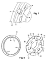
- the figure 3 shows in detail a toc 22 of a radially outer conical ring 20 connected to the hub 8, this toc having lateral bearing faces inclined relative to the axis, which fit on the corresponding faces of the openings 24, inclined according to the same angle to distribute the support force.
- this toc having lateral bearing faces inclined relative to the axis, which fit on the corresponding faces of the openings 24, inclined according to the same angle to distribute the support force.
- openings 24, 26 being equally distributed on the hub 8 is that the operator reverses the openings, using the openings 24, 26 provided for one side, to mount rings on the other side, possibly forcing to bring in the tocs. In this case the inclined faces of the openings 24, 26 are no longer adjusted to those of tocs 22, and the operation of the synchronizer is defective.
- the figure 4 has a radially outer tapered ring 40, having three tocs distributed in a regular manner, two tocs 42 are identical, the third 44 comprising only a lateral bearing face 46 angularly offset outwardly.
- the hub 50 has three regularly distributed openings, two openings 52 are identical, the third 54 also comprises a lateral bearing face 56 angularly offset outwardly, to receive the corresponding toc 44.
- the offset side face 46 of the toc 44 can only fit on one side of the hub 50 in the right set of openings 52, 54 provided for this purpose, this offset preventing introduction into the other game which comprises also an opening 64 with a lateral bearing face 66 offset, but which by symmetry is shifted in the other direction of rotation.
- the symmetrical conical ring located on the other side of the hub 50 can be mounted only in the right set of openings 62, 64.
- each stack of conical rings comprises four rings connected to the hub 50, arranged in groups of two rings, each group using the same set of openings of the hub which allows to limit their number.
- the different sets of openings are angularly offset relative to each other in a regular manner, to obtain a good resistance of the hub.
- the hub 50 can be made from sintered metal powders making it easy to form openings with the lateral slopes, and the conical rings can be made by turning.
- An interesting use of the double synchronizer according to the invention is on a jaw gearbox having different gear ratios made by gears formed by pinions carried by parallel shafts, this gearbox comprising at least one double synchronization device. on two different gear ratios, to synchronize shaft speeds while transmitting torque to the drive wheels of the vehicle.
Landscapes
- Engineering & Computer Science (AREA)
- General Engineering & Computer Science (AREA)
- Mechanical Engineering (AREA)
- Mechanical Operated Clutches (AREA)
Claims (7)
- Mehrfachkegel-Synchronisierung, insbesondere für Kraftfahrzeug-Schaltgetriebe, die eine Nabe (50) aufweist, die fest mit einer Welle (2) verbunden ist, die zwei freie Ritzel (10) aufweist, die axial auf jeder Seite der Nabe angeordnet sind, und zwei identische Stapelungen von Kegelhülsen, die zwischen jedem freien Ritzel und der Nabe angeordnet sind, die in der Reihenfolge der Stapelung Hülsen aufweist, die abwechselnd in Drehung mit der Nabe oder mit dem Ritzel verbunden sind, wobei jede Stapelung durch axiales Gleiten einer Muffe (4), die sie umgibt, gespannt werden kann, wobei jede Hülse (40), die mit der Nabe (50) verbunden ist, eine Reihe von Antriebsmitnehmern (42, 44) aufweist, die regelmäßig verteilt sind und sich in entsprechenden Sätzen durchgehender Öffnungen (52, 54) der Nabe anpassen, wobei die Antriebsmitnehmern (42, 44) und Sätze durchgehender Öffnungen (52, 54) seitliche Auflageflächen haben, die in Bezug auf die Achse der Welle geneigt sind, um eine axiale Kraftkomponente auf der Hülse zu erzielen, dadurch gekennzeichnet, dass diese Antriebsmitnehmer (44) und die entsprechende durchgehende Öffnung (54) der Nabe in Bezug auf andere Antriebsmitnehmer (42) und Öffnungen (52) entlang einer Drehrichtung der Welle (2) verlängert sind, sich geometrisch von den anderen Antriebsmitnehmern (42) und Öffnungen (52) unsymmetrisch unterscheiden.
- Mehrfachkegel-Synchronisierung nach Anspruch 1, dadurch gekennzeichnet, dass jede Hülse (40) zwei Standard-Antriebsmitnehmer (42) und einen unsymmetrischen verlängerten Antriebsmitnehmer (44) aufweist.
- Mehrfachkegel-Synchronisierung nach Anspruch 1 oder 2, dadurch gekennzeichnet, dass die Öffnungssätze für zwei symmetrische Kegelhülsen (40) auf jeder Seite der Nabe (50) winkelig regelmäßig zueinander verteilt sind.
- Mehrfachkegel-Synchronisierung nach einem der vorhergehenden Ansprüche, dadurch gekennzeichnet, dass ein und dieselbe Öffnung (52, 54) der Nabe (50) zwei Antriebsmitnehmer (42, 44), die von zwei übereinander liegenden Hülsen kommen, aufnimmt.
- Mehrfachkegel-Synchronisierung nach Anspruch 4, dadurch gekennzeichnet, dass jede Stapelung von Kegelhülsen vier Hülsen aufweist, die mit der Nabe 50 verbunden sind, die in Gruppen zu zwei Hülsen, die ein und denselben Öffnungssatz der Nabe verwenden, angeordnet sind, wobei diese unterschiedlichen Öffnungssätze winkelig regelmäßig zueinander verteilt sind.
- Mehrfachkegel-Synchronisierung nach einem der vorhergehenden Ansprüche, dadurch gekennzeichnet, dass die Nabe (50) aus gesintertem Metallpulver hergestellt ist.
- Klauen-Schaltgetriebe, das unterschiedliche Gänge aufweist, die aus Zahnradgetrieben bestehen, die Ritzel aufweisen, die mindestens eine doppelte Synchronisierungsvorrichtung auf zwei Gängen aufweisen, die es erlauben, ein Motorantriebsmoment zu übertragen, dadurch gekennzeichnet, dass diese doppelte Synchronisierungsvorrichtung nach einem der vorhergehenden Ansprüche hergestellt ist.
Applications Claiming Priority (1)
| Application Number | Priority Date | Filing Date | Title |
|---|---|---|---|
| FR0850856A FR2927386B1 (fr) | 2008-02-12 | 2008-02-12 | Dispositif de synchronisation multi-cones pour boite de vitesses |
Publications (2)
| Publication Number | Publication Date |
|---|---|
| EP2090796A1 EP2090796A1 (de) | 2009-08-19 |
| EP2090796B1 true EP2090796B1 (de) | 2014-05-07 |
Family
ID=39637708
Family Applications (1)
| Application Number | Title | Priority Date | Filing Date |
|---|---|---|---|
| EP09152015.5A Ceased EP2090796B1 (de) | 2008-02-12 | 2009-02-04 | Vorrichtung zur Mehrfachkegel-Synchronisierung für Schaltgetriebe |
Country Status (2)
| Country | Link |
|---|---|
| EP (1) | EP2090796B1 (de) |
| FR (1) | FR2927386B1 (de) |
Families Citing this family (8)
| Publication number | Priority date | Publication date | Assignee | Title |
|---|---|---|---|---|
| DE102009050525A1 (de) * | 2009-10-23 | 2011-04-28 | Schaeffler Technologies Gmbh & Co. Kg | Synchronisiereinrichtung |
| DE102012112304A1 (de) | 2012-12-14 | 2014-06-18 | Dr. Ing. H.C. F. Porsche Aktiengesellschaft | Synchronisiervorrichtung |
| DE102014110901A1 (de) * | 2014-07-31 | 2016-02-04 | Hoerbiger Antriebstechnik Holding Gmbh | Schiebemuffe und Verfahren zur Herstellung einer Schiebemuffe |
| WO2016203551A1 (ja) * | 2015-06-16 | 2016-12-22 | 株式会社稲坂歯車製作所 | 単車用トランスミッション |
| SE542599C2 (en) * | 2015-08-05 | 2020-06-09 | Scania Cv Ab | A method of controlling a synchronizing arrangement for a retarder, a retarder and a vehicle |
| EP3462051B1 (de) * | 2017-09-27 | 2020-04-15 | Ningbo Geely Automobile Research & Development Co. Ltd. | Übertragungsvorrichtung |
| KR102683791B1 (ko) * | 2019-09-16 | 2024-07-10 | 현대자동차주식회사 | 차량용 콘 클러치 |
| CN111795079B (zh) * | 2020-06-24 | 2024-06-11 | 陕西法士特汽车传动集团有限责任公司 | 一种大容量嵌入式锥面同步器、变速器 |
Family Cites Families (5)
| Publication number | Priority date | Publication date | Assignee | Title |
|---|---|---|---|---|
| WO1987000595A1 (fr) * | 1985-07-26 | 1987-01-29 | Zahnradfabrik Friedrichshafen Ag | Accouplement a griffes avec agencement de synchronisation du blocage |
| JP3378688B2 (ja) * | 1995-01-23 | 2003-02-17 | 日野自動車株式会社 | 変速機の同期装置 |
| US5560461A (en) * | 1995-02-24 | 1996-10-01 | Dana Corporation | Multiple cone synchronizer for vehicle transmission |
| DE29920027U1 (de) * | 1999-11-15 | 2000-01-27 | Hoerbiger Antriebstechnik GmbH, 86956 Schongau | Mehrfach-Synchronisiereinheit für Schaltgetriebe |
| EP1887240A1 (de) * | 2006-08-11 | 2008-02-13 | Sulzer Euroflamm Germany GmbH | Synchronring |
-
2008
- 2008-02-12 FR FR0850856A patent/FR2927386B1/fr not_active Expired - Fee Related
-
2009
- 2009-02-04 EP EP09152015.5A patent/EP2090796B1/de not_active Ceased
Also Published As
| Publication number | Publication date |
|---|---|
| FR2927386A1 (fr) | 2009-08-14 |
| EP2090796A1 (de) | 2009-08-19 |
| FR2927386B1 (fr) | 2010-04-30 |
Similar Documents
| Publication | Publication Date | Title |
|---|---|---|
| EP2090796A1 (de) | Vorrichtung zur Mehrfachkegel-Synchronisierung für Schaltgetriebe | |
| EP3581416B1 (de) | Getriebevorrichtung, insbesondere für elektrofahrzeug | |
| EP3829910A1 (de) | Antriebssystem für ein elektrisches fahrzeug | |
| EP0948721B1 (de) | Wechselgetriebe mit synchronisiertem rückwärtsgang für kraftfahrzeuge | |
| EP4384726B1 (de) | Kupplung für drehende wellen, die mittels wälzlkörpern eine axiale versetzung ermöglicht | |
| EP0174233A1 (de) | Drehschwingungsdämpfer mit grossem Winkelbereich, insbesondere Kupplungsscheibe z.B. für Brennkraftmaschine | |
| CN113124154A (zh) | 一种换挡机构、变速器、动力总成及电动车 | |
| CN102619960A (zh) | 变速器同步器组件 | |
| EP3757414A1 (de) | Vorrichtung zur drehmomentübertragung | |
| EP2055974B1 (de) | Vorrichtung zur Synchronisation mehrerer Kegel zum Einbau auf die Motorwelle eines Getriebes | |
| EP3274609A1 (de) | Drehzahlminderer mit zwei zwischenübertragungsleitungen | |
| FR2922615A1 (fr) | Liaison entre une machine electrique et un arbre primaire de boite de vitesses, pour vehicule hybride | |
| US6189397B1 (en) | Multi-speed automotive transmission using paired helical gearing | |
| JP4121821B2 (ja) | シンクロ装置 | |
| FR3032756A1 (de) | ||
| US8082817B2 (en) | Power transmission mechanism | |
| US7533592B2 (en) | Sleeve spline structure of synchronizer | |
| FR3056160B1 (fr) | Transmission pour vehicule automobile a propulsion electrique | |
| FR3009598A1 (fr) | Commande de vitesse a crabots pour boite de vitesses de vehicule | |
| US9506551B1 (en) | Clutch and gear synchronizer module | |
| FR2993948A1 (fr) | Boite de vitesses pour vehicules automobiles | |
| EP0819864B1 (de) | Kompakte Synchronisiereinrichtung für ein Zahnradwechselgetriebe, insbesondere für ein Kraftfahrzeug | |
| FR3051405A1 (fr) | Appareil de transmission de puissance | |
| EP2529132A1 (de) | Verfahren zum betrieb eines synchrongetriebes in einem getriebegehäuse | |
| EP1382890B1 (de) | Momentunterbrechung-begrenzendes Fahrzeuggetriebe |
Legal Events
| Date | Code | Title | Description |
|---|---|---|---|
| PUAI | Public reference made under article 153(3) epc to a published international application that has entered the european phase |
Free format text: ORIGINAL CODE: 0009012 |
|
| AK | Designated contracting states |
Kind code of ref document: A1 Designated state(s): AT BE BG CH CY CZ DE DK EE ES FI FR GB GR HR HU IE IS IT LI LT LU LV MC MK MT NL NO PL PT RO SE SI SK TR |
|
| AX | Request for extension of the european patent |
Extension state: AL BA RS |
|
| 17P | Request for examination filed |
Effective date: 20100209 |
|
| 17Q | First examination report despatched |
Effective date: 20100302 |
|
| AKX | Designation fees paid |
Designated state(s): DE ES FR GB IT |
|
| GRAP | Despatch of communication of intention to grant a patent |
Free format text: ORIGINAL CODE: EPIDOSNIGR1 |
|
| INTG | Intention to grant announced |
Effective date: 20131211 |
|
| RIN1 | Information on inventor provided before grant (corrected) |
Inventor name: WASCHEUL, MICHAEL Inventor name: LELASSEUX, XAVIER |
|
| GRAS | Grant fee paid |
Free format text: ORIGINAL CODE: EPIDOSNIGR3 |
|
| GRAA | (expected) grant |
Free format text: ORIGINAL CODE: 0009210 |
|
| AK | Designated contracting states |
Kind code of ref document: B1 Designated state(s): DE ES FR GB IT |
|
| REG | Reference to a national code |
Ref country code: GB Ref legal event code: FG4D Free format text: NOT ENGLISH |
|
| REG | Reference to a national code |
Ref country code: DE Ref legal event code: R096 Ref document number: 602009023793 Country of ref document: DE Effective date: 20140618 |
|
| PG25 | Lapsed in a contracting state [announced via postgrant information from national office to epo] |
Ref country code: ES Free format text: LAPSE BECAUSE OF FAILURE TO SUBMIT A TRANSLATION OF THE DESCRIPTION OR TO PAY THE FEE WITHIN THE PRESCRIBED TIME-LIMIT Effective date: 20140507 |
|
| REG | Reference to a national code |
Ref country code: DE Ref legal event code: R097 Ref document number: 602009023793 Country of ref document: DE |
|
| PLBE | No opposition filed within time limit |
Free format text: ORIGINAL CODE: 0009261 |
|
| STAA | Information on the status of an ep patent application or granted ep patent |
Free format text: STATUS: NO OPPOSITION FILED WITHIN TIME LIMIT |
|
| 26N | No opposition filed |
Effective date: 20150210 |
|
| PG25 | Lapsed in a contracting state [announced via postgrant information from national office to epo] |
Ref country code: IT Free format text: LAPSE BECAUSE OF FAILURE TO SUBMIT A TRANSLATION OF THE DESCRIPTION OR TO PAY THE FEE WITHIN THE PRESCRIBED TIME-LIMIT Effective date: 20140507 |
|
| REG | Reference to a national code |
Ref country code: DE Ref legal event code: R097 Ref document number: 602009023793 Country of ref document: DE Effective date: 20150210 |
|
| REG | Reference to a national code |
Ref country code: DE Ref legal event code: R119 Ref document number: 602009023793 Country of ref document: DE |
|
| GBPC | Gb: european patent ceased through non-payment of renewal fee |
Effective date: 20150204 |
|
| REG | Reference to a national code |
Ref country code: FR Ref legal event code: PLFP Year of fee payment: 8 |
|
| PG25 | Lapsed in a contracting state [announced via postgrant information from national office to epo] |
Ref country code: GB Free format text: LAPSE BECAUSE OF NON-PAYMENT OF DUE FEES Effective date: 20150204 Ref country code: DE Free format text: LAPSE BECAUSE OF NON-PAYMENT OF DUE FEES Effective date: 20150901 |
|
| REG | Reference to a national code |
Ref country code: FR Ref legal event code: PLFP Year of fee payment: 9 |
|
| REG | Reference to a national code |
Ref country code: FR Ref legal event code: PLFP Year of fee payment: 10 |
|
| REG | Reference to a national code |
Ref country code: FR Ref legal event code: CA Effective date: 20180312 Ref country code: FR Ref legal event code: CD Owner name: PEUGEOT CITROEN AUTOMOBILES SA, FR Effective date: 20180312 |
|
| PGFP | Annual fee paid to national office [announced via postgrant information from national office to epo] |
Ref country code: FR Payment date: 20220119 Year of fee payment: 14 |
|
| PG25 | Lapsed in a contracting state [announced via postgrant information from national office to epo] |
Ref country code: FR Free format text: LAPSE BECAUSE OF NON-PAYMENT OF DUE FEES Effective date: 20230228 |