EP2090753A2 - Sealing assembly for a turbine engine and corresponding operating method - Google Patents
Sealing assembly for a turbine engine and corresponding operating method Download PDFInfo
- Publication number
- EP2090753A2 EP2090753A2 EP09250302A EP09250302A EP2090753A2 EP 2090753 A2 EP2090753 A2 EP 2090753A2 EP 09250302 A EP09250302 A EP 09250302A EP 09250302 A EP09250302 A EP 09250302A EP 2090753 A2 EP2090753 A2 EP 2090753A2
- Authority
- EP
- European Patent Office
- Prior art keywords
- air seal
- outer air
- seal segment
- support
- brush
- Prior art date
- Legal status (The legal status is an assumption and is not a legal conclusion. Google has not performed a legal analysis and makes no representation as to the accuracy of the status listed.)
- Granted
Links
- 238000007789 sealing Methods 0.000 title claims abstract description 24
- 238000011017 operating method Methods 0.000 title 1
- 238000000034 method Methods 0.000 claims description 4
- 229920001971 elastomer Polymers 0.000 claims description 3
- OKTJSMMVPCPJKN-UHFFFAOYSA-N Carbon Chemical compound [C] OKTJSMMVPCPJKN-UHFFFAOYSA-N 0.000 claims description 2
- 230000003466 anti-cipated effect Effects 0.000 claims description 2
- 229910052799 carbon Inorganic materials 0.000 claims description 2
- 239000002131 composite material Substances 0.000 claims description 2
- 239000000806 elastomer Substances 0.000 claims description 2
- 239000000463 material Substances 0.000 claims description 2
- 239000002184 metal Substances 0.000 claims description 2
- 239000011324 bead Substances 0.000 claims 1
- 238000012423 maintenance Methods 0.000 description 2
- 239000000853 adhesive Substances 0.000 description 1
- 230000001070 adhesive effect Effects 0.000 description 1
- 230000000712 assembly Effects 0.000 description 1
- 238000000429 assembly Methods 0.000 description 1
- 238000005219 brazing Methods 0.000 description 1
- 238000000151 deposition Methods 0.000 description 1
- 238000012986 modification Methods 0.000 description 1
- 230000004048 modification Effects 0.000 description 1
- 238000005507 spraying Methods 0.000 description 1
- 238000003466 welding Methods 0.000 description 1
Images
Classifications
-
- F—MECHANICAL ENGINEERING; LIGHTING; HEATING; WEAPONS; BLASTING
- F01—MACHINES OR ENGINES IN GENERAL; ENGINE PLANTS IN GENERAL; STEAM ENGINES
- F01D—NON-POSITIVE DISPLACEMENT MACHINES OR ENGINES, e.g. STEAM TURBINES
- F01D11/00—Preventing or minimising internal leakage of working-fluid, e.g. between stages
- F01D11/08—Preventing or minimising internal leakage of working-fluid, e.g. between stages for sealing space between rotor blade tips and stator
- F01D11/12—Preventing or minimising internal leakage of working-fluid, e.g. between stages for sealing space between rotor blade tips and stator using a rubstrip, e.g. erodible. deformable or resiliently-biased part
-
- F—MECHANICAL ENGINEERING; LIGHTING; HEATING; WEAPONS; BLASTING
- F04—POSITIVE - DISPLACEMENT MACHINES FOR LIQUIDS; PUMPS FOR LIQUIDS OR ELASTIC FLUIDS
- F04D—NON-POSITIVE-DISPLACEMENT PUMPS
- F04D29/00—Details, component parts, or accessories
- F04D29/08—Sealings
- F04D29/16—Sealings between pressure and suction sides
- F04D29/161—Sealings between pressure and suction sides especially adapted for elastic fluid pumps
- F04D29/164—Sealings between pressure and suction sides especially adapted for elastic fluid pumps of an axial flow wheel
-
- F—MECHANICAL ENGINEERING; LIGHTING; HEATING; WEAPONS; BLASTING
- F16—ENGINEERING ELEMENTS AND UNITS; GENERAL MEASURES FOR PRODUCING AND MAINTAINING EFFECTIVE FUNCTIONING OF MACHINES OR INSTALLATIONS; THERMAL INSULATION IN GENERAL
- F16J—PISTONS; CYLINDERS; SEALINGS
- F16J15/00—Sealings
- F16J15/16—Sealings between relatively-moving surfaces
- F16J15/32—Sealings between relatively-moving surfaces with elastic sealings, e.g. O-rings
- F16J15/3284—Sealings between relatively-moving surfaces with elastic sealings, e.g. O-rings characterised by their structure; Selection of materials
- F16J15/3288—Filamentary structures, e.g. brush seals
-
- F—MECHANICAL ENGINEERING; LIGHTING; HEATING; WEAPONS; BLASTING
- F05—INDEXING SCHEMES RELATING TO ENGINES OR PUMPS IN VARIOUS SUBCLASSES OF CLASSES F01-F04
- F05D—INDEXING SCHEME FOR ASPECTS RELATING TO NON-POSITIVE-DISPLACEMENT MACHINES OR ENGINES, GAS-TURBINES OR JET-PROPULSION PLANTS
- F05D2240/00—Components
- F05D2240/10—Stators
- F05D2240/11—Shroud seal segments
-
- F—MECHANICAL ENGINEERING; LIGHTING; HEATING; WEAPONS; BLASTING
- F05—INDEXING SCHEMES RELATING TO ENGINES OR PUMPS IN VARIOUS SUBCLASSES OF CLASSES F01-F04
- F05D—INDEXING SCHEME FOR ASPECTS RELATING TO NON-POSITIVE-DISPLACEMENT MACHINES OR ENGINES, GAS-TURBINES OR JET-PROPULSION PLANTS
- F05D2240/00—Components
- F05D2240/55—Seals
- F05D2240/56—Brush seals
-
- Y—GENERAL TAGGING OF NEW TECHNOLOGICAL DEVELOPMENTS; GENERAL TAGGING OF CROSS-SECTIONAL TECHNOLOGIES SPANNING OVER SEVERAL SECTIONS OF THE IPC; TECHNICAL SUBJECTS COVERED BY FORMER USPC CROSS-REFERENCE ART COLLECTIONS [XRACs] AND DIGESTS
- Y02—TECHNOLOGIES OR APPLICATIONS FOR MITIGATION OR ADAPTATION AGAINST CLIMATE CHANGE
- Y02T—CLIMATE CHANGE MITIGATION TECHNOLOGIES RELATED TO TRANSPORTATION
- Y02T50/00—Aeronautics or air transport
- Y02T50/60—Efficient propulsion technologies, e.g. for aircraft
Definitions
- This invention relates to a brush shroud assembly for a gas turbine engine.
- a gas turbine engine for an airplane has an outer air seal made of segments. These outer air seal segments form a circular cover or case around the rotating blades of a compressor or turbine. A gap is necessary between the case and blade to prevent the tips of the blades from contacting the case and being damaged. However, this gap reduces the efficiency of the turbine engine by permitting the creation of turbulence and air leakage at the tips of the blades. It is desirable to reduce the space between the outer air seal segment and the rotating blade so as to reduce this turbulence.
- Airplane manufacturers have used plasma spray coatings, feltmetal or rubber between the outer air seal segment and the blade for this purpose. During a break-in period, the blades rub up against these abradable surfaces to provide sufficient clearance for rotation of the blades while providing a seal against turbulence and air leakage between the blade and the outer air seal segment. Typically, worn abradable surfaces are restored as part of an engine overhaul.
- bristle brushes formed as part of the outer air seal segment. Because bristle brushes are formed as part of the outer air seal segment, they are expensive and potentially difficult to replace. Furthermore, the outer air seal segments are specific to the particular design and size of the turbine engine. For example, one outer air seal segment having a brush may fit one particular diameter of turbine engine but not another because the outer air seal segment has a curvature conforming to the specific sized radius of the turbine engine. As a consequence, replacement of the brush requires replacement of the entire outer air seal segment or its repair. A need therefore exists for improved sealing assemblies.
- a sealing assembly for a turbine engine has a brush configured to provide an air seal between an outer air seal segment and a blade.
- a support for the brush is provided.
- the support is configured for attachment to an outer air seal segment.
- the support comprises a flexible planar carrier having a first side and a second side.
- the brush extends from the first side while the second side is for attachment to the outer air seal segment.
- the flexible planar carrier has a stiffness less than a stiffness of the outer air seal segment.
- sealing assembly 10 has brush 14 mounted to support 26.
- Support 26 has first side 34 from which brush 14 extends and second side 38 for attachment to an outer air seal segment (see Figures 4 and 5 ).
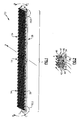
- Support 26 is a flexible planar carrier having thickness T 1 with width W and length L.
- Support 26 is made of a flexible material, such as a flexible metal, flexible carbon composite or an elastomer. The stiffness of support 26 is much less than an anticipated stiffness of the outer air seal segment upon which support 26 will be mounted. With reference to Figure 1 , support 26 may flex in the direction of arrows B or in the direction of arrows C along length L. Support 26 should be flexible enough so as to easily conform to a wide variety of curvatures of an outer air seal segment.
- Figure 2 illustrates a close up view of a section of sealing assembly 10.
- support 26 has bristles 42 that are formed in bunches 46.
- Each bunch 46 is separately attached to support 26 as will be explained.
- These plurality of bunches 46 form brush 14 and are oriented so as to inhibit movement of air in the direction of arrow A.
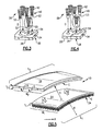
- FIG. 3 shows a close up of another section of sealing assembly 10.
- Each bunch 46 of bristles 42 is disposed over each hole 54, which is sized to receive each bunch 46.
- Bunches 46 are planted in holes 54 in the direction of arrow D.
- Each bunch 46 is attached to support 26 by its own connector 50, here staple 52. In this way, bristles 42 may be easily and inexpensively attached to support 26.
- bunches 46 may be attached by weld ball 53 instead of by staple 52.
- Bunches 46 have weld balls 53 on each bunch 46 and are planted by depositing them in the direction of arrow D into holes 54. Weld balls 53 are then welded to each hole 54.
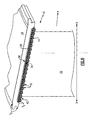
- support 26 has thickness T 1 , which may be less than the thickness T 2 of outer air seal segment 18.
- Outer air seal segment 18 has curvature C as defined by radius R. When all outer air seal segments 18 are joined to form case, they define the diameter of the outer air seal for the turbine engine. Due to the flexibility of support 26, it may be shaped to conform to the curvature C of outer air seal segment 18. In this way, support 26 may be used on a wide variety of outer air seals for a number of differently sized turbine engines having different diameters.
- outer air seal segment 18 has recess 74 with width W 2 and depth D.
- Support 26 may be sized to be received within recess 74 of outer air seal segment 18. Accordingly, recess 74 has width W 2 while support 26 has width W 1 , which is less than or equal to W 2 . Also, support 26 is constructed so that its thickness, T 1 , is less than depth D, so that support 26 will not add to the thickness of outer air seal segment 18.
- support 26 is shown having a curve length L 1 about equal to a curved length L 2 of outer air seal segment 18. However, support 26 may be longer or shorter than length L 2 of outer air seal segment 18. Support 26 may be stored in long rolls so that a maintenance technician may cut support 26 to a length that exactly covers outer air seal segment 18 or may be cut to smaller pieces so that several supports 26 fit across length L 2 of outer air seal segment 18. Thus, support 26 gives the maintenance technician the flexibility to custom fit all or a portion of outer air seal segment 18. Support 26 can even be placed on outer air seal segment 18 without its removal from the engine case. Support 26 is simply disposed over outer air seal segment 18 and moved in the direction of arrow E for mounting on air seal segment 18 by an adhesive, by welding, by brazing or even by stapling to outer air seal segment 18.
- FIG. 6 illustrates sealing assembly 10 in relationship to blade 22, which may be either a compressor blade or a turbine blade.
- Blade 22 rotates about axis X and moves air in the direction of arrow A generally along axis X. As shown, blade 22 is disposed in brush 14 without any gap between bristles 42 and turbine blade 22.
Abstract
Description
- This invention relates to a brush shroud assembly for a gas turbine engine.
- A gas turbine engine for an airplane has an outer air seal made of segments. These outer air seal segments form a circular cover or case around the rotating blades of a compressor or turbine. A gap is necessary between the case and blade to prevent the tips of the blades from contacting the case and being damaged. However, this gap reduces the efficiency of the turbine engine by permitting the creation of turbulence and air leakage at the tips of the blades. It is desirable to reduce the space between the outer air seal segment and the rotating blade so as to reduce this turbulence.
- Airplane manufacturers have used plasma spray coatings, feltmetal or rubber between the outer air seal segment and the blade for this purpose. During a break-in period, the blades rub up against these abradable surfaces to provide sufficient clearance for rotation of the blades while providing a seal against turbulence and air leakage between the blade and the outer air seal segment. Typically, worn abradable surfaces are restored as part of an engine overhaul.
- More recently, manufacturers have begun using bristle brushes formed as part of the outer air seal segment. Because bristle brushes are formed as part of the outer air seal segment, they are expensive and potentially difficult to replace. Furthermore, the outer air seal segments are specific to the particular design and size of the turbine engine. For example, one outer air seal segment having a brush may fit one particular diameter of turbine engine but not another because the outer air seal segment has a curvature conforming to the specific sized radius of the turbine engine. As a consequence, replacement of the brush requires replacement of the entire outer air seal segment or its repair. A need therefore exists for improved sealing assemblies.
- A sealing assembly for a turbine engine has a brush configured to provide an air seal between an outer air seal segment and a blade. A support for the brush is provided. The support is configured for attachment to an outer air seal segment. The support comprises a flexible planar carrier having a first side and a second side. The brush extends from the first side while the second side is for attachment to the outer air seal segment. The flexible planar carrier has a stiffness less than a stiffness of the outer air seal segment.
- The various features and advantages of this invention will become apparent to those skilled in the art from the following detailed description. The drawings that accompany the detailed description can be briefly described as follows.
-
-
Figure 1 illustrates a sealing assembly with brush and support. -
Figure 2 illustrates a close-up view of the brush and support ofFigure 1 , showing bunches of bristles that compose the brush. -
Figure 3 illustrates the attachment of bristles to the support ofFigure 1 . -
Figure 4 illustrates another method of attachment of the bristles to the support ofFigure 1 . -
Figure 5 illustrates the mounting of the support with brush onto outer air seal segment. -
Figure 6 illustrates brush and support mounted to outer air seal segment and disposed next toblade 22. - With reference to
Figure 1 , there is shownsealing assembly 10.Sealing assembly 10 hasbrush 14 mounted to support 26.Support 26 hasfirst side 34 from whichbrush 14 extends andsecond side 38 for attachment to an outer air seal segment (seeFigures 4 and 5 ).Support 26 is a flexible planar carrier having thickness T1 with width W andlength L. Support 26 is made of a flexible material, such as a flexible metal, flexible carbon composite or an elastomer. The stiffness ofsupport 26 is much less than an anticipated stiffness of the outer air seal segment upon whichsupport 26 will be mounted. With reference toFigure 1 ,support 26 may flex in the direction of arrows B or in the direction of arrows C alonglength L. Support 26 should be flexible enough so as to easily conform to a wide variety of curvatures of an outer air seal segment. -
Figure 2 illustrates a close up view of a section ofsealing assembly 10. As shown,support 26 hasbristles 42 that are formed inbunches 46. Eachbunch 46 is separately attached to support 26 as will be explained. These plurality ofbunches 46form brush 14 and are oriented so as to inhibit movement of air in the direction of arrow A. -
Figure 3 shows a close up of another section ofsealing assembly 10. Eachbunch 46 ofbristles 42 is disposed over eachhole 54, which is sized to receive eachbunch 46.Bunches 46 are planted inholes 54 in the direction of arrow D. Eachbunch 46 is attached to support 26 by itsown connector 50, herestaple 52. In this way,bristles 42 may be easily and inexpensively attached to support 26. - Alternatively,
bunches 46 may be attached byweld ball 53 instead of bystaple 52. Bunches 46 haveweld balls 53 on eachbunch 46 and are planted by depositing them in the direction of arrow D intoholes 54.Weld balls 53 are then welded to eachhole 54. - With reference to
Figures 5 and6 , a method of attachingassembly 10 to outerair seal segment 18 is shown. As shown inFigure 5 ,support 26 has thickness T1, which may be less than the thickness T2 of outerair seal segment 18. Outerair seal segment 18 has curvature C as defined by radius R. When all outerair seal segments 18 are joined to form case, they define the diameter of the outer air seal for the turbine engine. Due to the flexibility ofsupport 26, it may be shaped to conform to the curvature C of outerair seal segment 18. In this way,support 26 may be used on a wide variety of outer air seals for a number of differently sized turbine engines having different diameters. - In addition, outer
air seal segment 18 has recess 74 with width W2 anddepth D. Support 26 may be sized to be received withinrecess 74 of outerair seal segment 18. Accordingly,recess 74 has width W2 whilesupport 26 has width W1, which is less than or equal to W2. Also,support 26 is constructed so that its thickness, T1, is less than depth D, so thatsupport 26 will not add to the thickness of outerair seal segment 18. - In
Figure 5 ,support 26 is shown having a curve length L1 about equal to a curved length L2 of outerair seal segment 18. However,support 26 may be longer or shorter than length L2 of outerair seal segment 18.Support 26 may be stored in long rolls so that a maintenance technician may cutsupport 26 to a length that exactly covers outerair seal segment 18 or may be cut to smaller pieces so that several supports 26 fit across length L2 of outerair seal segment 18. Thus,support 26 gives the maintenance technician the flexibility to custom fit all or a portion of outerair seal segment 18.Support 26 can even be placed on outerair seal segment 18 without its removal from the engine case.Support 26 is simply disposed over outerair seal segment 18 and moved in the direction of arrow E for mounting onair seal segment 18 by an adhesive, by welding, by brazing or even by stapling to outerair seal segment 18. -
Figure 6 illustratessealing assembly 10 in relationship toblade 22, which may be either a compressor blade or a turbine blade.Blade 22 rotates about axis X and moves air in the direction of arrow A generally along axis X. As shown,blade 22 is disposed inbrush 14 without any gap betweenbristles 42 andturbine blade 22. - The foregoing description shall be interpreted as illustrative and not in any limiting sense. A worker of ordinary skill in the art would recognize that certain modifications would come within the scope of this invention. For that reason, the follow claims should be studied to determine the true scope and content of this invention.
Claims (15)
- A sealing assembly (10) for a turbine engine, comprising:a brush (14) configured to provide an air seal between an outer air seal segment (18) and a blade (22);a support (26) for said brush (14), said support (26) configured for attachment to the outer air seal segment (18); and
wherein said support (26) comprises a flexible planar carrier having a first side (34) and a second side (38), said brush (14) extending from said first side (34), said second side (38) for attachment to the outer air seal segment (18), and said flexible planar carrier having a stiffness less than a stiffness of the outer air seal segment. - The sealing assembly of Claim 1 wherein said brush (14) comprises bristles (42).
- The sealing assembly of Claim 2 including a plurality of holes (54) in said support (26) for receiving said bristles (42).
- The sealing assembly of Claim 2 or 3 wherein said bristles (42) are formed into a bunch (46) by a connector (50;52;53).
- The sealing assembly of Claim 4 wherein said connector (50;52;53) is attached to said support (26).
- The sealing assembly of Claim 4 or 5 wherein said connector comprises a staple (52) or a weld bead (53).
- A sealing assembly (10) for a turbine engine, comprising:an outer air seal segment (18);a brush (14) comprising bristles (42), said brush (14) configured to provide an air seal between said outer air seal segment (18) and a blade (22);a support (26) attached to said brush (14) and attached to said outer air seal segment (18); andwherein said support (26) comprises a flexible planar carrier having a first side and a second side, said brush (14) extending from said first side, said second side for attachment to the outer air seal segment (18), and said flexible planar carrier having a stiffness less than a stiffness of said outer air seal segment (18).
- The sealing assembly of any preceding Claim wherein said support (26) is made of one of a flexible metal, a flexible carbon composite material, and an elastomer material.
- The sealing assembly of any preceding Claim wherein said planar carrier (26) has a thickness (T), a width (W) and a length (L), said thickness (T) defined by said first side (34) and said second side (38).
- The sealing assembly of Claim 9 wherein said thickness (T) is less than an anticipated thickness or thickness (T2) of an or said outer air seal segment (18).
- The sealing assembly of Claim 9 or 10, wherein said width (W) is sized to be received within the outer air seal segment (18).
- The sealing assembly of Claim 9, 10 or 11 wherein said outer air seal segment (18) has a recess (74) having a depth, said depth at least as great as said carrier thickness.
- A method of sealing an outer air seal for a turbine engine, comprising the steps of:providing a brush (14) configured to provide an air seal between an outer air seal segment (18) and a blade (22), the outer air seal segment (18) having a curvature;providing a support (26) attached to the brush (14), the support (26) comprises a flexible planar carrier having a first side and a second side, the brush (14) extending from the first side, the second side for attachment to the outer air seal segment (18);flexing the support (26) to conform to the curvature of the outer air seal segment (18); andmounting the support (26) to the outer air seal segment (18).
- The method of Claim 13 including the step of reducing a length (L1) of the support (26) to a size at least as large a length (L2) of the outer air seal segment (18).
- A sealing assembly for a turbine engine comprising:an outer air seal segment (18); andan assembly as claimed in any of Claims 1 to 6 or 8 to 12, said support (26) of said assembly attached to said outer air seal segment.
Applications Claiming Priority (1)
| Application Number | Priority Date | Filing Date | Title |
|---|---|---|---|
| US12/032,771 US8414254B2 (en) | 2008-02-18 | 2008-02-18 | Sealing assembly for a turbine engine |
Publications (3)
| Publication Number | Publication Date |
|---|---|
| EP2090753A2 true EP2090753A2 (en) | 2009-08-19 |
| EP2090753A3 EP2090753A3 (en) | 2012-05-16 |
| EP2090753B1 EP2090753B1 (en) | 2013-12-11 |
Family
ID=40427246
Family Applications (1)
| Application Number | Title | Priority Date | Filing Date |
|---|---|---|---|
| EP09250302.8A Expired - Fee Related EP2090753B1 (en) | 2008-02-18 | 2009-02-06 | Sealing assembly for a turbine engine and corresponding operating method |
Country Status (2)
| Country | Link |
|---|---|
| US (1) | US8414254B2 (en) |
| EP (1) | EP2090753B1 (en) |
Cited By (1)
| Publication number | Priority date | Publication date | Assignee | Title |
|---|---|---|---|---|
| GB2537825A (en) * | 2015-04-22 | 2016-11-02 | Francis Mitchell Martin | Universal seal |
Families Citing this family (2)
| Publication number | Priority date | Publication date | Assignee | Title |
|---|---|---|---|---|
| US20150285259A1 (en) * | 2014-04-05 | 2015-10-08 | Arthur John Wennerstrom | Filament-Wound Tip-Shrouded Axial Compressor or Fan Rotor System |
| US10183723B2 (en) | 2015-03-12 | 2019-01-22 | Sram, Llc | Bicycle control device |
Citations (2)
| Publication number | Priority date | Publication date | Assignee | Title |
|---|---|---|---|---|
| US6257588B1 (en) * | 1998-09-22 | 2001-07-10 | General Electric Company | Brush seal and rotary machine including such brush seal |
| US20050179207A1 (en) * | 2000-11-06 | 2005-08-18 | Advanced Components & Materials, Inc. | Compliant brush shroud assembly for gas turbine engine compressors |
Family Cites Families (18)
| Publication number | Priority date | Publication date | Assignee | Title |
|---|---|---|---|---|
| US885032A (en) * | 1907-06-24 | 1908-04-21 | Sebastian Ziani De Ferranti | Fluid packing. |
| US3818534A (en) * | 1972-03-30 | 1974-06-25 | Boucherie G Noamloze Vennootsc | Brush |
| GB8712681D0 (en) * | 1987-05-29 | 1987-07-01 | Cross Mfg Co 1938 Ltd | Brush seals |
| US6131910A (en) | 1992-11-19 | 2000-10-17 | General Electric Co. | Brush seals and combined labyrinth and brush seals for rotary machines |
| US7181843B1 (en) | 1995-09-28 | 2007-02-27 | United Technologies Corporation | Method of manufacturing a brush seal |
| US5752802A (en) | 1996-12-19 | 1998-05-19 | Solar Turbines Incorporated | Sealing apparatus for airfoils of gas turbine engines |
| US6027121A (en) * | 1997-10-23 | 2000-02-22 | General Electric Co. | Combined brush/labyrinth seal for rotary machines |
| CA2266831C (en) | 1998-04-01 | 2004-07-13 | Mitsubishi Heavy Industries, Ltd. | Seal structure for gas turbine |
| US6170831B1 (en) | 1998-12-23 | 2001-01-09 | United Technologies Corporation | Axial brush seal for gas turbine engines |
| US6139019A (en) | 1999-03-24 | 2000-10-31 | General Electric Company | Seal assembly and rotary machine containing such seal |
| US6206629B1 (en) * | 1999-08-18 | 2001-03-27 | General Electric Company | Turbine brush seal protection device and method |
| US6217277B1 (en) | 1999-10-05 | 2001-04-17 | Pratt & Whitney Canada Corp. | Turbofan engine including improved fan blade lining |
| DE10009432C1 (en) * | 2000-02-28 | 2001-12-06 | Mtu Aero Engines Gmbh | Brush for a brush seal |
| US6488471B1 (en) * | 2000-10-04 | 2002-12-03 | The United States Of America As Represented By The Secretary Of The Air Force | Gas-turbine brush seals with permanent radial gap |
| DE10196832T1 (en) | 2000-11-06 | 2003-11-13 | Advanced Components & Material | Spring brush casing arrangement for compressors of gas turbine engines |
| DE10122732C2 (en) | 2001-05-10 | 2003-04-30 | Mtu Aero Engines Gmbh | Arrangement for a non-hermetic seal |
| US6779799B2 (en) | 2002-11-27 | 2004-08-24 | General Electric Company | Sealing apparatus for electrical generator ventilation system |
| US7270333B2 (en) | 2002-11-27 | 2007-09-18 | United Technologies Corporation | Brush seal with adjustable clearance |
-
2008
- 2008-02-18 US US12/032,771 patent/US8414254B2/en not_active Expired - Fee Related
-
2009
- 2009-02-06 EP EP09250302.8A patent/EP2090753B1/en not_active Expired - Fee Related
Patent Citations (2)
| Publication number | Priority date | Publication date | Assignee | Title |
|---|---|---|---|---|
| US6257588B1 (en) * | 1998-09-22 | 2001-07-10 | General Electric Company | Brush seal and rotary machine including such brush seal |
| US20050179207A1 (en) * | 2000-11-06 | 2005-08-18 | Advanced Components & Materials, Inc. | Compliant brush shroud assembly for gas turbine engine compressors |
Cited By (1)
| Publication number | Priority date | Publication date | Assignee | Title |
|---|---|---|---|---|
| GB2537825A (en) * | 2015-04-22 | 2016-11-02 | Francis Mitchell Martin | Universal seal |
Also Published As
| Publication number | Publication date |
|---|---|
| US20090208330A1 (en) | 2009-08-20 |
| EP2090753A3 (en) | 2012-05-16 |
| EP2090753B1 (en) | 2013-12-11 |
| US8414254B2 (en) | 2013-04-09 |
Similar Documents
| Publication | Publication Date | Title |
|---|---|---|
| US8696320B2 (en) | Gas turbine having seal assembly with coverplate and seal | |
| EP1741878B1 (en) | Fluid flow machine | |
| US7918643B2 (en) | Sealing arrangement in a gas turbine engine | |
| JP4776262B2 (en) | Rotating seal device for turbine bucket cooling circuit | |
| US8419361B2 (en) | Anti fret liner assembly | |
| EP2620591B1 (en) | Gas turbine engine stator vane assembly with inner shroud | |
| US6681486B2 (en) | Method of forming brush seals between rotating components | |
| EP1860283A2 (en) | Fan casing for a gas turbine engine | |
| EP1967698A2 (en) | Labyrinth and brush seal assembly, and associated mounting process | |
| US8282356B2 (en) | Apparatus and method for reducing wear in disk lugs | |
| US20100232939A1 (en) | Machine Seal Assembly | |
| US20140304989A1 (en) | Rotor blade assembly tool for gas turbine engine | |
| US10895159B2 (en) | Removable anti-wear part for blade tip | |
| US20080118350A1 (en) | Turbine seal guards | |
| EP2090753B1 (en) | Sealing assembly for a turbine engine and corresponding operating method | |
| JP2017031970A (en) | Compressor patch ring, and method of attaching compressor patch ring | |
| EP1918523A2 (en) | Turbine and rotor blade with brush seal | |
| GB2330630A (en) | Brush seal for use on rough rotating surfaces | |
| EP1363051B1 (en) | Brush seal and method of installing a brush seal in an apparatus. | |
| EP2157288B1 (en) | Sealing means | |
| US20170058916A1 (en) | Gas turbine fan fairing platform and method of fairing a root leading edge of a fan blade of a gas turbine engine | |
| EP1353097B1 (en) | Brush seal | |
| US20190186280A1 (en) | System and Method for Minimizing the Turbine Blade to Vane Platform Overlap Gap | |
| JP5730010B2 (en) | Turbine shaft seal and steam turbine having the same | |
| EP3438512B1 (en) | Seal segment and rotary machine |
Legal Events
| Date | Code | Title | Description |
|---|---|---|---|
| PUAI | Public reference made under article 153(3) epc to a published international application that has entered the european phase |
Free format text: ORIGINAL CODE: 0009012 |
|
| AK | Designated contracting states |
Kind code of ref document: A2 Designated state(s): AT BE BG CH CY CZ DE DK EE ES FI FR GB GR HR HU IE IS IT LI LT LU LV MC MK MT NL NO PL PT RO SE SI SK TR |
|
| AX | Request for extension of the european patent |
Extension state: AL BA RS |
|
| PUAL | Search report despatched |
Free format text: ORIGINAL CODE: 0009013 |
|
| AK | Designated contracting states |
Kind code of ref document: A3 Designated state(s): AT BE BG CH CY CZ DE DK EE ES FI FR GB GR HR HU IE IS IT LI LT LU LV MC MK MT NL NO PL PT RO SE SI SK TR |
|
| AX | Request for extension of the european patent |
Extension state: AL BA RS |
|
| RIC1 | Information provided on ipc code assigned before grant |
Ipc: F01D 11/12 20060101AFI20120411BHEP Ipc: F16J 15/32 20060101ALI20120411BHEP |
|
| 17P | Request for examination filed |
Effective date: 20121114 |
|
| AKX | Designation fees paid |
Designated state(s): DE GB |
|
| GRAP | Despatch of communication of intention to grant a patent |
Free format text: ORIGINAL CODE: EPIDOSNIGR1 |
|
| INTG | Intention to grant announced |
Effective date: 20130620 |
|
| GRAS | Grant fee paid |
Free format text: ORIGINAL CODE: EPIDOSNIGR3 |
|
| GRAA | (expected) grant |
Free format text: ORIGINAL CODE: 0009210 |
|
| AK | Designated contracting states |
Kind code of ref document: B1 Designated state(s): DE GB |
|
| REG | Reference to a national code |
Ref country code: GB Ref legal event code: FG4D |
|
| REG | Reference to a national code |
Ref country code: DE Ref legal event code: R096 Ref document number: 602009020642 Country of ref document: DE Effective date: 20140206 |
|
| REG | Reference to a national code |
Ref country code: DE Ref legal event code: R097 Ref document number: 602009020642 Country of ref document: DE |
|
| PLBE | No opposition filed within time limit |
Free format text: ORIGINAL CODE: 0009261 |
|
| STAA | Information on the status of an ep patent application or granted ep patent |
Free format text: STATUS: NO OPPOSITION FILED WITHIN TIME LIMIT |
|
| 26N | No opposition filed |
Effective date: 20140912 |
|
| REG | Reference to a national code |
Ref country code: DE Ref legal event code: R097 Ref document number: 602009020642 Country of ref document: DE Effective date: 20140912 |
|
| REG | Reference to a national code |
Ref country code: DE Ref legal event code: R082 Ref document number: 602009020642 Country of ref document: DE Representative=s name: SCHMITT-NILSON SCHRAUD WAIBEL WOHLFROM PATENTA, DE |
|
| REG | Reference to a national code |
Ref country code: DE Ref legal event code: R082 Ref document number: 602009020642 Country of ref document: DE Representative=s name: SCHMITT-NILSON SCHRAUD WAIBEL WOHLFROM PATENTA, DE Ref country code: DE Ref legal event code: R081 Ref document number: 602009020642 Country of ref document: DE Owner name: UNITED TECHNOLOGIES CORP. (N.D.GES.D. STAATES , US Free format text: FORMER OWNER: UNITED TECHNOLOGIES CORP., HARTFORD, CONN., US |
|
| PGFP | Annual fee paid to national office [announced via postgrant information from national office to epo] |
Ref country code: GB Payment date: 20220124 Year of fee payment: 14 Ref country code: DE Payment date: 20220119 Year of fee payment: 14 |
|
| REG | Reference to a national code |
Ref country code: DE Ref legal event code: R081 Ref document number: 602009020642 Country of ref document: DE Owner name: RAYTHEON TECHNOLOGIES CORPORATION (N.D.GES.D.S, US Free format text: FORMER OWNER: UNITED TECHNOLOGIES CORP. (N.D.GES.D. STAATES DELAWARE), FARMINGTON, CONN., US |
|
| REG | Reference to a national code |
Ref country code: DE Ref legal event code: R119 Ref document number: 602009020642 Country of ref document: DE |
|
| GBPC | Gb: european patent ceased through non-payment of renewal fee |
Effective date: 20230206 |
|
| PG25 | Lapsed in a contracting state [announced via postgrant information from national office to epo] |
Ref country code: GB Free format text: LAPSE BECAUSE OF NON-PAYMENT OF DUE FEES Effective date: 20230206 |
|
| PG25 | Lapsed in a contracting state [announced via postgrant information from national office to epo] |
Ref country code: GB Free format text: LAPSE BECAUSE OF NON-PAYMENT OF DUE FEES Effective date: 20230206 Ref country code: DE Free format text: LAPSE BECAUSE OF NON-PAYMENT OF DUE FEES Effective date: 20230901 |