EP2090511B1 - Verfahren und Wickeleinheit zum Falten eines Bogens zum Umwickeln eines Zigarettenbündels - Google Patents
Verfahren und Wickeleinheit zum Falten eines Bogens zum Umwickeln eines Zigarettenbündels Download PDFInfo
- Publication number
- EP2090511B1 EP2090511B1 EP09152615A EP09152615A EP2090511B1 EP 2090511 B1 EP2090511 B1 EP 2090511B1 EP 09152615 A EP09152615 A EP 09152615A EP 09152615 A EP09152615 A EP 09152615A EP 2090511 B1 EP2090511 B1 EP 2090511B1
- Authority
- EP
- European Patent Office
- Prior art keywords
- wrapping
- cigarettes
- sheet
- tubular spindle
- group
- Prior art date
- Legal status (The legal status is an assumption and is not a legal conclusion. Google has not performed a legal analysis and makes no representation as to the accuracy of the status listed.)
- Active
Links
- 235000019504 cigarettes Nutrition 0.000 title claims abstract description 116
- 238000000034 method Methods 0.000 title claims abstract description 18
- 230000000295 complement effect Effects 0.000 claims description 3
- 230000006835 compression Effects 0.000 claims 1
- 238000007906 compression Methods 0.000 claims 1
- 238000012856 packing Methods 0.000 description 6
- 241000208125 Nicotiana Species 0.000 description 5
- 235000002637 Nicotiana tabacum Nutrition 0.000 description 5
- 238000007789 sealing Methods 0.000 description 4
- 230000002093 peripheral effect Effects 0.000 description 3
- 235000016639 Syzygium aromaticum Nutrition 0.000 description 1
- 244000223014 Syzygium aromaticum Species 0.000 description 1
- 125000003118 aryl group Chemical group 0.000 description 1
- 230000008020 evaporation Effects 0.000 description 1
- 238000001704 evaporation Methods 0.000 description 1
- 239000011888 foil Substances 0.000 description 1
- 239000000463 material Substances 0.000 description 1
- 235000013599 spices Nutrition 0.000 description 1
- 239000000126 substance Substances 0.000 description 1
- 238000011144 upstream manufacturing Methods 0.000 description 1
Images


Classifications
-
- B—PERFORMING OPERATIONS; TRANSPORTING
- B65—CONVEYING; PACKING; STORING; HANDLING THIN OR FILAMENTARY MATERIAL
- B65B—MACHINES, APPARATUS OR DEVICES FOR, OR METHODS OF, PACKAGING ARTICLES OR MATERIALS; UNPACKING
- B65B19/00—Packaging rod-shaped or tubular articles susceptible to damage by abrasion or pressure, e.g. cigarettes, cigars, macaroni, spaghetti, drinking straws or welding electrodes
- B65B19/02—Packaging cigarettes
- B65B19/22—Wrapping the cigarettes; Packaging the cigarettes in containers formed by folding wrapping material around formers
- B65B19/223—Wrapping the cigarettes; Packaging the cigarettes in containers formed by folding wrapping material around formers in a curved path; in a combination of straight and curved paths, e.g. on rotary tables or other endless conveyors
-
- B—PERFORMING OPERATIONS; TRANSPORTING
- B65—CONVEYING; PACKING; STORING; HANDLING THIN OR FILAMENTARY MATERIAL
- B65B—MACHINES, APPARATUS OR DEVICES FOR, OR METHODS OF, PACKAGING ARTICLES OR MATERIALS; UNPACKING
- B65B19/00—Packaging rod-shaped or tubular articles susceptible to damage by abrasion or pressure, e.g. cigarettes, cigars, macaroni, spaghetti, drinking straws or welding electrodes
- B65B19/02—Packaging cigarettes
- B65B19/22—Wrapping the cigarettes; Packaging the cigarettes in containers formed by folding wrapping material around formers
- B65B19/24—Wrapping the cigarettes; Packaging the cigarettes in containers formed by folding wrapping material around formers using hollow mandrels through which groups of cigarettes are fed
-
- B—PERFORMING OPERATIONS; TRANSPORTING
- B65—CONVEYING; PACKING; STORING; HANDLING THIN OR FILAMENTARY MATERIAL
- B65B—MACHINES, APPARATUS OR DEVICES FOR, OR METHODS OF, PACKAGING ARTICLES OR MATERIALS; UNPACKING
- B65B65/00—Details peculiar to packaging machines and not otherwise provided for; Arrangements of such details
- B65B65/003—Packaging lines, e.g. general layout
- B65B65/006—Multiple parallel packaging lines
-
- B—PERFORMING OPERATIONS; TRANSPORTING
- B65—CONVEYING; PACKING; STORING; HANDLING THIN OR FILAMENTARY MATERIAL
- B65B—MACHINES, APPARATUS OR DEVICES FOR, OR METHODS OF, PACKAGING ARTICLES OR MATERIALS; UNPACKING
- B65B11/00—Wrapping, e.g. partially or wholly enclosing, articles or quantities of material, in strips, sheets or blanks, of flexible material
- B65B11/06—Wrapping articles, or quantities of material, by conveying wrapper and contents in common defined paths
- B65B11/38—Wrapping articles, or quantities of material, by conveying wrapper and contents in common defined paths in a combination of straight and curved paths
- B65B11/40—Wrapping articles, or quantities of material, by conveying wrapper and contents in common defined paths in a combination of straight and curved paths to fold the wrappers in tubular form about contents
- B65B11/42—Wrapping articles, or quantities of material, by conveying wrapper and contents in common defined paths in a combination of straight and curved paths to fold the wrappers in tubular form about contents and then to form closing folds of similar form at opposite ends of the tube
Definitions
- the present invention relates to a method and wrapping unit for folding a sheet of wrapping about a group of cigarettes.
- a packet of cigarettes normally comprises an inner package comprising a group of cigarettes wrapped in a sheet of inner wrapping; and an outer package enclosing the inner package, and which may be cup-shaped and comprise a sheet of outer wrapping folded about the inner package (soft packet of cigarettes), or may comprise a rigid, hinged-lid box formed by folding a rigid blank about the inner package (rigid packet of cigarettes).
- Folding the sheet of inner wrapping about the group of cigarettes has been found to damage the ends of the cigarettes by producing local deformation (at both the filter-tipped end and the plain end) and/or tobacco fallout (i.e. loss of tobacco, obviously only from the plain tips at the opposite end to the filters). Damage by folding the sheet of inner wrapping about the group of cigarettes mostly applies to the cigarettes at the corners of the group, but is nevertheless evident in all the outer cigarettes, i.e. located along the fold lines of the sheet of inner wrapping. Moreover, the stiffness of the sheet of inner wrapping deforms the ends of the cigarettes, thus resulting in an inner package with rounded as opposed to square edges. This is particularly undesirable by producing an overall look of the exposed portion of the inner package that is not very popular with consumers, who tend to opt for inner packages with sharp, well pronounced edges.
- Tobacco is highly sensitive to environment. That is, in contact with the atmosphere, its organic characteristics tend to vary alongside variations in humidity (by losing or absorbing too much moisture) or due to evaporation of the volatile substances with which the tobacco is impregnated (especially in the case of aromatic cigarettes treated with spices such as cloves).
- the inner package is airtight and comprises a sheet of airtight, heat-seal wrapping. Folding a sheet of airtight inner wrapping, however, is particularly damaging to the cigarettes, by being thicker (and therefore stiffer) than conventional sheets of foil inner wrapping.
- US3412520A1 discloses methods of wrapping blocks of cigarettes, wherein a wrapper blank that is longer and wider than a block of cigarettes to be wrapped is provided at each of two opposite with two slits of which one starts from the corresponding wrapper blank edge and the other is angular, preferably rectangular, to and meets the first slit, to form flaps at said opposite sides of the wrapper blank.
- the blank is folded about the article to be wrapped along two parallel lines connecting ends of said other slots.
- Protruding side portions of the wrapper blank carry the flaps. All the protruding side portions are turned to lie flat against the article, and the flaps protruding from side portions beyond the article are turned to lie flat against portions of the wrapper blank.
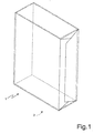
- Number 1 in Figure 1 indicates as a whole a package of cigarettes enclosing a parallelepiped-shaped group 2 of cigarettes, and which can be inserted inside a known rigid, hinged-lid cigarette packet.
- Package 1 is formed by folding a rectangular sheet 6 of wrapping (shown flat in Figure 2 ) made of airtight, heat-seal plastic material directly about group 2 of cigarettes, so that it directly contacts the cigarettes. Once sheet 6 of wrapping is folded about group 2 of cigarettes to form package 1, the shape of package 1 is stabilized by heat sealing the superimposed portions of sheet 6 of wrapping. Number 10 in Figure 2 indicates as a whole a packing machine for producing package 1 as described above.
- Packing machine 10 comprises a group-forming unit (not shown in Figure 2 ) for successively forming groups 2 of cigarettes; and a wrapping unit 12 ( Figure 2 ) on which a sheet 6 of wrapping is wrapped and heat sealed about each group 2 of cigarettes. It is important to bear in mind that packing machine 10 may comprise only the group-forming unit (not shown in Figure 2 ) and wrapping unit 12; in which case, each package 1 described above is a finished marketable product. Alternatively, packing machine 10 may comprise a known further packing station to enclose each package 1 in an outer package, which may be cup-shaped and comprise a sheet of outer wrapping folded about package 1 (soft packet of cigarettes), or may comprise a rigid, hinged-lid box formed by folding a rigid blank about package 1 (rigid packet of cigarettes).
- Groups 2 of cigarettes are transferred from the group-forming unit to wrapping unit 12 at a transfer station 24 defined between the group-forming unit (not shown) and wrapping unit 12. More specifically, transfer station 24 comprises a transfer device 25 in turn comprising two pushers 26 for transferring two groups 2 of cigarettes simultaneously from the group-forming unit to wrapping unit 12.
- Wrapping unit 12 comprises two coaxial, superimposed input wheels 27, which receive and convey two groups 2 of cigarettes simultaneously.
- Each input wheel 27 is horizontal, rotates in steps about a common vertical axis 28 of rotation, and supports two peripheral pockets 29, each for housing a group 2 of cigarettes.
- Wrapping unit 12 also comprises two coaxial, superimposed wrapping wheels 30, which simultaneously receive two groups 2 of cigarettes wrapped partly in respective sheets 6 of wrapping, each folded into a U.
- Each wrapping wheel 30 is horizontal, rotates in steps about a common vertical axis 31 of rotation, and supports two peripheral pockets 32, each for housing a group 2 of cigarettes wrapped partly in a respective sheet 6 of wrapping.
- two sheets 6 of wrapping are fed simultaneously along a vertical feed path to engage two groups 2 of cigarettes as they are transferred from the two input wheels 27 to the two wrapping wheels 30.
- Each wrapping wheel 30 has known fixed and movable folding members (not shown) for folding the ends of each sheet 6 of wrapping about respective group 2 of cigarettes to form a package 1; and a sealing device 34 for heat sealing the superimposed end portions of each sheet 6 of wrapping.
- wrapping unit 12 comprises two straight folding devices 35, each of which receives an unfinished package 1 from a respective wrapping wheel 30, and folds the sides of respective sheet 6 of wrapping about respective group 2 of cigarettes to complete package 1.
- Each folding device 35 preferably comprises fixed folding screws.
- two sealing devices 36 heat seal the superimposed lateral portions of each sheet 6 of wrapping.
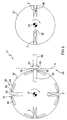
- FIG 3 shows a larger-scale plan view of feed station 33 of wrapping unit 12 in Figure 2 .
- wrapping unit 12 comprises two tubular spindles 49 (only one shown in Figure 3 ) located upstream from feed station 33, and through which are fed two respective groups 2 of cigarettes from the two input wheels 27.
- Each peripheral pocket 32 of each wrapping wheel 30 has an inlet/outlet opening defining a seat 50 for a convex outlet end 51 of respective tubular spindle 49; and each tubular spindle 49 is moved, by known actuating means (not shown) and back and forth in the travelling direction of groups 2 of cigarettes, to and from a position in which outlet end 51 engages the inlet/outlet opening of corresponding pocket 32.
- each tubular spindle 49 performs a reciprocating movement comprising a forward movement, in the travelling direction of group 2 of cigarettes, which causes tubular spindle 49 to intercept sheet 6 of wrapping (as described in detail below), and a return movement in the opposition direction to the travelling direction of group 2 of cigarettes.
- each tubular spindle 49 that contacts sheets 6 of wrapping preferably has a number of suction holes (not shown) connected to a suction source not shown, and which serve to hold sheet 6 of wrapping in the correct position on outlet end 51 of tubular spindle 49 and prevent it from slipping with respect to tubular spindle 49.
- outlet end 51 of each tubular spindle 49 is preferably truncated-cone-shaped, tapering in the travelling direction of group 2 of cigarettes, and the inlet end of seat 50 is also truncated-cone-shaped and complementary with the truncated-cone shape of outlet end 51 of tubular spindle 49.
- a movable pusher 52 moving back and forth in the travelling direction of groups 2 of cigarettes, is connected to each input wheel 27 to expel a group 2 of cigarettes from a pocket 29 of input wheel 27 and through a respective tubular spindle 49 into a pocket 32 of respective wrapping wheel 30.
- each pocket 32 of each wrapping wheel 30 has folding members 53 located on opposite sides of the inlet/outlet opening of pocket 32, and movable between a rest position ( Figures 3 , 4, 5, 7 ) in which folding members 53 are withdrawn inside wrapping wheel 30, and a work position ( Figure 6 ) in which folding members 53 project perpendicularly from wrapping wheel 30.
- folding members 53 of each pocket 32 comprise two folders 54 hinged to wrapping wheel 30 and rotated about respective axes 55 of rotation, parallel to the axis 31 of rotation of wrapping wheel 30, by a cam actuating system not shown.
- folding members 53 of each pocket 32 comprise two folders 54 fitted to wrapping wheel 30 and slid radially with respect to wrapping wheel 30 by a cam actuating system.
- group 2 of cigarettes is expelled from pocket 29 of input wheel 27 into tubular spindle 49 by a pusher 52. As it is inserted inside tubular spindle 49, group 2 of cigarettes may be compressed laterally by the taper of the inner channel of tubular spindle 49.
- tubular spindle 49 is stationary in a withdrawn position ( Figure 4 ), and defines, with pocket 32 of wrapping wheel 30 and at feed station 33, a gap through which a sheet 6 of wrapping is fed.
- Tubular spindle 49 is then moved towards wrapping wheel 30, so that, before the leading end of group 2 of cigarettes reaches sheet 6 of wrapping, the outlet end 51 of tubular spindle 49 engages seat 50 of pocket 32 ( Figure 5 ) and folds sheet 6 of wrapping into a U.
- folding members 53 of pocket 32 are operated to move from the rest position ( Figure 5 ) to the work position ( Figure 6 ) to complete folding sheet 6 of wrapping into a U on tubular spindle 49.
- tubular spindle 49 returns to the withdrawn position in the opposite direction to the travelling direction of groups 2 of cigarettes, while group 2 of cigarettes is kept moving by pusher 52 and inserted inside pocket 32 together with sheet 6 of wrapping, which slides off tubular spindle 49 and wraps onto group 2 of cigarettes ( Figure 7 ).
- Each sheet 6 of wrapping is therefore folded into a U, not by the axial thrust exerted on it by the cigarettes in group 2, but by the thrust exerted by tubular spindle 49, which acts as a folder.
- the cigarettes in group 2 therefore undergo absolutely no axial stress and, hence, no deformation.
- group 2 of cigarettes is fed along one path, while sheet 6 of wrapping is fed perpendicularly to the path of group 2 of cigarettes.
- a tubular spindle 49 is fed along the path of group 2 of cigarettes to intercept and fold sheet 6 of wrapping into a U about tubular spindle 49; and, finally, group 2 of cigarettes is fed through tubular spindle 49 (which by then is moving in the opposite direction) to slide the U-folded sheet 6 of wrapping off tubular spindle 49 and onto group 2 of cigarettes.
- each tubular spindle 49 is of limited travel, and folds sheet 6 of wrapping into a U against seat 50 of a pocket 32 of wrapping wheel 30.
- each tubular spindle 49 has a longer travel, and folds sheet 6 of wrapping into a U against fixed folders 56.
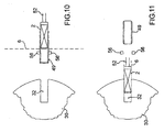
- tubular spindle 49 is stationary in a withdrawn position ( Figure 8 ), and defines, with pocket 32 of wrapping wheel 30 and at feed station 33, a gap through which a sheet 6 of wrapping is fed.
- Tubular spindle 49 is then moved towards wrapping wheel 30, so that the outlet end 51 of tubular spindle 49 engages and folds sheet 6 of wrapping into a U against fixed folders 56 ( Figure 9 ).
- group 2 of cigarettes is expelled from pocket 29 of input wheel 27 into tubular spindle 49 by pusher 52.
- group 2 of cigarettes may be compressed laterally by the taper of the inner channel of tubular spindle 49.
- tubular spindle 49 returns to the withdrawn position in the opposite direction to the travelling direction of groups 2 of cigarettes, while group 2 of cigarettes is kept moving by pusher 52 and fed completely through tubular spindle 49 into pocket 32 together with sheet 6 of wrapping, which slides off tubular spindle 49 and wraps onto group 2 of cigarettes ( Figure 11 ).
- group 2 of cigarettes is first expelled from pocket 29 of input wheel 27 into tubular spindle 49 by a pusher 52.
- tubular spindle 49 When inserting group 2 of cigarettes inside tubular spindle 49, tubular spindle 49 is stationary in a withdrawn position, and defines, with pocket 32 of wrapping wheel 30 and at feed station 33, a gap through which a sheet 6 of wrapping is fed.
- tubular spindle 49 together with the group 2 of cigarettes inside it, is moved towards wrapping wheel 30, so that the outlet end 51 of tubular spindle 49 engages and folds sheet 6 of wrapping into a U against fixed folders 56
- tubular spindle 49 returns to the withdrawn position in the opposite direction to the travelling direction of groups 2 of cigarettes, while group 2 of cigarettes is kept moving by pusher 52 and fed completely through tubular spindle 49 into pocket 32 together with sheet 6 of wrapping, which slides off tubular spindle 49 and wraps onto group 2 of cigarettes.
- each spindle 49 travels a long way to complete folding sheet 6 of wrapping into a U about spindle 49.
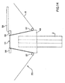
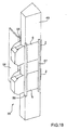
- the Figure 12-18 embodiment comprises two further movable folders 57, which move in the opposite direction to each spindle 49 to complete folding sheet 6 of wrapping into a U about spindle 49.
- each spindle 49 travels a short distance to fold sheet 6 of wrapping against fixed folders 56, and sheet 6 of wrapping is folded into a U about spindle 49 mostly by the action of movable folders 57.
- each spindle 49 is truncated-cone-shaped, tapering towards fixed folders 56. More specifically, the outlet end 51 of each tubular spindle 49 is truncated-cone-shaped, and tapers in the travelling direction of group 2 of cigarettes; and an inlet end of fixed folders 56 is truncated-cone-shaped and complementary to the truncated-cone shape of the outlet end of tubular spindle 49.
- group 2 of cigarettes is expelled from pocket 29 of input wheel 27 (not shown in Figures 12-18 ) into tubular spindle 49 by a pusher 52. As it is inserted inside tubular spindle 49, group 2 of cigarettes may be compressed laterally by the taper of the inner channel of tubular spindle 49.
- tubular spindle 49 is stationary in a withdrawn position ( Figure 12 ), and defines, with pocket 32 of wrapping wheel 30 (not shown in Figures 12-18) and at feed station 33, a gap through which a sheet 6 of wrapping is fed.
- tubular spindle 49 is moved, together with group 2 of cigarettes, towards wrapping wheel 30, so that outlet end 51 of tubular spindle 49 engages and folds sheet 6 of wrapping into a U against fixed folders 56 ( Figure 14 ).
- movable folders 57 move in the opposite direction to each spindle 49 to complete folding sheet 6 of wrapping into a U about spindle 49 ( Figures 13 and 14 ).
- group 2 of cigarettes is kept moving by pusher 52 and fed completely through spindle 49 into pocket 32 (not shown in Figures 12-18 ) together with sheet 6 of wrapping, which slides off tubular spindle 49 and wraps onto group 2 of cigarettes ( Figure 15 ).
- tubular spindle 49 returns to the withdrawn position in the opposite direction to the travelling direction of groups 2 of cigarettes, and, at the same time, a folder 58 folds one of the two flaps of the U-folded sheet 6 of wrapping onto group 2 of cigarettes ( Figure 16 ).
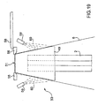
- Figure 19 shows a variation of the Figure 12-18 embodiment, in which movable folders 57 are replaced by two nozzles 59 for directing compressed-air jets 60 onto the wings of sheet 6 of wrapping on opposite sides of tubular spindle 49 to complete folding sheet 6 of wrapping into a U about spindle 49.
- the Figure 19 variation is simpler in design by substituting a fixed component (nozzles 59) for a movable component (movable folders 57) moving independently of the other components.
- sheet 6 of wrapping is engaged, not by group 2 of cigarettes, but by corresponding spindle 49, and is therefore folded into a U by spindle 49, as opposed to group 2 of cigarettes, engaging it.
- spindle 49 Only after spindle 49 has prefolded sheet 6 of wrapping is group 2 of cigarettes inserted inside the already-folded sheet 6 of wrapping.
- both ends of the cigarettes in group 2 undergo absolutely no mechanical stress when first folding sheet 6 of wrapping, thus preventing undesired deformation of both the filters and the tips of the cigarettes.
- the edges of inner package 1 are sharp and well defined, thus imparting an attractive square shape to the exposed top portion of inner package 1.
Landscapes
- Engineering & Computer Science (AREA)
- Mechanical Engineering (AREA)
- Wrapping Of Specific Fragile Articles (AREA)
- Basic Packing Technique (AREA)
Claims (14)
- Verfahren zum Herstellen einer Verpackung (1), die eine Gruppe (2) von Zigaretten enthält; wobei das Verfahren die folgenden Schritte umfasst:Befördern der Gruppe (2) von Zigaretten längs eines Weges;Befördern eines Umwicklungsbogens (6) senkrecht zu dem Weg der Gruppe (2) von Zigaretten;Befördern einer rohrförmigen Spindel (49) längs des Weges der Gruppe (2) von Zigaretten, um den Umwicklungsbogen (6) aufzufangen und um den Umwicklungsbogen (6) in ein U um die röhrenförmige Spindel (49) zu falten; undBefördern der Gruppe (2) von Zigaretten durch die rohrförmige Spindel (49), um den Umwicklungsbogen (6) von der rohrförmigen Spindel (49) herunterzuschieben und um den U-förmig gefalteten Umwicklungsbogen (6) an der Gruppe (2) von Zigaretten anzubringen;wobei das Verfahren gekennzeichnet ist durch den weiteren Schritt des Bewegens eines beweglichen Faltelements in Bezug auf die rohrförmige Spindel (49), um das Falten des Umwicklungsbogens (6) in ein U auf der rohrförmigen Spindel (49) abzuschließen.
- Verfahren nach Anspruch 1, wobei das bewegliche Faltelement zwei Falteinrichtungen (54) aufweist, die sich auf gegenüberliegenden Seiten der rohrförmigen Spindel (49) befinden und angelenkt sind, um sich um jeweilige Drehachsen (55) zu drehen.
- Verfahren nach Anspruch 1, wobei das bewegliche Faltelement zwei Falteinrichtungen (57) aufweist, die sich auf gegenüberliegenden Seiten der rohrförmigen Spindel (49) befinden und in der zur Bewegungsrichtung der Gruppe (2) von Zigaretten entgegengesetzten Richtung gleiten.
- Verfahren nach Anspruch 1, 2 oder 3, das den weiteren Schritt des Richtens von Druckluftstrahlen (60) auf die Klappen des Umwicklungsbogens (6) auf entgegengesetzten Seiten der rohrförmigen Spindel (49) umfasst, um das Falten des Umwicklungsbogens (6) in ein U auf der rohrförmigen Spindel (49) abzuschließen.
- Verfahren nach einem der Ansprüche 1 bis 4, das den weiteren Schritt des Beförderns der rohrförmigen Spindel (49) zwischen zwei festen Falteinrichtungen (46) umfasst, um das Falten des Umwicklungsbogens (6) in ein U auf der rohrförmigen Spindel (49) abzuschließen.
- Verfahren nach einem der Ansprüche 1 bis 5, das den weiteren Schritt des Beaufschlagens der rohrförmigen Spindel (49) mit einer hin und her gehenden Bewegung umfasst, die eine Vorwärtsbewegung in der Bewegungsrichtung der Gruppe (2) von Zigaretten, die die rohrförmige Spindel (49) dazu veranlasst, den Umwicklungsbogen (6) aufzufangen, und eine Rückwärtsbewegung in der zu der Bewegungsrichtung der Gruppe (6) von Zigaretten entgegengesetzten Richtung umfasst.
- Verfahren nach einem der Ansprüche 1 bis 6, wobei die rohrförmige Spindel (49) mit einer festen Falteinrichtung (50; 56) zusammenwirkt, um den Umwicklungsbogen (6) in ein U zu falten.
- Verfahren nach Anspruch 7, wobei ein Auslassende (51) der rohrförmigen Spindel (49) kegelstumpfförmig geformt ist und sich in der Bewegungsrichtung der Gruppe (2) von Zigaretten verjüngt; und ein Einlassende der festen Faltvorrichtung (50; 56) kegelstumpfförmig und komplementär zu der Kegelstumpfform des Auslassendes (51) der rohrförmigen Spindel (49) geformt ist.
- Verfahren nach einem der Ansprüche 1 bis 8, das ferner den Schritt des Beaufschlagens der Gruppe (2) von Zigaretten mit einer seitlichen Kompression, die durch die konische Form des Innenkanals der rohrförmigen Spindel (49) erzeugt wird, umfasst.
- Umwicklungseinheit für die Herstellung einer Verpackung (1), die eine Gruppe (2) von Zigaretten enthält; wobei die Umwicklungseinheit (12) umfasst:eine Beförderungsvorrichtung (52), um die Gruppe (2) von Zigaretten längs eines Weges zu befördern;eine Beförderungsstation (33), um einen Umwicklungsbogen (6) senkrecht zu dem Weg der Gruppe (2) von Zigaretten zu befördern; undeine rohrförmige Spindel (49), die längs des Weges der Gruppe (2) von Zigaretten befördert wird, um den Umwicklungsbogen (6) aufzufangen und um den Umwicklungsbogen (6) in ein U um die rohrförmige Spindel (49) zu falten;wobei die Beförderungsvorrichtung (52) die Gruppe (2) von Zigaretten durch die rohrförmige Spindel (49) befördert, um den Umwicklungsbogen (6) von der rohrförmigen Spindel (49) herunterzuschieben und um den U-förmig gefalteten Umwicklungsbogen (6) an der Gruppe (2) von Zigaretten anzubringen;wobei die Umwicklungseinheit (12) gekennzeichnet ist durch ein bewegliches Faltelement, um das Falten des Umwicklungsbogens (6) in ein U auf der rohrförmigen Spindel (49) abzuschließen.
- Umwicklungseinheit nach Anspruch 10, die Düsen (59) umfasst, die sich auf gegenüberliegenden Seiten der rohrförmigen Spindel (49) befinden, um auf die Klappen des Umwicklungsbogens (6) auf gegenüberliegenden Seiten der rohrförmigen Spindel (49) Druckluftstrahlen zu richten, um das Falten des Umwicklungsbogens (6) in ein U auf der rohrförmigen Spindel (49) abzuschließen.
- Umwicklungseinheit nach Anspruch 10, die zwei feste Falteinrichtungen (56) umfasst, die sich auf gegenüberliegenden Seiten der rohrförmigen Spindel (49) befinden und zwischen denen die rohrförmige Spindel (49) befördert wird, um das Falten des Umwicklungsbogens (6) in ein U abzuschließen.
- Umwickiungseinheit nach einem der Ansprüche 10 bis 12, wobei die rohrförmige Spindel (49) in einer hin und her gehenden Bewegung bewegt wird, die eine Vorwärtsbewegung in der Bewegungsrichtung der Gruppe (2) von Zigaretten, die die rohrförmige Spindel (49) dazu veranlasst, den Umwicklungsbogen (6) aufzufangen, und eine Rückwärtsbewegung in der zu der Bewegungsrichtung der Gruppe (2) von Zigaretten entgegengesetzten Richtung umfasst.
- Umwicklungseinheit nach einem der Ansprüche 10 bis 13, wobei eine Oberfläche der rohrförmigen Spindel (49), die mit den Umwicklungsbögen (6) in Kontakt gelangt, eine Anzahl von Löchern besitzt, die mit einer Saugquelle verbunden sind.
Applications Claiming Priority (1)
| Application Number | Priority Date | Filing Date | Title |
|---|---|---|---|
| IT000094A ITBO20080094A1 (it) | 2008-02-13 | 2008-02-13 | Metodo ed unita di incarto per ripiegare un foglio di incarto attorno ad un gruppo di sigarette. |
Publications (2)
| Publication Number | Publication Date |
|---|---|
| EP2090511A1 EP2090511A1 (de) | 2009-08-19 |
| EP2090511B1 true EP2090511B1 (de) | 2010-10-13 |
Family
ID=40291416
Family Applications (1)
| Application Number | Title | Priority Date | Filing Date |
|---|---|---|---|
| EP09152615A Active EP2090511B1 (de) | 2008-02-13 | 2009-02-11 | Verfahren und Wickeleinheit zum Falten eines Bogens zum Umwickeln eines Zigarettenbündels |
Country Status (5)
| Country | Link |
|---|---|
| US (1) | US7900424B2 (de) |
| EP (1) | EP2090511B1 (de) |
| JP (1) | JP5497305B2 (de) |
| DE (1) | DE602009000261D1 (de) |
| IT (1) | ITBO20080094A1 (de) |
Families Citing this family (7)
| Publication number | Priority date | Publication date | Assignee | Title |
|---|---|---|---|---|
| IT1394894B1 (it) * | 2009-04-17 | 2012-07-20 | Gima Spa | Dispositivo per il confezionamento di un prodotto in un involucro |
| US8046978B2 (en) * | 2009-10-02 | 2011-11-01 | R.J. Reynolds Tobacco Company | Equipment and method for packaging multiple packets of cigarettes |
| DE102009060134A1 (de) | 2009-12-09 | 2011-06-16 | Focke & Co.(Gmbh & Co. Kg) | Packungen insbesondere für Zigaretten sowie Verfahren und Vorrichtung zum Herstellen derselben |
| WO2014002166A1 (ja) * | 2012-06-25 | 2014-01-03 | 日本たばこ産業株式会社 | 棒状喫煙物品用パッケージの製造方法、棒状喫煙物品用パッケージ、及び棒状喫煙物品用パッケージの製造装置 |
| ES2612337T3 (es) * | 2012-09-04 | 2017-05-16 | Frederik Bergwerff | Método para envasar productos de tabaco acabados, en una caja maestra |
| DE102012019909A1 (de) * | 2012-10-11 | 2014-04-17 | Theegarten-Pactec Gmbh & Co. Kg | Hochleistungs-Verpackungsverfahren zur Verpackung von, insbesondere kleinstückigen, Produkten und Hochleistungs-Verpackungseinrichtung, insbesondere zur Durchführung des Verfahrens |
| ITUA20161853A1 (it) | 2016-03-21 | 2017-09-21 | Gd Spa | Unità e metodo di incarto per piegare un foglio di incarto attorno ad un articolo |
Family Cites Families (11)
| Publication number | Priority date | Publication date | Assignee | Title |
|---|---|---|---|---|
| FR748575A (de) * | 1933-07-05 | |||
| US1647265A (en) * | 1926-04-07 | 1927-11-01 | American Mach & Foundry | Feeding device for cigarette-packaging machines |
| US3412520A (en) * | 1964-08-10 | 1968-11-26 | Schmermund Alfred | Methods of wrapping block-like articles |
| IT1023644B (it) * | 1974-12-13 | 1978-05-30 | Wrapmatic Spa | Apparecchiatura per l avvogimento li risme di carta e simili con fogli tagliati da un nastro di imballaggio e per regolare le dimensioni dei fogli al formato delle risme |
| IT1089586B (it) * | 1977-11-30 | 1985-06-18 | Amf Sasib | Un perfezionamento alle macchine impacchettatrici di sigarette |
| DE3348487C2 (de) * | 1983-09-14 | 1998-05-20 | Focke & Co | Vorrichtung zum Herstellen von Großpackungen |
| IT1238296B (it) * | 1990-04-02 | 1993-07-12 | Gd Spa | Metodo ed impianto per il sovraincarto di pacchetti. |
| IT1290696B1 (it) * | 1997-02-24 | 1998-12-10 | Gd Spa | Metodo e macchina per l'incarto di prodotti. |
| EP1216923B1 (de) * | 2000-12-20 | 2006-03-15 | Tissue Machinery Company S.p.A. | Verfahren und Vorrichtung zum Verpacken von Stapeln von Papier oder dergleichen in einer Umhüllungsfolie |
| ITBO20050275A1 (it) * | 2005-04-22 | 2005-07-22 | Gd Spa | Macchina sovraincartatrice per pacchetti di sigarette |
| EP1854724B1 (de) * | 2006-05-09 | 2012-07-11 | G.D Società Per Azioni | Verfahren und Maschine zum Herstellen von Zigarettenpackungen |
-
2008
- 2008-02-13 IT IT000094A patent/ITBO20080094A1/it unknown
-
2009
- 2009-02-11 DE DE602009000261T patent/DE602009000261D1/de active Active
- 2009-02-11 EP EP09152615A patent/EP2090511B1/de active Active
- 2009-02-11 US US12/369,235 patent/US7900424B2/en active Active
- 2009-02-13 JP JP2009031769A patent/JP5497305B2/ja not_active Expired - Fee Related
Also Published As
| Publication number | Publication date |
|---|---|
| JP5497305B2 (ja) | 2014-05-21 |
| JP2009190792A (ja) | 2009-08-27 |
| EP2090511A1 (de) | 2009-08-19 |
| DE602009000261D1 (de) | 2010-11-25 |
| US20090199515A1 (en) | 2009-08-13 |
| US7900424B2 (en) | 2011-03-08 |
| ITBO20080094A1 (it) | 2008-05-14 |
Similar Documents
| Publication | Publication Date | Title |
|---|---|---|
| EP2716555B1 (de) | Wickelverfahren und -einheit zum Falten eines Bogens aus Material zum Umwickeln eines Zigarettenbündels | |
| EP2090511B1 (de) | Verfahren und Wickeleinheit zum Falten eines Bogens zum Umwickeln eines Zigarettenbündels | |
| EP2435314B1 (de) | Wickelverfahren und -einheit zum falten eines bogens aus material zum umwickeln eines zigarettenbündels | |
| US7240469B2 (en) | Cigarette packing machine for producing rigid hinged-lid packets | |
| EP2874887B1 (de) | Verpackungsverfahren und maschine zur herstellung einer versiegelten packung mit einer gruppe von tabakartikeln | |
| WO2014013479A2 (en) | Package of tobacco articles comprising a sealed inner package | |
| WO2015128812A1 (en) | Packing method and unit for folding a sheet of packing material around a parallelepipedal product | |
| US8266877B2 (en) | Packing method and unit for folding a sheet of packing material about a parallelepiped-shaped article | |
| GB2448816A (en) | Packing cigarettes in slide-open packets | |
| EP2620375B1 (de) | Verpackungsmaschine zur Herstellung einer Packung für Rauchartikel mit Schiebeöffnung | |
| EP2620373B1 (de) | Verpackungsmaschine und Verfahren zur Herstellung einer Packung für Rauchartikel mit Scharnierdeckel und Schiebeöffnung | |
| US8925288B2 (en) | Packing method and unit for folding a sheet of packing material about an article such as a group of cigarettes | |
| CN112292327B (zh) | 抽拉件、相关供给方法及用于吸烟制品的包装机 | |
| EP2620374B1 (de) | Verpackungsverfahren und Einheit zur Herstellung eines Außenbehälters einer Packung für Rauchartikel mit Scharnierdeckel und Schiebeöffnung | |
| EP2620372B1 (de) | Verpackungsverfahren mit nicht trockenem, mehrmals verwendbarem Klebstoff |
Legal Events
| Date | Code | Title | Description |
|---|---|---|---|
| PUAI | Public reference made under article 153(3) epc to a published international application that has entered the european phase |
Free format text: ORIGINAL CODE: 0009012 |
|
| AK | Designated contracting states |
Kind code of ref document: A1 Designated state(s): AT BE BG CH CY CZ DE DK EE ES FI FR GB GR HR HU IE IS IT LI LT LU LV MC MK MT NL NO PL PT RO SE SI SK TR |
|
| AX | Request for extension of the european patent |
Extension state: AL BA RS |
|
| 17P | Request for examination filed |
Effective date: 20091126 |
|
| GRAP | Despatch of communication of intention to grant a patent |
Free format text: ORIGINAL CODE: EPIDOSNIGR1 |
|
| AKX | Designation fees paid |
Designated state(s): CH DE GB LI TR |
|
| RIN1 | Information on inventor provided before grant (corrected) |
Inventor name: BIONDI, ANDREA Inventor name: DAKESSIAN, CRISTIAN Inventor name: BERTUZZI, IVANOE Inventor name: VITALI, ANTONIO Inventor name: TESTONI, LUCA |
|
| GRAS | Grant fee paid |
Free format text: ORIGINAL CODE: EPIDOSNIGR3 |
|
| GRAA | (expected) grant |
Free format text: ORIGINAL CODE: 0009210 |
|
| AK | Designated contracting states |
Kind code of ref document: B1 Designated state(s): CH DE GB LI TR |
|
| REG | Reference to a national code |
Ref country code: GB Ref legal event code: FG4D |
|
| REG | Reference to a national code |
Ref country code: CH Ref legal event code: EP |
|
| REF | Corresponds to: |
Ref document number: 602009000261 Country of ref document: DE Date of ref document: 20101125 Kind code of ref document: P |
|
| PLBE | No opposition filed within time limit |
Free format text: ORIGINAL CODE: 0009261 |
|
| STAA | Information on the status of an ep patent application or granted ep patent |
Free format text: STATUS: NO OPPOSITION FILED WITHIN TIME LIMIT |
|
| 26N | No opposition filed |
Effective date: 20110714 |
|
| REG | Reference to a national code |
Ref country code: DE Ref legal event code: R097 Ref document number: 602009000261 Country of ref document: DE Effective date: 20110714 |
|
| PG25 | Lapsed in a contracting state [announced via postgrant information from national office to epo] |
Ref country code: TR Free format text: LAPSE BECAUSE OF FAILURE TO SUBMIT A TRANSLATION OF THE DESCRIPTION OR TO PAY THE FEE WITHIN THE PRESCRIBED TIME-LIMIT Effective date: 20101013 |
|
| REG | Reference to a national code |
Ref country code: CH Ref legal event code: PL |
|
| PG25 | Lapsed in a contracting state [announced via postgrant information from national office to epo] |
Ref country code: LI Free format text: LAPSE BECAUSE OF NON-PAYMENT OF DUE FEES Effective date: 20130228 Ref country code: CH Free format text: LAPSE BECAUSE OF NON-PAYMENT OF DUE FEES Effective date: 20130228 |
|
| PGFP | Annual fee paid to national office [announced via postgrant information from national office to epo] |
Ref country code: GB Payment date: 20160226 Year of fee payment: 8 |
|
| GBPC | Gb: european patent ceased through non-payment of renewal fee |
Effective date: 20170211 |
|
| PG25 | Lapsed in a contracting state [announced via postgrant information from national office to epo] |
Ref country code: GB Free format text: LAPSE BECAUSE OF NON-PAYMENT OF DUE FEES Effective date: 20170211 |
|
| PGFP | Annual fee paid to national office [announced via postgrant information from national office to epo] |
Ref country code: DE Payment date: 20240228 Year of fee payment: 16 |