EP2090460A1 - Siège doté d'un système de détection de l'occupation - Google Patents
Siège doté d'un système de détection de l'occupation Download PDFInfo
- Publication number
- EP2090460A1 EP2090460A1 EP08151382A EP08151382A EP2090460A1 EP 2090460 A1 EP2090460 A1 EP 2090460A1 EP 08151382 A EP08151382 A EP 08151382A EP 08151382 A EP08151382 A EP 08151382A EP 2090460 A1 EP2090460 A1 EP 2090460A1
- Authority
- EP
- European Patent Office
- Prior art keywords
- seat
- detection system
- reference capacitor
- electrode
- occupancy detection
- Prior art date
- Legal status (The legal status is an assumption and is not a legal conclusion. Google has not performed a legal analysis and makes no representation as to the accuracy of the status listed.)
- Withdrawn
Links
- 239000003990 capacitor Substances 0.000 claims abstract description 73
- 238000001514 detection method Methods 0.000 claims abstract description 39
- 238000011156 evaluation Methods 0.000 claims abstract description 39
- 238000007599 discharging Methods 0.000 claims description 11
- 230000005684 electric field Effects 0.000 description 10
- 230000001960 triggered effect Effects 0.000 description 6
- 230000008859 change Effects 0.000 description 4
- 238000001228 spectrum Methods 0.000 description 4
- 230000008878 coupling Effects 0.000 description 3
- 238000010168 coupling process Methods 0.000 description 3
- 238000005859 coupling reaction Methods 0.000 description 3
- 230000007423 decrease Effects 0.000 description 3
- 230000010354 integration Effects 0.000 description 3
- 238000009825 accumulation Methods 0.000 description 2
- 210000000038 chest Anatomy 0.000 description 2
- 238000010586 diagram Methods 0.000 description 2
- 238000006073 displacement reaction Methods 0.000 description 2
- 230000036039 immunity Effects 0.000 description 2
- 230000000737 periodic effect Effects 0.000 description 2
- 230000035945 sensitivity Effects 0.000 description 2
- 230000001360 synchronised effect Effects 0.000 description 2
- 210000000689 upper leg Anatomy 0.000 description 2
- 238000010276 construction Methods 0.000 description 1
- 239000007788 liquid Substances 0.000 description 1
- 238000005259 measurement Methods 0.000 description 1
- 230000007246 mechanism Effects 0.000 description 1
- 230000037361 pathway Effects 0.000 description 1
- 230000003252 repetitive effect Effects 0.000 description 1
- XLYOFNOQVPJJNP-UHFFFAOYSA-N water Substances O XLYOFNOQVPJJNP-UHFFFAOYSA-N 0.000 description 1
Images

Classifications
-
- B—PERFORMING OPERATIONS; TRANSPORTING
- B60—VEHICLES IN GENERAL
- B60N—SEATS SPECIALLY ADAPTED FOR VEHICLES; VEHICLE PASSENGER ACCOMMODATION NOT OTHERWISE PROVIDED FOR
- B60N2/00—Seats specially adapted for vehicles; Arrangement or mounting of seats in vehicles
- B60N2/002—Seats provided with an occupancy detection means mounted therein or thereon
-
- B—PERFORMING OPERATIONS; TRANSPORTING
- B60—VEHICLES IN GENERAL
- B60R—VEHICLES, VEHICLE FITTINGS, OR VEHICLE PARTS, NOT OTHERWISE PROVIDED FOR
- B60R21/00—Arrangements or fittings on vehicles for protecting or preventing injuries to occupants or pedestrians in case of accidents or other traffic risks
- B60R21/01—Electrical circuits for triggering passive safety arrangements, e.g. airbags, safety belt tighteners, in case of vehicle accidents or impending vehicle accidents
- B60R21/015—Electrical circuits for triggering passive safety arrangements, e.g. airbags, safety belt tighteners, in case of vehicle accidents or impending vehicle accidents including means for detecting the presence or position of passengers, passenger seats or child seats, and the related safety parameters therefor, e.g. speed or timing of airbag inflation in relation to occupant position or seat belt use
- B60R21/01512—Passenger detection systems
- B60R21/0153—Passenger detection systems using field detection presence sensors
- B60R21/01532—Passenger detection systems using field detection presence sensors using electric or capacitive field sensors
Definitions
- the present invention generally relates to the detection of the occupancy state of a seat, in particular using a capacitive detection system.
- the present invention may e.g. be used in an automotive vehicle in order to detect the occupancy status of one or more vehicle seats.
- the present invention may also be used in other non-automotive applications, in which the occupancy status of a seat or the like may be of interest.
- a capacitive occupant detection system refers to a capacitive sensor adapted for detecting the occupancy state of a seat.
- a capacitive sensor also called electric field sensor or proximity sensor, designates a sensor, which generates a signal responsive to the influence of what is being sensed (a person, a part of a person's body, a pet, an object, etc.) upon an electric field.
- a capacitive sensor generally comprises at least one electrode, to which is applied an oscillating electric signal and which thereupon emits an electric field into a region of space proximate to the electrode, while the sensor is operating.
- the sensor comprises at least one sensing electrode - which could comprise the same electrode or electrodes, to which the oscillating electric signal is applied - at which the influence of an object or living being on the electric field is detected.
- the object to be sensed modifies the capacitance between the transmit electrode and ground.
- the transmit electrode In the "shunt mode", an oscillating voltage signal is applied to the transmit electrode, building up an electric field to a receive electrode, and the displacement current induced at the receive electrode is measured, whereby the displacement current may be modified by the body being sensed.
- the transmit electrode In the "transmit mode”, the transmit electrode is put in contact with the user's body, which then becomes a transmitter relative to a receiver, either by direct electrical connection or via capacitive coupling.
- “Shunt mode” is alternatively referred to as "coupling mode”.
- Capacitive occupant sensing systems have been proposed in great variety, e.g. for controlling the deployment of one or more airbags, such as e.g. a driver airbag, a passenger airbag and/or a side airbag.
- US patent 6,161,070, to Jinno et al. relates to a passenger detection system including a single antenna electrode mounted on a surface of a passenger seat in an automobile. An oscillator applies on periodic oscillating voltage signal to the antenna electrode, whereby a minute electric field is produced around the antenna electrode.
- Jinno proposes detecting the presence or absence of a passenger in the seat based on the amplitude and the phase of the current flowing to the antenna electrode.
- the present invention proposes a seat including a seating portion and a backrest and an occupancy detection system associated to said seat.
- the occupancy detection system comprises at least one sensing electrode arranged in said seating portion or said backrest and a control and evaluation circuit operatively coupled to said sensing electrode, said control and evaluation circuit for determining a parameter indicative of the capacitance of said sensing electrode with respect to the surroundings of said electrode, said capacitance being responsive to the presence of absence of an occupant sitting on the seat.
- said control and evaluation circuit comprises a voltage supply for providing a predetermined supply voltage, at least one reference capacitor having a first terminal and a second terminal, said first terminal being operatively coupled to ground potential; a controlled switching arrangement, said switching arrangement being arranged for connecting the at least one electrode alternately to said voltage supply and to the second terminal of said reference capacitor, and an evaluation unit configured and arranged for determining a parameter representative of the charging behaviour of the reference capacitor.
- the capacitance of the at least one sensing electrode is determined by the repeated charging of the capacitance C X to be determined to the supply voltage V S and the subsequent discharging to the reference capacitor C REF .
- the switching operation arrangement is operated in such a manner, that the reference capacitor is never directly connected to the supply voltage V S .
- this charge Q X is partially transferred to the reference capacitor, the portion of the charge to be transferred depending on the value of capacitance C X .
- the voltage at the second terminal of the reference capacitor increases by an amount, which is depending on the quantity of charge transferred and thus again on the value of the capacitance C X to be determined. It follows that the charging behaviour of the reference capacitor is directly influenced by the capacitance C X to be determined; a larger capacitance C X resulting in a faster charging of the reference capacitor. It follows that by determining a parameter, which is representative of the charging behaviour of the reference capacitor, the occupancy detection system will be able to distinguish between an empty seat and a seat occupied by a person.
- the parameter representative of the charging behaviour of the reference capacitor may e.g. be the number of switching cycles of said controlled switching arrangement which is required in order to charge said reference capacitor to a predetermined threshold voltage. In this case, the above-described operation is repeated until the voltage at the second terminal of the reference capacitor is equal to the predetermined threshold voltage. It will be easily verified by the skilled person, that the number of switching cycles, which is required for the voltage at the second terminal of the reference capacitor to reach the threshold voltage is depending on the value of the capacitance to be determined and may thus be used by a processor unit for determining the capacitance of the sensing electrode or for discriminating between an occupied seat and an empty seat.
- Another parameter representative of the charging behaviour of the reference capacitor may be the rate at which the voltage at the second terminal of the reference capacitor increases or the voltage at the second terminal of the reference capacitor after a specific number of switching cycles or after a specific time period.
- the present invention In contrast to the state of the art capacitive occupancy detectors, in which the capacitive coupling of an antenna electrode to a passenger is directly determined by measuring the current flowing into the electrode, the present invention relies upon a repetitive transfer of charges between the capacitance to be determined and a known reference capacitance. Due to this repeated charge transfer, the system of the present invention is able to detect very small capacitance variations with sufficient accuracy using very simple and consequently low cost evaluation circuitry. As a result, the present invention enables detection of seat occupancy with sensing electrodes having a substantially reduced dimension when compared to the classical capacitive detection systems, in which the electrode antennas preferably covered the entire seating surface of the seat.
- the present invention thus enables the use of very small sensing electrodes, which can be easily integrated into the seat cushion or the backrest without impairing the comfort of the seat for the occupant.
- the present invention thus provides for a very low cost capacitive detection system, which furthermore makes integration into the seat much easier.
- control and evaluation circuit can easily be arranged and integrated into the seat. It will however be understood that this control and evaluation circuit may also be arranged at any suitable location outside the seat.
- said evaluation unit comprises at least one comparator, said comparator for comparing the voltage at the second terminal of said reference capacitor with said predetermined threshold voltage and for issuing a signal indicative of the result of said comparison.
- the comparator toggles and this change in the comparator output may trigger i.a. the determination of the capacitance value in an associated decision circuit.
- the evaluation unit further comprises a delay block, which is controlled by a clocked signal, and which is operatively connected at the output of the comparator.
- a delay block is an electronic circuit element, which may change its output state only if the clocked signal at a corresponding clock input changes. Accordingly, if the input data signal changes e.g. from "high” to "low", the delay block maintains its output state until the next change in the clock signal and thus operates as a latch.
- the delay block makes comparator operation synchronized to the clock signal and thus triggers i.a. the determination of the capacitance value or the occupancy state in the associated decision circuit.
- control and evaluation circuit further comprises circuit elements for the controlled discharging of said reference capacitor.
- circuit elements may e.g. comprise a series arrangement of a resistor and a controlled switch which is connected across the reference capacitor.
- the switch may e.g. be controlled by the comparator or an associated electronic circuit to close after the voltage V CREF at the second terminal of the reference capacitor C REF has reached the comparator reference voltage V REF . The voltage on the reference capacitor thus decreases and another detection cycle may restart.
- the controlled switch for discharging the reference capacitor is controlled by the delay block connected to the output of the comparator.
- the switch is controlled to close after the voltage V CREF at the second terminal of the reference capacitor C REF has exceeded the comparator reference voltage V REF and the delay block has been triggered by the corresponding clock signal. After the switch is closed, the voltage on the reference capacitor decreases until it has fallen below the comparator reference voltage V REF and the delay block has been triggered by the corresponding clock signal.
- the controlling of the discharge switch by the delay block which itself is controlled by a preferably low frequency clock signal, thus limits the minimum discharge switch on/off time.
- the discharge switch is not immediately closed after the voltage V CREF at the second terminal of the reference capacitor C REF reaches the comparator reference voltage V REF but only after the subsequent clock pulse of the delay block clock, which triggers the delay block to invert its output.
- the voltage V CREF at the second terminal of the reference capacitor C REF continues to increase due to the continued operation of the controlled switching arrangement.
- the delay block is triggered and the discharge switch is closed, the voltage at the second terminal of the reference capacitor C REF thus has reached a maximum value V CREF,max , which depends on the charging behaviour of the reference capacitor and thus on the capacitance C X to be determined.
- the voltage at the reference capacitor increases faster for larger capacitance C X , so that V CREF,max is larger for a high capacitance C X .
- the time required for the reference capacitor to discharge to such an extend, that the voltage the second terminal of the reference capacitor C REF falls below the comparator reference voltage V REF is increased compared to the corresponding discharge time for small capacitance C X .
- the overall discharge time i.e. the time interval between the closing of the discharge switch and the subsequent opening of the discharge switch, which corresponds to the time interval, during which the delay block output is "high
- the overall discharge time i.e. the time interval between the closing of the discharge switch and the subsequent opening of the discharge switch, which corresponds to the time interval, during which the delay block output is "high
- the length of the overall discharge operation may be used as parameter for the discrimination between an empty seat and an occupied seat.
- the time interval between two discharge operations is short since after the opening of the discharge switch, the voltage at the second terminal increases rapidly due to the operation of the controlled switching arrangement.
- the parameter used for the discrimination of occupancy is the ratio between the length of the discharging intervals and length of the charging interval, which is directly obtained by the duty cycle of the delay block output signal.
- the controlled switching arrangement comprises at least one pseudo-random sequence generator, said pseudo-random sequence generator for generating a pseudo-random sequence for controlling the switching operation of said controlled switching arrangement.
- the controlled switching operation does not operate at a fixed period clock source but at pseudo-random time intervals.
- the pseudo-random sequence generator provides spread-spectrum operation and ensures good immunity from external noise sources.
- designs with the spread-spectrum clock have lower electromagnetic emission levels, which substantially reduces the above mentioned problems for EMC/EMI of the detection system.
- said at least one sensing electrode is therefore a wire-based sensing electrode, i.e. said sensing electrode comprises of a simple electrode wire, which is connected to the control and evaluation circuit. Due to the reduced dimensions of the sensing electrode and the high sensitivity of the system, the at least one sensing electrode may be easily integrated at different locations into the seat. In a possible embodiment, the at least one sensing electrode may e.g. be integrated into the seating portion below the seating surface of the seat. This is the classical integration location for capacitive antenna electrodes.
- the reduced size sensing electrode of the present invention may be more specifically arranged in a location, in which a detection of a human occupant is more reliable.
- a wire-based sensing electrode might e.g. be integrated in traverse direction in the front part of the seating surface.
- the occupancy sensor will be particularly sensitive to the thighs of an occupant sitting on the seat.
- said at least one sensing electrode is arranged in said backrest of said seat, preferably in an upper portion of the backrest. In this location, the detection system is particularly sensitive to the thorax of an occupant, while being less sensitive to water or other liquids spilled on the seat or metallic objects placed onto the seat.
- the occupancy detection system comprises at least one guard electrode, said at least one guard electrode being associated to said at least one sensing electrode, said at least one guard electrode being operatively coupled to the control and evaluation circuit.
- the guard electrode may e.g. be a sheet like electrode which is arranged behind the sensing electrode and which is operated in parallel to the sensing electrode by the control and evaluation unit. Additionally or alternatively a seat frame of said seat or a seat heater integrated in said seating portion or in said backrest of said seat is operatively coupled to the control and evaluation circuit so as to operate as guard electrode.
- the sensitivity of the system may be delimited to the interesting region in front of the backrest and above the seating portion, thereby excluding the risk of false positives caused e.g. by a passenger sitting on a rear seat.
- the seat frame of said seat or the seat heater integrated in said seating portion or in said backrest is operatively coupled to ground potential so as to operate as shield electrode.
- the present invention finds its application e.g. in automotive vehicles, where the information regarding the occupancy of the vehicle seats may be used in a seat belt reminder system of in the control of the secondary restraint systems such of the vehicle as the vehicle airbags or seat belt pretensionners, etc.
- the system of the present invention may e.g. be used in cinemas, theatres, sports stadiums or the like in order to monitor the distribution of seat occupancy and available places.
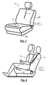
- Fig. 1 shows a perspective view of a vehicle seat 10 with associated capacitive occupancy detection system
- Fig. 2 shows a side view of the same seat with a person sitting in the seat.
- the seat 10 comprises a seating portion 12 and a backrest 14, which are both equipped with sensing electrodes 16 and 18 of a capacitive occupancy sensing system.
- Both sensing electrodes 16 and 18 are preferably wire-based electrodes, i.e. the sensing electrodes preferably consist of a simple conductive wire.
- Electrode 16 is arranged in an upper portion of the backrest 14, where is sensitive to the thorax of a person 20 all the while being less sensitive to small objects placed on the seating surface 22 of the seating portion 12.
- electrode 18 is arranged in transverse direction in a front portion of the seating portion. In this location, electrode 18 is sensitive to the thighs of the person 20.
- Both electrodes 16 and 18 are schematically represented to be connected to a control and evaluation circuit 24.
- the control and evaluation circuit 24 is schematically represented to be located outside the seat in Figs 1 and 2 . It is however to be noted, that the control and evaluation circuit 24 can be arranged in the seat 10 or at any other suitable location outside the seat.
- the control and evaluation circuit 24 is configured and operatively connected to the electrodes 16 and 18 for determining a parameter representative of the capacitance C X of the electrode, the value of which is depending on the presence or the absence of a passenger 20 on the seat and in the detection range of the sensing system.
- the control and evaluation circuit 24 comprises a voltage supply for providing a predetermined supply voltage V S , at least one reference capacitor C REF of known capacitance, a first terminal of which being operatively coupled to ground potential GND.
- a controlled switching arrangement comprising switches S 1 and S 2 is provided and arranged for connecting the electrode 16 or 18 alternately to said voltage supply V S by means of switch S 1 and to the second terminal of said reference capacitor C REF by means of switch S 2 .
- the arrangement and the control of the switches S 1 and S 2 is such that at any time during the operation, at least one of the switches S 1 and S 2 is open.
- an evaluation unit 26 is configured and arranged for determining a parameter representative of the charging behaviour of the reference capacitor. It follows that the charging behaviour of the reference capacitor is directly influenced by the capacitance C X to be determined; a larger capacitance C X resulting in a faster charging of the reference capacitor. It follows that by determining a parameter, which is representative of the charging behaviour of the reference capacitor, the occupancy detection system will be able to distinguish between an empty seat and a seat occupied by a person..
- the capacitance C X of electrode 16 or 18 is determined by the repeated charging of the capacitance C X to the supply voltage V S and the subsequent discharging to the reference capacitor C REF .
- the switches S 1 and S 2 are operated in such a manner, that the reference capacitor C REF is never directly connected to the supply voltage V S .
- this charge Q X is partially transferred to the reference capacitor, the portion of the charge to be transferred depending on the value of capacitance C X .
- the voltage at the second terminal of the reference capacitor increases by an amount which is depending on the quantity of charge transferred and thus again on the value of the capacitance C X to be determined. This operation is repeated until the voltage at the second terminal of the reference capacitor C REF is equal to the predetermined threshold voltage V REF . It will be easily verified by the skilled person, that the number of switching cycles, which is required for the voltage at the second terminal of the reference capacitor to reach the threshold voltage is depending on the value of the capacitance to be determined and may thus be used by a processor unit for determining the capacitance of the electrode or for discriminating between an occupied seat and an empty seat.
- other parameters representative of the charging behaviour of the reference capacitor may be the rate at which the voltage at the second terminal of the reference capacitor increases or the voltage at the second terminal of the reference capacitor after a specific number of switching cycles or after a specific time period.
- the parameter used for the discrimination of occupancy is the ratio between the length of the discharging intervals and length of the charging interval, which is directly obtained by the duty cycle of the delay block output signal.
- the evaluation unit 26 preferably comprises at least one comparator COMP for comparing the voltage at the second terminal of said reference capacitor C REF with said predetermined threshold voltage and for issuing a signal indicative of the result of said comparison.
- the comparator toggles and this change in the comparator output may trigger i.a. the determination of the capacitance value in an associated decision circuit 28.
- control and evaluation circuit 24 further comprises circuit elements for the controlled discharging of said reference capacitor.
- these circuit elements comprise a series arrangement of a resistor R and a controlled switch S 3 which is connected across the reference capacitor C REF .
- the switch S 3 may e.g. be controlled by the comparator or as shown by the associated electronic circuit 28.
- Electronic circuit 28 preferably comprises a delay block 30, which is controlled by a clocked signal from clock 32, and which is operatively connected at the output of the comparator COMP.
- the delay block 30 makes comparator operation synchronized to the clock signal and thus triggers i.a. the determination of the capacitance value or the occupancy state in the associated decision circuit.
- the controlled switch S 3 for discharging the reference capacitor C REF is controlled by the delay block 30 connected to the output of the comparator COMP.
- the switch S 3 is thus controlled to close after the voltage V CREF at the second terminal of the reference capacitor C REF has exceeded the comparator reference voltage V REF and the delay block 30 has been triggered by the corresponding clock signal. After the switch is closed, the voltage on the reference capacitor decreases until it has fallen below the comparator reference voltage V REF and the delay block 30 has been triggered by the corresponding clock signal.
- the controlling of the discharge switch S 3 by the delay block 30, which itself is controlled by a preferably low frequency clock signal, thus limits the minimum discharge switch on/off time.
- the discharge switch S 3 is not immediately closed after the voltage V CREF at the reference capacitor C REF reaches the comparator reference voltage V REF but only after the subsequent clock pulse of the delay block clock 32, which triggers the delay block 30 to invert its output.
- the voltage V CREF at the second terminal of the reference capacitor C REF continues to increase due to the continued operation of the controlled switching arrangement.
- the delay block is triggered and the discharge switch is closed, the voltage at the second terminal of the reference capacitor C REF thus has reached a maximum value V CREF,max , which depends on the charging behaviour of the reference capacitor and thus on the capacitance C X to be determined.
- the preferred parameter used for the discrimination of occupancy is the ratio between the length of the discharging intervals and length of the charging interval, which is directly obtained by the duty cycle of the delay block output signal.
- the controlled switching arrangement comprises at least one pseudo-random sequence generator PRS 34 for generating a pseudo-random sequence for controlling the switching operation of the switches S 1 and S 2 .
- the controlled switching operation therefore does not operate at a fixed period clock source but at pseudo-random time intervals.
- the pseudo-random sequence generator provides spread-spectrum operation and ensures good immunity from external noise sources.
- designs with the spread-spectrum clock have lower electromagnetic emission levels, which substantially reduces the above mentioned problems for EMC/EMI of the detection system.
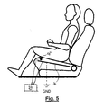
- Fig. 4 and 5 schematically illustrate embodiments of the invention, in which a seat frame or chassis 36 or a seat heater 36 integrated in said seating portion or in said backrest is operatively coupled to the control and evaluation circuit 24 so as to operate as guard electrode.
- the seat frame or chassis 36 or a seat heater 36 could also be operatively connected to ground potential and thus operate as a shielding electrode. This is schematically represented by the dashed connection to ground.
- the elements denoted with reference numeral 36 could also be a dedicated guard electrode, which is associated to hte sensing electrode 16 or 18, and which is operatively coupled to the control and evaluation circuit 24.
Priority Applications (2)
| Application Number | Priority Date | Filing Date | Title |
|---|---|---|---|
| EP08151382A EP2090460A1 (fr) | 2008-02-13 | 2008-02-13 | Siège doté d'un système de détection de l'occupation |
| PCT/EP2009/050860 WO2009100980A1 (fr) | 2008-02-13 | 2009-01-26 | Siège à système de détection d'occupation |
Applications Claiming Priority (1)
| Application Number | Priority Date | Filing Date | Title |
|---|---|---|---|
| EP08151382A EP2090460A1 (fr) | 2008-02-13 | 2008-02-13 | Siège doté d'un système de détection de l'occupation |
Publications (1)
| Publication Number | Publication Date |
|---|---|
| EP2090460A1 true EP2090460A1 (fr) | 2009-08-19 |
Family
ID=39705206
Family Applications (1)
| Application Number | Title | Priority Date | Filing Date |
|---|---|---|---|
| EP08151382A Withdrawn EP2090460A1 (fr) | 2008-02-13 | 2008-02-13 | Siège doté d'un système de détection de l'occupation |
Country Status (2)
| Country | Link |
|---|---|
| EP (1) | EP2090460A1 (fr) |
| WO (1) | WO2009100980A1 (fr) |
Cited By (7)
| Publication number | Priority date | Publication date | Assignee | Title |
|---|---|---|---|---|
| EP2368771A1 (fr) * | 2010-03-25 | 2011-09-28 | Iee International Electronics & Engineering S.A. | Combinaison de chauffage pour siège et de capteur de présence capacitif |
| LU91739B1 (en) * | 2010-09-23 | 2012-03-26 | Iee Sarl | Capacitive occupant detection system |
| GB2507740A (en) * | 2012-11-07 | 2014-05-14 | Trainfx Ltd | A passenger vehicle seat with occupancy detection and validation sensors |
| US9000331B2 (en) | 2011-09-21 | 2015-04-07 | Iee International Electronics & Engineering S.A. | Capacitive sensing system able of using heating element as antenna electrode |
| US9006618B2 (en) | 2010-03-25 | 2015-04-14 | Iee International Electronics & Engineering S.A. | Combined seat heater and capacitive occupancy sensor |
| US9132850B2 (en) | 2011-09-21 | 2015-09-15 | Iee International Electronics & Engineering S.A. | Capacitive sensing system configured for using heating element as antenna electrode |
| DE102012025037C5 (de) * | 2012-12-20 | 2017-10-26 | I.G. Bauerhin Gmbh | Verfahren zur kapazitiven Sitzbelegungserkennung für Fahrzeugsitze |
Citations (6)
| Publication number | Priority date | Publication date | Assignee | Title |
|---|---|---|---|---|
| US4796013A (en) * | 1985-10-18 | 1989-01-03 | Aisin Seiki Kabushiki Kaisha | Capacitive occupancy detector apparatus |
| EP0976625A2 (fr) * | 1998-07-28 | 2000-02-02 | Nec Corporation | Système de détection de passager et système airbag l 'utilisant |
| US6161070A (en) | 1996-02-23 | 2000-12-12 | Nec Home Electronics, Inc. | Passenger detection system |
| US6445294B1 (en) * | 1999-07-15 | 2002-09-03 | Automotive Systems Laboratory, Inc. | Proximity sensor |
| US6577023B1 (en) * | 1998-12-30 | 2003-06-10 | Automotive Systems Laboratory, Inc. | Occupant detection system |
| EP1839962A1 (fr) * | 2005-10-12 | 2007-10-03 | Elesys North America Inc. | Capteur d'occupant et procédé de ceinture de sécurité ou autre surveillance |
-
2008
- 2008-02-13 EP EP08151382A patent/EP2090460A1/fr not_active Withdrawn
-
2009
- 2009-01-26 WO PCT/EP2009/050860 patent/WO2009100980A1/fr active Application Filing
Patent Citations (6)
| Publication number | Priority date | Publication date | Assignee | Title |
|---|---|---|---|---|
| US4796013A (en) * | 1985-10-18 | 1989-01-03 | Aisin Seiki Kabushiki Kaisha | Capacitive occupancy detector apparatus |
| US6161070A (en) | 1996-02-23 | 2000-12-12 | Nec Home Electronics, Inc. | Passenger detection system |
| EP0976625A2 (fr) * | 1998-07-28 | 2000-02-02 | Nec Corporation | Système de détection de passager et système airbag l 'utilisant |
| US6577023B1 (en) * | 1998-12-30 | 2003-06-10 | Automotive Systems Laboratory, Inc. | Occupant detection system |
| US6445294B1 (en) * | 1999-07-15 | 2002-09-03 | Automotive Systems Laboratory, Inc. | Proximity sensor |
| EP1839962A1 (fr) * | 2005-10-12 | 2007-10-03 | Elesys North America Inc. | Capteur d'occupant et procédé de ceinture de sécurité ou autre surveillance |
Non-Patent Citations (1)
| Title |
|---|
| J. R. SMITH: "Electric Field Sensing for Graphical Interfaces", COMPUTER GRAPHICS I/O DEVICES, May 1998 (1998-05-01), pages 54 - 60, XP000927340, DOI: doi:10.1109/38.674972 |
Cited By (12)
| Publication number | Priority date | Publication date | Assignee | Title |
|---|---|---|---|---|
| EP2368771A1 (fr) * | 2010-03-25 | 2011-09-28 | Iee International Electronics & Engineering S.A. | Combinaison de chauffage pour siège et de capteur de présence capacitif |
| WO2011117238A1 (fr) * | 2010-03-25 | 2011-09-29 | Iee International Electronics & Engineering S.A. | Combinaison de dispositif de chauffage de siège et de capteur capacitif d'occupation |
| US8729430B2 (en) | 2010-03-25 | 2014-05-20 | Iee International Electronics & Engineering S.A. | Seat heater and capacitive occupancy sensor combination |
| US9006618B2 (en) | 2010-03-25 | 2015-04-14 | Iee International Electronics & Engineering S.A. | Combined seat heater and capacitive occupancy sensor |
| LU91739B1 (en) * | 2010-09-23 | 2012-03-26 | Iee Sarl | Capacitive occupant detection system |
| WO2012038325A1 (fr) * | 2010-09-23 | 2012-03-29 | Iee International Electronics & Engineering S.A. | Système capacitif de détection d'occupant |
| US8957689B2 (en) | 2010-09-23 | 2015-02-17 | Iee International Electronics & Engineering S.A. | Capacitive occupant detection system |
| US9000331B2 (en) | 2011-09-21 | 2015-04-07 | Iee International Electronics & Engineering S.A. | Capacitive sensing system able of using heating element as antenna electrode |
| US9132850B2 (en) | 2011-09-21 | 2015-09-15 | Iee International Electronics & Engineering S.A. | Capacitive sensing system configured for using heating element as antenna electrode |
| GB2507740A (en) * | 2012-11-07 | 2014-05-14 | Trainfx Ltd | A passenger vehicle seat with occupancy detection and validation sensors |
| US9352756B2 (en) | 2012-11-07 | 2016-05-31 | TrainFX Ltd. | Passenger occupancy identification system |
| DE102012025037C5 (de) * | 2012-12-20 | 2017-10-26 | I.G. Bauerhin Gmbh | Verfahren zur kapazitiven Sitzbelegungserkennung für Fahrzeugsitze |
Also Published As
| Publication number | Publication date |
|---|---|
| WO2009100980A1 (fr) | 2009-08-20 |
Similar Documents
| Publication | Publication Date | Title |
|---|---|---|
| EP2090460A1 (fr) | Siège doté d'un système de détection de l'occupation | |
| EP1140576B1 (fr) | Systeme de detection d'occupant | |
| JP4589292B2 (ja) | シートベルトその他の監視のための乗員センサ及び方法 | |
| US6378900B1 (en) | Occupant detection system | |
| US20180345894A1 (en) | Capacitive occupant detection system with isofix discrimination | |
| CN109689441B (zh) | 乘员检测和分类系统 | |
| JP5146257B2 (ja) | シート着座検知システム | |
| US10946769B2 (en) | Capacitive occupant detection system with improved discrimination capability | |
| US7679378B2 (en) | Dual function capacitive sensor for seat occupant detection | |
| WO2012038325A1 (fr) | Système capacitif de détection d'occupant | |
| US20100057304A1 (en) | Measuring system and measuring method for detecting at least one frequency independent electrical quantity | |
| US10457236B2 (en) | Capacitive seat occupancy detection and classification system | |
| US11214172B2 (en) | Capacitive occupant detection system with improved isofix discrimination | |
| CN113711064B (zh) | 多通道电容感测测量电路 | |
| US9539915B2 (en) | Automotive vehicle with occupant detection system | |
| US20180319365A1 (en) | Optimized electrode shape for capacitive occupant classification system | |
| CN116133893A (zh) | 用于加热器构件补偿、特别是用于汽车应用的电容检测和/或分类装置及操作方法 | |
| EP1573695A2 (fr) | Systeme de detection d'occupants | |
| KR101406431B1 (ko) | 교차적 스위칭에 따라 직류 전압과 교류 전압을 공급하는 차량용 승객 식별 장치 | |
| JP2000075042A (ja) | 乗員検知システム及び乗員検知方法 | |
| JP5094808B2 (ja) | 乗員検知システム及び乗員検知方法 | |
| JP2011122834A (ja) | 乗員検知システム |
Legal Events
| Date | Code | Title | Description |
|---|---|---|---|
| PUAI | Public reference made under article 153(3) epc to a published international application that has entered the european phase |
Free format text: ORIGINAL CODE: 0009012 |
|
| AK | Designated contracting states |
Kind code of ref document: A1 Designated state(s): AT BE BG CH CY CZ DE DK EE ES FI FR GB GR HR HU IE IS IT LI LT LU LV MC MT NL NO PL PT RO SE SI SK TR |
|
| AX | Request for extension of the european patent |
Extension state: AL BA MK RS |
|
| AKX | Designation fees paid | ||
| REG | Reference to a national code |
Ref country code: DE Ref legal event code: 8566 |
|
| STAA | Information on the status of an ep patent application or granted ep patent |
Free format text: STATUS: THE APPLICATION IS DEEMED TO BE WITHDRAWN |
|
| 18D | Application deemed to be withdrawn |
Effective date: 20100220 |