EP2090445A1 - Heavy duty pneumatic radial tire - Google Patents
Heavy duty pneumatic radial tire Download PDFInfo
- Publication number
- EP2090445A1 EP2090445A1 EP07830787A EP07830787A EP2090445A1 EP 2090445 A1 EP2090445 A1 EP 2090445A1 EP 07830787 A EP07830787 A EP 07830787A EP 07830787 A EP07830787 A EP 07830787A EP 2090445 A1 EP2090445 A1 EP 2090445A1
- Authority
- EP
- European Patent Office
- Prior art keywords
- tire
- carcass
- turn
- durability
- radial
- Prior art date
- Legal status (The legal status is an assumption and is not a legal conclusion. Google has not performed a legal analysis and makes no representation as to the accuracy of the status listed.)
- Granted
Links
- 229910000831 Steel Inorganic materials 0.000 claims abstract description 5
- 239000010959 steel Substances 0.000 claims abstract description 5
- 239000011324 bead Substances 0.000 claims description 35
- 238000004458 analytical method Methods 0.000 description 7
- 230000006835 compression Effects 0.000 description 7
- 238000007906 compression Methods 0.000 description 7
- 238000011156 evaluation Methods 0.000 description 6
- 238000004519 manufacturing process Methods 0.000 description 6
- 238000000926 separation method Methods 0.000 description 6
- 238000012360 testing method Methods 0.000 description 5
- 230000007423 decrease Effects 0.000 description 4
- 230000000694 effects Effects 0.000 description 4
- 238000010276 construction Methods 0.000 description 2
- 230000007257 malfunction Effects 0.000 description 2
- 238000000034 method Methods 0.000 description 2
- 230000002411 adverse Effects 0.000 description 1
- 238000010420 art technique Methods 0.000 description 1
- 238000005452 bending Methods 0.000 description 1
- 235000008429 bread Nutrition 0.000 description 1
- 238000004364 calculation method Methods 0.000 description 1
- 230000003247 decreasing effect Effects 0.000 description 1
- 238000002474 experimental method Methods 0.000 description 1
- 230000020169 heat generation Effects 0.000 description 1
- 238000005259 measurement Methods 0.000 description 1
- 230000007935 neutral effect Effects 0.000 description 1
- 230000002265 prevention Effects 0.000 description 1
- 230000000630 rising effect Effects 0.000 description 1
Images



Classifications
-
- B—PERFORMING OPERATIONS; TRANSPORTING
- B60—VEHICLES IN GENERAL
- B60C—VEHICLE TYRES; TYRE INFLATION; TYRE CHANGING; CONNECTING VALVES TO INFLATABLE ELASTIC BODIES IN GENERAL; DEVICES OR ARRANGEMENTS RELATED TO TYRES
- B60C9/00—Reinforcements or ply arrangement of pneumatic tyres
- B60C9/02—Carcasses
- B60C9/04—Carcasses the reinforcing cords of each carcass ply arranged in a substantially parallel relationship
- B60C9/08—Carcasses the reinforcing cords of each carcass ply arranged in a substantially parallel relationship the cords extend transversely from bead to bead, i.e. radial ply
-
- B—PERFORMING OPERATIONS; TRANSPORTING
- B60—VEHICLES IN GENERAL
- B60C—VEHICLE TYRES; TYRE INFLATION; TYRE CHANGING; CONNECTING VALVES TO INFLATABLE ELASTIC BODIES IN GENERAL; DEVICES OR ARRANGEMENTS RELATED TO TYRES
- B60C15/00—Tyre beads, e.g. ply turn-up or overlap
- B60C15/0009—Tyre beads, e.g. ply turn-up or overlap features of the carcass terminal portion
- B60C15/0036—Tyre beads, e.g. ply turn-up or overlap features of the carcass terminal portion with high ply turn-up, i.e. folded around the bead core and terminating radially above the point of maximum section width
-
- B—PERFORMING OPERATIONS; TRANSPORTING
- B60—VEHICLES IN GENERAL
- B60C—VEHICLE TYRES; TYRE INFLATION; TYRE CHANGING; CONNECTING VALVES TO INFLATABLE ELASTIC BODIES IN GENERAL; DEVICES OR ARRANGEMENTS RELATED TO TYRES
- B60C15/00—Tyre beads, e.g. ply turn-up or overlap
- B60C15/06—Flipper strips, fillers, or chafing strips and reinforcing layers for the construction of the bead
-
- B—PERFORMING OPERATIONS; TRANSPORTING
- B60—VEHICLES IN GENERAL
- B60C—VEHICLE TYRES; TYRE INFLATION; TYRE CHANGING; CONNECTING VALVES TO INFLATABLE ELASTIC BODIES IN GENERAL; DEVICES OR ARRANGEMENTS RELATED TO TYRES
- B60C3/00—Tyres characterised by the transverse section
- B60C3/04—Tyres characterised by the transverse section characterised by the relative dimensions of the section, e.g. low profile
-
- Y—GENERAL TAGGING OF NEW TECHNOLOGICAL DEVELOPMENTS; GENERAL TAGGING OF CROSS-SECTIONAL TECHNOLOGIES SPANNING OVER SEVERAL SECTIONS OF THE IPC; TECHNICAL SUBJECTS COVERED BY FORMER USPC CROSS-REFERENCE ART COLLECTIONS [XRACs] AND DIGESTS
- Y10—TECHNICAL SUBJECTS COVERED BY FORMER USPC
- Y10T—TECHNICAL SUBJECTS COVERED BY FORMER US CLASSIFICATION
- Y10T152/00—Resilient tires and wheels
- Y10T152/10—Tires, resilient
- Y10T152/10495—Pneumatic tire or inner tube
- Y10T152/10819—Characterized by the structure of the bead portion of the tire
-
- Y—GENERAL TAGGING OF NEW TECHNOLOGICAL DEVELOPMENTS; GENERAL TAGGING OF CROSS-SECTIONAL TECHNOLOGIES SPANNING OVER SEVERAL SECTIONS OF THE IPC; TECHNICAL SUBJECTS COVERED BY FORMER USPC CROSS-REFERENCE ART COLLECTIONS [XRACs] AND DIGESTS
- Y10—TECHNICAL SUBJECTS COVERED BY FORMER USPC
- Y10T—TECHNICAL SUBJECTS COVERED BY FORMER US CLASSIFICATION
- Y10T152/00—Resilient tires and wheels
- Y10T152/10—Tires, resilient
- Y10T152/10495—Pneumatic tire or inner tube
- Y10T152/10819—Characterized by the structure of the bead portion of the tire
- Y10T152/10837—Bead characterized by the radial extent of apex, flipper or chafer into tire sidewall
Definitions
- the present invention relates to a pneumatic radial tire for heavy load which improves the durability of its bead portions.
- a pneumatic radial tire for heavy load has been used for trucks, buses, construction vehicles and the like. With an improved technique of a wear resistance and an increased tread volume in recent years, it is an actual condition that a repeated input force applied until the tire is discarded has been increased by about 20% compared with the prior tires. Accordingly, the durability of beads is difficult to be effectively maintained with the prior art technique.
- Patent Documents 1 and 2 disclose bead structures capable of improving their durability.
- the structure disclosed in Patent Document 1 involves an adverse effect that the strength of cords is prone to be weak at a turn-up portion of a carcass.
- the structure disclosed in Patent Document 2 takes measures to prevent cords from being cut at a turn-up portion of a carcass.
- the invention according to claim 1 is a pneumatic radial tire for heavy load comprising at least one steel radial carcass composed of a main carcass portion extending in a toroidal shape between a pair of bead cores and turn-up portions turning up along the bead cores from the inner side to the outer side in the radial direction of the tire, wherein the following relationships (1) to (4) are satisfied on condition that the tire is fitted on a standard rim and inflated with an internal pressure of 50 kPa: 5.3 % of SH ⁇ W ⁇ 1 ⁇ pt ⁇ 6.8 % of SH 1.7 % of SH ⁇ W ⁇ 1 ⁇ tm ⁇ 3.2 % of SH 2.8 % of SH ⁇ W ⁇ 2 ⁇ tm ⁇ 4.3 % of SH and 1.0 % of SH ⁇ W ⁇ 1 ⁇ pt - W ⁇ 2 ⁇ pt ⁇ 3.0 % of SH where SH is a tire section height, R is a rim radius
- standard rim refers to a standard rim for an applied size specified in YEAR BOOK 2006 Edition published by JATMA in Japan, and where the TRA standard or the ETRTO standard is adopted in the place of use or manufacturing, the above-mentioned definition follows such standard.
- the present inventor examined three kinds of durability, i.e., durability of the turn-up portion of the carcass around the bead core, durability of the rubber layer of the carcass and cut resistance of the carcass cords (filaments). The inventor, then, found that when the tire receives a load to induce collapse deformation, a shear strain of the turn-up portion of the carcass, a shear strain of the rubber layer between the carcass plies and a compression strain of the turn-up portion of the carcass are caused, and repeated input of high shear strain or high compression strain results in a malfunction. In order to decrease levels of these strains, the inventor further conducted the below-mentioned analysis and experiments and examined the followings:
- a separation occurs at a T1 portion, which is a vicinity of T1, of the carcass turn-up portion. This is because when the tire receives a load to induce a collapse deformation, the amount of collapse with a rim flange being its supporting point is large and thus the shear strain maximizes at near T1 portion (see, for example, Fig. 3 ).
- T1 portion In order to suppress the collapse of T1 portion, it is effective to enlarge the distance between a portion contacting the rim and the T1 portion by increasing W1pt and to dispose the turn-up portion (turning ply) close to the main carcass portion (main ply) where the tensile force is large even under load by decreasing the W1tm (see, for example, Fig. 4 ), which can reduce the shear strain of the T1 portion.
- W1pt may decrease the durability due to an increase of the amount of heat generated, so that it is necessary to set up acceptable limits.
- W1pt is smaller than 5.3% of SH or W1tm is larger than 3.2% of SH, enough durability of the carcass turn-up portions cannot be ensured for a user demanding a severe service condition (heavy load or the like).
- the tire receive a load to induce a collapse deformation of the bead portion and the like outward of the tire, but if the turn-up portion of the carcass is arranged in a region approximate to a neutral plane of the bending deformation (the main carcass), the amount of a compression force applied to the turn-up can be reduced to suppress the compression strain.
- inter-carcass gauge thickness from the upper face of the bead core to the W1tm portion where the rubber thickness between the main carcass portion and the turn-up portion is generally uniform. Squeezing a case line at the W2tm portion which is a approximate middle portion between the upper face of the bead core and the W1tm portion, i.e., narrowing the clearance between the path lines of the carcass decreases the amount of the compression force applied from the bead core to the turn-up portion, which increases the amount of reduction in the compression strain.
- the invention recited in claim 1 can improve three kinds of durability, i.e., durability of the turn-up portion of the carcass around the bead core, durability of the rubber layer of the carcass and cut resistance of the carcass cords without using an additional component by altering the carcass path line around the bead portion, thereby providing a pneumatic radial tire for heavy load with a longer lifetime.
- the pneumatic radial tire for heavy load can have three kinds of durability, i.e., durability of the turn-up portion of the carcass around the bead core, durability of the rubber layer of the carcass and cut resistance of the carcass cords.
- a pneumatic radial tire 10 for heavy load is provided with a steel radial carcass ply 12 (hereinafter referred to simply as carcass 12).
- the carcass 12 has a main carcass portion 12M toroidally extending between bead cores 16 of bead portions 14, and a turn-up portion 12E turning up along the bead cores 16 from the inner side to the outer side in the radial direction of the tire.
- a belt constituting of multiple layers of belt layers is disposed on the outer circumferential side of the crown portion and a tread 18 provided with grooves is formed on the belt in the outer side in the tire radial direction.
- the profile ratio of the pneumatic radial tire 10 is 90% or more in this embodiment.
- R is a radius of a standard rim
- Hf is a height of a rim flange
- P1 is a position on the tire outer surface with a radial distance of (R+1.18*Hf) from the central axis of the tire
- P2 is a position on the tire outer surface with a radial distance of (R+0.81*Hf) from the central axis of the tire.
- T1 and T2 are intersections of normal lines drawn from P1 and P2, respectively, to a carcass path line 13M of the main carcass portion 12M (hereinafter, referred to as main carcass path line) and a carcass path line 13E of the turn-up portion 12 E (hereinafter referred to as a turn-up carcass path line), and M1 and M2 are intersections of the normal lines and the main carcass path line 13M.
- W1pt is a distance from P1 to T1
- W1tm is a distance from T1 to M1
- W2pt is a distance from P2 to T2.
- the present embodiment satisfies the following relationships (1) to (4). 5.3 % of SH ⁇ W ⁇ 1 ⁇ pt ⁇ 6.8 % of SH 1.7 % of SH ⁇ W ⁇ 1 ⁇ tm ⁇ 3.2 % of SH 2.8 % of SH ⁇ W ⁇ 2 ⁇ tm ⁇ 4.3 % of SH and 1.0 % of SH ⁇ W ⁇ 1 ⁇ pt - W ⁇ 2 ⁇ pt ⁇ 3.0 % of SH
- the durability of the carcass turn-up potion can be improve without rising of the temperature at the bead portion 14 from that of the conventional tire.
- the durability of the carcass rubber layer is equal to or more than that of the conventional tire and the durability of the carcass turn-up portion can be improved.
- the cut resistance of carcass cords and the durability of the carcass turn-up portion can be improved.
- the main carcass path line 13M and the turn-up carcass path line 13E can take shapes available in terms of tire manufacturing even in a case that W2tm is small.
- the inventor carried out analytical calculation of strain caused in a tire under load with FEM (Finite Element Method) to evaluate strain resistance for one example of a pneumatic radial tire 10 for heavy load of the above-mentioned embodiment (hereinafter referred to as ET), one example of a pneumatic radial tire for heavy load of the conventional tire (hereinafter referred to as CT) and four examples of pneumatic radial tire for heavy load for comparison (hereinafter referred to as RT 1-4).
- FEM Finite Element Method
- all the tires are for a construction vehicle (OR tire) and have a size of 46/90R57.
- strains were calculated with FEM in a condition that all tires were fitted on a standard rim (TRA) and the specified internal pressure (TRA) and the specified load (TRA) were applied.
- an evaluation index for the conventional tire is 100
- evaluation indexes for the other tires which were values relative to the index for the conventional tire, were calculated.
- Table 1 The results are shown in Table 1 as well.
- the smaller evaluation index represents the better performance.
- the Embodiment Tire has better evaluation indexes in all of shear strain of the carcass turn-up portion, shear strain of the carcass rubber layer and compression strain of the carcass cord.
- the model 2 which has small W1tm as with the present invention can reduce the collapse of the T1 portion under deflation (internal pressure: 50kPa) and thus can reduce the shear strain. Note that the models 1 and 2 have the same W1pt.
- the inventor actually manufactured the above-mentioned Embodiment tire, Reference tires and Conventional tire, and conducted a durability test of a bead portion to evaluate the durability.
- Example tire and Reference tires 1-4 had longer traveling time than Conventional tire. Further, Example tire and Reference tires 2-4 could travel for 500 hours.
- Example tire sufficiently satisfied all of the three kinds of durability, i.e., 1) durability of the turn-up portion of the carcass around the bead core, 2) durability of the rubber layer of the carcass and 3) cut resistance of the carcass cords (filaments).
Landscapes
- Engineering & Computer Science (AREA)
- Mechanical Engineering (AREA)
- Tires In General (AREA)
- Organic Low-Molecular-Weight Compounds And Preparation Thereof (AREA)
Abstract
Description
- The present invention relates to a pneumatic radial tire for heavy load which improves the durability of its bead portions.
- A pneumatic radial tire for heavy load has been used for trucks, buses, construction vehicles and the like. With an improved technique of a wear resistance and an increased tread volume in recent years, it is an actual condition that a repeated input force applied until the tire is discarded has been increased by about 20% compared with the prior tires. Accordingly, the durability of beads is difficult to be effectively maintained with the prior art technique.
- As a countermeasure against this issue,
Patent Documents 1 and 2 disclose bead structures capable of improving their durability. The structure disclosed inPatent Document 1, however, involves an adverse effect that the strength of cords is prone to be weak at a turn-up portion of a carcass. Also, the structure disclosed in Patent Document 2 takes measures to prevent cords from being cut at a turn-up portion of a carcass. There is, however, a trade-off between an improvement of the bread resistance of the carcass cords and a prevention of malfunctions of the turn-up portion and the rubber layer of the carcass, so the durability of these three items are not simultaneously improved with taking the relationships between these three items into consideration in Patent Document 2. - Patent Document 1: Japanese Patent Application Laid-open No.
2006-218936 JP 2006218936 A - Patent Document 2: Japanese Patent Application Laid-open No.
2006-199111 JP 2006199111 A - Accordingly, in view of the above-mentioned facts, it is an object of the present invention to provide a pneumatic radial tire for heavy load which effectively improve three kinds of durability, i.e., durability of the turn-up portion of the carcass, durability of the rubber layer of the carcass and cut resistance of the carcass cords.
- The invention according to
claim 1 is a pneumatic radial tire for heavy load comprising at least one steel radial carcass composed of a main carcass portion extending in a toroidal shape between a pair of bead cores and turn-up portions turning up along the bead cores from the inner side to the outer side in the radial direction of the tire, wherein the following relationships (1) to (4) are satisfied on condition that the tire is fitted on a standard rim and inflated with an internal pressure of 50 kPa:


and
where SH is a tire section height, R is a rim radius, Hf is a height of a rim flange of a standard rim, P1 is a position on the tire outer surface with a radial distance of (R+1.18*Hf) from the central axis of the tire, P2 is a position on the tire outer surface with a radial distance of (R+0.81*Hf) from the central axis of the tire, T1 and T2 are intersections of normal lines drawn from P1 and P2, respectively, to said main carcass portion and said turn-up portions, M1 and M2 are intersections of said normal lines and said main carcass portion, W1pt is a distance from P1 to T1, W1tm is a distance from T1 to M1, and W2pt is a distance from P2 to T2. - As used herein, the term "standard rim" refers to a standard rim for an applied size specified in YEAR BOOK 2006 Edition published by JATMA in Japan, and where the TRA standard or the ETRTO standard is adopted in the place of use or manufacturing, the above-mentioned definition follows such standard.
- In the course of complete the invention recited in
claim 1, the present inventor examined three kinds of durability, i.e., durability of the turn-up portion of the carcass around the bead core, durability of the rubber layer of the carcass and cut resistance of the carcass cords (filaments). The inventor, then, found that when the tire receives a load to induce collapse deformation, a shear strain of the turn-up portion of the carcass, a shear strain of the rubber layer between the carcass plies and a compression strain of the turn-up portion of the carcass are caused, and repeated input of high shear strain or high compression strain results in a malfunction. In order to decrease levels of these strains, the inventor further conducted the below-mentioned analysis and experiments and examined the followings: - A separation occurs at a T1 portion, which is a vicinity of T1, of the carcass turn-up portion. This is because when the tire receives a load to induce a collapse deformation, the amount of collapse with a rim flange being its supporting point is large and thus the shear strain maximizes at near T1 portion (see, for example,
Fig. 3 ). - In order to suppress the collapse of T1 portion, it is effective to enlarge the distance between a portion contacting the rim and the T1 portion by increasing W1pt and to dispose the turn-up portion (turning ply) close to the main carcass portion (main ply) where the tensile force is large even under load by decreasing the W1tm (see, for example,
Fig. 4 ), which can reduce the shear strain of the T1 portion. - It is noted that an excessive increase of W1pt may decrease the durability due to an increase of the amount of heat generated, so that it is necessary to set up acceptable limits. In particular, when W1pt is smaller than 5.3% of SH or W1tm is larger than 3.2% of SH, enough durability of the carcass turn-up portions cannot be ensured for a user demanding a severe service condition (heavy load or the like).
- When W1tm is smaller than 1.7% of SH, the shear stress of the rubber layer of the carcasses is increased, and the separation of the rubber layer of the carcass occurs prior to a separation of the carcass turn-up portion, so that this 1.7% is a limit under existing conditions. Accordingly, the relationship,

is a requisite limitation. - Meanwhile, when the above-mentioned relationship is satisfied but W1pt is larger than 6.8% of SH, the temperature of the bead portion is raised more than that of the conventional tire. Therefore, the relationship,

is a further requisite limitation. - The tire receive a load to induce a collapse deformation of the bead portion and the like outward of the tire, but if the turn-up portion of the carcass is arranged in a region approximate to a neutral plane of the bending deformation (the main carcass), the amount of a compression force applied to the turn-up can be reduced to suppress the compression strain.
- In particular, important is the inter-carcass gauge thickness from the upper face of the bead core to the W1tm portion where the rubber thickness between the main carcass portion and the turn-up portion is generally uniform. Squeezing a case line at the W2tm portion which is a approximate middle portion between the upper face of the bead core and the W1tm portion, i.e., narrowing the clearance between the path lines of the carcass decreases the amount of the compression force applied from the bead core to the turn-up portion, which increases the amount of reduction in the compression strain.
- It is noted that excessive reduction of W2tm will decreases the rigidity of a rubber portion disposed between the main carcass portion and the turn-up portion and increases the amount of collapse under load to deteriorate the durability of the carcass turn-up portion, so that an acceptable limit should be determined.
- In addition, it is difficult in terms of tire manufacturing to form a carcass path line L1 (see
Fig. 5 ) and a carcass path line L2 (seeFig. 6 ) which are locally deformed to a large extent, so that when the W2tm portion is narrowed, an acceptable limit for the relationship between W1pt and W2pt should be determined. - Specifically, if W2tm is larger than 4.3% of SH, the cut resistance of cords is deteriorated than that of the conventional product. If the relationships (1) and (2) are satisfied, but W2tm is smaller than 2.8% of SH, the amount of collapse under load increases to deteriorate the shear strain, which cannot ensure sufficient durability of the carcass turn-up portion for a user demanding a severe service conditions. Therefore, the relationship,

is a requisite limitation. - Due to a manufacturing limitation, W1pt-W2pt smaller than 1.0% of SH gives the carcass path line L1 as shown in
Fig. 5 , while W1pt-W2pt larger than 3.0% of SH gives the carcass path line L2 as shown inFig. 6 . Accordingly, the relationship,
is a requisite limitation. - In this way, the invention recited in
claim 1 can improve three kinds of durability, i.e., durability of the turn-up portion of the carcass around the bead core, durability of the rubber layer of the carcass and cut resistance of the carcass cords without using an additional component by altering the carcass path line around the bead portion, thereby providing a pneumatic radial tire for heavy load with a longer lifetime. - According to the present invention, the pneumatic radial tire for heavy load can have three kinds of durability, i.e., durability of the turn-up portion of the carcass around the bead core, durability of the rubber layer of the carcass and cut resistance of the carcass cords.
-
-
Fig. 1 is a sectional view in the tire radial direction of a pneumatic radial tire for heavy load according to one embodiment of the present invention. -
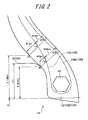
Fig. 2 is a sectional view of a bead portion of a pneumatic radial tire for heavy load according to one embodiment of the present invention. -
Fig. 3 is an analytic modeling view of an analytic example showing a distribution of shear strain in the bead portion, where the higher density of dots refer the larger shear strain. -
Fig. 4 is an analytic modeling view of an analytic example showing the shape of the bead portion under load. -
Fig. 5 is a sectional view of the bead portion showing an example of the shape of the carcass path line which is difficult to realize in terms of manufacturing a tire. -
Fig. 6 is a sectional view of the bead portion showing an example of the shape of the carcass path line which is difficult to realize in terms of manufacturing a tire. -
- 10
- pneumatic radial tire for heavy load
- 12
- steel radial carcass
- 12E
- turn-up portion
- 12M
- main carcass portion
- 20
- rim (standard rim)
- Hereinafter embodiments of the present invention are discussed. As shown in
Figs. 1 and2 , a pneumaticradial tire 10 for heavy load according to one embodiment of the present invention is provided with a steel radial carcass ply 12 (hereinafter referred to simply as carcass 12). Thecarcass 12 has amain carcass portion 12M toroidally extending betweenbead cores 16 ofbead portions 14, and a turn-upportion 12E turning up along thebead cores 16 from the inner side to the outer side in the radial direction of the tire. A belt constituting of multiple layers of belt layers is disposed on the outer circumferential side of the crown portion and atread 18 provided with grooves is formed on the belt in the outer side in the tire radial direction. It is noted that the profile ratio of the pneumaticradial tire 10 is 90% or more in this embodiment. - In this embodiment, as shown in
Fig. 2 , positions and distances are defined in the following manner.
R is a radius of astandard rim 20, Hf is a height of arim flange 22, P1 is a position on the tire outer surface with a radial distance of (R+1.18*Hf) from the central axis of the tire, and P2 is a position on the tire outer surface with a radial distance of (R+0.81*Hf) from the central axis of the tire. T1 and T2 are intersections of normal lines drawn from P1 and P2, respectively, to acarcass path line 13M of themain carcass portion 12M (hereinafter, referred to as main carcass path line) and acarcass path line 13E of the turn-upportion 12 E (hereinafter referred to as a turn-up carcass path line), and M1 and M2 are intersections of the normal lines and the maincarcass path line 13M. W1pt is a distance from P1 to T1, W1tm is a distance from T1 to M1, and W2pt is a distance from P2 to T2. - The present embodiment satisfies the following relationships (1) to (4).



and
- As the relationship (1) is satisfied, the durability of the carcass turn-up potion can be improve without rising of the temperature at the
bead portion 14 from that of the conventional tire. As the relationship (2) is satisfied, the durability of the carcass rubber layer is equal to or more than that of the conventional tire and the durability of the carcass turn-up portion can be improved. In addition, as the relationship (3) is satisfied, the cut resistance of carcass cords and the durability of the carcass turn-up portion can be improved. Further, as the relationship (4) is satisfied, the maincarcass path line 13M and the turn-up carcass path line 13E can take shapes available in terms of tire manufacturing even in a case that W2tm is small. - Accordingly, all of the durability of the carcass turn-up portion, the durability of the rubber layer of the
carcass 12 and the cut resistance of the carcass cords can be improved, so that a pneumaticradial tire 10 for heavy load with a longer lifetime can be provided. In other words, as compared with the conventional tire, all of the above-mentioned three kinds of durability can be improved simply by altering the carcass path line around thebead portion 14 without using an additional component. It is noted that the carcass path line around the bead core largely affects an improvement of the cut resistance of carcass cords (filaments) and the present embodiment utilizes this fact to realize an effective improvement of the cut resistance of carcass cords. - In order to confirm the effect of the present invention, the inventor carried out analytical calculation of strain caused in a tire under load with FEM (Finite Element Method) to evaluate strain resistance for one example of a pneumatic
radial tire 10 for heavy load of the above-mentioned embodiment (hereinafter referred to as ET), one example of a pneumatic radial tire for heavy load of the conventional tire (hereinafter referred to as CT) and four examples of pneumatic radial tire for heavy load for comparison (hereinafter referred to as RT 1-4). - In these analysis examples, all the tires are for a construction vehicle (OR tire) and have a size of 46/90R57.
- Conditions of each of the bead portion in this analysis example are shown in Table 1.
[Table 1] CT RT1 RT 2 RT 3 RT 4 ET Tire condition W1pt (ratio to SH) 5.0% 5.2% 6.2% 6.2% 6.8% 6.2% W1tm (ratio to SH) 3.3% 3.2% 2.3% 1.6% 3.2% 2.3% W2tm (ratio to SH) 4.2% 5.4% 2.5% 3.9% 3.9% 3.9% W1pt-W2pt (ratio to SH) 1.8% 2.6% 2.7% 1.1% 2.9% 2.4% Evaluation index for strain Shear strain of carcass turn-up portion 100 92 88 79 78 81 Shear strain of carcass rubber layer 100 100 95 110 95 99 Compressio n strain of carcass cord 100 150 70 80 85 82 Evaluation result from drum test Heat generation of bead portion - Close to CT Close to CT Close to CT CT + 6 degC Close to CT Troubles in bead portion Abort due to a separation at carcass turn-up portion Abort due to cut of a carcass cord Complete but small separation found in carcass turn-up portion Complete but a crack found in carcass rubber layer Complete but small separation found in carcass turn-up portion Complete with no trouble Traveling time (H) 400 450 500 500 500 500 - In this analysis example, strains were calculated with FEM in a condition that all tires were fitted on a standard rim (TRA) and the specified internal pressure (TRA) and the specified load (TRA) were applied. Suppose an evaluation index for the conventional tire is 100, evaluation indexes for the other tires, which were values relative to the index for the conventional tire, were calculated. The results are shown in Table 1 as well. Regarding the strain in Table 1, the smaller evaluation index represents the better performance.
- As can be seen from Table 1, the Embodiment Tire (ET) has better evaluation indexes in all of shear strain of the carcass turn-up portion, shear strain of the carcass rubber layer and compression strain of the carcass cord.
- In addition, it is confirmed in this analysis example that when the tire receives a load to induce collapse deformation, the amount of collapse toward the
rim flange 22 is the maximum and the shear strain is maximized at the T1 portion, as shown inFig. 3 . - Further, it is also confirmed in this analysis example that as compared to the
model 1 which is the Conventional tire, the model 2 which has small W1tm as with the present invention can reduce the collapse of the T1 portion under deflation (internal pressure: 50kPa) and thus can reduce the shear strain. Note that themodels 1 and 2 have the same W1pt. - In order to confirm the effect of the present invention, the inventor actually manufactured the above-mentioned Embodiment tire, Reference tires and Conventional tire, and conducted a durability test of a bead portion to evaluate the durability.
- In these examples, all the tires were fitted on the standard rim and then the temperature of the bead portion was measured under a condition that the specified internal pressure and 100% of the specified load (TRA) were applied, traveling speed was 8 km/h and the drum diameter was 5 meters. The measurement results are shown in Table 1 as well.
- Then, 170% of the specified load (TRA) was applied and the drum test was performed for 500 hours. Either of a case that the test could be performed for 500 hours and a case that the test could be performed only less than 500 hours, the bead portions were taken apart to evaluate troubles in the bead portions. The results are shown in Table 1 as well.
- As can be seen form Table 1, Example tire and Reference tires 1-4 had longer traveling time than Conventional tire. Further, Example tire and Reference tires 2-4 could travel for 500 hours.
- Example tire sufficiently satisfied all of the three kinds of durability, i.e., 1) durability of the turn-up portion of the carcass around the bead core, 2) durability of the rubber layer of the carcass and 3) cut resistance of the carcass cords (filaments).
- The embodiments of the present invention have been discussed by way of example, but these embodiments are merely examples and the present invention can be altered as far as it is not depart from the gist of the invention. In addition, the scope of the present invention is, of course, not limited to the above-discussed embodiments.
Claims (1)
- A pneumatic radial tire for heavy load comprising at least one steel radial carcass composed of a main carcass portion extending in a toroidal shape between a pair of bead cores and turn-up portions turning up along the bead cores from the inner side to the outer side in the radial direction of the tire, wherein the following relationships are satisfied on condition that the tire is fitted on a standard rim and inflated with an internal pressure of 50 kPa:


and
where SH is a tire section height, R is a rim radius, Hf is a height of a rim flange of a standard rim, P1 is a position on the tire outer surface with a radial distance of (R+1.18*Hf) from the central axis of the tire, P2 is a position on the tire outer surface with a radial distance of (R+0.81*Hf) from the central axis of the tire, T 1 and T2 are intersections of normal lines drawn from P1 and P2, respectively, to said main carcass portion and said turn-up portion, M1 and M2 are intersections of said normal lines and said main carcass portion, W1pt is a distance from P1 to T1, W1tm is a distance from T1 to M1, and W2pt is a distance from P2 to T2.
Applications Claiming Priority (2)
| Application Number | Priority Date | Filing Date | Title |
|---|---|---|---|
| JP2006331253A JP4724103B2 (en) | 2006-12-08 | 2006-12-08 | Heavy duty pneumatic radial tire |
| PCT/JP2007/071053 WO2008072425A1 (en) | 2006-12-08 | 2007-10-29 | Heavy duty pneumatic radial tire |
Publications (3)
| Publication Number | Publication Date |
|---|---|
| EP2090445A1 true EP2090445A1 (en) | 2009-08-19 |
| EP2090445A4 EP2090445A4 (en) | 2010-10-27 |
| EP2090445B1 EP2090445B1 (en) | 2012-02-01 |
Family
ID=39511454
Family Applications (1)
| Application Number | Title | Priority Date | Filing Date |
|---|---|---|---|
| EP07830787A Not-in-force EP2090445B1 (en) | 2006-12-08 | 2007-10-29 | Heavy duty pneumatic radial tire |
Country Status (8)
| Country | Link |
|---|---|
| US (1) | US8291952B2 (en) |
| EP (1) | EP2090445B1 (en) |
| JP (1) | JP4724103B2 (en) |
| CN (1) | CN101553372B (en) |
| AT (1) | ATE543667T1 (en) |
| BR (1) | BRPI0720145B1 (en) |
| ES (1) | ES2381046T3 (en) |
| WO (1) | WO2008072425A1 (en) |
Cited By (2)
| Publication number | Priority date | Publication date | Assignee | Title |
|---|---|---|---|---|
| EP2345548A4 (en) * | 2008-10-21 | 2012-05-02 | Bridgestone Corp | Tire |
| WO2012065939A1 (en) * | 2010-11-18 | 2012-05-24 | Societe De Technologie Michelin | Tire having dissymmetrical beads |
Families Citing this family (5)
| Publication number | Priority date | Publication date | Assignee | Title |
|---|---|---|---|---|
| JP5986502B2 (en) * | 2012-12-26 | 2016-09-06 | 住友ゴム工業株式会社 | Evaluation method of carcass durability at bead part of heavy duty tire |
| JP6318480B2 (en) * | 2013-06-21 | 2018-05-09 | 横浜ゴム株式会社 | Pneumatic tire |
| US10994578B2 (en) * | 2015-09-14 | 2021-05-04 | Jiangsu University | Method for improving production process for wide-base truck radial tire |
| FR3069191A1 (en) * | 2017-07-18 | 2019-01-25 | Compagnie Generale Des Etablissements Michelin | PNEUMATIC WITH BOURRELET'S ZONE IS ALLEGEE |
| USD1108962S1 (en) | 2023-08-01 | 2026-01-13 | Austin Markman | Multi-function container lid with integrated knife or straightedge cleaner |
Family Cites Families (12)
| Publication number | Priority date | Publication date | Assignee | Title |
|---|---|---|---|---|
| JP2713729B2 (en) * | 1988-05-13 | 1998-02-16 | 株式会社ブリヂストン | Pneumatic radial tire for heavy loads |
| JP2900259B2 (en) * | 1988-06-20 | 1999-06-02 | 横浜ゴム株式会社 | Pneumatic radial tire for heavy loads |
| JPH04185510A (en) | 1990-11-20 | 1992-07-02 | Bridgestone Corp | Pneumatic radial tire for construction vehicle |
| JP2644952B2 (en) * | 1992-08-25 | 1997-08-25 | 住友ゴム工業株式会社 | Pneumatic radial tire |
| GB9813965D0 (en) * | 1997-07-05 | 1998-08-26 | Hankook Tire Manufacturing Com | Radial tyre |
| JP4021540B2 (en) * | 1998-02-18 | 2007-12-12 | 株式会社ブリヂストン | Heavy duty pneumatic radial tires |
| FR2779387B1 (en) * | 1998-06-05 | 2000-08-11 | Michelin & Cie | REINFORCED RADIAL TIRE SADDLE |
| FR2810924B1 (en) * | 2000-07-03 | 2003-04-11 | Michelin Soc Tech | TIRE WITH IMPROVED STRUCTURE BUCKLES |
| JP4046502B2 (en) * | 2001-11-20 | 2008-02-13 | 株式会社ブリヂストン | Pneumatic radial tire |
| JP2005199762A (en) * | 2004-01-13 | 2005-07-28 | Bridgestone Corp | Pneumatic radial tire for heavy load |
| JP2006199111A (en) | 2005-01-19 | 2006-08-03 | Bridgestone Corp | Pneumatic tire, and method for using pneumatic tire |
| JP2006218936A (en) | 2005-02-09 | 2006-08-24 | Bridgestone Corp | Pneumatic radial tire for heavy load |
-
2006
- 2006-12-08 JP JP2006331253A patent/JP4724103B2/en active Active
-
2007
- 2007-10-29 BR BRPI0720145A patent/BRPI0720145B1/en not_active IP Right Cessation
- 2007-10-29 ES ES07830787T patent/ES2381046T3/en active Active
- 2007-10-29 US US12/516,984 patent/US8291952B2/en not_active Expired - Fee Related
- 2007-10-29 AT AT07830787T patent/ATE543667T1/en active
- 2007-10-29 EP EP07830787A patent/EP2090445B1/en not_active Not-in-force
- 2007-10-29 WO PCT/JP2007/071053 patent/WO2008072425A1/en not_active Ceased
- 2007-10-29 CN CN2007800453014A patent/CN101553372B/en not_active Expired - Fee Related
Non-Patent Citations (2)
| Title |
|---|
| No further relevant documents disclosed * |
| See also references of WO2008072425A1 * |
Cited By (5)
| Publication number | Priority date | Publication date | Assignee | Title |
|---|---|---|---|---|
| EP2345548A4 (en) * | 2008-10-21 | 2012-05-02 | Bridgestone Corp | Tire |
| WO2012065939A1 (en) * | 2010-11-18 | 2012-05-24 | Societe De Technologie Michelin | Tire having dissymmetrical beads |
| FR2967612A1 (en) * | 2010-11-18 | 2012-05-25 | Michelin Soc Tech | PNEUMATIC WITH DISSYMMETRIC BOURRELETS. |
| RU2541578C2 (en) * | 2010-11-18 | 2015-02-20 | Компани Женераль Дез Этаблиссман Мишлен | Pneumatic tire with asymmetrical lips |
| US9579933B2 (en) | 2010-11-18 | 2017-02-28 | Compagnie Generale Des Etablissements Michelin | Tire with dissymmetrical beads |
Also Published As
| Publication number | Publication date |
|---|---|
| CN101553372A (en) | 2009-10-07 |
| EP2090445B1 (en) | 2012-02-01 |
| JP2008143291A (en) | 2008-06-26 |
| US8291952B2 (en) | 2012-10-23 |
| BRPI0720145B1 (en) | 2019-08-13 |
| JP4724103B2 (en) | 2011-07-13 |
| EP2090445A4 (en) | 2010-10-27 |
| WO2008072425A1 (en) | 2008-06-19 |
| ES2381046T3 (en) | 2012-05-22 |
| US20100059161A1 (en) | 2010-03-11 |
| ATE543667T1 (en) | 2012-02-15 |
| BRPI0720145A2 (en) | 2014-02-04 |
| CN101553372B (en) | 2011-03-23 |
Similar Documents
| Publication | Publication Date | Title |
|---|---|---|
| EP1872972B1 (en) | Heavy duty pneumatic tire | |
| JP4008013B1 (en) | Pneumatic tire | |
| EP2017094B1 (en) | Pneumatic tire | |
| EP2090445B1 (en) | Heavy duty pneumatic radial tire | |
| EP2796300B1 (en) | Pneumatic tire for heavy loads | |
| EP2113398A1 (en) | Pneumatic radial tire | |
| US8245745B2 (en) | Pneumatic tire having land portion with buried reinforcing member | |
| US20040007305A1 (en) | Pneumatic tire | |
| US9987883B2 (en) | Pneumatic tire | |
| US8863800B2 (en) | Pneumatic tire with specified carcass folded section and notched portion | |
| EP2583837B1 (en) | Pneumatic radial tire for automobiles | |
| JP6442228B2 (en) | Pneumatic tires for passenger cars | |
| EP1908609B1 (en) | Pneumatic tire for heavy load | |
| EP2803505B1 (en) | Heavy duty pneumatic tire | |
| CN108248299A (en) | Pneumatic tire | |
| JP4017641B2 (en) | Flat pneumatic radial tire for heavy loads | |
| US9950570B2 (en) | Pneumatic tire | |
| EP3189979B1 (en) | Pneumatic tire | |
| EP3181375B1 (en) | Pneumatic tire | |
| JP4763187B2 (en) | Pneumatic tire | |
| JP2010116065A (en) | Pneumatic tire | |
| CN110914076B (en) | Tires with a reduced weight bead area | |
| JP2009248751A (en) | Pneumatic radial tire | |
| JP4763902B2 (en) | Pneumatic tire | |
| JP7742286B2 (en) | pneumatic tires |
Legal Events
| Date | Code | Title | Description |
|---|---|---|---|
| PUAI | Public reference made under article 153(3) epc to a published international application that has entered the european phase |
Free format text: ORIGINAL CODE: 0009012 |
|
| 17P | Request for examination filed |
Effective date: 20090604 |
|
| AK | Designated contracting states |
Kind code of ref document: A1 Designated state(s): AT BE BG CH CY CZ DE DK EE ES FI FR GB GR HU IE IS IT LI LT LU LV MC MT NL PL PT RO SE SI SK TR |
|
| DAX | Request for extension of the european patent (deleted) | ||
| A4 | Supplementary search report drawn up and despatched |
Effective date: 20100924 |
|
| RIC1 | Information provided on ipc code assigned before grant |
Ipc: B60C 9/08 20060101ALI20100920BHEP Ipc: B60C 3/04 20060101ALI20100920BHEP Ipc: B60C 15/06 20060101AFI20080703BHEP |
|
| RIC1 | Information provided on ipc code assigned before grant |
Ipc: B60C 9/08 20060101ALI20110505BHEP Ipc: B60C 15/06 20060101AFI20110505BHEP Ipc: B60C 3/04 20060101ALI20110505BHEP |
|
| GRAP | Despatch of communication of intention to grant a patent |
Free format text: ORIGINAL CODE: EPIDOSNIGR1 |
|
| GRAS | Grant fee paid |
Free format text: ORIGINAL CODE: EPIDOSNIGR3 |
|
| GRAA | (expected) grant |
Free format text: ORIGINAL CODE: 0009210 |
|
| RIN1 | Information on inventor provided before grant (corrected) |
Inventor name: ASARI, JYUNYAC/O BRIDGESTONE CORPORATION |
|
| AK | Designated contracting states |
Kind code of ref document: B1 Designated state(s): AT BE BG CH CY CZ DE DK EE ES FI FR GB GR HU IE IS IT LI LT LU LV MC MT NL PL PT RO SE SI SK TR |
|
| REG | Reference to a national code |
Ref country code: GB Ref legal event code: FG4D |
|
| REG | Reference to a national code |
Ref country code: CH Ref legal event code: EP Ref country code: AT Ref legal event code: REF Ref document number: 543667 Country of ref document: AT Kind code of ref document: T Effective date: 20120215 |
|
| REG | Reference to a national code |
Ref country code: DE Ref legal event code: R096 Ref document number: 602007020483 Country of ref document: DE Effective date: 20120329 |
|
| REG | Reference to a national code |
Ref country code: ES Ref legal event code: FG2A Ref document number: 2381046 Country of ref document: ES Kind code of ref document: T3 Effective date: 20120522 |
|
| REG | Reference to a national code |
Ref country code: NL Ref legal event code: VDEP Effective date: 20120201 |
|
| LTIE | Lt: invalidation of european patent or patent extension |
Effective date: 20120201 |
|
| PG25 | Lapsed in a contracting state [announced via postgrant information from national office to epo] |
Ref country code: LT Free format text: LAPSE BECAUSE OF FAILURE TO SUBMIT A TRANSLATION OF THE DESCRIPTION OR TO PAY THE FEE WITHIN THE PRESCRIBED TIME-LIMIT Effective date: 20120201 Ref country code: IS Free format text: LAPSE BECAUSE OF FAILURE TO SUBMIT A TRANSLATION OF THE DESCRIPTION OR TO PAY THE FEE WITHIN THE PRESCRIBED TIME-LIMIT Effective date: 20120601 Ref country code: NL Free format text: LAPSE BECAUSE OF FAILURE TO SUBMIT A TRANSLATION OF THE DESCRIPTION OR TO PAY THE FEE WITHIN THE PRESCRIBED TIME-LIMIT Effective date: 20120201 |
|
| PG25 | Lapsed in a contracting state [announced via postgrant information from national office to epo] |
Ref country code: PT Free format text: LAPSE BECAUSE OF FAILURE TO SUBMIT A TRANSLATION OF THE DESCRIPTION OR TO PAY THE FEE WITHIN THE PRESCRIBED TIME-LIMIT Effective date: 20120601 Ref country code: FI Free format text: LAPSE BECAUSE OF FAILURE TO SUBMIT A TRANSLATION OF THE DESCRIPTION OR TO PAY THE FEE WITHIN THE PRESCRIBED TIME-LIMIT Effective date: 20120201 Ref country code: BE Free format text: LAPSE BECAUSE OF FAILURE TO SUBMIT A TRANSLATION OF THE DESCRIPTION OR TO PAY THE FEE WITHIN THE PRESCRIBED TIME-LIMIT Effective date: 20120201 Ref country code: PL Free format text: LAPSE BECAUSE OF FAILURE TO SUBMIT A TRANSLATION OF THE DESCRIPTION OR TO PAY THE FEE WITHIN THE PRESCRIBED TIME-LIMIT Effective date: 20120201 Ref country code: LV Free format text: LAPSE BECAUSE OF FAILURE TO SUBMIT A TRANSLATION OF THE DESCRIPTION OR TO PAY THE FEE WITHIN THE PRESCRIBED TIME-LIMIT Effective date: 20120201 Ref country code: GR Free format text: LAPSE BECAUSE OF FAILURE TO SUBMIT A TRANSLATION OF THE DESCRIPTION OR TO PAY THE FEE WITHIN THE PRESCRIBED TIME-LIMIT Effective date: 20120502 |
|
| REG | Reference to a national code |
Ref country code: AT Ref legal event code: MK05 Ref document number: 543667 Country of ref document: AT Kind code of ref document: T Effective date: 20120201 |
|
| PG25 | Lapsed in a contracting state [announced via postgrant information from national office to epo] |
Ref country code: CY Free format text: LAPSE BECAUSE OF FAILURE TO SUBMIT A TRANSLATION OF THE DESCRIPTION OR TO PAY THE FEE WITHIN THE PRESCRIBED TIME-LIMIT Effective date: 20120201 |
|
| PG25 | Lapsed in a contracting state [announced via postgrant information from national office to epo] |
Ref country code: SE Free format text: LAPSE BECAUSE OF FAILURE TO SUBMIT A TRANSLATION OF THE DESCRIPTION OR TO PAY THE FEE WITHIN THE PRESCRIBED TIME-LIMIT Effective date: 20120201 Ref country code: CZ Free format text: LAPSE BECAUSE OF FAILURE TO SUBMIT A TRANSLATION OF THE DESCRIPTION OR TO PAY THE FEE WITHIN THE PRESCRIBED TIME-LIMIT Effective date: 20120201 Ref country code: RO Free format text: LAPSE BECAUSE OF FAILURE TO SUBMIT A TRANSLATION OF THE DESCRIPTION OR TO PAY THE FEE WITHIN THE PRESCRIBED TIME-LIMIT Effective date: 20120201 Ref country code: SI Free format text: LAPSE BECAUSE OF FAILURE TO SUBMIT A TRANSLATION OF THE DESCRIPTION OR TO PAY THE FEE WITHIN THE PRESCRIBED TIME-LIMIT Effective date: 20120201 Ref country code: DK Free format text: LAPSE BECAUSE OF FAILURE TO SUBMIT A TRANSLATION OF THE DESCRIPTION OR TO PAY THE FEE WITHIN THE PRESCRIBED TIME-LIMIT Effective date: 20120201 Ref country code: EE Free format text: LAPSE BECAUSE OF FAILURE TO SUBMIT A TRANSLATION OF THE DESCRIPTION OR TO PAY THE FEE WITHIN THE PRESCRIBED TIME-LIMIT Effective date: 20120201 |
|
| PG25 | Lapsed in a contracting state [announced via postgrant information from national office to epo] |
Ref country code: SK Free format text: LAPSE BECAUSE OF FAILURE TO SUBMIT A TRANSLATION OF THE DESCRIPTION OR TO PAY THE FEE WITHIN THE PRESCRIBED TIME-LIMIT Effective date: 20120201 Ref country code: IT Free format text: LAPSE BECAUSE OF FAILURE TO SUBMIT A TRANSLATION OF THE DESCRIPTION OR TO PAY THE FEE WITHIN THE PRESCRIBED TIME-LIMIT Effective date: 20120201 |
|
| PLBE | No opposition filed within time limit |
Free format text: ORIGINAL CODE: 0009261 |
|
| STAA | Information on the status of an ep patent application or granted ep patent |
Free format text: STATUS: NO OPPOSITION FILED WITHIN TIME LIMIT |
|
| 26N | No opposition filed |
Effective date: 20121105 |
|
| PG25 | Lapsed in a contracting state [announced via postgrant information from national office to epo] |
Ref country code: AT Free format text: LAPSE BECAUSE OF FAILURE TO SUBMIT A TRANSLATION OF THE DESCRIPTION OR TO PAY THE FEE WITHIN THE PRESCRIBED TIME-LIMIT Effective date: 20120201 |
|
| REG | Reference to a national code |
Ref country code: DE Ref legal event code: R097 Ref document number: 602007020483 Country of ref document: DE Effective date: 20121105 |
|
| PG25 | Lapsed in a contracting state [announced via postgrant information from national office to epo] |
Ref country code: MC Free format text: LAPSE BECAUSE OF NON-PAYMENT OF DUE FEES Effective date: 20121031 |
|
| REG | Reference to a national code |
Ref country code: CH Ref legal event code: PL |
|
| GBPC | Gb: european patent ceased through non-payment of renewal fee |
Effective date: 20121029 |
|
| PG25 | Lapsed in a contracting state [announced via postgrant information from national office to epo] |
Ref country code: LI Free format text: LAPSE BECAUSE OF NON-PAYMENT OF DUE FEES Effective date: 20121031 Ref country code: DE Free format text: LAPSE BECAUSE OF NON-PAYMENT OF DUE FEES Effective date: 20130501 Ref country code: CH Free format text: LAPSE BECAUSE OF NON-PAYMENT OF DUE FEES Effective date: 20121031 Ref country code: GB Free format text: LAPSE BECAUSE OF NON-PAYMENT OF DUE FEES Effective date: 20121029 Ref country code: BG Free format text: LAPSE BECAUSE OF FAILURE TO SUBMIT A TRANSLATION OF THE DESCRIPTION OR TO PAY THE FEE WITHIN THE PRESCRIBED TIME-LIMIT Effective date: 20120501 |
|
| REG | Reference to a national code |
Ref country code: IE Ref legal event code: MM4A |
|
| REG | Reference to a national code |
Ref country code: DE Ref legal event code: R119 Ref document number: 602007020483 Country of ref document: DE Effective date: 20130501 |
|
| PG25 | Lapsed in a contracting state [announced via postgrant information from national office to epo] |
Ref country code: IE Free format text: LAPSE BECAUSE OF NON-PAYMENT OF DUE FEES Effective date: 20121029 |
|
| PG25 | Lapsed in a contracting state [announced via postgrant information from national office to epo] |
Ref country code: MT Free format text: LAPSE BECAUSE OF FAILURE TO SUBMIT A TRANSLATION OF THE DESCRIPTION OR TO PAY THE FEE WITHIN THE PRESCRIBED TIME-LIMIT Effective date: 20120201 |
|
| PG25 | Lapsed in a contracting state [announced via postgrant information from national office to epo] |
Ref country code: TR Free format text: LAPSE BECAUSE OF FAILURE TO SUBMIT A TRANSLATION OF THE DESCRIPTION OR TO PAY THE FEE WITHIN THE PRESCRIBED TIME-LIMIT Effective date: 20120201 |
|
| PG25 | Lapsed in a contracting state [announced via postgrant information from national office to epo] |
Ref country code: LU Free format text: LAPSE BECAUSE OF NON-PAYMENT OF DUE FEES Effective date: 20121029 |
|
| PG25 | Lapsed in a contracting state [announced via postgrant information from national office to epo] |
Ref country code: HU Free format text: LAPSE BECAUSE OF FAILURE TO SUBMIT A TRANSLATION OF THE DESCRIPTION OR TO PAY THE FEE WITHIN THE PRESCRIBED TIME-LIMIT Effective date: 20071029 |
|
| REG | Reference to a national code |
Ref country code: FR Ref legal event code: CA Effective date: 20140812 |
|
| REG | Reference to a national code |
Ref country code: FR Ref legal event code: PLFP Year of fee payment: 9 |
|
| REG | Reference to a national code |
Ref country code: FR Ref legal event code: PLFP Year of fee payment: 10 |
|
| REG | Reference to a national code |
Ref country code: FR Ref legal event code: PLFP Year of fee payment: 11 |
|
| REG | Reference to a national code |
Ref country code: FR Ref legal event code: PLFP Year of fee payment: 12 |
|
| PGFP | Annual fee paid to national office [announced via postgrant information from national office to epo] |
Ref country code: ES Payment date: 20191122 Year of fee payment: 13 |
|
| PGFP | Annual fee paid to national office [announced via postgrant information from national office to epo] |
Ref country code: FR Payment date: 20201022 Year of fee payment: 14 |
|
| REG | Reference to a national code |
Ref country code: ES Ref legal event code: FD2A Effective date: 20220128 |
|
| PG25 | Lapsed in a contracting state [announced via postgrant information from national office to epo] |
Ref country code: ES Free format text: LAPSE BECAUSE OF NON-PAYMENT OF DUE FEES Effective date: 20201030 |
|
| PG25 | Lapsed in a contracting state [announced via postgrant information from national office to epo] |
Ref country code: FR Free format text: LAPSE BECAUSE OF NON-PAYMENT OF DUE FEES Effective date: 20211031 |