JP2009248751A - Pneumatic radial tire - Google Patents
Pneumatic radial tire Download PDFInfo
- Publication number
- JP2009248751A JP2009248751A JP2008099291A JP2008099291A JP2009248751A JP 2009248751 A JP2009248751 A JP 2009248751A JP 2008099291 A JP2008099291 A JP 2008099291A JP 2008099291 A JP2008099291 A JP 2008099291A JP 2009248751 A JP2009248751 A JP 2009248751A
- Authority
- JP
- Japan
- Prior art keywords
- cord
- belt
- strand
- tire
- strands
- Prior art date
- Legal status (The legal status is an assumption and is not a legal conclusion. Google has not performed a legal analysis and makes no representation as to the accuracy of the status listed.)
- Withdrawn
Links
Images


Classifications
-
- D—TEXTILES; PAPER
- D07—ROPES; CABLES OTHER THAN ELECTRIC
- D07B—ROPES OR CABLES IN GENERAL
- D07B1/00—Constructional features of ropes or cables
- D07B1/06—Ropes or cables built-up from metal wires, e.g. of section wires around a hemp core
- D07B1/0606—Reinforcing cords for rubber or plastic articles
- D07B1/0613—Reinforcing cords for rubber or plastic articles the reinforcing cords being characterised by the rope configuration
-
- D—TEXTILES; PAPER
- D07—ROPES; CABLES OTHER THAN ELECTRIC
- D07B—ROPES OR CABLES IN GENERAL
- D07B2201/00—Ropes or cables
- D07B2201/20—Rope or cable components
- D07B2201/2015—Strands
- D07B2201/2021—Strands characterised by their longitudinal shape
-
- D—TEXTILES; PAPER
- D07—ROPES; CABLES OTHER THAN ELECTRIC
- D07B—ROPES OR CABLES IN GENERAL
- D07B2401/00—Aspects related to the problem to be solved or advantage
- D07B2401/20—Aspects related to the problem to be solved or advantage related to ropes or cables
- D07B2401/2005—Elongation or elasticity
- D07B2401/201—Elongation or elasticity regarding structural elongation
-
- D—TEXTILES; PAPER
- D07—ROPES; CABLES OTHER THAN ELECTRIC
- D07B—ROPES OR CABLES IN GENERAL
- D07B2501/00—Application field
- D07B2501/20—Application field related to ropes or cables
- D07B2501/2046—Tire cords
Abstract
Description
本発明は、空気入りラジアルタイヤに関するものである。 The present invention relates to a pneumatic radial tire.
近年、トラック輸送の効率向上を目的としたトラックの開発が積極的に押し進められており、それに伴い耐久性能に優れた、偏平率が70%以下の重荷重用空気入りラジアルタイヤの開発が要望されている。 In recent years, the development of trucks for the purpose of improving the efficiency of truck transportation has been actively promoted, and accordingly, the development of heavy-duty pneumatic radial tires with excellent durability and flatness of 70% or less has been requested. Yes.
このスーパーシングルタイヤと呼ばれる扁平率の小さい空気入りラジアルタイヤでは、ベルト部の剛性不足によるタイヤ耐久性の低下やトレッド部の耐偏摩耗性を改善するため、ベルトに、ワーキングベルト(主ベルト)とともに、タイヤ周方向に対して実質的に0°の角度でスチールコードを配設した層(0°ベルト)を設けることが提案されている。かかるタイヤによれば、ワーキングベルトのみを配設したタイヤに比して、タイヤへの内圧充填時および、タイヤの負荷転動時における、トレッドの半径方向外方への膨出を効果的に抑制して、ベルトの耐久性を高めることができると考えられる。 In pneumatic radial tires with a small flatness ratio called super single tires, in order to reduce tire durability due to insufficient rigidity of the belt and to improve uneven wear resistance of the tread, together with the working belt (main belt) It has been proposed to provide a layer (0 ° belt) in which steel cords are arranged at an angle of substantially 0 ° with respect to the tire circumferential direction. According to such a tire, it is possible to effectively prevent the tread from bulging outward in the radial direction when the tire is filled with internal pressure and when the tire is rolling with a load, compared to a tire provided with only a working belt. Thus, it is considered that the durability of the belt can be improved.
しかしながら、通常のスチールコードのような剛直なコードをタイヤ周方向に実質的に0°の角度で配設した場合、タイヤ加硫時に拡張することが困難になる。そのため、これらのスチールコードとしてはコードのS−S曲線の傾きが、1〜2%までは緩やかで、それ以上は急激に大きくなる、いわゆるハイエロンゲーションコードが用いられ、これにより加硫時の拡張を容易にしている。 However, when a rigid cord such as a normal steel cord is disposed at a substantially 0 ° angle in the tire circumferential direction, it is difficult to expand at the time of tire vulcanization. Therefore, as these steel cords, so-called high elongation cords are used in which the slope of the SS curve of the cord is gentle up to 1 to 2% and suddenly increases beyond that. Easy expansion.
このようなハイエロンゲーションコードとしては、一般に複撚り構造のコードが用いられているが、従来の複撚り構造のコードでは、加硫時にゴムがコード内部に侵入することで多数のフィラメントがコード内部で拘束されてしまう。その結果、コードは、ゴム付き状態では低荷重域での伸びが十分に確保できず、タイヤ走行中のコードに過度の歪がかかり、応力集中により耐久性が低下するという問題がある(下記特許文献1参照)。 As such a high elongation cord, a cord with a double twist structure is generally used. However, in a conventional cord with a double twist structure, a large number of filaments are formed inside the cord by rubber entering the cord during vulcanization. It will be restrained by. As a result, there is a problem that the cord cannot be sufficiently stretched in the low load region when the rubber is attached, the cord during tire running is excessively strained, and the durability decreases due to stress concentration (the following patents) Reference 1).
なお、下記特許文献2には、3×4の複撚り構造のスチールコードにおいて、波状にくせ付けした素線を用いて撚り合わせることが開示されている。しかしながら、この文献は、該スチールコードを、タイヤ周方向に対して所定の角度で交差させて設けるワーキングベルトに使用することを開示するだけで0°ベルトへの適用については開示されていない。また、素線をくせ付けすることで、素線間に隙間を設けてコード内部にゴムを侵入させるものであり、本発明の特徴を何ら示唆するものではない。
本発明は、上記問題に鑑みてなされたものであり、加硫後のゴム付き状態でも低荷重域での伸びを確保することができ、これを0°ベルトのコードとして用いることで、タイヤ周方向のベルト剛性と拘束性を向上してタイヤの耐久性と耐偏摩耗性を向上することができる空気入りラジアルタイヤを提供することを目的とする。 The present invention has been made in view of the above problems, and can ensure elongation in a low load region even in a state with rubber after vulcanization, and by using this as a cord of a 0 ° belt, An object of the present invention is to provide a pneumatic radial tire capable of improving the belt rigidity and restraint property in the direction and improving the durability and uneven wear resistance of the tire.
本発明に係る空気入りラジアルタイヤは、左右一対のビードコアにて両端部が係止されたカーカスと、トレッド部における前記カーカスの外周側で、互いに交差し延在させたスチールコードからなる少なくとも2層の主ベルトと、タイヤ周方向に対して実質的に0°の角度でスチールコードを延在させた0°ベルトとを備えた空気入りラジアルタイヤにおいて、前記0°ベルトを構成するスチールコードは、4本の素線を撚り合わせてなるストランドを4本撚り合わせてなる4×4構造の複撚り構造のコードであって、前記ストランドを構成する前記各素線が長手方向に連続波を有するように波付けされ、該素線の連続波の波付け高さhとストランド径dとが0.90≦h/d≦1.00の関係を満たし、前記コードを構成する前記各ストランドが長手方向に連続波を有するように波付けされ、該ストランドの連続波の波付け高さHとコード径Dとが0.90≦H/D≦1.00の関係を満たし、コード撚りピッチPcとコード径Dとが5.5≦Pc/D≦6.5の関係を満たし、ストランド撚りピッチPsとコード径Dとが2.5≦Ps/D≦3.5の関係を満たすものである。 A pneumatic radial tire according to the present invention includes a carcass whose both ends are locked by a pair of left and right bead cores, and at least two layers of steel cords that intersect with each other and extend on the outer peripheral side of the carcass in a tread portion. In the pneumatic radial tire including the main belt and the 0 ° belt in which the steel cord is extended at an angle of substantially 0 ° with respect to the tire circumferential direction, the steel cord constituting the 0 ° belt is: A cord of a 4 × 4 double twisted structure in which four strands are formed by twisting four strands so that each strand constituting the strand has a continuous wave in the longitudinal direction. The strands of corrugated height h and strand diameter d satisfy the relationship of 0.90 ≦ h / d ≦ 1.00, and each strand constituting the cord And the cord undulation height H and cord diameter D of the strand satisfy the relationship of 0.90 ≦ H / D ≦ 1.00, and the cord twist pitch Pc and cord diameter D satisfy the relationship of 5.5 ≦ Pc / D ≦ 6.5, and strand twist pitch Ps and cord diameter D satisfy the relationship of 2.5 ≦ Ps / D ≦ 3.5. is there.
本発明によれば、コードを構成するストランドと該ストランドを構成する素線とにそれぞれ所定の型付けを施してなる4×4構造の複撚り構造のスチールコードとすることにより、コード内部へのゴムの侵入を防ぐことができ、そのため、加硫後のゴム付き状態でも低荷重域での伸びを確保することができる。よって、これを0°ベルトコードとして用いることにより、タイヤ加硫時の拡張挙動を容易にすることができ、また、タイヤ中でも低荷重域のコード伸びを保持して走行中の応力集中を分散することができる。しかも、このような低荷重域での伸びを確保しつつ、タイヤへの内圧充填時やタイヤの負荷転動時におけるタイヤ周方向のベルト剛性と拘束性を向上することができ、タイヤの耐久性を向上するとともに偏摩耗の発生を抑制することができる。 According to the present invention, a steel cord having a double twist structure having a 4 × 4 structure, in which a strand constituting the cord and the strands constituting the strand are respectively subjected to predetermined molding, can be used. Can be prevented, so that elongation in a low load region can be secured even in a state with rubber after vulcanization. Therefore, by using this as a 0 ° belt cord, the expansion behavior at the time of tire vulcanization can be facilitated, and even in the tire, the cord elongation in the low load region is maintained and the stress concentration during traveling is dispersed. be able to. In addition, while ensuring elongation in such a low load region, the belt rigidity and restraint in the tire circumferential direction can be improved when filling the tire with internal pressure or when rolling the tire, and the durability of the tire can be improved. And the occurrence of uneven wear can be suppressed.
以下、本発明に係る実施形態の空気入りラジアルタイヤを図面を参照し説明する。 Hereinafter, a pneumatic radial tire according to an embodiment of the present invention will be described with reference to the drawings.
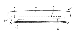
図1は、重荷重用の空気入りラジアルタイヤの1例を示すタイヤTの半断面図であり、符号1は4枚のベルト層からなるベルト、符号2はカーカス、符号3はトレッド部、符号4はビード部、符号5はサイドウォール部をそれぞれ示す。
FIG. 1 is a half sectional view of a tire T showing an example of a heavy-duty pneumatic radial tire. Reference numeral 1 denotes a belt composed of four belt layers,
タイヤTは、左右一対のビード部4間に、タイヤ幅方向に延在するスチールコードをタイヤ周方向に所定間隔で配列した1枚のカーカス2を有する。カーカス2は、その両端部がビード部3に埋設されたビードコア6の周りにビードフィラー7を挟み込むようにしてタイヤの内側から外側に折り返され係止されている。トレッド部3におけるカーカス2の外周側には、4枚のベルト層からなるベルト1が配設されている。
The tire T has a
図2は実施形態のタイヤTのトレッド部3の断面を模式的に示し、ベルト構成を説明するものである。図2において、ベルト1は、タイヤ半径方向内側から順に、第1ベルト11、第2ベルト12、第3ベルト13及び第4ベルト14との4層で構成されている(いずれもベルトは破線で示す)。
FIG. 2 schematically illustrates a cross-section of the
第1ベルト11と第3ベルト13は、タイヤの主ベルト(ワーキングベルト)をなすベルト層であり、従来一般的なベルト用スチールコードが所定間隔でタイヤ周方向に対して一定角度で配列され、互いにコード交差し配設されている。
The
第4ベルト14は、耐カット性とゴム侵入性に優れるスチールコードからなるタイヤ周方向に一定角度で配列された保護ベルト、いわゆるトップベルトであり、耐外傷耐久性や更新性を改善している。
The
第2ベルト12は、タイヤ周方向に対して実質的に0°の角度でスチールコードをタイヤ幅方向に所定間隔で配列して延在させた、本発明に係る0°ベルトである。
The
この0°ベルト12を構成するスチールコードCは、図3に示すように、4本の素線(フィラメント)Fを撚り合わせてなるストランドSを更に4本撚り合わせてなる4×4構造の複撚り構造のコードである。
As shown in FIG. 3, the steel cord C constituting the 0 °
このようにスチールコードCを「4×4」の複撚り構造とした理由は次の通りである。すなわち、ストランド本数を3本にして「3×4」構造にしたり、素線の本数を3本にして「4×3」構造にすると、素線径がもとのままではコード強力が低下するため、補強強度を維持するためにはコード本数を増やす必要があり、カレンダーによるゴム引き前のコードリール掛け工数が増し不利だからである。また、「3×4」や「4×3」構造で、「4×4」構造と同じコード強力を維持すると、素線径を太くする必要があってコードの曲げ剛性が大きくなり、タイヤの接地形状の変化が大きくなって、高速操縦安定性と乗り心地が低下するためである。また、「5×4」構造のようにストランドの本数を5本以上にしたり、「4×5」構造のように素線を5本以上にすると、コード打ち込み本数の密度は減少させることができるが、タイヤの肉厚が増してタイヤ重量が大きくなるためである。また、ストランド本数を5本以上にした場合や素線を5本以上にした場合でも、素線径を細くすることで「4×4」構造と同等の強力を維持できるが、その場合、素線の伸線工程が増して製造コストが増大してしまう。 The reason why the steel cord C has a “4 × 4” double twist structure as described above is as follows. That is, if the number of strands is set to 3 to form a “3 × 4” structure, or the number of strands is set to 3 and the structure is set to “4 × 3”, the cord strength is reduced with the wire diameter unchanged. Therefore, in order to maintain the reinforcing strength, it is necessary to increase the number of cords, which is disadvantageous because the man-hour for cord reel before rubber drawing by the calendar increases. If the same cord strength as that of the “4 × 4” structure is maintained in the “3 × 4” or “4 × 3” structure, it is necessary to increase the wire diameter and increase the bending rigidity of the cord. This is because the change in the ground contact shape becomes large, and the high-speed steering stability and the ride comfort are lowered. If the number of strands is 5 or more as in the “5 × 4” structure, or the number of strands is 5 or more as in the “4 × 5” structure, the density of the number of cords can be reduced. However, this is because the tire thickness increases and the tire weight increases. Even when the number of strands is 5 or more or when the number of strands is 5 or more, the same strength as the “4 × 4” structure can be maintained by reducing the strand diameter. The wire drawing process increases and the manufacturing cost increases.
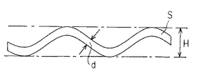
ストランドSを構成する各素線Fは、図4に示すように、その長手方向に連続波を有するように波付け(型付け)されている。この型付けは、螺旋状の連続波とすることもできるが、平面的な正弦波であることが好ましい。また、素線Fの波付け高さをhとし、ストランドSの外径(ストランド径)をdとして、0.90≦h/d≦1.00の関係を満たすように、4本の素線Fが撚り合わされている。これにより、図5に示すように、ストランドSは各素線Fが相互に密着して、ストランドSにおける4本の素線Fによって囲まれた内部空間Ksにゴムが侵入しないように形成することができる。上記h/dが1.00より大きいと、タイヤ加硫時にゴムが内部に侵入して、低荷重域の伸びが十分でなくなる。逆に、上記h/dが0.90よりも小さいと、コード裁断時の端末のバラケ長さが大きくなり、フレア性が悪化する。なお、図4中のdfは素線径を示す。 As shown in FIG. 4, each strand F constituting the strand S is corrugated (shaped) so as to have a continuous wave in its longitudinal direction. This typing can be a spiral continuous wave, but is preferably a planar sine wave. In addition, assuming that the corrugated height of the strand F is h and the outer diameter (strand diameter) of the strand S is d, the four strands are satisfied so as to satisfy the relationship of 0.90 ≦ h / d ≦ 1.00. F is twisted together. Thus, as shown in FIG. 5, the strand S is formed so that the strands F are in close contact with each other and the rubber does not enter the internal space Ks surrounded by the four strands F in the strand S. Can do. If h / d is greater than 1.00, rubber penetrates into the tire during vulcanization of the tire, and the elongation in the low load region becomes insufficient. Conversely, if h / d is smaller than 0.90, the terminal length at the time of code cutting becomes large, and the flare property deteriorates. In addition, df in FIG. 4 shows a strand diameter.
コードCを構成する各ストランドSは、図6に示すように、その長手方向に連続波を有するように波付け(型付け)されている。この型付けは、螺旋状の連続波とすることもできるが、平面的な正弦波であることが好ましい。また、ストランドSの波付け高さをHとし、コードCの外径(コード径)をDとして、0.90≦H/D≦1.00の関係を満たすように、4本のストランドSが撚り合わされている。これにより、図3に示すように、コードCは各ストランドSが相互に密着して、コードCにおける4本のストランドSによって囲まれた内部空間Kcにゴムが侵入しないように形成することができる。上記H/Dが1.00より大きいと、タイヤ加硫時にゴムが内部に侵入して、低荷重域の伸びが十分でなくなる。逆に、上記H/Dが0.90よりも小さいと、コード裁断時の端末のバラケ長さが大きくなり、フレア性が悪化する。 As shown in FIG. 6, each strand S constituting the cord C is corrugated (shaped) so as to have a continuous wave in its longitudinal direction. This typing can be a spiral continuous wave, but is preferably a planar sine wave. In addition, assuming that the corrugated height of the strand S is H and the outer diameter (cord diameter) of the cord C is D, the four strands S satisfy the relationship of 0.90 ≦ H / D ≦ 1.00. Twisted. Accordingly, as shown in FIG. 3, the cord C can be formed such that the strands S are in close contact with each other and the rubber does not enter the internal space Kc surrounded by the four strands S in the cord C. . If the above H / D is larger than 1.00, rubber penetrates into the inside during tire vulcanization, and the elongation in the low load region becomes insufficient. On the other hand, if the H / D is smaller than 0.90, the length of the terminal breakage at the time of code cutting becomes large, and the flare property deteriorates.
このスチールコードCは、コード撚りピッチPcとコード径Dとが5.5≦Pc/D≦6.5の関係を満たし、かつ、ストランド撚りピッチPsとコード径Dとが2.5≦Ps/D≦3.5の関係を満たすように構成されている。上記Pc/Dが6.5よりも大きいと、十分な低荷重域での伸びが得られず、逆に、Pc/Dが5.5よりも小さいと、伸びの向上には有効であるが、形状が不均一となる。上記Ps/Dが3.5よりも大きいと、十分な低荷重域での伸びが得られず、逆に、Ps/Dが2.5よりも小さいと、伸びの向上には有効であるが、形状が不均一となる。 In this steel cord C, the cord twist pitch Pc and the cord diameter D satisfy the relationship of 5.5 ≦ Pc / D ≦ 6.5, and the strand twist pitch Ps and the cord diameter D are 2.5 ≦ Ps / It is configured to satisfy the relationship of D ≦ 3.5. If the Pc / D is larger than 6.5, it is not possible to obtain an elongation in a sufficiently low load region. Conversely, if the Pc / D is smaller than 5.5, it is effective for improving the elongation. , The shape becomes non-uniform. When Ps / D is larger than 3.5, elongation in a sufficiently low load region cannot be obtained. Conversely, when Ps / D is smaller than 2.5, it is effective for improving elongation. , The shape becomes non-uniform.
このような撚り構造を持つスチールコードCは、素線Fを型付けしてから、その波付け高さhとストランドdが上記関係を満たすように4本の該素線Fを撚り合わせてストランドSを形成し、更に、該ストランドSを型付けしてから、その波付け高さHとコード径Dが上記関係を満たすように4本の該ストランドSを撚り合わせることにより製造することができる。その際、素線F及びストランドSに所定の型付けがなされていることにより、各素線F間及び各ストランドS間に隙間なくしっかりと撚り合わせることができ、内部へのゴムの侵入を防止することができる。なお、素線FやストランドSの型付けは、型付けピンやローラーを千鳥状に配した公知の型付け装置を用いて行うことができる。また、ストランドSを撚り合わせる方向は、素線Fを撚り合わせる方向と同方向であることが好ましい。また、素線FとストランドSの上記型付けは、タイヤからスチールコードCを取り出して各ストランドSや素線Fに分解した後でも、概ね元の状態が保持されていることから、製品タイヤからでも上記型付け構成を特定することは可能である。 In the steel cord C having such a twisted structure, the strand F is formed by twisting the four strands F so that the corrugated height h and the strand d satisfy the above relationship after the strand F is molded. And then twisting the four strands S so that the corrugation height H and the cord diameter D satisfy the above relationship. At that time, since the strands F and the strands S are given a predetermined type, the strands F and the strands S can be tightly twisted together without gaps, preventing rubber from entering the interior. be able to. The wire F and the strand S can be molded using a known molding apparatus in which molding pins and rollers are arranged in a staggered manner. The direction in which the strands S are twisted is preferably the same direction as the direction in which the strands F are twisted. In addition, the above-described molding of the strands F and strands S is substantially the same as the original state after the steel cord C is taken out of the tire and disassembled into the strands S and strands F. It is possible to specify the typed configuration.
このようにして得られたスチールコードCは、上記4×4の複撚り構造であるため、加硫後のゴムが付いた状態で、縦軸を荷重(N)、横軸を伸び(%)とするS−S曲線において、図7に示すように、低荷重域では緩やかな傾きで、荷重が大きくなると急激に傾きが大きくなる変曲点Zを有する半弾性コードとしての挙動を示す。具体的には、低荷重域での引張弾性率が5000N/mm2以下であることが好ましく、より好ましくは4000〜5000N/mm2である。 Since the steel cord C obtained in this way has the above-mentioned 4 × 4 double twist structure, the ordinate indicates the load (N) and the abscissa indicates the elongation (%) with the vulcanized rubber attached. As shown in FIG. 7, the SS curve shows a behavior as a semi-elastic cord having an inflection point Z that has a gentle slope in a low load region and a slope that suddenly increases as the load increases. Specifically, the tensile elastic modulus in a low load region is preferably 5000 N / mm 2 or less, more preferably 4000 to 5000 N / mm 2 .
本実施形態においては、前記低荷重域での傾きの接線Xと前記変曲点以降の傾きの接線Yとの交点の伸びA(%)(図7参照)が、0.5≦A<2.0であることが好適である。この交点の伸びAが0.5%未満であると、走行時の応力分散が不充分である傾向となり、2.0%以上であると、0°ベルトの十分な拘束力が得られない傾向にある。 In the present embodiment, the elongation A (%) (see FIG. 7) of the intersection between the tangent line X of the slope in the low load region and the tangent line Y of the slope after the inflection point is 0.5 ≦ A <2. 0.0 is preferred. If the elongation A at this intersection is less than 0.5%, the stress distribution during running tends to be insufficient, and if it is 2.0% or more, a sufficient restraint force of the 0 ° belt cannot be obtained. It is in.
特に、本実施形態であると、タイヤの加硫成形時に、スチールコードCの内部にゴムが侵入していないため、コード内部で素線がゴムによって拘束されることがなく、そのため、ゴム付き状態でも、低荷重域の傾きを緩やかなものとし、十分な低荷重域での伸びを確保することができる。従って、上記交点Aの伸び(%)は、1.0≦A<2.0であることがより好ましい。 In particular, in the present embodiment, the rubber does not enter the steel cord C at the time of vulcanization molding of the tire, so that the strands are not restrained by the rubber inside the cord. However, it is possible to make the inclination in the low load region gentle and ensure the elongation in the sufficiently low load region. Accordingly, the elongation (%) at the intersection A is more preferably 1.0 ≦ A <2.0.
0°ベルト12のベルト1内での位置関係は特に制限されることはないが、0°ベルトのタイヤ半径方向外側に少なくとも一層の前記主ベルトが配されていることが好ましい。より詳細には、0°ベルト12は、主ベルト11,13の層間、もしくは主ベルト11のタイヤ径方向内側でカーカス2との間に配置することが好ましい。0°ベルト12の幅は、タイヤ半径方向外側のベルト層13の幅の90%以下であることが好ましく、これにより、0°ベルトエッジ部分への応力集中を和らげることができ、該応力集中による歪みを受けることに起因するエッジ部分の耐久性低下を防ぐことができる。
The positional relationship of the 0 °
なお、0°ベルト12は、主ベルト13とトップベルト14との間に配設してもよいが、一般に、トップベルト14は主ベルト11,13に対し幅がその90%以下しかないため、この部分に0°ベルト12をその外側のベルト層に対して90%以下の幅で配設すると、0°ベルト12の幅が狭くなりすぎてショルダー部において十分な拘束力を得にくくなる。そのため、0°ベルト12は上記のように主ベルト11,13の間または主ベルト11とカーカス2の間に配設することが好ましい。また、この0°ベルト12のコードCは、上記のように内部にゴムが充填されていないため、一般的には錆やすいという問題があるが、主ベルト11,13の間や主ベルト11とカーカス2の間に配置されることで、トレッド表面から傷つきにくく、錆の問題を回避することができる。
The 0 °
一方、このように0°ベルトを主ベルトの間または主ベルトとカーカスの間に配設する場合に、0°ベルト層12が主ベルト層11,13よりも厚くなると、ベルト内部の歪が0°ベルト12に集中し、耐セパレーションが悪化するおそれがある。そのため、0°ベルト12のスチールコードCのコード径Dは、主ベルト11,13を構成するスチールコードのコード径よりも小径であることが好ましく、これにより、ベルトエッジ部でのセパレーションの進行を遅らせて、タイヤ耐久性を向上することができる。
On the other hand, when the 0 ° belt is disposed between the main belt or between the main belt and the carcass as described above, if the 0 °
上記0°ベルト12は、スチールコードCをタイヤTの周方向に連続でスパイラル状に巻回して設けることができる。スチールコードCのコード角度はタイヤ周方向に対して実質的に0°であり、例えば1本のコードCをタイヤTの幅方向にずらせながらスパイラル状に巻き付け成形される。また、数本のコードCを引き揃えてゴムで被覆したリボン状の帯状部材を、タイヤ成形の際に成形ドラム1周毎にリボン状の側端部同士を突き合わせながらスパイラル状に巻き付けることにより行われる。このようにスチールコードCをスパイラル状に連続に巻くことにより、ジョイント等の影響を受けず、十分なベルト剛性が得られる。
The 0 °
以上よりなる本実施形態の空気入りラジアルタイヤであると、上記構成の0°ベルトを具備することにより、タイヤの耐久性と耐偏摩耗性を向上することができ、特にトラック用の重荷重車両に使用される扁平率(タイヤの高さ/タイヤの総幅の比率)が60%以下のタイヤに好適である。 With the pneumatic radial tire of the present embodiment configured as described above, the durability and uneven wear resistance of the tire can be improved by providing the 0 ° belt having the above-described configuration, and particularly heavy-duty vehicles for trucks. It is suitable for a tire having a flatness ratio (ratio of tire height / total tire width) of 60% or less.
以下、本発明を実施例によって更に具体的に説明するが、本発明はこれら実施例に限定されるものではない。 EXAMPLES Hereinafter, although an Example demonstrates this invention further more concretely, this invention is not limited to these Examples.
図2に示すベルト構成を有するタイヤサイズ315/60R22.5のラジアルタイヤを試作した。0°ベルトは第2ベルト12に配置し、表1、2に記載の各スチールコードを使用した。第1〜4ベルトの構成は、実施例及び比較例を表3、従来例を表4に示す。なお、ベルト以外の各部位には全て共通の部材を使用した。また、表中の角度の欄で右、左はベルトコードの傾斜方向を表す。
A radial tire having a tire size of 315 / 60R22.5 having the belt configuration shown in FIG. 2 was prototyped. The 0 ° belt was placed on the
従来例は、図8に示す0°ベルト未使用の例である。この従来例のタイヤT1は、角度付きの第1〜第3ベルト(主ベルト)111,112,113と第4ベルト(トップベルト)114との4枚のベルト層よりなるベルト100を具備する空気入りラジアルタイヤである。
The conventional example is an example in which the 0 ° belt shown in FIG. 8 is not used. The tire T1 according to the conventional example includes an air having a
上記各タイヤについて、下記の評価を行った。結果を表1、2に示す。 The following evaluation was performed on each of the tires. The results are shown in Tables 1 and 2.
[引張試験]
各スチールコードを加硫ゴム付きの状態で引張試験(JIS G3510に準拠)を行い、図7に示すS−S曲線から低荷重域での傾きの接線Xと前記変曲点以降の傾きの接線Yとの交点の伸びA(%)を求めた。低荷重域での引張弾性率は、S−S曲線の原点付近における最大勾配部の接線から求められる100%伸びたと仮定したときの強度として算出した。
[Tensile test]
Each steel cord is subjected to a tensile test with vulcanized rubber (based on JIS G3510). From the SS curve shown in FIG. 7, the tangent line X of the slope in the low load region and the tangent line of the slope after the inflection point are shown. The elongation A (%) at the intersection with Y was determined. The tensile elastic modulus in the low load region was calculated as the strength when it was assumed that the elongation was 100% obtained from the tangent line of the maximum gradient portion near the origin of the SS curve.
[ゴム侵入性]
スチールコードをゴム中に埋め込んで加硫した後、ゴム中からコードを取り出し、コードを2分割して、上記内部空間Kcに面するストランドSの表面を目視観察し、ゴムが被覆されている面積を百分率で示した。また、ストランドSを2分割して、上記内部空間Ksに面する素線Fの表面を目視観察し、ゴム被覆されている面積を百分率で表した。そして、「前者のKcでの百分率/後者のKsでの百分率」として表示した。
[Rubber penetration]
The steel cord is embedded in rubber and vulcanized, then the cord is taken out from the rubber, the cord is divided into two, the surface of the strand S facing the internal space Kc is visually observed, and the area covered with rubber Was expressed as a percentage. Moreover, the strand S was divided into two, the surface of the strand F facing the internal space Ks was visually observed, and the area covered with rubber was expressed as a percentage. And it was displayed as “percentage of the former Kc / percentage of the latter Ks”.
[コード形状安定性]
コードの形状安定性は、撚り合わせたコードの外観を目視で観察した。○:良好、△:やや型崩れあるが使用に問題なし、×:型崩れあり、と評価した。
[Cord shape stability]
Regarding the shape stability of the cord, the appearance of the twisted cord was visually observed. ○: good, Δ: slightly out of shape but no problem in use, x: out of shape.
[フレア性]
300mm以上のコードを用いて、その一部を固定し固定箇所から50mm以上離れた箇所をコードの軸と直角にカッターを当てて切断し、端末のバラケ長さを測定した。比較例2をコントロールとして、バラケ長さを比較し、×:劣る(バラケ長さが長い)、○:良好(バラケ長さが同等以上)、と評価した。
[Flare]
Using a cord of 300 mm or more, a part of the cord was fixed, and a portion away from the fixed location by 50 mm or more was cut by applying a cutter perpendicular to the cord axis, and the length of the terminal was measured. Using Comparative Example 2 as a control, the lengths of the roses were compared and evaluated as x: inferior (the length of the rose was long), ○: good (the length of the rose was equal or greater).
[タイヤ耐久性]
表面が平滑な直径1700mmの鋼製回転ドラムを有するドラム試験機により、周辺温度38±3℃、タイヤ内圧900kPa、荷重3550kgで一定として、速度56km/hから12時間毎に8km/hずつ増加させ、故障が発生するまで走行させた。故障発生までの走行距離を、従来例を100とする指数で表1に示した。指数が大きいほど耐久性に優れる。
[Tire durability]
Increased by 8 km / h every 12 hours from a speed of 56 km / h using a drum testing machine with a steel rotating drum with a smooth surface and a diameter of 1700 mm. The car was run until a failure occurred. The distance traveled until the failure occurred is shown in Table 1 as an index with the conventional example being 100. The larger the index, the better the durability.
[耐偏摩耗性]
大型トラックの駆動輪に装着し、実車にて5万km走行後のトレッド接地面を観察し、偏摩耗の発生状態を従来例を基準として、良〜同等〜悪で判定した。

Attached to the driving wheel of a large truck, the tread contact surface after traveling 50,000 km with an actual vehicle was observed, and the occurrence of uneven wear was judged as good to equivalent to bad based on the conventional example.
表に示す通り、実施例1〜3では、コード内部へのゴムの侵入がなく、加硫後のゴム付き状態において十分な低荷重伸び特性が確保されていた。そのため、タイヤの耐久性及び耐偏摩耗性に優れていた。 As shown in the table, in Examples 1 to 3, there was no penetration of rubber into the cord, and sufficient low load elongation characteristics were ensured in a state with rubber after vulcanization. Therefore, the durability and uneven wear resistance of the tire were excellent.
これに対して、比較例1は、h/dが0.90未満であるため、フレア性が非常に悪く、コードをゴム被覆したトッピング反を裁断したときのコードのバラケが大きく、タイヤ成形に適さないものであった。また、比較例2は、h/dが1.00を超えているため、加硫後のゴム付き状態にて、コード内(詳細には、ストランドの内部空間Ks)にゴムが侵入し、そのため、低荷重域での伸びが不十分であり、走行時の歪みによる応力集中を分散できずタイヤの耐久性が低下していた。 On the other hand, in Comparative Example 1, since h / d is less than 0.90, the flare is very poor, and the cord has a large variation when cutting the topping with the cord covered with rubber. It was not suitable. In Comparative Example 2, since h / d exceeds 1.00, rubber penetrates into the cord (specifically, the internal space Ks of the strand) in a state with rubber after vulcanization. In addition, the elongation in the low load region is insufficient, the stress concentration due to strain during running cannot be dispersed, and the durability of the tire is reduced.
比較例3は、H/Dが0.90未満であるため、フレア性が非常に悪く、コードをゴム被覆したトッピング反を裁断したときのコードのバラケが大きく、タイヤ成形に適さないものであった。また、比較例4は、H/Dが1.00を超えているため、加硫後のゴム付き状態にて、コード内(詳細には、コードの内部空間Kc)にゴムが侵入し、そのため、低荷重域での伸びが不十分であり、走行時の歪みによる応力集中を分散できずタイヤの耐久性が低下していた。 In Comparative Example 3, since the H / D is less than 0.90, the flare is very poor, the cord has a large variation when the topping with the rubber covered is cut, and is not suitable for tire molding. It was. In Comparative Example 4, since H / D exceeds 1.00, rubber penetrates into the cord (specifically, the inner space Kc of the cord) with rubber after vulcanization. In addition, the elongation in the low load region is insufficient, the stress concentration due to strain during running cannot be dispersed, and the durability of the tire is reduced.
比較例5は、Pc/Dが5.5未満のため、伸びの向上には有効であるが、コード形状が安定せず、その結果、コード耐久性が低下し、タイヤの耐久性が低下していた。また、比較例6は、Pc/Dが6.5を超えるため、加硫後のゴム付き状態での低荷重域の伸びAが小さく、走行時の歪みによる応力集中を分散できずタイヤの耐久性が低下していた。 Comparative Example 5 is effective in improving elongation because Pc / D is less than 5.5. However, the cord shape is not stable, resulting in a decrease in cord durability and a decrease in tire durability. It was. Further, in Comparative Example 6, since Pc / D exceeds 6.5, the elongation A in the low load region in the state with rubber after vulcanization is small, and the stress concentration due to strain during running cannot be dispersed, and the durability of the tire The sex was decreasing.
比較例7は、Ps/Dが2.5未満のため、撚り歪みが大きくなり、コード耐久性が低下し、また、コード形状も安定せず、タイヤの耐久性が低下していた。また、比較例8は、Ps/Dが3.5を超えるため、加硫後のゴム付き状態での低荷重域の伸びAが小さく、走行時の歪みによる応力集中を分散できずタイヤの耐久性が低下していた。 In Comparative Example 7, since Ps / D was less than 2.5, the twist strain was increased, the cord durability was lowered, the cord shape was not stable, and the tire durability was lowered. Further, in Comparative Example 8, since Ps / D exceeds 3.5, the elongation A in the low load region with the rubber after vulcanization is small, and the stress concentration due to strain during running cannot be dispersed, resulting in durability of the tire. The sex was decreasing.
以上説明したように、本発明による空気入りラジアルタイヤは、ベルトの耐久性、耐偏摩耗性に優れることから重荷重用のトラックやバス用のタイヤに使用することができ、特に扁平率が60%以下のラジアルタイヤに好適である。 As described above, the pneumatic radial tire according to the present invention is excellent in belt durability and uneven wear resistance, and therefore can be used for heavy duty truck and bus tires. Particularly, the flatness is 60%. It is suitable for the following radial tires.
1…ベルト
2…カーカス
6…ビードコア
11,13…主ベルト
12…0°ベルト
C…スチールコード
S…ストランド
F…素線
DESCRIPTION OF SYMBOLS 1 ...
Claims (5)
前記0°ベルトを構成するスチールコードは、4本の素線を撚り合わせてなるストランドを4本撚り合わせてなる4×4構造の複撚り構造のコードであって、前記ストランドを構成する前記各素線が長手方向に連続波を有するように波付けされ、該素線の連続波の波付け高さhとストランド径dとが0.90≦h/d≦1.00の関係を満たし、前記コードを構成する前記各ストランドが長手方向に連続波を有するように波付けされ、該ストランドの連続波の波付け高さHとコード径Dとが0.90≦H/D≦1.00の関係を満たし、コード撚りピッチPcとコード径Dとが5.5≦Pc/D≦6.5の関係を満たし、ストランド撚りピッチPsとコード径Dとが2.5≦Ps/D≦3.5の関係を満たす、
ことを特徴とする空気入りラジアルタイヤ。 A carcass whose both ends are locked by a pair of left and right bead cores, at least two main belts made of steel cords that cross each other and extend on the outer periphery side of the carcass in the tread portion, and the tire circumferential direction A pneumatic radial tire having a 0 ° belt with a steel cord extending substantially at an angle of 0 °,
The steel cord constituting the 0 ° belt is a cord of a 4 × 4 double twist structure in which four strands obtained by twisting four strands are twisted, and each of the strands constituting the strand The strand is corrugated so as to have a continuous wave in the longitudinal direction, and the continuous wave corrugation height h of the strand and the strand diameter d satisfy a relationship of 0.90 ≦ h / d ≦ 1.00, Each strand constituting the cord is corrugated so as to have a continuous wave in the longitudinal direction, and the corrugation height H and cord diameter D of the continuous wave of the strand are 0.90 ≦ H / D ≦ 1.00. The cord twist pitch Pc and the cord diameter D satisfy the relationship of 5.5 ≦ Pc / D ≦ 6.5, and the strand twist pitch Ps and the cord diameter D satisfy 2.5 ≦ Ps / D ≦ 3. .5 satisfying the relationship,
A pneumatic radial tire characterized by that.
ことを特徴とする請求項1記載の空気入りラジアルタイヤ。 In the steel cord of the 0 ° belt, rubber does not enter the internal space surrounded by the four strands in each strand, and the internal space surrounded by the four strands in the cord Rubber has not penetrated into the
The pneumatic radial tire according to claim 1.
ことを特徴とする請求項1又は2に記載の空気入りラジアルタイヤ。 The steel cord of the 0 ° belt has a gentle slope in the low load region in the SS curve with the load (N) on the vertical axis and the elongation (%) on the horizontal axis with rubber after vulcanization. And an inflection point where the inclination increases when the load increases, and the elongation A (%) of the intersection of the tangent of the inclination in the low load region and the tangent of the inclination after the inflection point is 0.5 ≦ A <2.0.
The pneumatic radial tire according to claim 1 or 2, characterized in that
ことを特徴とする請求項1〜3のいずれか1項に記載の空気入りラジアルタイヤ。 The main belt of at least one layer is arranged outside the 0 ° belt in the tire radial direction, the width of the 0 ° belt is 90% or less of the width of the main belt outside the tire radial direction, and The cord diameter of the steel cord is smaller than the cord diameter of the steel cord constituting the main belt on the outer side in the tire radial direction,
The pneumatic radial tire according to any one of claims 1 to 3, wherein:
ことを特徴とする請求項1〜4のいずれか1項に記載の空気入りラジアルタイヤ。 The 0 ° belt is formed by continuously winding the steel cord having the 4 × 4 structure in the circumferential direction of the tire in a spiral shape.
The pneumatic radial tire according to any one of claims 1 to 4, wherein:
Priority Applications (1)
| Application Number | Priority Date | Filing Date | Title |
|---|---|---|---|
| JP2008099291A JP2009248751A (en) | 2008-04-07 | 2008-04-07 | Pneumatic radial tire |
Applications Claiming Priority (1)
| Application Number | Priority Date | Filing Date | Title |
|---|---|---|---|
| JP2008099291A JP2009248751A (en) | 2008-04-07 | 2008-04-07 | Pneumatic radial tire |
Publications (1)
| Publication Number | Publication Date |
|---|---|
| JP2009248751A true JP2009248751A (en) | 2009-10-29 |
Family
ID=41309851
Family Applications (1)
| Application Number | Title | Priority Date | Filing Date |
|---|---|---|---|
| JP2008099291A Withdrawn JP2009248751A (en) | 2008-04-07 | 2008-04-07 | Pneumatic radial tire |
Country Status (1)
| Country | Link |
|---|---|
| JP (1) | JP2009248751A (en) |
Cited By (5)
| Publication number | Priority date | Publication date | Assignee | Title |
|---|---|---|---|---|
| JP2014055369A (en) * | 2012-09-12 | 2014-03-27 | Yokohama Rubber Co Ltd:The | Steel cord and pneumatic radial tire for construction vehicle using the same |
| WO2015014639A2 (en) * | 2013-08-01 | 2015-02-05 | Nv Bekaert Sa | A steel cord and pneumatic tire |
| CN104343026A (en) * | 2013-08-01 | 2015-02-11 | 贝卡尔特公司 | Metal cord thread and rubber tire |
| WO2019086929A1 (en) * | 2017-10-31 | 2019-05-09 | Compagnie Generale Des Etablissements Michelin | Cable for a tire |
| EA039720B1 (en) * | 2013-08-01 | 2022-03-03 | Нв Бекаэрт Са | High elongation steel cord and pneumatic tire comprising said cord |
-
2008
- 2008-04-07 JP JP2008099291A patent/JP2009248751A/en not_active Withdrawn
Cited By (9)
| Publication number | Priority date | Publication date | Assignee | Title |
|---|---|---|---|---|
| JP2014055369A (en) * | 2012-09-12 | 2014-03-27 | Yokohama Rubber Co Ltd:The | Steel cord and pneumatic radial tire for construction vehicle using the same |
| WO2015014639A2 (en) * | 2013-08-01 | 2015-02-05 | Nv Bekaert Sa | A steel cord and pneumatic tire |
| CN104343026A (en) * | 2013-08-01 | 2015-02-11 | 贝卡尔特公司 | Metal cord thread and rubber tire |
| WO2015014639A3 (en) * | 2013-08-01 | 2015-04-02 | Nv Bekaert Sa | High elongation steel cord and pneumatic tire comprising said cord |
| JP2016529410A (en) * | 2013-08-01 | 2016-09-23 | エヌ ヴイ べカルト エス エイ | High elongation steel cord and pneumatic tire provided with this cord |
| EA039720B1 (en) * | 2013-08-01 | 2022-03-03 | Нв Бекаэрт Са | High elongation steel cord and pneumatic tire comprising said cord |
| WO2019086929A1 (en) * | 2017-10-31 | 2019-05-09 | Compagnie Generale Des Etablissements Michelin | Cable for a tire |
| CN111465734A (en) * | 2017-10-31 | 2020-07-28 | 米其林集团总公司 | Tire cable |
| US11655586B2 (en) | 2017-10-31 | 2023-05-23 | Compagnie Generale Des Etablissements Michelin | Cable for a tire |
Similar Documents
| Publication | Publication Date | Title |
|---|---|---|
| JP4663638B2 (en) | Heavy vehicle tires | |
| JP5635588B2 (en) | Heavy-duty vehicle tire having a layer of circumferential reinforcing elements | |
| JP4464700B2 (en) | Pneumatic tire and manufacturing method thereof | |
| JP5587739B2 (en) | Pneumatic tire | |
| AU2015250907B2 (en) | Tyre for vehicle of construction plant type | |
| US20120097306A1 (en) | Tire for Heavy Vehicles Comprising Layers of Peripheral Reinforcement Elements | |
| JP2013043548A (en) | Pneumatic radial tire for passenger car | |
| JP5580559B2 (en) | Steel cord for reinforcing rubber articles and tire using the same | |
| WO2012172778A1 (en) | Pneumatic radial tire | |
| JP4703644B2 (en) | Heavy duty pneumatic tire | |
| JP5294396B2 (en) | Pneumatic radial tire | |
| WO2013176082A1 (en) | Pneumatic radial tire for vehicle | |
| US9132700B2 (en) | Pneumatic tire | |
| JP2009248751A (en) | Pneumatic radial tire | |
| JP4888145B2 (en) | Pneumatic radial tire | |
| JP2009292425A (en) | Large-sized pneumatic radial tire | |
| JP2011162023A (en) | Pneumatic tire | |
| JP4553074B1 (en) | Pneumatic tire for passenger car and method for manufacturing pneumatic tire for passenger car | |
| WO2016024391A1 (en) | Pneumatic tire | |
| CN113613873B (en) | Pneumatic tire | |
| JP5495412B2 (en) | Steel cords and tires for rubber article reinforcement | |
| JP4903035B2 (en) | Radial tire | |
| JP2010018942A (en) | Steel cord for large-sized pneumatic radial tire | |
| JP4865274B2 (en) | Pneumatic radial tire | |
| JP2008088613A (en) | Steel cord, rubber-steel cord composite and heavy load pneumatic radial tire |
Legal Events
| Date | Code | Title | Description |
|---|---|---|---|
| A300 | Withdrawal of application because of no request for examination |
Free format text: JAPANESE INTERMEDIATE CODE: A300 Effective date: 20110607 |