EP2088610B1 - Containment and segregation compartment for switches and switch untis - Google Patents
Containment and segregation compartment for switches and switch untis Download PDFInfo
- Publication number
- EP2088610B1 EP2088610B1 EP08425071A EP08425071A EP2088610B1 EP 2088610 B1 EP2088610 B1 EP 2088610B1 EP 08425071 A EP08425071 A EP 08425071A EP 08425071 A EP08425071 A EP 08425071A EP 2088610 B1 EP2088610 B1 EP 2088610B1
- Authority
- EP
- European Patent Office
- Prior art keywords
- compartment
- switch
- cover
- terminal board
- frame
- Prior art date
- Legal status (The legal status is an assumption and is not a legal conclusion. Google has not performed a legal analysis and makes no representation as to the accuracy of the status listed.)
- Not-in-force
Links
Images


Classifications
-
- H—ELECTRICITY
- H01—ELECTRIC ELEMENTS
- H01H—ELECTRIC SWITCHES; RELAYS; SELECTORS; EMERGENCY PROTECTIVE DEVICES
- H01H71/00—Details of the protective switches or relays covered by groups H01H73/00 - H01H83/00
- H01H71/02—Housings; Casings; Bases; Mountings
- H01H71/0264—Mountings or coverplates for complete assembled circuit breakers, e.g. snap mounting in panel
-
- H—ELECTRICITY
- H01—ELECTRIC ELEMENTS
- H01H—ELECTRIC SWITCHES; RELAYS; SELECTORS; EMERGENCY PROTECTIVE DEVICES
- H01H9/00—Details of switching devices, not covered by groups H01H1/00 - H01H7/00
- H01H9/02—Bases, casings, or covers
- H01H9/0264—Protective covers for terminals
Definitions
- the present invention regards a containment compartment for a switch, especially a boxed switch, and a switch unit.
- the base is attached mechanically to the electrical panel and is connected electrically inside the electrical panel to an electric system which the switch is to be connected to.
- the base includes electrical connection terminals to enable the connection of the switch to an electric circuit, such as a line circuit or load circuit.
- the electrical panel is a structure built-in to the wall closed off by a panel which when opened permits access to the switch.
- the aim of this invention is to overcome the drawbacks mentioned with reference to the technical note.
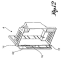
- the reference numeral 4 globally denotes a containment and segregation compartment for switches.
- the compartment 4 is suitable for inserting in a recess 6 of an electrical panel 8 fitted with a base 12 and an opening/closing hatch 16.
- the opening/closing hatch 16 can be removable from the panel 8 or attached to the panel 8 for example by a hinge, so that it can be opened.
- the recess 6 of the panel 8 is included between the base 12 and the hatch 16, and is able to accommodate at least one electric switch 20 through an aperture 7 on the front of the hatch 16.
- the switch 20 is attached to the electrical panel 8 by means of an insertion terminal board 24.
- the insertion terminal board 24 can be attached to the base 12 of the electrical panel 8 by interposing an attachment panel, for example, parallel to the base 12, or by interposing a small support frame comprising uprights and/ or crossbeams and relative threaded means of connection.
- the compartment 4 is advantageously situated between the switch 20 and a relative insertion terminal board 24.
- the insertion terminal board 24 comprises electric connection terminals 28 to a line circuit and/or load circuit able to receive complementary electric terminals of the associable switch 20.
- the compartment 4 comprises a frame 32 which defines a site of containment 36 able to accommodate at least partially the insertion terminal board 24 and the switch 20.
- the frame 32 is overall a box-like structure comprising a first and a second upright 40,44 as well upper crossbeam 48 and a lower crossbeam 52.
- the uprights 40,44 and the crossbeams 48,52 form a closed loop which define the site of containment.
- the frame 32 is open at a rear portion 56, able to interface with the insertion terminal board 24, and a front portion 60 able to receive the associable switch 20.
- the frame 32 is shaped so as to fit exactly against the insertion terminal board 24 so as to prevent access to the live parts adjacent to the terminal board 24.
- the frame 32 is shaped so as to fit exactly against the insertion terminal board 24 so that after having fitted the compartment 4 on to the terminal board 24, the latter is covered around its perimeter by the compartment 4.
- the frame 32 comprises a closure cover 64 able to close off the front portion 60, so as to close off access to the site of containment 36.
- the closure cover 64 can be moved independently of the hatch 16 of the electrical panel 8, so as to allow access to the site of containment 36 without having to open or remove the hatch 16 of the electrical panel 8.
- the closure cover 64 is mechanically separate from the hatch 16 of the electrical panel 8.
- the cover 64 in a closed configuration, sits flush with the front portion 60 of the compartment 4.
- the frame 32 of the compartment 4 comprises a housing recess 68 able to house at least partially the cover 64 of the compartment 4, in an open configuration of the cover 64.
- the housing recess is preferably situated in a position adjacent to an upright 40,44 of the frame 32, and preferably at the height of the upright at which the cover 64 is hinged.
- the closure cover 64 is therefore hinged to an upright 40,44 of the frame 32 so as to move in a rotatory movement in relation to said upright 40.
- Said closure cover 64 can for example rotate by 90 degrees and sit, in an open configuration, essentially perpendicular to the front portion 60 of the frame 32 or it can for example rotate 180 degrees to sit parallel to the front portion 60 ( figure 11 ).
- the closure cover 64 is attached to an upright 40,44 of the frame 32 by means of a rotor-translatory coupling, so as to be able to rotate in relation to an axis of the hinge X-X essentially parallel to the relative upright 40,44 and be able to translate in a perpendicular direction to the same axis of the hinge X-X, inserting itself at least partially inside the housing recess 68 ( figure 12 ).
- the housing recess 68 comprises insertion guides 72 of the cover 64 able to guide the cover inside the housing recess 68.
- the cover 64 of the compartment 4 presents an aperture 76 able to receive a protruding front portion 80 of the switch 20 fitted with a control lever 84, so as to be able to activate the control lever 84 of the switch 20 even when the cover 64 of the compartment 4 is closed.
- the cover 64 of the compartment 4 is fitted with a flap 88 able to close said aperture 76 of the cover 64 of the compartment 4, so as to prevent access inside the panel 8 following removal of the switch 20.
- the flap 88 is sliding and is situated adjacent to the aperture 76 of the closure cover 64 of the compartment 4.
- the flap 88 slides along an upper edge 92 which defines the aperture 76, according to a shutter movement.
- the flap 88 comprises a handle 96 to facilitate moving of the flap 88.
- the flap 88 comprises means of blocking, able to block the flap 88 in the open and/or closed position; according to a possible form of embodiment the flap 88 is fitted with a spring which keeps it automatically in the closed position when the switch 20 is not on.
- the compartment makes it possible to prevent accidental contact between an operator and the live parts of the terminal board, given that the compartment is shaped to fit exactly against the terminal board and is made in electrically insulated material.
- the operator can easily work on the switch inside the electrical panel, without interfering with the closure hatch of the panel which can be conveniently put away in the relative housing recess.
- closure hatch of the electrical panel can remain closed and the closure cover of the compartment, after being opened, can be conveniently inserted out of sight into the compartment housing recess. This way the operator has more space for manoeuvring.
Abstract
Description
- The present invention regards a containment compartment for a switch, especially a boxed switch, and a switch unit.
- To mechanically attach a boxed switch inside the inner compartment of an electrical panel and to ensure the electrical connection of such switch to an electric system the use of a support and electrical connection base is known of.
- The base is attached mechanically to the electrical panel and is connected electrically inside the electrical panel to an electric system which the switch is to be connected to.
- The base includes electrical connection terminals to enable the connection of the switch to an electric circuit, such as a line circuit or load circuit.
- The electrical panel is a structure built-in to the wall closed off by a panel which when opened permits access to the switch.
- Frequently the need arises to remove the switch from the electrical panel, for example so as to replace it, or to remove the switch temporarily from the panel and distance it from the same for maintenance operations on the electric system or tests on functioning with the system sectioned from auxiliary functions of the switch.
- Known state-of-the-art electrical panels present numerous drawbacks.
- In fact, in order to access the switches and remove and/or extract them from the electrical panel the door needs to be opened and the switch handled manually so as to extract or remove it.
- There is also a risk that the operator might accidentally come into contact with live parts, such as for example the parts of the terminal board itself or the bars of current remaining visible after removal of the switch.
- To obviate these drawbacks the creation of complex systems of segregation inside the electrical panel which prevent access to the live parts inside the electrical panel once the door of the electrical panel has been opened are known of.
- Such devices make the electrical panels complex and expensive.
- Electrical panels with switches which can be extracted with the door shut are also known of but such solutions are equally complex and complicated to produce.
- The document
US-A-5 172 300 discloses a compartment according to the preamble of claim 1. - The aim of this invention is to overcome the drawbacks mentioned with reference to the technical note.
- Such drawbacks and limitations are resolved by a containment and segregation compartment for the switch in accordance with claim 1.
- Other forms of embodiment of the invention are described in the subsequent claims.
- Further characteristics and advantages of the present invention will be evident from the description given below of its preferred embodiments made by way of an indicative and non-limiting example according to the following figures, wherein:
-
figure 1 shows a perspective view of the separate parts of a switch unit in accordance with a form of embodiment of the present invention; -
figure 2 shows a perspective view of the separate parts of the switch unit offigure 1 , in a partially assembled configuration; -
figure 3 shows a perspective view of the switch unit offigure 1 , in an assembly configuration with compartment hatch open; -
figure 4 shows a perspective view of the switch unit offigure 1 , in an assembly configuration with compartment hatch closed; -
figure 5 shows a perspective view of the switch unit offigure 1 , in an assembly configuration in an electricaql panel, with the door of the panel closed and the hatch of the compartment open; -
figure 6 shows a perspective view of the switch unit offigure 1 , in an assembly configuration in an electrical panel, with the door of the panel closed and the hatch of the compartment closed; -
Figure 7 shows a lateral view of the switch unit offigure 1 , from the side of the arrow VII infigure 1 ;figure 8 shows a lateral view of the switch unit offigure 2 , from the side of the arrow VIII infigure2 ;figure 9 shows a lateral view of the switch unit offigure 4 , from the side of the arrow IX infigure 4 ;figures 10-12 show perspective views of the compartment of the switch unit offigure 1 , in a closed configuration and in two open configurations respectively. - The elements or parts of elements common to the forms of embodiment described below will be indicated with the same reference numerals.
- With reference to the aforesaid figures, the
reference numeral 4 globally denotes a containment and segregation compartment for switches. - The
compartment 4 is suitable for inserting in arecess 6 of anelectrical panel 8 fitted with abase 12 and an opening/closing hatch 16. The opening/closing hatch 16 can be removable from thepanel 8 or attached to thepanel 8 for example by a hinge, so that it can be opened. Therecess 6 of thepanel 8 is included between thebase 12 and thehatch 16, and is able to accommodate at least oneelectric switch 20 through anaperture 7 on the front of thehatch 16. - The
switch 20 is attached to theelectrical panel 8 by means of aninsertion terminal board 24. Theinsertion terminal board 24 can be attached to thebase 12 of theelectrical panel 8 by interposing an attachment panel, for example, parallel to thebase 12, or by interposing a small support frame comprising uprights and/ or crossbeams and relative threaded means of connection. - The
compartment 4 is advantageously situated between theswitch 20 and a relativeinsertion terminal board 24. - The
insertion terminal board 24 compriseselectric connection terminals 28 to a line circuit and/or load circuit able to receive complementary electric terminals of theassociable switch 20. - According to one form of embodiment, the
compartment 4 comprises aframe 32 which defines a site ofcontainment 36 able to accommodate at least partially theinsertion terminal board 24 and theswitch 20. - For example, the
frame 32 is overall a box-like structure comprising a first and a second upright 40,44 as wellupper crossbeam 48 and alower crossbeam 52. - The
uprights crossbeams - The
frame 32 is open at arear portion 56, able to interface with theinsertion terminal board 24, and afront portion 60 able to receive theassociable switch 20. - Advantageously, the
frame 32 is shaped so as to fit exactly against theinsertion terminal board 24 so as to prevent access to the live parts adjacent to theterminal board 24. - In other words, the
frame 32 is shaped so as to fit exactly against theinsertion terminal board 24 so that after having fitted thecompartment 4 on to theterminal board 24, the latter is covered around its perimeter by thecompartment 4. - According to one form of embodiment, the
frame 32 comprises aclosure cover 64 able to close off thefront portion 60, so as to close off access to the site ofcontainment 36. According to one form of embodiment, theclosure cover 64 can be moved independently of thehatch 16 of theelectrical panel 8, so as to allow access to the site ofcontainment 36 without having to open or remove thehatch 16 of theelectrical panel 8. According to one possible form of embodiment, theclosure cover 64 is mechanically separate from thehatch 16 of theelectrical panel 8. - Preferably, the
cover 64, in a closed configuration, sits flush with thefront portion 60 of thecompartment 4. - According to one form of embodiment, the
frame 32 of thecompartment 4 comprises a housing recess 68 able to house at least partially thecover 64 of thecompartment 4, in an open configuration of thecover 64. - Specifically, the housing recess is preferably situated in a position adjacent to an upright 40,44 of the
frame 32, and preferably at the height of the upright at which thecover 64 is hinged. - The
closure cover 64 is therefore hinged to an upright 40,44 of theframe 32 so as to move in a rotatory movement in relation to said upright 40. Saidclosure cover 64 can for example rotate by 90 degrees and sit, in an open configuration, essentially perpendicular to thefront portion 60 of theframe 32 or it can for example rotate 180 degrees to sit parallel to the front portion 60 (figure 11 ). - According to one form of embodiment, the
closure cover 64 is attached to an upright 40,44 of theframe 32 by means of a rotor-translatory coupling, so as to be able to rotate in relation to an axis of the hinge X-X essentially parallel to the relative upright 40,44 and be able to translate in a perpendicular direction to the same axis of the hinge X-X, inserting itself at least partially inside the housing recess 68 (figure 12 ). - Preferably, the
housing recess 68 comprisesinsertion guides 72 of thecover 64 able to guide the cover inside thehousing recess 68. - According to one form of embodiment, the
cover 64 of thecompartment 4 presents anaperture 76 able to receive aprotruding front portion 80 of theswitch 20 fitted with acontrol lever 84, so as to be able to activate thecontrol lever 84 of theswitch 20 even when thecover 64 of thecompartment 4 is closed. - According to one form of embodiment, the
cover 64 of thecompartment 4 is fitted with aflap 88 able to close saidaperture 76 of thecover 64 of thecompartment 4, so as to prevent access inside thepanel 8 following removal of theswitch 20. - For example, the
flap 88 is sliding and is situated adjacent to theaperture 76 of theclosure cover 64 of thecompartment 4. - According to one form of embodiment, the
flap 88 slides along anupper edge 92 which defines theaperture 76, according to a shutter movement. - Preferably, the
flap 88 comprises ahandle 96 to facilitate moving of theflap 88. - Preferably, the
flap 88 comprises means of blocking, able to block theflap 88 in the open and/or closed position; according to a possible form of embodiment theflap 88 is fitted with a spring which keeps it automatically in the closed position when theswitch 20 is not on. - As may be seen from the description the containment and segregation department according to the invention allows the drawbacks described in the technical note to be overcome.
- In fact, the compartment makes it possible to prevent accidental contact between an operator and the live parts of the terminal board, given that the compartment is shaped to fit exactly against the terminal board and is made in electrically insulated material.
- Advantageously it is possible to perform operations of removal and/or extraction of the switch without having to open the hatch of the electric panel. In fact, it is possible to access the switch through the aperture of the closure cover of the compartment of the switch itself without affecting the compartments of the other switches on the electric panel.
- Advantageously, following removal of the switch, for example so as to conduct maintenance and /or replacement operations, it is possible to block access to the electrical panel through the flap, ensuring operator safety. In addition, the infiltration of liquid or dust inside the electrical panel following removal of the switch is thus prevented.
- Advantageously, the operator can easily work on the switch inside the electrical panel, without interfering with the closure hatch of the panel which can be conveniently put away in the relative housing recess.
- In fact the closure hatch of the electrical panel can remain closed and the closure cover of the compartment, after being opened, can be conveniently inserted out of sight into the compartment housing recess. This way the operator has more space for manoeuvring.
- A technician skilled in this area, may make numerous modifications and adjustments to the compartments described above so as to satisfy contingent and specific requirements, all moreover contained within the sphere of the invention as defined by the following claims.
Claims (13)
- Compartment of containment and segregation for switches (4), suitable for inserting in an electrical panel (8) and for being positioned between an electric switch (20) and a relative insertion terminal board (24) inside the electrical panel (8), the switch (20) and the insertion terminal board (24) comprise electrical connection terminals (28) to a line and/or load circuit, the compartment (4) comprising- a frame (32) which defines a site of containment (36) able to house at least partially the insertion terminal board (24) and the switch (20);- wherein the frame (32) is shaped to fit exactly against the insertion terminal board (24) so as to prevent access to the live electrical parts adjacent to the insertion terminal board (24),- and wherein the frame (32) comprises a closure cover (64) able to close off access to the site of containment (36), said cover (64) being moveable independently of the opening/closing hatch (16) of the electrical panel (8), so as to allow access to the site of containment (36) without having to open or remove the hatch (16) of the electrical panel (8),
wherein the cover of the compartment (64) presents an aperture (76) able to receive a protruding frontal portion (80) of the switch (20) fitted with a control lever (84), so as to be able to activate the control lever (84) of the switch (20) even when the cover (64) of the compartment (4) is closed,
characterised in that
the cover (64) of the compartment (4) is fitted with a flap (88) able to close said aperture (76) of the cover (64) of the compartment (4) so as to prevent access to the electrical panel (8) following removal of the switch (20). - Compartment (4) according to claim 1, wherein the closure cover, in a closed configuration, sits flush with a front portion (60) of the compartment (4), so as to prevent access to the site of containment (36) of the switch (20).
- Compartment (4) according to claim 1 or 2, wherein the closure cover (64) is shaped so as to fit against a frontal hole (7) of the hatch(16) of the electrical panel able to allow the insertion and extraction of the switch (20).
- Compartment (4) according to any one of the previous claims, wherein the frame (32) of the compartment (4) comprises a housing recess (68) able to accommodate at least partially the closure cover (64) of the compartment (4), in an open configuration of the cover (64).
- Compartment (4) according to claim 4, wherein said housing recess (68) is situated adjacent to an upright (40,44) of the frame (32).
- Compartment (4) according to claim 5, wherein the closure cover (64) is hinged to said upright (40,44) of the frame (32) so as to be able, in an open configuration, to slide inside said housing recess (68).
- Compartment (4) according to any one of the claims 4 to 6, wherein the closure cover (64) is connected to an upright (40,44) of the frame (4) by means of a rotor-translatory coupling, so as to be able to insert itself inside the housing recess (68) in an open configuration.
- Compartment (4) according to any one of the previous claims from 4 to 7, wherein the housing recess (68) comprises insertion guides (72) of the cover (64).
- Compartment (4) according to claim 1, wherein said flap (88) is sliding and is located adjacent to the aperture (76) of the closure cover (64) of the compartment (4).
- Compartment (4) according to claim 1 or 9, wherein said flap (88) slides along an upper edge (92) which defines the aperture (76), so as to close the aperture (76) according to a shutter movement.
- Compartment (4) according to claims 1, 9 or 10, wherein said flap (88) comprises a handle (96) to facilitate moving of the flap (88).
- Compartment (4) according to any one of the previous claims 1, 9, 10, 11, wherein said flap (88) comprises means of blocking, able to block the flap (88) in the open and/or closed position.
- Switch unit comprising a compartment (4) according to any one of the previous claims from 1 to 12, an insertion terminal board (24) and a switch (20) electrically connected to the insertion terminal board (24), the compartment (4) being situated between the insertion terminal board (24) and the switch (20).
Priority Applications (6)
| Application Number | Priority Date | Filing Date | Title |
|---|---|---|---|
| EP08425071A EP2088610B1 (en) | 2008-02-07 | 2008-02-07 | Containment and segregation compartment for switches and switch untis |
| AT08425071T ATE553493T1 (en) | 2008-02-07 | 2008-02-07 | CHAMBER FOR ACCOMMODATION AND SEPARATION OF SWITCHES AND SWITCHING UNITS |
| CL2009000251A CL2009000251A1 (en) | 2008-02-07 | 2009-02-05 | Containment tray for switches that can be inserted into an electrical panel, comprising a frame, with a door provided with a door to close an opening that receives a protruding portion of the switch, in order to prevent access to the panel after removing the switch. switch |
| CN200910005313.5A CN101505037B (en) | 2008-02-07 | 2009-02-05 | Containment and segregation compartment for switches and switch units |
| RU2009104147/07A RU2488908C2 (en) | 2008-02-07 | 2009-02-06 | Compartment for protection and insulation of switch and switches unit |
| CO09011553A CO6190095A1 (en) | 2008-02-07 | 2009-02-06 | CONTAINMENT AND SEGREGATION TRAY FOR INTERRUPTURES AND SWITCH GROUP |
Applications Claiming Priority (1)
| Application Number | Priority Date | Filing Date | Title |
|---|---|---|---|
| EP08425071A EP2088610B1 (en) | 2008-02-07 | 2008-02-07 | Containment and segregation compartment for switches and switch untis |
Publications (2)
| Publication Number | Publication Date |
|---|---|
| EP2088610A1 EP2088610A1 (en) | 2009-08-12 |
| EP2088610B1 true EP2088610B1 (en) | 2012-04-11 |
Family
ID=39637623
Family Applications (1)
| Application Number | Title | Priority Date | Filing Date |
|---|---|---|---|
| EP08425071A Not-in-force EP2088610B1 (en) | 2008-02-07 | 2008-02-07 | Containment and segregation compartment for switches and switch untis |
Country Status (6)
| Country | Link |
|---|---|
| EP (1) | EP2088610B1 (en) |
| CN (1) | CN101505037B (en) |
| AT (1) | ATE553493T1 (en) |
| CL (1) | CL2009000251A1 (en) |
| CO (1) | CO6190095A1 (en) |
| RU (1) | RU2488908C2 (en) |
Families Citing this family (2)
| Publication number | Priority date | Publication date | Assignee | Title |
|---|---|---|---|---|
| CN102412083A (en) * | 2010-09-20 | 2012-04-11 | 西门子公司 | Side plate apparatus used for isolating switch plug-in unit and plug-in unit thereof |
| WO2019041234A1 (en) * | 2017-08-31 | 2019-03-07 | 深圳昂泰智能有限公司 | Electric shock prevention and protection device, power distribution functional module, and power distribution apparatus |
Family Cites Families (7)
| Publication number | Priority date | Publication date | Assignee | Title |
|---|---|---|---|---|
| US4142225A (en) * | 1977-10-17 | 1979-02-27 | Square D Company | Panelboard assembly employing heat transmitting insulator assembly and a circuit breaker securing bead received in a circuit breaker housing recess |
| US4752233A (en) * | 1987-07-20 | 1988-06-21 | General Electric Company | Electric power panelboard adapter module |
| US5172300A (en) * | 1989-08-02 | 1992-12-15 | General Electric Company | Electric power distribution panelboard-switchboard assembly |
| US5894404A (en) * | 1997-05-28 | 1999-04-13 | General Electric Company | Circuit breaker panelboard enclosure |
| JPH11185587A (en) * | 1997-12-22 | 1999-07-09 | Matsushita Electric Works Ltd | Breaker circuit |
| RU2269851C9 (en) * | 2004-08-12 | 2006-06-10 | Общество с ограниченной ответственностью "Производственно коммерческая фирма "Автоматика" | Front panel of electrical device |
| RU43409U1 (en) * | 2004-09-07 | 2005-01-10 | Общество с ограниченной ответственностью "Производственно-коммерческая фирма "Автоматика" | CABINET OF COMPLETE DISTRIBUTION DEVICE |
-
2008
- 2008-02-07 EP EP08425071A patent/EP2088610B1/en not_active Not-in-force
- 2008-02-07 AT AT08425071T patent/ATE553493T1/en active
-
2009
- 2009-02-05 CL CL2009000251A patent/CL2009000251A1/en unknown
- 2009-02-05 CN CN200910005313.5A patent/CN101505037B/en not_active Expired - Fee Related
- 2009-02-06 RU RU2009104147/07A patent/RU2488908C2/en not_active IP Right Cessation
- 2009-02-06 CO CO09011553A patent/CO6190095A1/en active IP Right Grant
Also Published As
| Publication number | Publication date |
|---|---|
| RU2009104147A (en) | 2010-08-20 |
| EP2088610A1 (en) | 2009-08-12 |
| CN101505037A (en) | 2009-08-12 |
| CN101505037B (en) | 2014-03-19 |
| ATE553493T1 (en) | 2012-04-15 |
| RU2488908C2 (en) | 2013-07-27 |
| CL2009000251A1 (en) | 2010-02-05 |
| CO6190095A1 (en) | 2010-08-19 |
Similar Documents
| Publication | Publication Date | Title |
|---|---|---|
| EP2667467B1 (en) | Shutter door assembly for an electrical panel | |
| EP2228878B1 (en) | Circuit breaker with apparatus for preventing withdrawing or inserting of carriage of circuit breaker | |
| US4926286A (en) | Enclosed switchboard | |
| US20180090913A1 (en) | Medium voltage switchgear enclosure | |
| AU2002252966B2 (en) | Low voltage switchgear comprising a locking device for an appliance module | |
| US3920939A (en) | Circuit breaker protective shutter apparatus | |
| CN104350653A (en) | Shutter device for electrical switchgear panel, and related switchgear panel | |
| EP2088610B1 (en) | Containment and segregation compartment for switches and switch untis | |
| CN103177909B (en) | Termination | |
| US5901868A (en) | Switchgear and enclosure therefor | |
| KR101786716B1 (en) | Pad lock apparatus | |
| US5327321A (en) | Protective shutter assembly for electrical terminals and method of using same | |
| KR101128868B1 (en) | Switch | |
| EP3453041B1 (en) | Combination of a panel for accommodating a draw-out device and the draw-out device | |
| US4912747A (en) | Interlock device for electrical equipment | |
| JP4870649B2 (en) | switchboard | |
| EP2571121B1 (en) | Withdrawable unit with rotating electrical contacts | |
| EP3220497B1 (en) | Motor control center unit | |
| EP2482399B1 (en) | Interlocks for withdrawable circuit breakers | |
| AU2018236718A1 (en) | Heating device with a holding device for recording a control unit | |
| KR20090003144U (en) | Slide Type Cabinet Panel | |
| AU2018236709A1 (en) | Heating device with a holding device for recording a control unit | |
| CN211151121U (en) | Switch cabinet with observation window | |
| CN210898254U (en) | Interlocking structure of switching on and switching off and rocking handle | |
| EP3576235B1 (en) | Function unit interlock mechanism |
Legal Events
| Date | Code | Title | Description |
|---|---|---|---|
| PUAI | Public reference made under article 153(3) epc to a published international application that has entered the european phase |
Free format text: ORIGINAL CODE: 0009012 |
|
| AK | Designated contracting states |
Kind code of ref document: A1 Designated state(s): AT BE BG CH CY CZ DE DK EE ES FI FR GB GR HR HU IE IS IT LI LT LU LV MC MT NL NO PL PT RO SE SI SK TR |
|
| AX | Request for extension of the european patent |
Extension state: AL BA MK RS |
|
| 17P | Request for examination filed |
Effective date: 20100112 |
|
| AKX | Designation fees paid |
Designated state(s): AT BE BG CH CY CZ DE DK EE ES FI FR GB GR HR HU IE IS IT LI LT LU LV MC MT NL NO PL PT RO SE SI SK TR |
|
| GRAP | Despatch of communication of intention to grant a patent |
Free format text: ORIGINAL CODE: EPIDOSNIGR1 |
|
| GRAS | Grant fee paid |
Free format text: ORIGINAL CODE: EPIDOSNIGR3 |
|
| GRAA | (expected) grant |
Free format text: ORIGINAL CODE: 0009210 |
|
| AK | Designated contracting states |
Kind code of ref document: B1 Designated state(s): AT BE BG CH CY CZ DE DK EE ES FI FR GB GR HR HU IE IS IT LI LT LU LV MC MT NL NO PL PT RO SE SI SK TR |
|
| REG | Reference to a national code |
Ref country code: GB Ref legal event code: FG4D |
|
| REG | Reference to a national code |
Ref country code: CH Ref legal event code: EP |
|
| REG | Reference to a national code |
Ref country code: AT Ref legal event code: REF Ref document number: 553493 Country of ref document: AT Kind code of ref document: T Effective date: 20120415 |
|
| REG | Reference to a national code |
Ref country code: IE Ref legal event code: FG4D |
|
| REG | Reference to a national code |
Ref country code: DE Ref legal event code: R096 Ref document number: 602008014780 Country of ref document: DE Effective date: 20120606 |
|
| REG | Reference to a national code |
Ref country code: NL Ref legal event code: VDEP Effective date: 20120411 |
|
| REG | Reference to a national code |
Ref country code: AT Ref legal event code: MK05 Ref document number: 553493 Country of ref document: AT Kind code of ref document: T Effective date: 20120411 |
|
| LTIE | Lt: invalidation of european patent or patent extension |
Effective date: 20120411 |
|
| PG25 | Lapsed in a contracting state [announced via postgrant information from national office to epo] |
Ref country code: IS Free format text: LAPSE BECAUSE OF FAILURE TO SUBMIT A TRANSLATION OF THE DESCRIPTION OR TO PAY THE FEE WITHIN THE PRESCRIBED TIME-LIMIT Effective date: 20120811 Ref country code: FI Free format text: LAPSE BECAUSE OF FAILURE TO SUBMIT A TRANSLATION OF THE DESCRIPTION OR TO PAY THE FEE WITHIN THE PRESCRIBED TIME-LIMIT Effective date: 20120411 Ref country code: SE Free format text: LAPSE BECAUSE OF FAILURE TO SUBMIT A TRANSLATION OF THE DESCRIPTION OR TO PAY THE FEE WITHIN THE PRESCRIBED TIME-LIMIT Effective date: 20120411 Ref country code: CY Free format text: LAPSE BECAUSE OF FAILURE TO SUBMIT A TRANSLATION OF THE DESCRIPTION OR TO PAY THE FEE WITHIN THE PRESCRIBED TIME-LIMIT Effective date: 20120411 Ref country code: LT Free format text: LAPSE BECAUSE OF FAILURE TO SUBMIT A TRANSLATION OF THE DESCRIPTION OR TO PAY THE FEE WITHIN THE PRESCRIBED TIME-LIMIT Effective date: 20120411 Ref country code: PL Free format text: LAPSE BECAUSE OF FAILURE TO SUBMIT A TRANSLATION OF THE DESCRIPTION OR TO PAY THE FEE WITHIN THE PRESCRIBED TIME-LIMIT Effective date: 20120411 Ref country code: NO Free format text: LAPSE BECAUSE OF FAILURE TO SUBMIT A TRANSLATION OF THE DESCRIPTION OR TO PAY THE FEE WITHIN THE PRESCRIBED TIME-LIMIT Effective date: 20120711 |
|
| PG25 | Lapsed in a contracting state [announced via postgrant information from national office to epo] |
Ref country code: PT Free format text: LAPSE BECAUSE OF FAILURE TO SUBMIT A TRANSLATION OF THE DESCRIPTION OR TO PAY THE FEE WITHIN THE PRESCRIBED TIME-LIMIT Effective date: 20120813 Ref country code: SI Free format text: LAPSE BECAUSE OF FAILURE TO SUBMIT A TRANSLATION OF THE DESCRIPTION OR TO PAY THE FEE WITHIN THE PRESCRIBED TIME-LIMIT Effective date: 20120411 Ref country code: GR Free format text: LAPSE BECAUSE OF FAILURE TO SUBMIT A TRANSLATION OF THE DESCRIPTION OR TO PAY THE FEE WITHIN THE PRESCRIBED TIME-LIMIT Effective date: 20120712 Ref country code: LV Free format text: LAPSE BECAUSE OF FAILURE TO SUBMIT A TRANSLATION OF THE DESCRIPTION OR TO PAY THE FEE WITHIN THE PRESCRIBED TIME-LIMIT Effective date: 20120411 Ref country code: HR Free format text: LAPSE BECAUSE OF FAILURE TO SUBMIT A TRANSLATION OF THE DESCRIPTION OR TO PAY THE FEE WITHIN THE PRESCRIBED TIME-LIMIT Effective date: 20120411 |
|
| PG25 | Lapsed in a contracting state [announced via postgrant information from national office to epo] |
Ref country code: BE Free format text: LAPSE BECAUSE OF FAILURE TO SUBMIT A TRANSLATION OF THE DESCRIPTION OR TO PAY THE FEE WITHIN THE PRESCRIBED TIME-LIMIT Effective date: 20120411 |
|
| PG25 | Lapsed in a contracting state [announced via postgrant information from national office to epo] |
Ref country code: SK Free format text: LAPSE BECAUSE OF FAILURE TO SUBMIT A TRANSLATION OF THE DESCRIPTION OR TO PAY THE FEE WITHIN THE PRESCRIBED TIME-LIMIT Effective date: 20120411 Ref country code: CZ Free format text: LAPSE BECAUSE OF FAILURE TO SUBMIT A TRANSLATION OF THE DESCRIPTION OR TO PAY THE FEE WITHIN THE PRESCRIBED TIME-LIMIT Effective date: 20120411 Ref country code: DK Free format text: LAPSE BECAUSE OF FAILURE TO SUBMIT A TRANSLATION OF THE DESCRIPTION OR TO PAY THE FEE WITHIN THE PRESCRIBED TIME-LIMIT Effective date: 20120411 Ref country code: NL Free format text: LAPSE BECAUSE OF FAILURE TO SUBMIT A TRANSLATION OF THE DESCRIPTION OR TO PAY THE FEE WITHIN THE PRESCRIBED TIME-LIMIT Effective date: 20120411 Ref country code: RO Free format text: LAPSE BECAUSE OF FAILURE TO SUBMIT A TRANSLATION OF THE DESCRIPTION OR TO PAY THE FEE WITHIN THE PRESCRIBED TIME-LIMIT Effective date: 20120411 Ref country code: AT Free format text: LAPSE BECAUSE OF FAILURE TO SUBMIT A TRANSLATION OF THE DESCRIPTION OR TO PAY THE FEE WITHIN THE PRESCRIBED TIME-LIMIT Effective date: 20120411 Ref country code: EE Free format text: LAPSE BECAUSE OF FAILURE TO SUBMIT A TRANSLATION OF THE DESCRIPTION OR TO PAY THE FEE WITHIN THE PRESCRIBED TIME-LIMIT Effective date: 20120411 |
|
| PLBE | No opposition filed within time limit |
Free format text: ORIGINAL CODE: 0009261 |
|
| STAA | Information on the status of an ep patent application or granted ep patent |
Free format text: STATUS: NO OPPOSITION FILED WITHIN TIME LIMIT |
|
| 26N | No opposition filed |
Effective date: 20130114 |
|
| PG25 | Lapsed in a contracting state [announced via postgrant information from national office to epo] |
Ref country code: ES Free format text: LAPSE BECAUSE OF FAILURE TO SUBMIT A TRANSLATION OF THE DESCRIPTION OR TO PAY THE FEE WITHIN THE PRESCRIBED TIME-LIMIT Effective date: 20120722 |
|
| REG | Reference to a national code |
Ref country code: DE Ref legal event code: R097 Ref document number: 602008014780 Country of ref document: DE Effective date: 20130114 |
|
| PG25 | Lapsed in a contracting state [announced via postgrant information from national office to epo] |
Ref country code: BG Free format text: LAPSE BECAUSE OF FAILURE TO SUBMIT A TRANSLATION OF THE DESCRIPTION OR TO PAY THE FEE WITHIN THE PRESCRIBED TIME-LIMIT Effective date: 20120711 |
|
| PG25 | Lapsed in a contracting state [announced via postgrant information from national office to epo] |
Ref country code: MC Free format text: LAPSE BECAUSE OF NON-PAYMENT OF DUE FEES Effective date: 20130228 |
|
| REG | Reference to a national code |
Ref country code: CH Ref legal event code: PL |
|
| GBPC | Gb: european patent ceased through non-payment of renewal fee |
Effective date: 20130207 |
|
| PG25 | Lapsed in a contracting state [announced via postgrant information from national office to epo] |
Ref country code: LI Free format text: LAPSE BECAUSE OF NON-PAYMENT OF DUE FEES Effective date: 20130228 Ref country code: CH Free format text: LAPSE BECAUSE OF NON-PAYMENT OF DUE FEES Effective date: 20130228 |
|
| REG | Reference to a national code |
Ref country code: IE Ref legal event code: MM4A |
|
| REG | Reference to a national code |
Ref country code: DE Ref legal event code: R119 Ref document number: 602008014780 Country of ref document: DE Effective date: 20130903 |
|
| PG25 | Lapsed in a contracting state [announced via postgrant information from national office to epo] |
Ref country code: DE Free format text: LAPSE BECAUSE OF NON-PAYMENT OF DUE FEES Effective date: 20130903 Ref country code: GB Free format text: LAPSE BECAUSE OF NON-PAYMENT OF DUE FEES Effective date: 20130207 Ref country code: IE Free format text: LAPSE BECAUSE OF NON-PAYMENT OF DUE FEES Effective date: 20130207 |
|
| PG25 | Lapsed in a contracting state [announced via postgrant information from national office to epo] |
Ref country code: MT Free format text: LAPSE BECAUSE OF FAILURE TO SUBMIT A TRANSLATION OF THE DESCRIPTION OR TO PAY THE FEE WITHIN THE PRESCRIBED TIME-LIMIT Effective date: 20120411 |
|
| PG25 | Lapsed in a contracting state [announced via postgrant information from national office to epo] |
Ref country code: TR Free format text: LAPSE BECAUSE OF FAILURE TO SUBMIT A TRANSLATION OF THE DESCRIPTION OR TO PAY THE FEE WITHIN THE PRESCRIBED TIME-LIMIT Effective date: 20120411 |
|
| PG25 | Lapsed in a contracting state [announced via postgrant information from national office to epo] |
Ref country code: HU Free format text: LAPSE BECAUSE OF FAILURE TO SUBMIT A TRANSLATION OF THE DESCRIPTION OR TO PAY THE FEE WITHIN THE PRESCRIBED TIME-LIMIT; INVALID AB INITIO Effective date: 20080207 Ref country code: LU Free format text: LAPSE BECAUSE OF NON-PAYMENT OF DUE FEES Effective date: 20130207 |
|
| REG | Reference to a national code |
Ref country code: FR Ref legal event code: PLFP Year of fee payment: 9 |
|
| PGFP | Annual fee paid to national office [announced via postgrant information from national office to epo] |
Ref country code: IT Payment date: 20160127 Year of fee payment: 9 |
|
| PGFP | Annual fee paid to national office [announced via postgrant information from national office to epo] |
Ref country code: FR Payment date: 20160121 Year of fee payment: 9 |
|
| REG | Reference to a national code |
Ref country code: FR Ref legal event code: ST Effective date: 20171031 |
|
| PG25 | Lapsed in a contracting state [announced via postgrant information from national office to epo] |
Ref country code: FR Free format text: LAPSE BECAUSE OF NON-PAYMENT OF DUE FEES Effective date: 20170228 |
|
| PG25 | Lapsed in a contracting state [announced via postgrant information from national office to epo] |
Ref country code: IT Free format text: LAPSE BECAUSE OF NON-PAYMENT OF DUE FEES Effective date: 20170207 |