EP2088318A1 - Swash plate compressor - Google Patents
Swash plate compressor Download PDFInfo
- Publication number
- EP2088318A1 EP2088318A1 EP09151428A EP09151428A EP2088318A1 EP 2088318 A1 EP2088318 A1 EP 2088318A1 EP 09151428 A EP09151428 A EP 09151428A EP 09151428 A EP09151428 A EP 09151428A EP 2088318 A1 EP2088318 A1 EP 2088318A1
- Authority
- EP
- European Patent Office
- Prior art keywords
- passage
- swash plate
- drive shaft
- hole
- crank chamber
- Prior art date
- Legal status (The legal status is an assumption and is not a legal conclusion. Google has not performed a legal analysis and makes no representation as to the accuracy of the status listed.)
- Withdrawn
Links
- 238000004891 communication Methods 0.000 claims abstract description 31
- 239000010687 lubricating oil Substances 0.000 claims description 67
- 239000003921 oil Substances 0.000 claims description 42
- 230000002093 peripheral effect Effects 0.000 claims description 19
- 230000007423 decrease Effects 0.000 claims description 15
- 230000003247 decreasing effect Effects 0.000 claims description 15
- 238000006243 chemical reaction Methods 0.000 claims description 9
- 230000033001 locomotion Effects 0.000 claims description 6
- 238000006073 displacement reaction Methods 0.000 description 5
- 239000000463 material Substances 0.000 description 5
- 230000000694 effects Effects 0.000 description 4
- 238000004378 air conditioning Methods 0.000 description 3
- 238000010276 construction Methods 0.000 description 3
- 238000005461 lubrication Methods 0.000 description 3
- 238000010008 shearing Methods 0.000 description 3
- 230000006835 compression Effects 0.000 description 2
- 238000007906 compression Methods 0.000 description 2
- 238000001514 detection method Methods 0.000 description 2
- 238000002474 experimental method Methods 0.000 description 2
- 238000001816 cooling Methods 0.000 description 1
Images




Classifications
-
- F—MECHANICAL ENGINEERING; LIGHTING; HEATING; WEAPONS; BLASTING
- F04—POSITIVE - DISPLACEMENT MACHINES FOR LIQUIDS; PUMPS FOR LIQUIDS OR ELASTIC FLUIDS
- F04B—POSITIVE-DISPLACEMENT MACHINES FOR LIQUIDS; PUMPS
- F04B27/00—Multi-cylinder pumps specially adapted for elastic fluids and characterised by number or arrangement of cylinders
- F04B27/08—Multi-cylinder pumps specially adapted for elastic fluids and characterised by number or arrangement of cylinders having cylinders coaxial with, or parallel or inclined to, main shaft axis
- F04B27/10—Multi-cylinder pumps specially adapted for elastic fluids and characterised by number or arrangement of cylinders having cylinders coaxial with, or parallel or inclined to, main shaft axis having stationary cylinders
- F04B27/1036—Component parts, details, e.g. sealings, lubrication
- F04B27/109—Lubrication
-
- F—MECHANICAL ENGINEERING; LIGHTING; HEATING; WEAPONS; BLASTING
- F04—POSITIVE - DISPLACEMENT MACHINES FOR LIQUIDS; PUMPS FOR LIQUIDS OR ELASTIC FLUIDS
- F04B—POSITIVE-DISPLACEMENT MACHINES FOR LIQUIDS; PUMPS
- F04B27/00—Multi-cylinder pumps specially adapted for elastic fluids and characterised by number or arrangement of cylinders
- F04B27/08—Multi-cylinder pumps specially adapted for elastic fluids and characterised by number or arrangement of cylinders having cylinders coaxial with, or parallel or inclined to, main shaft axis
- F04B27/10—Multi-cylinder pumps specially adapted for elastic fluids and characterised by number or arrangement of cylinders having cylinders coaxial with, or parallel or inclined to, main shaft axis having stationary cylinders
- F04B27/1009—Distribution members
-
- F—MECHANICAL ENGINEERING; LIGHTING; HEATING; WEAPONS; BLASTING
- F04—POSITIVE - DISPLACEMENT MACHINES FOR LIQUIDS; PUMPS FOR LIQUIDS OR ELASTIC FLUIDS
- F04B—POSITIVE-DISPLACEMENT MACHINES FOR LIQUIDS; PUMPS
- F04B39/00—Component parts, details, or accessories, of pumps or pumping systems specially adapted for elastic fluids, not otherwise provided for in, or of interest apart from, groups F04B25/00 - F04B37/00
- F04B39/02—Lubrication
- F04B39/0223—Lubrication characterised by the compressor type
-
- F—MECHANICAL ENGINEERING; LIGHTING; HEATING; WEAPONS; BLASTING
- F04—POSITIVE - DISPLACEMENT MACHINES FOR LIQUIDS; PUMPS FOR LIQUIDS OR ELASTIC FLUIDS
- F04B—POSITIVE-DISPLACEMENT MACHINES FOR LIQUIDS; PUMPS
- F04B53/00—Component parts, details or accessories not provided for in, or of interest apart from, groups F04B1/00 - F04B23/00 or F04B39/00 - F04B47/00
- F04B53/18—Lubricating
-
- F—MECHANICAL ENGINEERING; LIGHTING; HEATING; WEAPONS; BLASTING
- F04—POSITIVE - DISPLACEMENT MACHINES FOR LIQUIDS; PUMPS FOR LIQUIDS OR ELASTIC FLUIDS
- F04B—POSITIVE-DISPLACEMENT MACHINES FOR LIQUIDS; PUMPS
- F04B27/00—Multi-cylinder pumps specially adapted for elastic fluids and characterised by number or arrangement of cylinders
- F04B27/08—Multi-cylinder pumps specially adapted for elastic fluids and characterised by number or arrangement of cylinders having cylinders coaxial with, or parallel or inclined to, main shaft axis
- F04B27/14—Control
- F04B27/16—Control of pumps with stationary cylinders
- F04B27/18—Control of pumps with stationary cylinders by varying the relative positions of a swash plate and a cylinder block
- F04B27/1804—Controlled by crankcase pressure
- F04B2027/1822—Valve-controlled fluid connection
- F04B2027/1831—Valve-controlled fluid connection between crankcase and suction chamber
Definitions
- the present invention relates to a swash plate compressor.
- JP-A-8-284816 discloses a conventional swash plate compressor.
- the swash plate compressor includes a housing composed of a front housing, a cylinder block and a rear housing, and the housing defines a plurality of cylinder bores, a suction chamber, a discharge chamber and a crank chamber therein.
- the front housing rotatably supports a drive shaft, one end of which is exposed from the front housing.
- a swash plate is supported by the drive shaft so as to vary its inclination angle.
- Pistons are reciprocatingly received in the respective cylinder bores. Pairs of front and rear shoes are provided between the swash plate and the respective pistons for converting wobbling motions of the swash plate into reciprocation of the respective pistons.
- a supply passage provides communication between the discharge chamber and the crank chamber and a capacity control valve is provided on the supply passage to regulate pressure in the crank chamber.
- the swash plate compressor is formed with a release passage, which communicates the crank chamber to the suction chamber.
- the release passage includes a first radial hole formed to extend radially of the drive shaft, and an outflow hole which communicates the first radial hole to the suction chamber.
- a lug plate is fixed to the drive shaft in a manner to rotate together therewith and an oil supply passage is formed on the lug plate to extend toward a center from an outer peripheral region of the crank chamber.
- a shaft seal device is provided to seal between the front housing and the drive shaft, and a lubrication passage is formed on the front housing to communicate the oil supply passage to the first radial hole at a location where the shaft seal device is provided.
- the swash plate compressor together with a condenser, an expansion valve, and an evaporator constitutes a refrigerating circuit, and the refrigerating circuit is used air-conditioning apparatus for a vehicle.
- the capacity control valve adjusts pressure in the crank chamber on the basis of pressure in the suction chamber or a flow rate of refrigerating gas to change an angle of the swash plate with respect to the drive shaft to thereby change a discharge capacity thereof.
- lubricating oil is present in abundance in the crank chamber, and the release passage composed of the oil supply passage, the lubrication passage, the first radial hole and the outflow hole is communicated to that region, in which the lubricating oil is present in abundance, so that it is possible to supply the lubricating oil in the crank chamber to the shaft seal device, thus enabling improving durability of a rubber material for the shaft seal device.
- a swash plate compressor With a swash plate compressor, when a drive shaft is rotated at high speed, an improvement in sliding characteristic is demanded between cylinder bores and pistons, and between a swash plate and respective shoes, and so on. Also, when a drive shaft is rotated at low speed, lubricating oil in refrigerating gas discharged to an external refrigerating circuit outside a swash plate compressor is demanded of reduction in quantity to demonstrate a high refrigerating capacity.
- the release passage communicates an oil rich region, in which lubricating oil is present in abundance in the crank chamber, in a predetermined cross sectional area with the suction chamber at all times, so that the lubricating oil in the crank chamber is made excessively small or large in quantity irrespective of the rotating speed of the drive shaft.
- the swash plate agitates the lubricating oil excessively, so that the lubricating oil is liable to generate heat due to shearing and to decrease in viscosity. In this case, there is a fear in lubrication of sliding portions.
- An object of the invention is to provide a swash plate compressor capable of realizing an excellent sliding characteristic when a drive shaft is rotated at high speed, and a high refrigerating capacity when the drive shaft is rotated at low speed.
- Refrigerating gas mixed with lubricating oil is adopted in a swash plate compressor.
- an oil rich region in which the lubricating oil is large in quantity
- an oil poor region in which the lubricating oil is small in quantity
- the oil rich region is present in an outer peripheral region of the crank chamber
- the oil poor region is present in an inner peripheral region of the crank chamber, that is, a region away from a wall surface of the crank chamber.
- a swash plate rotates together with a drive shaft in the crank chamber and the lubricating oil is forced out into the outer peripheral region of the crank chamber by centrifugal force.
- the lubricating oil is present in abundance on a peripheral surface of a cylinder bore. The invention has been accomplished based on these ascertainments.
- the invention provides a swash plate compressor comprising: a housing including a cylinder bore, a suction chamber, a discharge chamber and a crank chamber, a drive shaft rotatably supported by the housing, a swash plate supported on the drive shaft in the crank chamber, a piston reciprocatingly accommodated in the cylinder bore, a motion conversion mechanism provided between the swash plate and the piston to convert a wobbling motion of the swash plate into reciprocation of the piston, and a release passage for communication of the crank chamber to the suction chamber, the compressor being characterized in that the release passage includes a first passage communicated to an oil rich region, in which lubricating oil is large in quantity in the crank chamber, a valve mechanism is provided to increase opening degree of the first passage as the drive shaft is increased in rotating speed, and the valve mechanism is provided on the first passage to be displaced by centrifugal force.
- the valve mechanism increases opening degree of the first passage. Therefore, refrigerating gas containing a large quantity of the lubricating oil in the crank chamber is moved to the suction chamber by the first passage, opening degree of which is increased. Therefore, the lubricating oil in the crank chamber becomes moderate in quantity and so the swash plate does not agitate the lubricating oil so much, so that the lubricating oil is hard to generate heat due to shearing and hard to decrease in viscosity. Therefore, sliding portions are favorably lubricated.
- refrigerating gas sucked from the suction chamber contains a large quantity of the lubricating oil and sliding portions between the cylinder bore and the piston are favorably lubricated.
- the lubricating oil contained in refrigerating gas discharged to a refrigerating circuit outside the swash plate compressor are increased in quantity at this time, no problem is caused in refrigerating capacity since the piston reciprocates at high speed.
- the valve mechanism is provided on the first passage to be displaced by the centrifugal force.
- a mechanical valve mechanism is adopted, in which a mass body is displaced by the centrifugal force and a valve body is actuated. Therefore, an increase in the centrifugal force causes a displacement in a direction, in which the first passage is increased in opening degree, and a decrease in the centrifugal force causes a displacement in a direction, in which the first passage is decreased in opening degree.
- the swash plate compressor of the invention it is possible to realize an excellent sliding characteristic when a drive shaft is rotated at high speed, and a high refrigerating capacity when the drive shaft is rotated at low speed.
- the swash plate compressor of the invention may be of a fixed displacement type, in which a swash plate is invariable in inclination angle, or may be of a variable displacement type, in which a swash plate is variable in inclination angle.
- the release passage may be enough to communicate the crank chamber to the suction chamber, may be one for direct communication of the crank chamber to the suction chamber, or may be one for indirect communication of the crank chamber to the suction chamber through a suction passage, etc. communicated to the suction chamber.
- the release passage suffices to include the first passage, or may include another passage.
- the first passage is communicated to any one of those regions, in which lubricating oil is present in abundance. Regions, in which the lubricating oil is present in abundance, are determined by intercomparison with other regions.
- the release passage can include a second passage communicated to that region, in which lubricating oil is small in quantity in the crank chamber.
- the valve mechanism can increase a ratio, at which the first passage occupies the release passage, as the drive shaft is increased in rotating speed, and can decrease a ratio, at which the second passage occupies the release passage, as the drive shaft is decreased in rotating speed.
- the release passage comprises the first passage and the second passage and refrigerating gas not containing much of the lubricating oil in the crank chamber can be moved to the suction chamber by the second passage. Therefore, the valve mechanism is liable to change a ratio, at which the first passage occupies the release passage, so that an improvement in responsibility relative to the rotating speed is achieved.
- the valve mechanism decreases a ratio, at which the first passage occupies the release passage. Therefore, refrigerating gas containing a large quantity of lubricating oil in the crank chamber is not moved so much to the suction chamber by the first passage decreased in that ratio, at which it occupies the release passage, but refrigerating gas not containing much of the lubricating oil in the crank chamber is moved to the suction chamber by the second passage. Therefore, the lubricating oil contained in refrigerating gas discharged to a refrigerating circuit outside the swash plate compressor are decreased in quantity, so that a high refrigerating capacity is demonstrated.
- the sum of the cross sectional area of the opening of the release passage decreases whereby refrigerating gas moving to the suction chamber from the crank chamber is decreased in outflow and refrigerating gas circulated within the compressor is decreased in quantity, so that refrigerating gas used for the proper object is increased in quantity and the compressor is improved in performance.
- the second passage is preferably formed with a throttle.
- the swash plate can be supported to be variable in inclination angle.
- a lug plate receiving compressive reaction force can be fixed to the drive shaft to be able to rotate integrally.
- an oil guide path can be formed on the housing to extend between the housing and the lug plate from an outer peripheral region of the crank chamber. The first passage is preferably communicated to the oil guide path.
- an outer peripheral region of a crank chamber in a swash plate compressor is a region, in which lubricating oil is present in abundance, so that it is possible to readily lead the lubricating oil to a first passage via the oil guide path.
- a shaft seal device can be provided between the housing and the drive shaft to seal the drive shaft exposed from the housing.
- the first passage is preferably communicated to the oil guide path via the shaft seal device.
- the swash plate can be supported to be variable in inclination angle.
- a lug plate receiving compressive reaction force can be fixed to the drive shaft to be able to rotate integrally.
- the first passage can include a guide hole formed on the lug plate and opened to an outer peripheral region of the crank chamber.
- an outer peripheral region of a crank chamber in a swash plate compressor is a region, in which lubricating oil is present in abundance, so that it is possible to readily lead the lubricating oil to a first passage via the oil guide hole.
- a shaft seal device can be provided between the housing and the drive shaft to seal the drive shaft exposed from the housing. Also, the second passage is preferably opened to the crank chamber in the vicinity of the shaft seal device.
- lubricating oil can be supplied to the shaft seal device at all times, so that the shaft seal device can be improved in durability.
- Fig. 1 is a cross sectional view showing a swash plate compressor according to EMBODIMENT 1.
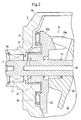
- Fig. 2 relates to the swash plate compressor according to EMBODIMENT 1 and is a cross sectional view showing an essential part thereof.
- Fig. 3 relates to the swash plate compressor according to EMBODIMENT 1 and is a cross sectional view showing, in enlarged scale, an essential part thereof while a drive shaft is rotated at low speed.
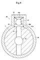
- Fig. 4 relates to the swash plate compressor according to EMBODIMENT 1 and is a cross sectional view showing, in enlarged scale, an essential part thereof while the drive shaft is rotated at high speed.
- Fig. 5 relates to the swash plate compressor according to EMBODIMENT 1 and is a graph illustrating the relationship between the rotating speed of the drive shaft and a throttle area.
- Fig. 6 is a cross sectional view showing a swash plate compressor according to EMBODIMENT 2.
- Fig. 7 is a cross sectional view showing a swash plate compressor of a modified example.
- Fig. 8 is a cross sectional view showing a swash plate compressor of a further modified example.
- a swash plate compressor according to EMBODIMENT 1 is of a variable displacement type used for air-conditioning of a vehicle.
- the compressor includes a housing composed of a cylinder block 1, a front housing 3 and a rear housing 5, and a plurality of cylinder bores 1a extending in parallel to an axis of a drive shaft 7 are provided on the cylinder block 1 to extend therethrough.
- the left in Fig. 1 indicates the front of the compressor and the right indicates the rear of the compressor.
- the front housing 3 and the cylinder block 1 define a crank chamber 15 and axial holes 3a, 1b are formed on the front housing 3 and the cylinder block 1.
- a shaft seal device 17 is provided in the axial hole 3a.
- a rubber material is used for the shaft seal device 17.
- a plain bearing 19 is provided in the axial hole 1b.
- a receiving chamber 1c communicated to the axial hole 1b is formed centrally of a rear end of the cylinder block 1, the receiving chamber 1c is opposed to the valve unit 9.
- the drive shaft 7 is supported to be able to rotate by the shaft seal device 17, etc. in a state, in which one end thereof is exposed from the front housing 3 and a central portion thereof faces into the crank chamber 15.
- a pulley and an electromagnetic clutch both of which are not shown, are connected to the drive shaft 7, and the drive shaft 7 is rotationally driven by a drive source, such as an engine, etc. through a belt stretched round the pulley and the electromagnetic clutch.
- pistons 21, respectively are received in the respective cylinder bores 1a to be able to reciprocate, the respective pistons 21, respectively, defining compression chambers in the cylinder bores 1a.
- a lug plate 23 receiving compressive reaction force is fixed to the drive shaft 7 in the crank chamber 15, and a thrust bearing 25 and a plain bearing 27 are provided between the lug plate 23 and the front housing 3. Also, the drive shaft 7 is inserted through a swash plate 29, of which inclination to an imaginary plane perpendicular to the drive shaft 7 is variable.
- a hinge portion 23a is formed on the lug plate 23 to be directed toward the swash plate 29, a hinge portion 29a is provided on the swash plate 29 to be directed toward the lug plate 23, and the hinge portions 23a, 29a constitute a linkage 31.
- a push spring 33 is provided between the lug plate 23 and the swash plate 29 to bias the both in a direction, in which the both separate from each other.
- pairs of front and rear shoes 35 are provided between the swash plate 29 and the respective pistons 21.
- the shoe 35 on a front side is provided between a front surface of the swash plate 29 and a front seat surface of the piston 21, and the shoe 35 on a rear side is provided between a rear surface of the swash plate 29 and a rear seat surface of the piston 21.
- the respective shoes 35 are substantially semi-spherical in shape. The respective shoes 35 serve as a motion conversion mechanism.
- a first hole 37 extending in a radial direction
- an outflow hole 39 communicated to the first hole 37 to extend coaxially with an axis in an axial direction to extend to a rear end of the drive shaft 7, and a valve hole 41 communicated to the outflow hole 39 to extend in a radial direction.
- the first hole 37 is disposed between the lug plate 23 and the front housing 3 and formed over an extent of a radius of the drive shaft 7 from an axis of the drive shaft 7 to an outer periphery thereof.
- An oil guide groove 3b is formed on the front housing 3 to extend between the front housing 3 and the lug plate 23 from an outer peripheral region of the crank chamber 15 to face the thrust bearing 25.
- an oil guide hole 3c is formed on the front housing 3 to be communicated to the oil guide groove 3b to face the plain bearing 27 and the shaft seal device 17.
- the oil guide hole 3c faces the shaft seal device 17 in the axial hole 3a to be communicated to the first hole 37.
- the oil guide groove 3b and the oil guide hole 3c serve as an oil guide path.
- the rear end of the drive shaft 7 projects into the receiving chamber 1c and a rear end of the outflow hole 39 is closed by a plug member 43.
- the valve hole 41 is formed a little ahead of the plug member 43.
- the valve hole 41 is provided through the drive shaft 7 to communicate the outflow hole 39 to the receiving chamber 1c.
- a valve mechanism 45 is provided round the valve hole 41.
- the valve mechanism 45 includes a spherical-shape valve body 47 that can be seated on one opening 41a of the valve hole 41, and a case 49 fixed to the drive shaft 7 around the valve hole 41.
- the valve body 47 serves also as a mass body.
- the case 49 includes a valve chamber 49a on a side toward the opening 41a.
- a first spring 51 that biases the valve body 47 in a direction away from the opening 41a
- a second spring 53 having a bias that biases the valve body 47 in a direction toward the opening 41a.
- the valve chamber 49a is communicated to the receiving chamber 1c through a communication port 49b formed on the case 49.
- a throttle hole 9a for communication of the receiving chamber 1c with the suction chamber 11 is provided on the valve unit 9 to extend therethrough.
- a second hole 55 is formed on the cylinder block 1 and the valve unit 9 to provide communication between the suction chamber 11 and an inner peripheral region of the crank chamber 15, that is, a region close to the drive shaft 7.
- a throttle 55a is formed on the second hole 55 in the valve unit 9.
- the oil guide groove 3b, the oil guide hole 3c, the first hole 37, the outflow hole 39, the valve hole 41, the communication port 49b, the receiving chamber 1c, and the throttle hole 9a constitute a first passage.
- the second hole 55 constitutes a second passage.
- the communication port 49b and the throttle hole 9a are set to be equal to or larger in opened cross sectional area than the opening 41a of the valve hole 41.
- a capacity control valve 57 is received in the rear housing 5.
- the capacity control valve 57 is communicated to the suction chamber 11 through a detection passage 59 and provides communication between the discharge chamber 13 and the crank chamber 15 through the detection passage 59.
- the capacity control valve 57 detects pressure in the suction chamber 11 to change opening degree of a supply passage 61 to change the discharge capacity of a compressor.
- a pipe 63 is connected to the discharge chamber 13, the pipe 63 being connected to the suction chamber 11 through a check valve 65, a condenser 67, an expansion valve 69, and an evaporator 71.
- the compressor, the check valve 65, the condenser 67, the expansion valve 69, the evaporator 71, and the pipe 63 constitute a refrigerating circuit. Refrigerating gas mixed with lubricating oil is charged in the refrigerating circuit.
- the capacity control valve 57 adjusts pressure in the crank chamber 15 on the basis of pressure in the suction chamber 11 and a flow rate of refrigerating gas to change an angle of the swash plate 29 to the drive shaft 7 to change a discharge capacity thereof.
- valve body 47 of the valve mechanism 45 is caused by large centrifugal force and the bias of the first spring 51 to move away from the axis of the drive shaft 7 against the bias of the second spring 53, whereby the valve body 47 increases opening degree of the opening 41a as shown in Fig. 4 .
- the second hole 55 provides communication in a predetermined cross sectional area between the crank chamber 15 and the suction chamber 11. Therefore, as shown in Fig. 5 , a throttle area, in which the crank chamber 15 and the suction chamber 11 are communicated to each other, becomes large. That is, the single valve mechanism 45 increases a ratio, at which the first hole 37 occupies the release passage, and decreases a ratio, at which the second hole 55 occupies the release passage.
- the lubricating oil is present in abundance and the lubricating oil is led to the first hole 37 through the oil guide groove 3b and the oil guide hole 3c. At this time, the lubricating oil is led to the first hole 37 through the shaft seal device 17, so that a large quantity of the lubricating oil is supplied to the shaft seal device 17 to heighten the shaft seal device 17 in durability.
- refrigerating gas sucked from the suction chamber 11 contains a large quantity of the lubricating oil and sliding portions between the cylinder bores 1a and the pistons 21 are favorably lubricated. Thereby, an excellent durability exhibits itself at high speed.
- valve body 47 of the valve mechanism 45 resists the bias of the first spring 51 because of small centrifugal force and yields to the bias of the second spring 53 to approach the axis of the drive shaft 7 as shown in Fig. 3 , and thus the valve body 47 decreases opening degree of the opening 41a.
- the valve body 47 is seated on the opening 41a to close the valve hole 41.
- the second hole 55 provides communication in a predetermined cross sectional area between the crank chamber 15 and the suction chamber 11. Therefore, as shown in Fig. 5 , a throttle area, in which the crank chamber 15 and the suction chamber 11 are communicated to each other, becomes small. That is, the single valve mechanism 45 decreases a ratio, at which the first hole 37 occupies the release passage, and increases a ratio, at which the second hole 55 occupies the release passage.
- the lubricating oil is small in quantity in an inner peripheral region of the crank chamber 15 shown in Fig. 2 , that is, a region close to the drive shaft 7, and refrigerating gas not containing much of the lubricating oil is led into the second hole 55 from there.
- the first hole 37 is closed when the drive shaft 7 is rotated at low speed. Accordingly, the sum of the cross sectional area of the opening of the release passage decreases whereby refrigerating gas moving to the suction chamber 11 from the crank chamber 15 is decreased in quantity, and refrigerating gas circulated within the swash plate compressor is decreased in quantity whereby refrigerating gas used for the proper object is increased in quantity and the swash plate compressor is improved in performance.
- the swash plate 29 only agitates the lubricating oil at low speed, so that the lubricating oil is little raised in temperature and the lubricating oil is not decreased so much in viscosity. Therefore, sliding portions are still lubricated favorably.
- the compressor can demonstrate an excellent sliding characteristic when the drive shaft 7 is rotated at high speed, and can demonstrate a high refrigerating capacity when the drive shaft 7 is rotated at low speed.
- a plurality of cylinder bores 2a extending in parallel to an axis of a drive shaft 8 are provided on a cylinder block 2 to extend therethrough as shown in Fig. 6 .
- a suction chamber 12 and a discharge chamber 14 are communicated to the respective cylinder bores 2a through a valve unit 10.
- a front housing 4 and the cylinder block 2 define a crank chamber 16 and axial holes 4a, 2b are formed on the front housing 4 and the cylinder block 2.
- a shaft seal device 18 and a plain bearing 20 are provided in the axial hole 4a.
- a rubber material is used for the shaft seal device 18.
- a plain bearing 22 is provided in the axial hole 2b.
- a receiving chamber 2c communicated to the axial hole 2b is formed centrally of a rear end of the cylinder block 2, the receiving chamber 2c being opposed to the valve unit 10.
- the drive shaft 8 is supported by the shaft seal device 18, etc. in a state to be able to rotate, in which one end thereof is exposed from the front housing 4 and a central portion thereof faces the crank chamber 16. Also, pistons 24, respectively, are received in the respective cylinder bores 2a to be able to reciprocate, the respective pistons 24 defining compression chambers in the cylinder bores 2a.
- a lug plate 26 receiving compressive reaction force is fixed to the drive shaft 8 in the crank chamber 16, and a thrust bearing 28 is provided between the lug plate 26 and the front housing 4. Also, the drive shaft 8 is inserted through a swash plate 30 to make the same variable in inclination angle.
- a linkage 32 is formed between the lug plate 26 and the swash plate 30.
- push springs 34, 36 are provided between the lug plate 26 and the swash plate 30 and between the swash plate 30 and the drive shaft 8. Also, pairs of front and rear shoes 38 are provided between the swash plate 30 and the respective pistons 24.
- the drive shaft 8 comprises a body 8a, of which a rear end is formed to be cylindrical-shaped, and a tubular body 8b in the form of a cylinder inserted from the rear end of the body 8a to be fixed in the body 8a.
- a first hole 40 being annular and extending in an axial direction is defined between the body 8a and the tubular body 8b.
- a guide hole 26a formed midway thereof with a step is formed on the lug plate 26 to be perpendicular to an axis. The guide hole 26a is communicated at an inner end thereof to the first hole 40 and communicated at an outer end thereof to an outer peripheral region of the crank chamber 16.
- a valve chamber 26b is defined midway the guide hole 26a in the lug plate 26 and a valve mechanism 42 is provided in the valve chamber 26b.
- the valve mechanism 42 comprises a valve body 42a that can be seated on an opening of the guide hole 26a on an inner end side, and a spring 42b that biases the valve body 42a in a direction of seating.
- the valve body 42a serves as a mass body.
- a cylindrical-shaped cover body 26c is press fitted into the guide hole 26a outside the valve chamber 26b to support one end of the spring 42b.
- a second hole 44 Formed on the body 8a of the drive shaft 8 are a second hole 44 extending radially, and a communication hole 46 communicated to the second hole 44 to extend coaxially with an axis in an axial direction.
- an outflow hole 48 communicated to the communication hole 46 to extend to a rear end of the drive shaft 8.
- the second hole 44 is disposed between the shaft seal device 18 and the plain bearing 20 to be formed over an extent of a radius of the drive shaft 8 from an axis of the drive shaft 8 to an outer periphery thereof.
- An oil guide hole 4b is formed on the front housing 4 to open to an inner peripheral region of the crank chamber 16 between the front housing 4 and the lug plate 26. The oil guide hole 4b faces the shaft seal device 18 in the axial hole 4a to be communicated to the second hole 44.
- the rear end of the drive shaft 8 projects into the receiving chamber 2c.
- a throttle hole 10a for communication of the receiving chamber 2c with the suction chamber 12 is provided on the valve unit 10 to extend therethrough.
- the guide hole 26a, the valve chamber 26b, the first hole 40, the oil guide hole 4b, the second hole 44, the communication hole 46, the outflow hole 48, the receiving chamber 2c, and the throttle hole 10a constitute a release passage.
- the guide hole 26a, the valve chamber 26b, the first hole 40, the receiving chamber 2c, and the throttle hole 10a constitute a first passage.
- the oil guide hole 4b, the second hole 44, the communication hole 46, the outflow hole 48, the receiving chamber 2c, and the throttle hole 10a constitute a second passage.
- the remaining construction is the same as that of EMBODIMENT 1.
- the valve body 42a of the valve mechanism 42 is caused by large centrifugal force to get away from the axis of the drive shaft 8 against the bias of the spring 42b, whereby the valve body 42a increases opening degree of the guide hole 26a.
- the second hole 44 provides communication in a predetermined cross sectional area between the crank chamber 16 and the suction chamber 12. Therefore, a throttle area, in which the crank chamber 16 and the suction chamber 12 are communicated to each other, becomes large. Therefore, the single valve mechanism 42 is increased a ratio, at which the first hole 40 occupies the release passage, and decreased a ratio, at which the second hole 44 occupies the release passage.
- the valve body 42a of the valve mechanism 42 is caused by the bias of the spring 42b to approach the axis of the drive shaft 8 against small centrifugal force, and thus the valve body 42a decreases opening degree of the guide hole 26a.
- the valve body 42a is seated on the guide hole 26a.
- the second hole 44 provides communication in a predetermined cross sectional area between the crank chamber 16 and the suction chamber 12. Therefore, a throttle area, in which the crank chamber 16 and the suction chamber 12 are communicated to each other, becomes small. Therefore, the single valve mechanism 42 is decreased a ratio, at which the first hole 40 occupies the release passage, and increased a ratio, at which the second hole 44 occupies the release passage.
- the compressor With the compressor, since the oil guide hole 4b is communicated to an inner peripheral region of the crank chamber 16 and only a small quantity of the lubricating oil is supplied to the oil guide hole 4b when the compressor is rotated at high speed, the compressor of EMBODIMENT 1 is excellent in terms of durability of the rubber material for the shaft seal device 18 when the compressor is rotated at high speed. However, the lubricating oil can be supplied to the shaft seal device 18 at all times.
- the throttle hole 9b is set to be equal to or larger in opened cross sectional area than the sun of the opened cross sectional areas of the opening 41a of the valve hole 41 and the throttle 55b.
- an opening of the guide hole 26a on an outer end side thereof be forward in a direction of rotation of the lug plate 26 to facilitate taking the lubricating oil in the crank chamber 16 into the guide hole 26a.
- a release passage may be provided between the respective rollers and ratios, at which the first passage and the second passage occupy the release passage, may be changed.
- the linkages 31, 32 are not limited to those in the embodiments but various arrangements may be adopted.
- the invention can be made use of in air-conditioning apparatuses for vehicles.
- a swash plate compressor capable of realizing demonstration of an excellent sliding characteristic when a drive shaft is rotated at high speed, and demonstration of a high refrigerating capacity when the drive shaft is rotated at low speed.
- an oil guide groove 3b, an oil guide hole 3c, a first hole 37, an outflow hole 39, a valve hole 41, a communication port 49b, a receiving chamber 1c, a throttle hole 9a, and a second hole 55 constitute a release passage.
- the oil guide groove 3b, the oil guide hole 3c, the first hole 37, the outflow hole 39, the valve hole 41, the communication port 49b, the receiving chamber 1c, and the throttle hole 9a constitute a first passage.
- the second hole 55 constitute a second passage.
- a valve mechanism 45 increases a ratio, at which the first passage occupies the release passage, as a drive shaft 7 is increased in rotating speed.
Landscapes
- Engineering & Computer Science (AREA)
- Mechanical Engineering (AREA)
- General Engineering & Computer Science (AREA)
- Compressors, Vaccum Pumps And Other Relevant Systems (AREA)
Abstract
Description
- The present invention relates to a swash plate compressor.
-
JP-A-8-284816 - Also, the swash plate compressor is formed with a release passage, which communicates the crank chamber to the suction chamber. With the swash plate compressor disclosed in the aforementioned patent application publication, the release passage includes a first radial hole formed to extend radially of the drive shaft, and an outflow hole which communicates the first radial hole to the suction chamber. A lug plate is fixed to the drive shaft in a manner to rotate together therewith and an oil supply passage is formed on the lug plate to extend toward a center from an outer peripheral region of the crank chamber. Also, a shaft seal device is provided to seal between the front housing and the drive shaft, and a lubrication passage is formed on the front housing to communicate the oil supply passage to the first radial hole at a location where the shaft seal device is provided.
- The swash plate compressor together with a condenser, an expansion valve, and an evaporator constitutes a refrigerating circuit, and the refrigerating circuit is used air-conditioning apparatus for a vehicle. With the swash plate compressor, the capacity control valve adjusts pressure in the crank chamber on the basis of pressure in the suction chamber or a flow rate of refrigerating gas to change an angle of the swash plate with respect to the drive shaft to thereby change a discharge capacity thereof.
- Also, with the swash plate compressor, in an outer peripheral region of the crank chamber, lubricating oil is present in abundance in the crank chamber, and the release passage composed of the oil supply passage, the lubrication passage, the first radial hole and the outflow hole is communicated to that region, in which the lubricating oil is present in abundance, so that it is possible to supply the lubricating oil in the crank chamber to the shaft seal device, thus enabling improving durability of a rubber material for the shaft seal device.
- With a swash plate compressor, when a drive shaft is rotated at high speed, an improvement in sliding characteristic is demanded between cylinder bores and pistons, and between a swash plate and respective shoes, and so on. Also, when a drive shaft is rotated at low speed, lubricating oil in refrigerating gas discharged to an external refrigerating circuit outside a swash plate compressor is demanded of reduction in quantity to demonstrate a high refrigerating capacity.
- In this respect, with the swash plate compressor disclosed in the aforementioned patent application publication, the release passage communicates an oil rich region, in which lubricating oil is present in abundance in the crank chamber, in a predetermined cross sectional area with the suction chamber at all times, so that the lubricating oil in the crank chamber is made excessively small or large in quantity irrespective of the rotating speed of the drive shaft. When the lubricating oil in the crank chamber is excessively large in quantity while the drive shaft is increased in rotating speed, the swash plate agitates the lubricating oil excessively, so that the lubricating oil is liable to generate heat due to shearing and to decrease in viscosity. In this case, there is a fear in lubrication of sliding portions. Also, when the lubricating oil in the crank chamber is excessively small in quantity while the drive shaft is decreased in rotating speed, the lubricating oil in refrigerating gas discharged to a refrigerating circuit outside the swash plate compressor is increased in quantity and so the refrigerating capacity becomes insufficient.
- An object of the invention is to provide a swash plate compressor capable of realizing an excellent sliding characteristic when a drive shaft is rotated at high speed, and a high refrigerating capacity when the drive shaft is rotated at low speed.
- Refrigerating gas mixed with lubricating oil is adopted in a swash plate compressor. According to experiments conducted by the inventors of the present invention, there are present an oil rich region, in which the lubricating oil is large in quantity, and an oil poor region, in which the lubricating oil is small in quantity, in a crank chamber of a swash plate compressor. For example, the oil rich region is present in an outer peripheral region of the crank chamber, and the oil poor region is present in an inner peripheral region of the crank chamber, that is, a region away from a wall surface of the crank chamber. This is because a swash plate rotates together with a drive shaft in the crank chamber and the lubricating oil is forced out into the outer peripheral region of the crank chamber by centrifugal force. Also, the lubricating oil is present in abundance on a peripheral surface of a cylinder bore. The invention has been accomplished based on these ascertainments.
- The invention provides a swash plate compressor comprising: a housing including a cylinder bore, a suction chamber, a discharge chamber and a crank chamber, a drive shaft rotatably supported by the housing, a swash plate supported on the drive shaft in the crank chamber, a piston reciprocatingly accommodated in the cylinder bore, a motion conversion mechanism provided between the swash plate and the piston to convert a wobbling motion of the swash plate into reciprocation of the piston, and a release passage for communication of the crank chamber to the suction chamber, the compressor being characterized in that the release passage includes a first passage communicated to an oil rich region, in which lubricating oil is large in quantity in the crank chamber, a valve mechanism is provided to increase opening degree of the first passage as the drive shaft is increased in rotating speed, and the valve mechanism is provided on the first passage to be displaced by centrifugal force.
- With the swash plate compressor of the invention, when the drive shaft is rotated at high speed, the valve mechanism increases opening degree of the first passage. Therefore, refrigerating gas containing a large quantity of the lubricating oil in the crank chamber is moved to the suction chamber by the first passage, opening degree of which is increased. Therefore, the lubricating oil in the crank chamber becomes moderate in quantity and so the swash plate does not agitate the lubricating oil so much, so that the lubricating oil is hard to generate heat due to shearing and hard to decrease in viscosity. Therefore, sliding portions are favorably lubricated. Also, refrigerating gas sucked from the suction chamber contains a large quantity of the lubricating oil and sliding portions between the cylinder bore and the piston are favorably lubricated. In addition, while the lubricating oil contained in refrigerating gas discharged to a refrigerating circuit outside the swash plate compressor are increased in quantity at this time, no problem is caused in refrigerating capacity since the piston reciprocates at high speed.
- In addition, with the swash plate compressor, while the lubricating oil in the crank chamber is increased in quantity when the drive shaft is rotated at low speed, the swash plate or the like only agitates the lubricating oil at low speed, so that the lubricating oil is not decreased so much in viscosity and the lubricating oil is little raised in temperature. Therefore, sliding portions are still lubricated favorably.
- The valve mechanism is provided on the first passage to be displaced by the centrifugal force. A mechanical valve mechanism is adopted, in which a mass body is displaced by the centrifugal force and a valve body is actuated. Therefore, an increase in the centrifugal force causes a displacement in a direction, in which the first passage is increased in opening degree, and a decrease in the centrifugal force causes a displacement in a direction, in which the first passage is decreased in opening degree.
- Accordingly, with the swash plate compressor of the invention, it is possible to realize an excellent sliding characteristic when a drive shaft is rotated at high speed, and a high refrigerating capacity when the drive shaft is rotated at low speed.
- The swash plate compressor of the invention may be of a fixed displacement type, in which a swash plate is invariable in inclination angle, or may be of a variable displacement type, in which a swash plate is variable in inclination angle.
- Also, with the swash plate compressor of the invention, the release passage may be enough to communicate the crank chamber to the suction chamber, may be one for direct communication of the crank chamber to the suction chamber, or may be one for indirect communication of the crank chamber to the suction chamber through a suction passage, etc. communicated to the suction chamber. The release passage suffices to include the first passage, or may include another passage.
- The first passage is communicated to any one of those regions, in which lubricating oil is present in abundance. Regions, in which the lubricating oil is present in abundance, are determined by intercomparison with other regions.
- The release passage can include a second passage communicated to that region, in which lubricating oil is small in quantity in the crank chamber. The valve mechanism can increase a ratio, at which the first passage occupies the release passage, as the drive shaft is increased in rotating speed, and can decrease a ratio, at which the second passage occupies the release passage, as the drive shaft is decreased in rotating speed.
- In this case, the release passage comprises the first passage and the second passage and refrigerating gas not containing much of the lubricating oil in the crank chamber can be moved to the suction chamber by the second passage. Therefore, the valve mechanism is liable to change a ratio, at which the first passage occupies the release passage, so that an improvement in responsibility relative to the rotating speed is achieved.
- Also, with the swash plate compressor, when the drive shaft is rotated at low speed, the valve mechanism decreases a ratio, at which the first passage occupies the release passage. Therefore, refrigerating gas containing a large quantity of lubricating oil in the crank chamber is not moved so much to the suction chamber by the first passage decreased in that ratio, at which it occupies the release passage, but refrigerating gas not containing much of the lubricating oil in the crank chamber is moved to the suction chamber by the second passage. Therefore, the lubricating oil contained in refrigerating gas discharged to a refrigerating circuit outside the swash plate compressor are decreased in quantity, so that a high refrigerating capacity is demonstrated.
- Further, with the swash plate compressor, when the drive shaft is rotated at low speed, the sum of the cross sectional area of the opening of the release passage decreases whereby refrigerating gas moving to the suction chamber from the crank chamber is decreased in outflow and refrigerating gas circulated within the compressor is decreased in quantity, so that refrigerating gas used for the proper object is increased in quantity and the compressor is improved in performance. In particular, with a clutchless type swash plate compressor, in which power is transmitted to a drive shaft of the swash plate compressor at all times in operation of a drive source, refrigerating gas is only circulated within the compressor when cooling is not needed, but refrigerating gas as circulated can be made minimum when the drive shaft is rotated at low speed, so that it is possible to realize demonstration of an excellent sliding characteristic when the drive shaft is rotated at high speed, and reduction in power for the compressor when the drive shaft is rotated at low speed.
- The second passage is preferably formed with a throttle.
- In this case, refrigerating gas not containing much of the lubricating oil in the crank chamber is made difficult to move to the suction chamber, so that the effect of the invention produced by the lubricating oil becomes conspicuous.
- With the swash plate compressor of the invention, the swash plate can be supported to be variable in inclination angle. Also, a lug plate receiving compressive reaction force can be fixed to the drive shaft to be able to rotate integrally. Further, an oil guide path can be formed on the housing to extend between the housing and the lug plate from an outer peripheral region of the crank chamber. The first passage is preferably communicated to the oil guide path.
- According to experiments conducted by the inventors of the present invention, an outer peripheral region of a crank chamber in a swash plate compressor is a region, in which lubricating oil is present in abundance, so that it is possible to readily lead the lubricating oil to a first passage via the oil guide path.
- A shaft seal device can be provided between the housing and the drive shaft to seal the drive shaft exposed from the housing. The first passage is preferably communicated to the oil guide path via the shaft seal device.
- In this case, by supplying a large quantity of lubricating oil to the shaft seal device, it is possible to improve durability of a rubber material for the shaft seal device.
- With the swash plate compressor of the invention, the swash plate can be supported to be variable in inclination angle. Also, a lug plate receiving compressive reaction force can be fixed to the drive shaft to be able to rotate integrally. Further, the first passage can include a guide hole formed on the lug plate and opened to an outer peripheral region of the crank chamber.
- According to results of tests made by inventors of the present application, an outer peripheral region of a crank chamber in a swash plate compressor is a region, in which lubricating oil is present in abundance, so that it is possible to readily lead the lubricating oil to a first passage via the oil guide hole.
- With the swash plate compressor of the invention, a shaft seal device can be provided between the housing and the drive shaft to seal the drive shaft exposed from the housing. Also, the second passage is preferably opened to the crank chamber in the vicinity of the shaft seal device.
- In this case, lubricating oil can be supplied to the shaft seal device at all times, so that the shaft seal device can be improved in durability.
-
Fig. 1 is a cross sectional view showing a swash plate compressor according toEMBODIMENT 1. -
Fig. 2 relates to the swash plate compressor according toEMBODIMENT 1 and is a cross sectional view showing an essential part thereof. -
Fig. 3 relates to the swash plate compressor according toEMBODIMENT 1 and is a cross sectional view showing, in enlarged scale, an essential part thereof while a drive shaft is rotated at low speed. -
Fig. 4 relates to the swash plate compressor according toEMBODIMENT 1 and is a cross sectional view showing, in enlarged scale, an essential part thereof while the drive shaft is rotated at high speed. -
Fig. 5 relates to the swash plate compressor according toEMBODIMENT 1 and is a graph illustrating the relationship between the rotating speed of the drive shaft and a throttle area. -
Fig. 6 is a cross sectional view showing a swash plate compressor according toEMBODIMENT 2. -
Fig. 7 is a cross sectional view showing a swash plate compressor of a modified example. -
Fig. 8 is a cross sectional view showing a swash plate compressor of a further modified example. - Embodiments 1 and 2, in which the invention is embodied, will be described below with reference to the drawings.
- A swash plate compressor according to
EMBODIMENT 1 is of a variable displacement type used for air-conditioning of a vehicle. As shown inFig. 1 , the compressor includes a housing composed of acylinder block 1, afront housing 3 and arear housing 5, and a plurality of cylinder bores 1a extending in parallel to an axis of adrive shaft 7 are provided on thecylinder block 1 to extend therethrough. In addition, the left inFig. 1 indicates the front of the compressor and the right indicates the rear of the compressor. - Formed on the
rear housing 5 are asuction chamber 11 and adischarge chamber 13, which are communicated to the respective cylinder bores 1a through avalve unit 9. Also, thefront housing 3 and thecylinder block 1 define a crankchamber 15 andaxial holes front housing 3 and thecylinder block 1. Ashaft seal device 17 is provided in theaxial hole 3a. A rubber material is used for theshaft seal device 17. Also, aplain bearing 19 is provided in theaxial hole 1b. A receivingchamber 1c communicated to theaxial hole 1b is formed centrally of a rear end of thecylinder block 1, the receivingchamber 1c is opposed to thevalve unit 9. - The
drive shaft 7 is supported to be able to rotate by theshaft seal device 17, etc. in a state, in which one end thereof is exposed from thefront housing 3 and a central portion thereof faces into thecrank chamber 15. A pulley and an electromagnetic clutch, both of which are not shown, are connected to thedrive shaft 7, and thedrive shaft 7 is rotationally driven by a drive source, such as an engine, etc. through a belt stretched round the pulley and the electromagnetic clutch. Also,pistons 21, respectively, are received in the respective cylinder bores 1a to be able to reciprocate, therespective pistons 21, respectively, defining compression chambers in the cylinder bores 1a. - A
lug plate 23 receiving compressive reaction force is fixed to thedrive shaft 7 in thecrank chamber 15, and athrust bearing 25 and aplain bearing 27 are provided between thelug plate 23 and thefront housing 3. Also, thedrive shaft 7 is inserted through aswash plate 29, of which inclination to an imaginary plane perpendicular to thedrive shaft 7 is variable. Ahinge portion 23a is formed on thelug plate 23 to be directed toward theswash plate 29, ahinge portion 29a is provided on theswash plate 29 to be directed toward thelug plate 23, and thehinge portions linkage 31. Also, a push spring 33 is provided between thelug plate 23 and theswash plate 29 to bias the both in a direction, in which the both separate from each other. - Also, pairs of front and
rear shoes 35 are provided between theswash plate 29 and therespective pistons 21. Theshoe 35 on a front side is provided between a front surface of theswash plate 29 and a front seat surface of thepiston 21, and theshoe 35 on a rear side is provided between a rear surface of theswash plate 29 and a rear seat surface of thepiston 21. Therespective shoes 35 are substantially semi-spherical in shape. Therespective shoes 35 serve as a motion conversion mechanism. - Formed on the
drive shaft 7 are afirst hole 37 extending in a radial direction, anoutflow hole 39 communicated to thefirst hole 37 to extend coaxially with an axis in an axial direction to extend to a rear end of thedrive shaft 7, and avalve hole 41 communicated to theoutflow hole 39 to extend in a radial direction. - As shown in
Fig. 2 , thefirst hole 37 is disposed between thelug plate 23 and thefront housing 3 and formed over an extent of a radius of thedrive shaft 7 from an axis of thedrive shaft 7 to an outer periphery thereof. Anoil guide groove 3b is formed on thefront housing 3 to extend between thefront housing 3 and thelug plate 23 from an outer peripheral region of thecrank chamber 15 to face thethrust bearing 25. Also, anoil guide hole 3c is formed on thefront housing 3 to be communicated to theoil guide groove 3b to face theplain bearing 27 and theshaft seal device 17. Theoil guide hole 3c faces theshaft seal device 17 in theaxial hole 3a to be communicated to thefirst hole 37. Theoil guide groove 3b and theoil guide hole 3c serve as an oil guide path. - As shown in
Fig. 1 , the rear end of thedrive shaft 7 projects into the receivingchamber 1c and a rear end of theoutflow hole 39 is closed by aplug member 43. Thevalve hole 41 is formed a little ahead of theplug member 43. As shown inFigs. 3 and4 , thevalve hole 41 is provided through thedrive shaft 7 to communicate theoutflow hole 39 to the receivingchamber 1c. - A
valve mechanism 45 is provided round thevalve hole 41. Thevalve mechanism 45 includes a spherical-shape valve body 47 that can be seated on oneopening 41a of thevalve hole 41, and acase 49 fixed to thedrive shaft 7 around thevalve hole 41. Thevalve body 47 serves also as a mass body. Thecase 49 includes avalve chamber 49a on a side toward theopening 41a. Provided in thevalve chamber 49a are afirst spring 51 that biases thevalve body 47 in a direction away from theopening 41a, and asecond spring 53 having a bias that biases thevalve body 47 in a direction toward theopening 41a. Thevalve chamber 49a is communicated to the receivingchamber 1c through acommunication port 49b formed on thecase 49. - As shown in
Fig. 1 , athrottle hole 9a for communication of the receivingchamber 1c with thesuction chamber 11 is provided on thevalve unit 9 to extend therethrough. Also, asecond hole 55 is formed on thecylinder block 1 and thevalve unit 9 to provide communication between thesuction chamber 11 and an inner peripheral region of thecrank chamber 15, that is, a region close to thedrive shaft 7. Athrottle 55a is formed on thesecond hole 55 in thevalve unit 9. Theoil guide groove 3b, theoil guide hole 3c, thefirst hole 37, theoutflow hole 39, thevalve hole 41, thecommunication port 49b, the receivingchamber 1c, thethrottle hole 9a, and thesecond hole 55 constitute a release passage. Theoil guide groove 3b, theoil guide hole 3c, thefirst hole 37, theoutflow hole 39, thevalve hole 41, thecommunication port 49b, the receivingchamber 1c, and thethrottle hole 9a constitute a first passage. Also, thesecond hole 55 constitutes a second passage. In addition, thecommunication port 49b and thethrottle hole 9a are set to be equal to or larger in opened cross sectional area than theopening 41a of thevalve hole 41. - Also, a
capacity control valve 57 is received in therear housing 5. Thecapacity control valve 57 is communicated to thesuction chamber 11 through adetection passage 59 and provides communication between thedischarge chamber 13 and thecrank chamber 15 through thedetection passage 59. Thecapacity control valve 57 detects pressure in thesuction chamber 11 to change opening degree of asupply passage 61 to change the discharge capacity of a compressor. - A
pipe 63 is connected to thedischarge chamber 13, thepipe 63 being connected to thesuction chamber 11 through acheck valve 65, acondenser 67, anexpansion valve 69, and anevaporator 71. The compressor, thecheck valve 65, thecondenser 67, theexpansion valve 69, theevaporator 71, and thepipe 63 constitute a refrigerating circuit. Refrigerating gas mixed with lubricating oil is charged in the refrigerating circuit. - With the compressor thus constructed, the
capacity control valve 57 adjusts pressure in thecrank chamber 15 on the basis of pressure in thesuction chamber 11 and a flow rate of refrigerating gas to change an angle of theswash plate 29 to thedrive shaft 7 to change a discharge capacity thereof. - Also, with the compressor, when the
drive shaft 7 is rotated at high speed while a vehicle is running at high speed, thevalve body 47 of thevalve mechanism 45 is caused by large centrifugal force and the bias of thefirst spring 51 to move away from the axis of thedrive shaft 7 against the bias of thesecond spring 53, whereby thevalve body 47 increases opening degree of theopening 41a as shown inFig. 4 . - Therefore, opening degree, at which the
valve hole 41 is communicated to thecommunication port 49b, increases and opening degree, at which thefirst hole 37 shown inFig. 2 is communicated to thecommunication port 49b, increases. At this time, thesecond hole 55 provides communication in a predetermined cross sectional area between thecrank chamber 15 and thesuction chamber 11. Therefore, as shown inFig. 5 , a throttle area, in which thecrank chamber 15 and thesuction chamber 11 are communicated to each other, becomes large. That is, thesingle valve mechanism 45 increases a ratio, at which thefirst hole 37 occupies the release passage, and decreases a ratio, at which thesecond hole 55 occupies the release passage. - In an outer peripheral region of the
crank chamber 15 shown inFig. 2 , the lubricating oil is present in abundance and the lubricating oil is led to thefirst hole 37 through theoil guide groove 3b and theoil guide hole 3c. At this time, the lubricating oil is led to thefirst hole 37 through theshaft seal device 17, so that a large quantity of the lubricating oil is supplied to theshaft seal device 17 to heighten theshaft seal device 17 in durability. - Owing to the
first hole 37 increased in that ratio, at which it occupies the release passage, refrigerating gas disposed in thecrank chamber 15 and containing a large quantity of the lubricating oil is led to the receivingchamber 1c through theoutflow hole 39, thevalve hole 41, and thecommunication port 49b and further moved to thesuction chamber 11 via thethrottle hole 9a. Therefore, the lubricating oil in thecrank chamber 15 becomes moderate in quantity and so theswash plate 29 does not agitate the lubricating oil so much, so that the lubricating oil is hard to generate heat due to shearing and hard to decrease in viscosity. Therefore, sliding portions between theswash plate 29 and therespective shoes 35 are favorably lubricated. Also, refrigerating gas sucked from thesuction chamber 11 contains a large quantity of the lubricating oil and sliding portions between the cylinder bores 1a and thepistons 21 are favorably lubricated. Thereby, an excellent durability exhibits itself at high speed. - In addition, while the lubricating oil contained in refrigerating gas discharged to the refrigerating circuit outside the compressor are increased in quantity at this time, no problem is caused in refrigerating capacity since the
pistons 21 reciprocate at high speed. - Also, when the
drive shaft 7 is rotated at low speed while a vehicle is running at low speed, thevalve body 47 of thevalve mechanism 45 resists the bias of thefirst spring 51 because of small centrifugal force and yields to the bias of thesecond spring 53 to approach the axis of thedrive shaft 7 as shown inFig. 3 , and thus thevalve body 47 decreases opening degree of theopening 41a. When thedrive shaft 7 is rotated at a further low speed, thevalve body 47 is seated on theopening 41a to close thevalve hole 41. - Therefore, opening degree, at which the
valve hole 41 is communicated to thecommunication port 49b, decreases and opening degree, at which thefirst hole 37 shown inFig. 2 is communicated to thecommunication port 49b, decreases. Also, at this time, thesecond hole 55 provides communication in a predetermined cross sectional area between thecrank chamber 15 and thesuction chamber 11. Therefore, as shown inFig. 5 , a throttle area, in which thecrank chamber 15 and thesuction chamber 11 are communicated to each other, becomes small. That is, thesingle valve mechanism 45 decreases a ratio, at which thefirst hole 37 occupies the release passage, and increases a ratio, at which thesecond hole 55 occupies the release passage. - The lubricating oil is small in quantity in an inner peripheral region of the
crank chamber 15 shown inFig. 2 , that is, a region close to thedrive shaft 7, and refrigerating gas not containing much of the lubricating oil is led into thesecond hole 55 from there. - Owing to the
second hole 55 increased in that ratio, at which it occupies the release passage, refrigerating gas not containing much of the lubricating oil within thecrank chamber 15 is moved to thesuction chamber 11 via thethrottle 55a. Therefore, the lubricating oil contained in refrigerating gas discharged to the refrigerating circuit outside the compressor is decreased in quantity, so that a high refrigerating capacity exhibits itself. - Further, with the swash plate compressor, the
first hole 37 is closed when thedrive shaft 7 is rotated at low speed. Accordingly, the sum of the cross sectional area of the opening of the release passage decreases whereby refrigerating gas moving to thesuction chamber 11 from thecrank chamber 15 is decreased in quantity, and refrigerating gas circulated within the swash plate compressor is decreased in quantity whereby refrigerating gas used for the proper object is increased in quantity and the swash plate compressor is improved in performance. - In addition, while the lubricating oil in the
crank chamber 15 is increased in quantity, theswash plate 29 only agitates the lubricating oil at low speed, so that the lubricating oil is little raised in temperature and the lubricating oil is not decreased so much in viscosity. Therefore, sliding portions are still lubricated favorably. - Accordingly, the compressor can demonstrate an excellent sliding characteristic when the
drive shaft 7 is rotated at high speed, and can demonstrate a high refrigerating capacity when thedrive shaft 7 is rotated at low speed. - With a swash plate compressor according to
EMBODIMENT 2, a plurality of cylinder bores 2a extending in parallel to an axis of adrive shaft 8 are provided on acylinder block 2 to extend therethrough as shown inFig. 6 . Formed on arear housing 6 are asuction chamber 12 and adischarge chamber 14, which are communicated to the respective cylinder bores 2a through avalve unit 10. Also, a front housing 4 and thecylinder block 2 define a crankchamber 16 andaxial holes cylinder block 2. Ashaft seal device 18 and aplain bearing 20 are provided in theaxial hole 4a. A rubber material is used for theshaft seal device 18. Also, a plain bearing 22 is provided in theaxial hole 2b. A receivingchamber 2c communicated to theaxial hole 2b is formed centrally of a rear end of thecylinder block 2, the receivingchamber 2c being opposed to thevalve unit 10. - The
drive shaft 8 is supported by theshaft seal device 18, etc. in a state to be able to rotate, in which one end thereof is exposed from the front housing 4 and a central portion thereof faces thecrank chamber 16. Also,pistons 24, respectively, are received in the respective cylinder bores 2a to be able to reciprocate, therespective pistons 24 defining compression chambers in the cylinder bores 2a. - A
lug plate 26 receiving compressive reaction force is fixed to thedrive shaft 8 in thecrank chamber 16, and athrust bearing 28 is provided between thelug plate 26 and the front housing 4. Also, thedrive shaft 8 is inserted through aswash plate 30 to make the same variable in inclination angle. Alinkage 32 is formed between thelug plate 26 and theswash plate 30. Also, push springs 34, 36 are provided between thelug plate 26 and theswash plate 30 and between theswash plate 30 and thedrive shaft 8. Also, pairs of front andrear shoes 38 are provided between theswash plate 30 and therespective pistons 24. - The
drive shaft 8 comprises abody 8a, of which a rear end is formed to be cylindrical-shaped, and atubular body 8b in the form of a cylinder inserted from the rear end of thebody 8a to be fixed in thebody 8a. Afirst hole 40 being annular and extending in an axial direction is defined between thebody 8a and thetubular body 8b. Aguide hole 26a formed midway thereof with a step is formed on thelug plate 26 to be perpendicular to an axis. Theguide hole 26a is communicated at an inner end thereof to thefirst hole 40 and communicated at an outer end thereof to an outer peripheral region of thecrank chamber 16. Avalve chamber 26b is defined midway theguide hole 26a in thelug plate 26 and avalve mechanism 42 is provided in thevalve chamber 26b. Thevalve mechanism 42 comprises avalve body 42a that can be seated on an opening of theguide hole 26a on an inner end side, and aspring 42b that biases thevalve body 42a in a direction of seating. Thevalve body 42a serves as a mass body. A cylindrical-shapedcover body 26c is press fitted into theguide hole 26a outside thevalve chamber 26b to support one end of thespring 42b. - Formed on the
body 8a of thedrive shaft 8 are asecond hole 44 extending radially, and acommunication hole 46 communicated to thesecond hole 44 to extend coaxially with an axis in an axial direction. Formed on thetubular body 8b is anoutflow hole 48 communicated to thecommunication hole 46 to extend to a rear end of thedrive shaft 8. Thesecond hole 44 is disposed between theshaft seal device 18 and theplain bearing 20 to be formed over an extent of a radius of thedrive shaft 8 from an axis of thedrive shaft 8 to an outer periphery thereof. Anoil guide hole 4b is formed on the front housing 4 to open to an inner peripheral region of thecrank chamber 16 between the front housing 4 and thelug plate 26. Theoil guide hole 4b faces theshaft seal device 18 in theaxial hole 4a to be communicated to thesecond hole 44. The rear end of thedrive shaft 8 projects into the receivingchamber 2c. - A
throttle hole 10a for communication of the receivingchamber 2c with thesuction chamber 12 is provided on thevalve unit 10 to extend therethrough. Theguide hole 26a, thevalve chamber 26b, thefirst hole 40, theoil guide hole 4b, thesecond hole 44, thecommunication hole 46, theoutflow hole 48, the receivingchamber 2c, and thethrottle hole 10a constitute a release passage. Theguide hole 26a, thevalve chamber 26b, thefirst hole 40, the receivingchamber 2c, and thethrottle hole 10a constitute a first passage. Also, theoil guide hole 4b, thesecond hole 44, thecommunication hole 46, theoutflow hole 48, the receivingchamber 2c, and thethrottle hole 10a constitute a second passage. The remaining construction is the same as that ofEMBODIMENT 1. - With the compressor, when the
drive shaft 8 is rotated at high speed while a vehicle is running at high speed, or the like, thevalve body 42a of thevalve mechanism 42 is caused by large centrifugal force to get away from the axis of thedrive shaft 8 against the bias of thespring 42b, whereby thevalve body 42a increases opening degree of theguide hole 26a. At this time, thesecond hole 44 provides communication in a predetermined cross sectional area between thecrank chamber 16 and thesuction chamber 12. Therefore, a throttle area, in which thecrank chamber 16 and thesuction chamber 12 are communicated to each other, becomes large. Therefore, thesingle valve mechanism 42 is increased a ratio, at which thefirst hole 40 occupies the release passage, and decreased a ratio, at which thesecond hole 44 occupies the release passage. - Also, when the
drive shaft 8 is rotated at low speed while a vehicle is running at low speed, or the like, thevalve body 42a of thevalve mechanism 42 is caused by the bias of thespring 42b to approach the axis of thedrive shaft 8 against small centrifugal force, and thus thevalve body 42a decreases opening degree of theguide hole 26a. When thedrive shaft 8 is rotated at a further low speed, thevalve body 42a is seated on theguide hole 26a. At this time, thesecond hole 44 provides communication in a predetermined cross sectional area between thecrank chamber 16 and thesuction chamber 12. Therefore, a throttle area, in which thecrank chamber 16 and thesuction chamber 12 are communicated to each other, becomes small. Therefore, thesingle valve mechanism 42 is decreased a ratio, at which thefirst hole 40 occupies the release passage, and increased a ratio, at which thesecond hole 44 occupies the release passage. - Accordingly, with the compressor, the same function and effect as those of
EMBODIMENT 1 can be produced. With the compressor, since theoil guide hole 4b is communicated to an inner peripheral region of thecrank chamber 16 and only a small quantity of the lubricating oil is supplied to theoil guide hole 4b when the compressor is rotated at high speed, the compressor ofEMBODIMENT 1 is excellent in terms of durability of the rubber material for theshaft seal device 18 when the compressor is rotated at high speed. However, the lubricating oil can be supplied to theshaft seal device 18 at all times. - While the invention has been described with respect to
EMBODIMENT 1 andEMBODIMENT 2, it goes without saying that the invention is not limited toEMBODIMENT 1 andEMBODIMENT 2 but can be appropriately changed within a scope not departing from the gist thereof and applied. - For example, as shown in
Fig. 7 , it is possible in the compressor ofEMBODIMENT 1 to remove thethrottle 55 as a second passage and to form on the drive shaft 7 a throttle 55b, which provides communication between theoutflow hole 39 and the receivingchamber 1c and is the same in diameter as thethrottle 55a, as a second passage. - With such construction, a second passage is easy to form; the lubricating oil can be supplied to the
shaft seal device 18 at all times, and the same effect as that ofEMBODIMENT 2 can be produced. In addition, in this case, the throttle hole 9b is set to be equal to or larger in opened cross sectional area than the sun of the opened cross sectional areas of theopening 41a of thevalve hole 41 and the throttle 55b. - Also, as shown in
Fig. 8 , it is possible to remove thethrottle 55 as a second passage and to provide agroove 55c, which bypasses thevalve body 47, as a second passage on theopening 41a of thevalve hole 41. With such construction, the same effect can be produced. - Also, with the compressor of
EMBODIMENT 2, it is preferred that an opening of theguide hole 26a on an outer end side thereof be forward in a direction of rotation of thelug plate 26 to facilitate taking the lubricating oil in thecrank chamber 16 into theguide hole 26a. - Also, in the case where radial bearings using rollers are adopted in place of the
plain bearings 19, 22 in the compressors ofEMBODIMENT 1 andEMBODIMENT 2, a release passage may be provided between the respective rollers and ratios, at which the first passage and the second passage occupy the release passage, may be changed. Also, thelinkages - The invention can be made use of in air-conditioning apparatuses for vehicles.
There is provided a swash plate compressor capable of realizing demonstration of an excellent sliding characteristic when a drive shaft is rotated at high speed, and demonstration of a high refrigerating capacity when the drive shaft is rotated at low speed.
With the swash plate compressor of the invention, anoil guide groove 3b, anoil guide hole 3c, afirst hole 37, anoutflow hole 39, avalve hole 41, acommunication port 49b, a receivingchamber 1c, athrottle hole 9a, and asecond hole 55 constitute a release passage. Theoil guide groove 3b, theoil guide hole 3c, thefirst hole 37, theoutflow hole 39, thevalve hole 41, thecommunication port 49b, the receivingchamber 1c, and thethrottle hole 9a constitute a first passage. Also, thesecond hole 55 constitute a second passage. Avalve mechanism 45 increases a ratio, at which the first passage occupies the release passage, as adrive shaft 7 is increased in rotating speed.
Claims (7)
- A swash plate compressor comprising:a housing including a cylinder bore, a suction chamber, a discharge chamber and a crank chamber,a drive shaft rotatably supported by the housing,a swash plate supported on the drive shaft in the crank chamber,a piston reciprocatingly accommodated in the cylinder bore,a motion conversion mechanism provided between the swash plate and the piston to convert wobbling motion of the swash plate into reciprocation of the piston, anda release passage for communication of the crank chamber to the suction chamber,the compressor being characterized in that the release passage includes a first passage communicated to an oil rich region, in which lubricating oil is large in quantity in the crank chamber,a valve mechanism is provided to increase opening degree of the first passage as the drive shaft is increased in rotating speed, andthe valve mechanism is provided on the first passage to be displaced by centrifugal force.
- The swash plate compressor according to claim 1, wherein the release passage includes a second passage communicated to an oil poor region, in which the lubricating oil is small in quantity in the crank chamber, and
the valve mechanism increases a ratio, at which the first passage occupies the release passage, as the drive shaft is increased in rotating speed, and decreases a ratio, at which the second passage occupies the release passage, as the drive shaft is decreased in rotating speed. - The swash plate compressor according to claim 2, wherein the second passage is formed with a throttle.
- The swash plate compressor according to claim 2, wherein the swash plate is supported to be variable in inclination angle,
a lug plate receiving compressive reaction force is fixed to the drive shaft and rotates integrally with the drive shaft,
an oil guide path is formed on the housing to extend between the housing and the lug plate from an outer peripheral region of the crank chamber, and
the first passage is communicated to the oil guide path. - The swash plate compressor according to claim 4, wherein a shaft seal device is provided to seal between the housing and the drive shaft, and
the first passage is communicated to the oil guide path at a position close to the shaft seal device. - The swash plate compressor according to claim 2, wherein the swash plate is supported to be variable in inclination angle,
a lug plate receiving compressive reaction force is fixed to the drive shaft and rotates integrally with the drive shaft, and
the first passage includes a guide hole formed on the lug plate and opened to an outer peripheral region of the crank chamber. - The swash plate compressor according to claim 6, wherein a shaft seal device is provided to seal between the housing and the drive shaft, and
the second passage is opened to the crank chamber in the vicinity of the shaft seal device.
Applications Claiming Priority (3)
| Application Number | Priority Date | Filing Date | Title |
|---|---|---|---|
| JP2008025757 | 2008-02-05 | ||
| JP2008038686A JP4924464B2 (en) | 2008-02-05 | 2008-02-20 | Swash plate compressor |
| JP2008052548A JP2009209739A (en) | 2008-03-03 | 2008-03-03 | Swash plate compressor |
Publications (1)
| Publication Number | Publication Date |
|---|---|
| EP2088318A1 true EP2088318A1 (en) | 2009-08-12 |
Family
ID=40652870
Family Applications (1)
| Application Number | Title | Priority Date | Filing Date |
|---|---|---|---|
| EP09151428A Withdrawn EP2088318A1 (en) | 2008-02-05 | 2009-01-27 | Swash plate compressor |
Country Status (2)
| Country | Link |
|---|---|
| US (1) | US20090220355A1 (en) |
| EP (1) | EP2088318A1 (en) |
Cited By (3)
| Publication number | Priority date | Publication date | Assignee | Title |
|---|---|---|---|---|
| US9163620B2 (en) | 2011-02-04 | 2015-10-20 | Halla Visteon Climate Control Corporation | Oil management system for a compressor |
| US20170122300A1 (en) * | 2014-06-27 | 2017-05-04 | Valeo Japan Co., Ltd. | Variable displacement swash plate compressor |
| CN108361178A (en) * | 2018-03-26 | 2018-08-03 | 合肥达因汽车空调有限公司 | A kind of oil-gas separated-type noise reduction swash-plate-type compressor |
Families Citing this family (2)
| Publication number | Priority date | Publication date | Assignee | Title |
|---|---|---|---|---|
| JP4924464B2 (en) * | 2008-02-05 | 2012-04-25 | 株式会社豊田自動織機 | Swash plate compressor |
| JP5065120B2 (en) * | 2008-03-28 | 2012-10-31 | サンデン株式会社 | Reciprocating compressor |
Citations (6)
| Publication number | Priority date | Publication date | Assignee | Title |
|---|---|---|---|---|
| US4685866A (en) * | 1985-03-20 | 1987-08-11 | Kabushiki Kaisha Toyoda Jidoshokki Seisakusho | Variable displacement wobble plate type compressor with wobble angle control unit |
| JPH08284816A (en) | 1995-04-10 | 1996-10-29 | Toyota Autom Loom Works Ltd | Swash plate type compressor |
| US5836748A (en) * | 1994-07-13 | 1998-11-17 | Kabushiki Kaisha Toyoda Jidoshokki Seisakusho | Swash plate type variable displacement compressor utilizing a spool for controlling the inclination |
| EP1207301A2 (en) * | 2000-11-17 | 2002-05-22 | Kabushiki Kaisha Toyota Jidoshokki | Variable displacement compressor |
| EP1614896A1 (en) * | 2004-07-09 | 2006-01-11 | Kabushiki Kaisha Toyota Jidoshokki | Variable displacement compressor |
| EP1717445A1 (en) * | 2005-04-27 | 2006-11-02 | Kabushiki Kaisha Toyota Jidoshokki | Compressor |
Family Cites Families (22)
| Publication number | Priority date | Publication date | Assignee | Title |
|---|---|---|---|---|
| US4688997A (en) * | 1985-03-20 | 1987-08-25 | Kabushiki Kaisha Toyoda Jidoshokki Seisakusho | Variable displacement compressor with variable angle wobble plate and wobble angle control unit |
| US4872814A (en) * | 1988-06-09 | 1989-10-10 | General Motors Corporation | Variable displacement compressor passive destroker |
| WO1991017360A1 (en) * | 1990-04-27 | 1991-11-14 | Sanyo Electric Co., Ltd. | Scroll compressor |
| JPH08109880A (en) * | 1994-10-11 | 1996-04-30 | Toyota Autom Loom Works Ltd | Operation control system for variable displacement type compressor |
| JPH1162824A (en) * | 1997-08-08 | 1999-03-05 | Sanden Corp | Variable capacity compressor |
| JP3820766B2 (en) * | 1998-03-06 | 2006-09-13 | 株式会社豊田自動織機 | Compressor |
| JP2000283027A (en) * | 1999-03-26 | 2000-10-10 | Toyota Autom Loom Works Ltd | Variable displacement type compressor |
| JP2000283028A (en) * | 1999-03-26 | 2000-10-10 | Toyota Autom Loom Works Ltd | Variable displacement type compressor |
| JP2001343024A (en) * | 2000-03-29 | 2001-12-14 | Toyota Industries Corp | Power transmission mechanism |
| JP2002225549A (en) * | 2001-02-05 | 2002-08-14 | Toyota Industries Corp | Vehicle air conditioner |
| JP2002364669A (en) * | 2001-06-04 | 2002-12-18 | Toyota Industries Corp | Power transmission mechanism |
| JP2002364668A (en) * | 2001-06-04 | 2002-12-18 | Toyota Industries Corp | Power transmission mechanism |
| JP2004324591A (en) * | 2003-04-25 | 2004-11-18 | Toyota Industries Corp | Hybrid compressor |
| JP2005002927A (en) * | 2003-06-12 | 2005-01-06 | Toyota Industries Corp | Piston type compressor |
| JP4483699B2 (en) * | 2005-01-27 | 2010-06-16 | 株式会社豊田自動織機 | Swash plate compressor |
| EP2076674B1 (en) * | 2006-06-30 | 2012-10-03 | Doowon Technical College | Oil separating structure of variable displacement compressor |
| JP2008075460A (en) * | 2006-09-19 | 2008-04-03 | Toyota Industries Corp | Compressor |
| JP2008144631A (en) * | 2006-12-07 | 2008-06-26 | Toyota Industries Corp | Variable displacement compressor |
| KR100887231B1 (en) * | 2007-11-22 | 2009-03-06 | 학교법인 두원학원 | Capacity variable compressor with drive shaft refrigerant flow |
| JP4924464B2 (en) * | 2008-02-05 | 2012-04-25 | 株式会社豊田自動織機 | Swash plate compressor |
| JP2009203888A (en) * | 2008-02-28 | 2009-09-10 | Toyota Industries Corp | Variable displacement type swash plate compressor |
| JP2009209910A (en) * | 2008-03-06 | 2009-09-17 | Toyota Industries Corp | Swash plate compressor |
-
2009
- 2009-01-27 EP EP09151428A patent/EP2088318A1/en not_active Withdrawn
- 2009-01-30 US US12/362,713 patent/US20090220355A1/en not_active Abandoned
Patent Citations (6)
| Publication number | Priority date | Publication date | Assignee | Title |
|---|---|---|---|---|
| US4685866A (en) * | 1985-03-20 | 1987-08-11 | Kabushiki Kaisha Toyoda Jidoshokki Seisakusho | Variable displacement wobble plate type compressor with wobble angle control unit |
| US5836748A (en) * | 1994-07-13 | 1998-11-17 | Kabushiki Kaisha Toyoda Jidoshokki Seisakusho | Swash plate type variable displacement compressor utilizing a spool for controlling the inclination |
| JPH08284816A (en) | 1995-04-10 | 1996-10-29 | Toyota Autom Loom Works Ltd | Swash plate type compressor |
| EP1207301A2 (en) * | 2000-11-17 | 2002-05-22 | Kabushiki Kaisha Toyota Jidoshokki | Variable displacement compressor |
| EP1614896A1 (en) * | 2004-07-09 | 2006-01-11 | Kabushiki Kaisha Toyota Jidoshokki | Variable displacement compressor |
| EP1717445A1 (en) * | 2005-04-27 | 2006-11-02 | Kabushiki Kaisha Toyota Jidoshokki | Compressor |
Cited By (4)
| Publication number | Priority date | Publication date | Assignee | Title |
|---|---|---|---|---|
| US9163620B2 (en) | 2011-02-04 | 2015-10-20 | Halla Visteon Climate Control Corporation | Oil management system for a compressor |
| US20170122300A1 (en) * | 2014-06-27 | 2017-05-04 | Valeo Japan Co., Ltd. | Variable displacement swash plate compressor |
| US10309382B2 (en) * | 2014-06-27 | 2019-06-04 | Valeo Japan Co., Ltd. | Variable displacement swash plate compressor |
| CN108361178A (en) * | 2018-03-26 | 2018-08-03 | 合肥达因汽车空调有限公司 | A kind of oil-gas separated-type noise reduction swash-plate-type compressor |
Also Published As
| Publication number | Publication date |
|---|---|
| US20090220355A1 (en) | 2009-09-03 |
Similar Documents
| Publication | Publication Date | Title |
|---|---|---|
| US8360742B2 (en) | Swash plate compressor | |
| US20090223244A1 (en) | Swash plate type compressor | |
| EP2096308B1 (en) | Swash plate type variable displacement compressor | |
| JP2014092108A (en) | Variable displacement swash plate type compressor | |
| US20090220355A1 (en) | Swash plate compressor | |
| JP2009102989A (en) | Variable displacement compressor | |
| KR20120090312A (en) | Variable displacement swash plate type compressor | |
| JP2018076782A (en) | Variable displacement swash plate compressor | |
| JP2017150438A (en) | Piston type swash plate compressor | |
| JP4648845B2 (en) | Swash plate type and swing swash plate type variable capacity compressor | |
| CN101503993B (en) | Swash plate compressor | |
| US10815980B2 (en) | Variable displacement swash plate type compressor | |
| JP2012202394A (en) | Swash plate type variable displacement compressor | |
| JP2017145827A (en) | Variable displacement swash plate compressor | |
| JP2009209739A (en) | Swash plate compressor | |
| JP6179438B2 (en) | Variable capacity swash plate compressor | |
| JP2002005010A (en) | Variable displacement compressor | |
| JP2019183837A (en) | Piston compressor | |
| JP4529868B2 (en) | One side swash plate type variable capacity compressor | |
| JP2009174430A (en) | Swash plate compressor | |
| WO2005111417A1 (en) | Compressor | |
| JP2017150315A (en) | Variable displacement swash plate compressor | |
| JP4562661B2 (en) | Swash plate compressor | |
| JP2019112980A (en) | Variable displacement swash plate compressor | |
| JP2019183836A (en) | Piston compressor |
Legal Events
| Date | Code | Title | Description |
|---|---|---|---|
| PUAI | Public reference made under article 153(3) epc to a published international application that has entered the european phase |
Free format text: ORIGINAL CODE: 0009012 |
|
| 17P | Request for examination filed |
Effective date: 20090127 |
|
| AK | Designated contracting states |
Kind code of ref document: A1 Designated state(s): AT BE BG CH CY CZ DE DK EE ES FI FR GB GR HR HU IE IS IT LI LT LU LV MC MK MT NL NO PL PT RO SE SI SK TR |
|
| AX | Request for extension of the european patent |
Extension state: AL BA RS |
|
| 17Q | First examination report despatched |
Effective date: 20100308 |
|
| AKX | Designation fees paid |
Designated state(s): DE FR IT |
|
| STAA | Information on the status of an ep patent application or granted ep patent |
Free format text: STATUS: THE APPLICATION IS DEEMED TO BE WITHDRAWN |
|
| 18D | Application deemed to be withdrawn |
Effective date: 20100720 |